EP2570735A1 - Système de cheminée de ventilation et procédé de fonctionnement dýun tel système - Google Patents
Système de cheminée de ventilation et procédé de fonctionnement dýun tel système Download PDFInfo
- Publication number
- EP2570735A1 EP2570735A1 EP12183183A EP12183183A EP2570735A1 EP 2570735 A1 EP2570735 A1 EP 2570735A1 EP 12183183 A EP12183183 A EP 12183183A EP 12183183 A EP12183183 A EP 12183183A EP 2570735 A1 EP2570735 A1 EP 2570735A1
- Authority
- EP
- European Patent Office
- Prior art keywords
- air
- treatment device
- branch
- hood
- extractor
- Prior art date
- Legal status (The legal status is an assumption and is not a legal conclusion. Google has not performed a legal analysis and makes no representation as to the accuracy of the status listed.)
- Granted
Links
Images


Classifications
-
- F—MECHANICAL ENGINEERING; LIGHTING; HEATING; WEAPONS; BLASTING
- F24—HEATING; RANGES; VENTILATING
- F24C—DOMESTIC STOVES OR RANGES ; DETAILS OF DOMESTIC STOVES OR RANGES, OF GENERAL APPLICATION
- F24C15/00—Details
- F24C15/20—Removing cooking fumes
Definitions
- the invention relates to a fume extraction system and a method for operating a fume extraction system.
- the use of cooker hoods is known.
- the contaminated air which is also referred to as fumes or vapors, usually cleaned on the one hand via a grease filter and the other via odor filter.
- odor filter for example, activated carbon filter cassettes or activated carbon filter mats are known, which are arranged in the housing of the extractor hood in the flow direction of the air before or after the blower of the extractor hood.
- a disadvantage of this known type of air purification is that the impurities, in particular the odors in an activated carbon filter are only taken and stored in this and therefore can escape from the activated carbon filter again. Moreover, it is disadvantageous in these known extractor hoods that the entire air emerging from the fan of the extractor hood is passed over the odor filter and its service life is therefore reduced and / or the air quality exiting the odor filter is impaired.
- Object of the present invention is therefore to provide a solution by means of which a targeted and efficient cleaning of air, in particular removal of odors from the air can be achieved.
- the invention is based on the finding that this object can be achieved by the air leaving the extractor hood can be subjected to different treatments.
- a fume extraction system which has an extractor hood and at least one air treatment device.
- the extractor hood system is characterized in that the air treatment device is connected to the extractor hood via an air duct and has at least one plasma source for the air treatment, the extractor system between the extractor hood and the at least one air treatment device has a branch of the air duct and at least one air guiding device is provided in the region of the branch, which is adjustable in at least three operating positions.
- the extractor hood which is also referred to below as a hood or hood, preferably represents a kitchen extractor hood.
- the extractor hood has a blower, are sucked through the air, in particular steam and vapor from the area below and / or around the extractor hood in this.
- the fan is also called a fan.
- at least one grease filter is preferably provided for removing grease or other contaminants, such as water droplets.
- At least one air outlet is provided on the extractor hood, which can be configured as a pipe or pipe socket on the fan housing of the extractor hood.
- An air treatment device is a device in which air is at least partially actively treated and cleaned.
- the air treatment device is therefore also referred to as a cleaning unit or air cleaner.
- the air treatment device has at least one plasma source according to the invention.
- odors contained in the air may be at least partially decomposed.
- the air treatment device may also have at least one filter in addition to the plasma source. This filter is used in the air treatment device according to the invention predominantly the inclusion of not or not completely decomposed odors.
- reactive species such as ozone, which may be present in the treatment of the air by the plasma, may also be included in the filter.
- the filter therefore preferably surrounds at least partially the space in which the plasma is generated and the air is treated with the plasma.
- the filter which is also referred to as an odor filter, may, for example, have activated carbon or other adsorbent as filter material.
- the air treatment device is connected to the extractor hood.
- the air treatment device When connected to the extractor hood, according to the invention, it is preferable to connect or arrange the air treatment device in FIG or understood on the housing of the hood, for example in the chimney of the hood.
- an air duct is provided between the extractor hood and the air treatment device.
- This air duct may be provided for example as a pipe, hose or channel.
- the air guide connects to the blower housing, in particular an outlet of the blower housing, the hood.
- the branch which is provided according to the invention in the air duct, can be configured as a branch, bifurcation or other division of the air duct.
- At least one air guiding device is provided.
- air guiding device in particular a device for air deflection or air blocking is referred to.
- the spoiler can also be referred to as an air switch.
- the air guiding device when arranged in the region of the branch, it is preferable to understand an arrangement directly at the branch or in the flow direction after the branch in the vicinity of the branch.
- the air supply to the air treatment device or the at least one further branch, which is also referred to below as the branch, of the branch can be set.
- the spoiler device can be adjusted in at least three operating positions.
- positions or settings of the air guiding device are understood to mean operating positions in which these can be held and thus direct the air flow in different directions over at least a certain time. Due to the different operating positions of the spoiler different operating conditions of the extractor system are thus set.
- the spoiler device may have locking elements or other fixing element, such as stops, which can hold the spoiler in the at least three operating positions.
- the three operating positions of the spoiler device which can preferably be adjusted, are designated in particular as a cleaning position, discharge position and mixing position. If the air-guiding device is set to the cleaning position, preferably the entire air flow emerging from the extractor hood is conducted to the air-conditioning device and cleaned there, that is to say especially freed of odors. From the air treatment device, the cleaned air flow back into the room in which the hood is operated, be returned. In the cleaning position of the air guiding device, the operating state set on the extractor system is referred to as a cleaning state or a cleaning operation.
- the entire air flow emerging from the extractor hood is preferably conducted past the air treatment device, that is to say it does not reach the air treatment device.
- a discharge operation is set to the extractor system.
- This can be a recirculation mode or an exhaust air mode.
- a circulating air operation the air is passed after passing the spoiler to an air line, which leads, for example via a home ventilation system in another room or directly back into the room in which the hood of the extractor system is operated.
- an exhaust air operation the air is passed after passing the air guide to an air line, which may for example represent an exhaust pipe or exhaust air system and into the environment, that leads to the outside.
- a mixing state or mixing operation of the extractor system which is a mixture of cleaning operation and discharge operation, that is, recirculation or exhaust air operation, is set.
- a part of the air flow exiting the extractor hood is preferably conducted to the air treatment device and another part is routed past the air treatment device to at least one air line and from there either into the room or into the environment.
- the advantage of the extractor system according to the invention is that the air that has been sucked in from the extractor hood and optionally already freed from contaminants, such as fat and / or liquid particles, can be cleaned in a targeted and efficient manner and, in particular, odors are removed from the air can.
- the efficiency is achieved in the extractor hood system according to the invention in particular by the fact that the air supply to an air treatment device or other components can be adjusted specifically and adapted to the ambient conditions.
- the use of an air treatment device with a plasma source also destroys or decomposing the odors, which is advantageous over the pure separation of the odors in known filters, since leakage of the odors from the air treatment device can be largely prevented.
- the plasma source of the air treatment device comprises means for generating a dielectric barrier discharge, in particular at least two electrodes.
- This type of plasma generation is also referred to as DBE.
- DBE is in particular the electrical discharge between two electrodes, which are separated by an insulating dielectric barrier.
- air can be present between the electrodes and, in particular, the air to be treated can flow between the electrodes. This simplifies the construction of the air treatment device and, moreover, good mixing of the air to be treated in the air treatment device can be achieved.
- the DBE generates a plasma, by means of which the air entering the air treatment device is subjected to high energy and is thus treated. In particular, odors contained in the air are decomposed.
- the air deflector of the extractor system is adjustable in at least three operating positions, even with the discharge of a portion of the air flow in a branch of the air duct, which is not connected to the air treatment device, a certain air supply to the air treatment device can continue to be ensured.
- This condition is also called mixed state.
- the air treatment device is a separate device to the hood, which is connected via the air duct with the extractor hood.
- the connection can be made via channels or pipes as described above.
- the separate embodiment of the air treatment device has a number of advantages.
- the air treatment device can also be provided subsequently for operation with the extractor hood.
- the Dimensions of the air treatment device are selected according to the functions of the air treatment device and do not necessarily have to be adapted to the dimensions of the extractor hood.
- the air treatment device is preferably provided in a housing of the extractor device, for example, received in a chimney or duct of the extractor hood.
- the branch of the air duct has at least three branches, wherein one of the branches is connected to the extractor hood, one of the branches to the air treatment device and one of the branches to an air line.
- the branch, which is connected to the air line, according to the invention can also represent the air line itself.
- An air duct is hereby referred to a system by means of which air can be discharged into the environment and / or into the room in which the extractor hood is operated or into another room.
- the air line can therefore lead to the outside, that is, the air is discharged outside the building.
- the air line can also be a house ventilation system.
- the air line can also lead into the room in which the hood is operated.
- the air is led away from the hood.
- the air depending on the ambient conditions or the conditions of the components of the extractor system can be passed into the corresponding branches of the air duct.
- the amount of air that is directed to the air conditioning device can be minimized.
- the air treatment device is less stressed and its service life can thus be increased.
- the further branch of the air duct is connected to an air line, which is followed by an exhaust air system or exhaust air duct, for example, air with a high degree of contamination can be led out of the building instead of passing it via the air treatment device.
- the temperatures in the room in which the hood is operated, and the environment can be considered.
- the air can always be returned to the room where the cooker hood is operated.
- This recirculation may be via the air treatment device or via an air line, which is referred to as recirculation line, done. This energy can be saved because the heated room air is returned to the room.
- the extractor system can be used to ventilate the room by releasing the air into the environment.
- At least one filter element is arranged in the air line which is connected to or represents one of the branches of the branch.
- This filter element preferably represents an odor filter, which may be, for example, an activated carbon filter.
- the filter element is particularly preferably provided in the cases in which the air line leads back to the room in which the extractor hood is operated.
- the filter element is therefore preferably provided in a recirculation line or a house ventilation system. In this case, the filter element in the vicinity of the branch or even at a different location, in particular just before the exit of the air duct in the room in which the hood is operated, or be arranged in another room.
- the spoiler device is a flap.
- This embodiment is particularly simple in construction and handling.
- the flap may in this case be provided at the junction so that it covers at least a part of the cross section of one of the branches, which depart from the branch, depending on the set position or position.
- the setting can be made even more accurate.
- other air guiding devices are also possible which at least temporarily reduce the cross section of at least one of the branch branches.
- the air guiding device is infinitely adjustable in different positions or positions.
- more than three operating positions of the spoiler device can be adjusted.
- the cleaning state and the derivative state are still included in the possible states.
- a number of mixed states can be set. This is advantageous because it allows a further increase in efficiency.
- the drive of the spoiler device and its fixation in the different states can be done particularly advantageous in this embodiment by a motor.
- the air guiding device is connected to at least one sensor, in particular a sensor for determining the air condition.
- a sensor for determining the air condition for example, the temperature in the room in which the extractor hood is operated, the outside temperature, the difference between these two temperatures, the air humidity and / or the loading of the inside air with impurities (for example VOC (volatile organic compounds)) are referred to as the air condition.
- impurities for example VOC (volatile organic compounds)
- the determined values can then serve as parameters for the automatic adjustment of the operating position of the air guiding device.
- the extractor system has a control unit for controlling the at least one air guiding device.
- the spoiler device can be brought into the different operating positions and optionally also held there.
- the control unit can serve to determine the operating position of the air guiding device to be set.
- the control unit may be connected to sensors, for example. By means of these sensors, the air state can then be determined and from this the suitable operating state of the extractor system to be set via the air guiding device can be determined.
- the control of the spoiler device (s) is preferably carried out automatically, for example via one or more motors.
- the invention relates to a method for operating a fume extraction system according to the invention.
- the method is characterized in that at least one of at least three operating states of the extractor system is set by the air guiding device.
- the air guiding device is controlled as a function of at least one state variable of the air condition.
- FIG. 1 a first embodiment of a fume extraction system 1 according to the present invention is shown.
- the extractor hood system 1 comprises an extractor hood 10 and an air treatment device 11 connected thereto.
- the extractor hood 10 is connected to the air treatment device 11 via an air guide 12.
- the extractor hood 10 is located above a hob 2, in the illustrated embodiment between upper cabinets 3 a kitchenette.
- the air treatment device 11 is arranged in the illustrated embodiment on one of the upper cabinets 3 between the upper cabinet 3 and the ceiling 4, the room in which the hood 10 is operated. This room is referred to below as a kitchen.
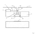
- FIG. 5 One possible construction of the air treatment device 11 is schematic in FIG. 5 shown.
- This air treatment device 11 has in particular a housing 110, as well as a plasma source 111 arranged therein.
- the plasma source 111 comprises two electrodes 111 a, 111 b arranged parallel to one another. Via these electrodes 111 a, 111 b, a DBE is initiated.
- FIG. 5 For better visibility of the interior of the housing 110, the top and the front of the housing 110 are not shown.
- This top and front of the housing 110 may for example consist of a filter, the in turn, as a filter material, for example, may have activated carbon. It is also within the scope of the invention, at least partially, to form further or other sides of the housing 110 through a filter.
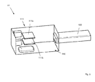
- a branch 120 is provided in the air guide 12, a branch 120 is provided.
- the air duct 12 is at this junction of the branch 121, which emanates from the hood 10, in two branches or branches 122, 123 on.
- the branch 122 leads to the air treatment device 11 and the branch 123 passes through the ceiling 4.
- the branch 123 instead of through the ceiling 4 can also pass through the kitchen wall to which the hood 10 is attached, or through another kitchen wall. Outside the room, this branch 123, for example, in an unillustrated exhaust system or a home ventilation system, also not shown.
- the branch 123 thus constitutes an air duct branch in the sense of the present invention.
- sensors 14, 15 are attached to the hood 10 and outside the room, in particular the kitchen.
- the sensor 14 is used, for example, to detect the air condition in the kitchen, while the sensor 15, which is located outside the room, for example, serves to detect the outside temperature.
- the position of the sensors 14, 15 is in the FIG. 1 only indicated schematically. It is also within the scope of the invention, the sensor 14 at a different location in the kitchen, for example, at a different location on the hood 10 or spaced to the hood 10 to order.
- the sensor 15 may be provided, for example, on the outside of the building.
- an air guiding device 13 is arranged in the form of a flap.
- the spoiler 13 is provided at the branch 120.
- branch 122 By pivoting the spoiler 13 can optionally branch 122, which leads to the air treatment device 11 or the branch 123, which leads through the ceiling 4, are closed.
- FIG. 1 shown position of the spoiler 13 is derived from the hood 10 air flow flowing through the branch 121 of the air duct 120, between the branch 122 and the branch 123 divided. The spoiler 13 is thus in a mixing position.
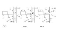
- the different operating conditions or flow conditions of the extractor system at different operating positions of the air guiding device 13 are schematically in the FIGS. 4a to 4c shown.
- the air guiding device 13 is set so that it completely closes the branch 122 to the air treatment device 11 of the extractor system 1.
- the entire air coming from the extractor hood 10 flows via the branch 121 to the branch 120 and is introduced there into the branch 123.
- the air enters an exhaust system or a home ventilation system (both not shown).
- This operating position of the spoiler device which in FIG. 4a is also referred to as Ab effetswolf state and the operating state of the extractor system generated thereby is referred to as Ab effetsschreib.
- the operating state of the extractor system is also referred to as exhaust air operation.
- a home ventilation system is connected, then the operating state of the extractor system is also referred to as recirculation mode or circulation mode.
- FIG. 4b is already in FIG. 1 shown mixed state in which the air flow from the branch 121 of the hood 10 into air streams in the branches 122 and 123 divides.
- the air flow purified in the air treatment device 11 may at least partially exit via the air treatment device 11. This is in FIG. 4b indicated by the block arrows on the air treatment device 11.
- the air preferably exits from this after passing through a filter in the air treatment device 11.
- the filter (not shown) therefore preferably forms part of the wall of the air treatment device 11.
- FIG 4c the air guiding device 13 is shown in a cleaning position.
- the thus set operating state of the extractor system is also referred to as a cleaning state.
- the air guiding device 13 completely closes the branch 123 of the air guide 120, so that the entire air flow guided by the extractor hood 10 into the branch 121 is conducted into the air treatment device 11 where it is treated or treated. From the air treatment device 11, the air can then be returned to the kitchen.
- control unit 16 In the FIGS. 4a to c is also a control unit 16 indicated.
- the control unit 16 may be connected to the sensors 14, 15 and use the received sensor signals to determine a suitable operating position of the air guiding device 13.
- FIG. 2 a second embodiment of the extractor system 1 according to the invention is shown.
- the second embodiment differs from the first embodiment only by the air guide 120.
- the branch 121 which originates from the extractor hood 10, in the already described branch 122 to the air treatment device 11 and a second branch 124 over.
- the branch 124 represents an air duct, which leads to the kitchen and ends there.
- a filter element 125 is provided at the end of the air duct 124. This filter element 125 preferably represents an odor filter.
- only one sensor 14 is provided, via which the air condition in the kitchen can be detected.
- an air guiding device 13 is provided, via which the air flow from the branch 121 is selectively directed into the branch 122 or the branch 124 or partially into each of these two branches 122, 124.
- the entire guided by the cooker hood 10 in the branch 120 air is returned to the kitchen.
- the return takes place either via the air treatment device 11 or via the filter element 125 or both via the air treatment device 11 and via the filter element 125th
- FIG. 3 a third embodiment of the extractor system 1 is shown.
- This embodiment differs from the second embodiment FIG. 2 in that, in addition to the branches 122 and 124, a branch 123 according to the first embodiment of FIG. 1 is provided, which leads out of the room in which the hood 10 is operated.
- an air guiding device 13 is likewise provided at the branch 120. Via the air guiding device 13, the air coming from the branch 121 from the extractor hood 10 can be routed either to the air treatment device 11, to the filter element 125 or into an exhaust air or house ventilation system (not shown) connected to the branch 123.
- mixing states can be set via the air guiding device 13, in which, for example, only part of the air flow from the branch 121 to the air treatment device 11 and another part to the filter element 125 and / or to the exhaust air or home ventilation system (not shown) is directed.
- the invention is not limited to the embodiments shown.
- an air treatment device which is also referred to as an air cleaner unit and, for example, based on dielectric barrier discharge (DBE) works with a cooker hood, which is also referred to as extractor hood combined.
- a spoiler such as a flap
- the air flow either completely in an exhaust system, which is also referred to as exhaust system, a home ventilation system or a filter or similar or without filter back into the room air is passed.
- the air can be passed according to the invention after passing through the air cleaner back into the room air.
- the position of the spoiler, such as the flap is free or adjustable in stages, but can also automatically depending on parameters such as the outdoor and indoor temperature, the relative humidity, the VOC (volatile organic compond) load on indoor air, controlled become.
- An advantage of this invention is that, for example, in winter, the heated room air is not blown into the open and thus reduces the heat loss on the other hand, if necessary, the ventilation can take place outdoors in summer. Another advantage is that air conditioned in the summer does not have to be released outside.
- the extractor system for example, depending on the filter aging or piping, by the controller, in particular by the control by the air deflector, also be optimized in terms of pressure drop and noise.
- an activated carbon filter is used as an odor filter on the hood, existing odors in the air cleaner, for example, reduced from cooking processes instead of being stored and thus can not, as in conventional activated carbon filters escape again.
Applications Claiming Priority (1)
| Application Number | Priority Date | Filing Date | Title |
|---|---|---|---|
| DE102011082928A DE102011082928A1 (de) | 2011-09-19 | 2011-09-19 | Dunstabzugssystem und Verfahren zum Betreiben eines Dunstabzugssystems |
Publications (2)
| Publication Number | Publication Date |
|---|---|
| EP2570735A1 true EP2570735A1 (fr) | 2013-03-20 |
| EP2570735B1 EP2570735B1 (fr) | 2019-06-26 |
Family
ID=46758685
Family Applications (1)
| Application Number | Title | Priority Date | Filing Date |
|---|---|---|---|
| EP12183183.8A Active EP2570735B1 (fr) | 2011-09-19 | 2012-09-05 | Système de cheminée de ventilation et procédé de fonctionnement d'un tel système |
Country Status (3)
| Country | Link |
|---|---|
| EP (1) | EP2570735B1 (fr) |
| DE (1) | DE102011082928A1 (fr) |
| DK (1) | DK2570735T3 (fr) |
Cited By (5)
| Publication number | Priority date | Publication date | Assignee | Title |
|---|---|---|---|---|
| EP2789921A1 (fr) * | 2013-04-09 | 2014-10-15 | Silverline Küchengeräte und Handel GmbH | Hotte aspirante |
| WO2017140554A1 (fr) * | 2016-02-15 | 2017-08-24 | Bruckbauer, Wilhelm | Dispositif pour agencer une ou plusieurs électrodes d'un filtre à plasma dans le boîtier d'une hotte aspirante |
| CN108087939A (zh) * | 2018-01-23 | 2018-05-29 | 武汉浩航环保科技有限公司 | 一种盘式烟尘颗粒物分离机 |
| CN108826407A (zh) * | 2018-07-20 | 2018-11-16 | 广东美的厨房电器制造有限公司 | 吊顶式烟机 |
| EP3667176A1 (fr) * | 2018-12-11 | 2020-06-17 | Franke Futurum AB | Hotte d'extraction de fumée, procédé de fonctionnement d'une hotte d'extraction de fumée |
Families Citing this family (4)
| Publication number | Priority date | Publication date | Assignee | Title |
|---|---|---|---|---|
| EP2937633A1 (fr) | 2014-04-22 | 2015-10-28 | E.G.O. ELEKTRO-GERÄTEBAU GmbH | Dispositif de purification d'air, dispositif d'aération et procédé de purification d'air |
| DE102019121115A1 (de) * | 2019-08-05 | 2021-02-11 | Miele & Cie. Kg | Luftbehandlungssystem zur Verbesserung einer Luftqualität einer Innenluft in einem Raum und Verfahren zu dessen Betrieb |
| CN113251455B (zh) * | 2021-07-07 | 2022-03-04 | 南京德力通环境科技有限公司 | 一种民用集成油烟净化收集一体机及其净化方法 |
| NL2033133B1 (nl) * | 2022-09-26 | 2024-04-03 | Bos Fornuizen B V | Afzuigsamenstel voor een huishoudelijk fornuis, fornuisopstelling, en werkwijze |
Citations (1)
| Publication number | Priority date | Publication date | Assignee | Title |
|---|---|---|---|---|
| DE102008009202A1 (de) * | 2008-02-15 | 2009-08-20 | BSH Bosch und Siemens Hausgeräte GmbH | Dunstabzugssystem mit separatem Filtergehäuse |
Family Cites Families (1)
| Publication number | Priority date | Publication date | Assignee | Title |
|---|---|---|---|---|
| DE3040051A1 (de) * | 1980-10-23 | 1982-06-03 | Georg Röhl, Lichttechnische Spezialfabrik, Apparate- und Gerätebau GmbH & Co KG, 8400 Regensburg | Steuervorrichtung fuer abluft-umluft-foerdergeraete und -systeme, insbesondere fuer dunstabzugshauben |
-
2011
- 2011-09-19 DE DE102011082928A patent/DE102011082928A1/de not_active Withdrawn
-
2012
- 2012-09-05 DK DK12183183.8T patent/DK2570735T3/da active
- 2012-09-05 EP EP12183183.8A patent/EP2570735B1/fr active Active
Patent Citations (1)
| Publication number | Priority date | Publication date | Assignee | Title |
|---|---|---|---|---|
| DE102008009202A1 (de) * | 2008-02-15 | 2009-08-20 | BSH Bosch und Siemens Hausgeräte GmbH | Dunstabzugssystem mit separatem Filtergehäuse |
Cited By (5)
| Publication number | Priority date | Publication date | Assignee | Title |
|---|---|---|---|---|
| EP2789921A1 (fr) * | 2013-04-09 | 2014-10-15 | Silverline Küchengeräte und Handel GmbH | Hotte aspirante |
| WO2017140554A1 (fr) * | 2016-02-15 | 2017-08-24 | Bruckbauer, Wilhelm | Dispositif pour agencer une ou plusieurs électrodes d'un filtre à plasma dans le boîtier d'une hotte aspirante |
| CN108087939A (zh) * | 2018-01-23 | 2018-05-29 | 武汉浩航环保科技有限公司 | 一种盘式烟尘颗粒物分离机 |
| CN108826407A (zh) * | 2018-07-20 | 2018-11-16 | 广东美的厨房电器制造有限公司 | 吊顶式烟机 |
| EP3667176A1 (fr) * | 2018-12-11 | 2020-06-17 | Franke Futurum AB | Hotte d'extraction de fumée, procédé de fonctionnement d'une hotte d'extraction de fumée |
Also Published As
| Publication number | Publication date |
|---|---|
| DK2570735T3 (da) | 2019-08-26 |
| EP2570735B1 (fr) | 2019-06-26 |
| DE102011082928A1 (de) | 2013-03-21 |
Similar Documents
| Publication | Publication Date | Title |
|---|---|---|
| EP2570735B1 (fr) | Système de cheminée de ventilation et procédé de fonctionnement d'un tel système | |
| DE102011082925B4 (de) | Dunstabzugsvorrichtung und Verfahren zum Betreiben einer Dunstabzugsvorrichtung | |
| DE102011082926A1 (de) | Dunstabzugsvorrichtung und Verfahren zum Betreiben einer Dunstabzugsvorrichtung | |
| DE102013213546B4 (de) | Verfahren zum Betreiben eines Dunstabzugs und Dunstabzug | |
| EP1575693A1 (fr) | Procede et dispositif pour evacuer et deshumidifier l'air present dans une zone de cuisson | |
| DE102011082923A1 (de) | Dunstabzugsvorrichtung und Verfahren zum Betreiben einer Dunstabzugsvorrichtung | |
| EP3112010B1 (fr) | Procédé de régénération d'un adsorbeur cov | |
| EP2570736B1 (fr) | Hotte aspirante et procédé de fonctionnement d'une hotte aspirante | |
| EP3150922A1 (fr) | Dispositif de réduction d'émissions de bruit, de fumée et/ou de vapeur | |
| EP2397775A2 (fr) | Dispositif d'aspiration | |
| DE102012207850A1 (de) | Absaugvorrichtung zum Absaugen von Luft von einem Herd | |
| DE60310221T2 (de) | Luftbehandlungsvorrichtung | |
| DE202011050141U1 (de) | Dunstabzugshaube für ein Gargerät und Einheit mit Gargerät und Dunstabzugshaube | |
| EP0603537B1 (fr) | Hotte aspiratrice de buée | |
| EP2937633A1 (fr) | Dispositif de purification d'air, dispositif d'aération et procédé de purification d'air | |
| EP2570734B1 (fr) | Hotte aspirante et procédé de fonctionnement d'une hotte aspirante | |
| CH697376B1 (de) | Lüftungsgerät. | |
| EP3598006B1 (fr) | Hotte aspirante pour une plaque de cuisson intégrée dans un meuble, procédé de fonctionnement de la hotte aspirante et meuble doté d'une plaque de cuisson et d'une hotte aspirante | |
| EP1055883B1 (fr) | Hotte aspiratrice de buée | |
| EP2518412A2 (fr) | Installation dýaération | |
| WO2009101099A1 (fr) | Système d’aspiration d'émanations à boîtier de filtre séparé | |
| DE102011082922A1 (de) | Dunstabzugsvorrichtung und Verfahren zum Betreiben einer Dunstabzugsvorrichtung | |
| DE202018004314U1 (de) | Hybrid-Abluftreinigungsanlage | |
| EP2700882B1 (fr) | Purificateur d'air pour une hotte d'aspiration | |
| DE102017112329A1 (de) | Dunstabzugshaube |
Legal Events
| Date | Code | Title | Description |
|---|---|---|---|
| PUAI | Public reference made under article 153(3) epc to a published international application that has entered the european phase |
Free format text: ORIGINAL CODE: 0009012 |
|
| AK | Designated contracting states |
Kind code of ref document: A1 Designated state(s): AL AT BE BG CH CY CZ DE DK EE ES FI FR GB GR HR HU IE IS IT LI LT LU LV MC MK MT NL NO PL PT RO RS SE SI SK SM TR |
|
| AX | Request for extension of the european patent |
Extension state: BA ME |
|
| 17P | Request for examination filed |
Effective date: 20130920 |
|
| RBV | Designated contracting states (corrected) |
Designated state(s): AL AT BE BG CH CY CZ DE DK EE ES FI FR GB GR HR HU IE IS IT LI LT LU LV MC MK MT NL NO PL PT RO RS SE SI SK SM TR |
|
| RAP1 | Party data changed (applicant data changed or rights of an application transferred) |
Owner name: BSH HAUSGERAETE GMBH |
|
| STAA | Information on the status of an ep patent application or granted ep patent |
Free format text: STATUS: EXAMINATION IS IN PROGRESS |
|
| 17Q | First examination report despatched |
Effective date: 20170721 |
|
| GRAP | Despatch of communication of intention to grant a patent |
Free format text: ORIGINAL CODE: EPIDOSNIGR1 |
|
| STAA | Information on the status of an ep patent application or granted ep patent |
Free format text: STATUS: GRANT OF PATENT IS INTENDED |
|
| INTG | Intention to grant announced |
Effective date: 20190213 |
|
| GRAS | Grant fee paid |
Free format text: ORIGINAL CODE: EPIDOSNIGR3 |
|
| GRAA | (expected) grant |
Free format text: ORIGINAL CODE: 0009210 |
|
| STAA | Information on the status of an ep patent application or granted ep patent |
Free format text: STATUS: THE PATENT HAS BEEN GRANTED |
|
| AK | Designated contracting states |
Kind code of ref document: B1 Designated state(s): AL AT BE BG CH CY CZ DE DK EE ES FI FR GB GR HR HU IE IS IT LI LT LU LV MC MK MT NL NO PL PT RO RS SE SI SK SM TR |
|
| REG | Reference to a national code |
Ref country code: GB Ref legal event code: FG4D Free format text: NOT ENGLISH |
|
| REG | Reference to a national code |
Ref country code: CH Ref legal event code: EP |
|
| REG | Reference to a national code |
Ref country code: DE Ref legal event code: R096 Ref document number: 502012014968 Country of ref document: DE |
|
| REG | Reference to a national code |
Ref country code: AT Ref legal event code: REF Ref document number: 1148743 Country of ref document: AT Kind code of ref document: T Effective date: 20190715 |
|
| REG | Reference to a national code |
Ref country code: IE Ref legal event code: FG4D Free format text: LANGUAGE OF EP DOCUMENT: GERMAN |
|
| REG | Reference to a national code |
Ref country code: DK Ref legal event code: T3 Effective date: 20190822 |
|
| REG | Reference to a national code |
Ref country code: NL Ref legal event code: FP |
|
| REG | Reference to a national code |
Ref country code: SE Ref legal event code: TRGR |
|
| REG | Reference to a national code |
Ref country code: NO Ref legal event code: T2 Effective date: 20190626 |
|
| PG25 | Lapsed in a contracting state [announced via postgrant information from national office to epo] |
Ref country code: HR Free format text: LAPSE BECAUSE OF FAILURE TO SUBMIT A TRANSLATION OF THE DESCRIPTION OR TO PAY THE FEE WITHIN THE PRESCRIBED TIME-LIMIT Effective date: 20190626 Ref country code: LT Free format text: LAPSE BECAUSE OF FAILURE TO SUBMIT A TRANSLATION OF THE DESCRIPTION OR TO PAY THE FEE WITHIN THE PRESCRIBED TIME-LIMIT Effective date: 20190626 Ref country code: AL Free format text: LAPSE BECAUSE OF FAILURE TO SUBMIT A TRANSLATION OF THE DESCRIPTION OR TO PAY THE FEE WITHIN THE PRESCRIBED TIME-LIMIT Effective date: 20190626 |
|
| PGFP | Annual fee paid to national office [announced via postgrant information from national office to epo] |
Ref country code: FI Payment date: 20190918 Year of fee payment: 8 Ref country code: NO Payment date: 20190920 Year of fee payment: 8 |
|
| REG | Reference to a national code |
Ref country code: LT Ref legal event code: MG4D |
|
| PG25 | Lapsed in a contracting state [announced via postgrant information from national office to epo] |
Ref country code: BG Free format text: LAPSE BECAUSE OF FAILURE TO SUBMIT A TRANSLATION OF THE DESCRIPTION OR TO PAY THE FEE WITHIN THE PRESCRIBED TIME-LIMIT Effective date: 20190926 Ref country code: GR Free format text: LAPSE BECAUSE OF FAILURE TO SUBMIT A TRANSLATION OF THE DESCRIPTION OR TO PAY THE FEE WITHIN THE PRESCRIBED TIME-LIMIT Effective date: 20190927 Ref country code: LV Free format text: LAPSE BECAUSE OF FAILURE TO SUBMIT A TRANSLATION OF THE DESCRIPTION OR TO PAY THE FEE WITHIN THE PRESCRIBED TIME-LIMIT Effective date: 20190626 Ref country code: RS Free format text: LAPSE BECAUSE OF FAILURE TO SUBMIT A TRANSLATION OF THE DESCRIPTION OR TO PAY THE FEE WITHIN THE PRESCRIBED TIME-LIMIT Effective date: 20190626 |
|
| PG25 | Lapsed in a contracting state [announced via postgrant information from national office to epo] |
Ref country code: SK Free format text: LAPSE BECAUSE OF FAILURE TO SUBMIT A TRANSLATION OF THE DESCRIPTION OR TO PAY THE FEE WITHIN THE PRESCRIBED TIME-LIMIT Effective date: 20190626 Ref country code: RO Free format text: LAPSE BECAUSE OF FAILURE TO SUBMIT A TRANSLATION OF THE DESCRIPTION OR TO PAY THE FEE WITHIN THE PRESCRIBED TIME-LIMIT Effective date: 20190626 Ref country code: CZ Free format text: LAPSE BECAUSE OF FAILURE TO SUBMIT A TRANSLATION OF THE DESCRIPTION OR TO PAY THE FEE WITHIN THE PRESCRIBED TIME-LIMIT Effective date: 20190626 Ref country code: PT Free format text: LAPSE BECAUSE OF FAILURE TO SUBMIT A TRANSLATION OF THE DESCRIPTION OR TO PAY THE FEE WITHIN THE PRESCRIBED TIME-LIMIT Effective date: 20191028 Ref country code: EE Free format text: LAPSE BECAUSE OF FAILURE TO SUBMIT A TRANSLATION OF THE DESCRIPTION OR TO PAY THE FEE WITHIN THE PRESCRIBED TIME-LIMIT Effective date: 20190626 |
|
| PG25 | Lapsed in a contracting state [announced via postgrant information from national office to epo] |
Ref country code: SM Free format text: LAPSE BECAUSE OF FAILURE TO SUBMIT A TRANSLATION OF THE DESCRIPTION OR TO PAY THE FEE WITHIN THE PRESCRIBED TIME-LIMIT Effective date: 20190626 Ref country code: ES Free format text: LAPSE BECAUSE OF FAILURE TO SUBMIT A TRANSLATION OF THE DESCRIPTION OR TO PAY THE FEE WITHIN THE PRESCRIBED TIME-LIMIT Effective date: 20190626 Ref country code: IS Free format text: LAPSE BECAUSE OF FAILURE TO SUBMIT A TRANSLATION OF THE DESCRIPTION OR TO PAY THE FEE WITHIN THE PRESCRIBED TIME-LIMIT Effective date: 20191026 Ref country code: IT Free format text: LAPSE BECAUSE OF FAILURE TO SUBMIT A TRANSLATION OF THE DESCRIPTION OR TO PAY THE FEE WITHIN THE PRESCRIBED TIME-LIMIT Effective date: 20190626 |
|
| PG25 | Lapsed in a contracting state [announced via postgrant information from national office to epo] |
Ref country code: TR Free format text: LAPSE BECAUSE OF FAILURE TO SUBMIT A TRANSLATION OF THE DESCRIPTION OR TO PAY THE FEE WITHIN THE PRESCRIBED TIME-LIMIT Effective date: 20190626 |
|
| PG25 | Lapsed in a contracting state [announced via postgrant information from national office to epo] |
Ref country code: PL Free format text: LAPSE BECAUSE OF FAILURE TO SUBMIT A TRANSLATION OF THE DESCRIPTION OR TO PAY THE FEE WITHIN THE PRESCRIBED TIME-LIMIT Effective date: 20190626 |
|
| PG25 | Lapsed in a contracting state [announced via postgrant information from national office to epo] |
Ref country code: MC Free format text: LAPSE BECAUSE OF FAILURE TO SUBMIT A TRANSLATION OF THE DESCRIPTION OR TO PAY THE FEE WITHIN THE PRESCRIBED TIME-LIMIT Effective date: 20190626 Ref country code: IS Free format text: LAPSE BECAUSE OF FAILURE TO SUBMIT A TRANSLATION OF THE DESCRIPTION OR TO PAY THE FEE WITHIN THE PRESCRIBED TIME-LIMIT Effective date: 20200224 |
|
| REG | Reference to a national code |
Ref country code: CH Ref legal event code: PL |
|
| REG | Reference to a national code |
Ref country code: DE Ref legal event code: R097 Ref document number: 502012014968 Country of ref document: DE |
|
| PLBE | No opposition filed within time limit |
Free format text: ORIGINAL CODE: 0009261 |
|
| STAA | Information on the status of an ep patent application or granted ep patent |
Free format text: STATUS: NO OPPOSITION FILED WITHIN TIME LIMIT |
|
| PG2D | Information on lapse in contracting state deleted |
Ref country code: IS |
|
| PG25 | Lapsed in a contracting state [announced via postgrant information from national office to epo] |
Ref country code: LU Free format text: LAPSE BECAUSE OF NON-PAYMENT OF DUE FEES Effective date: 20190905 Ref country code: IE Free format text: LAPSE BECAUSE OF NON-PAYMENT OF DUE FEES Effective date: 20190905 Ref country code: CH Free format text: LAPSE BECAUSE OF NON-PAYMENT OF DUE FEES Effective date: 20190930 Ref country code: LI Free format text: LAPSE BECAUSE OF NON-PAYMENT OF DUE FEES Effective date: 20190930 |
|
| 26N | No opposition filed |
Effective date: 20200603 |
|
| PG25 | Lapsed in a contracting state [announced via postgrant information from national office to epo] |
Ref country code: SI Free format text: LAPSE BECAUSE OF FAILURE TO SUBMIT A TRANSLATION OF THE DESCRIPTION OR TO PAY THE FEE WITHIN THE PRESCRIBED TIME-LIMIT Effective date: 20190626 |
|
| GBPC | Gb: european patent ceased through non-payment of renewal fee |
Effective date: 20190926 |
|
| PG25 | Lapsed in a contracting state [announced via postgrant information from national office to epo] |
Ref country code: FR Free format text: LAPSE BECAUSE OF NON-PAYMENT OF DUE FEES Effective date: 20190930 Ref country code: GB Free format text: LAPSE BECAUSE OF NON-PAYMENT OF DUE FEES Effective date: 20190926 |
|
| REG | Reference to a national code |
Ref country code: AT Ref legal event code: MM01 Ref document number: 1148743 Country of ref document: AT Kind code of ref document: T Effective date: 20190905 |
|
| PG25 | Lapsed in a contracting state [announced via postgrant information from national office to epo] |
Ref country code: AT Free format text: LAPSE BECAUSE OF NON-PAYMENT OF DUE FEES Effective date: 20190905 |
|
| REG | Reference to a national code |
Ref country code: FI Ref legal event code: MAE |
|
| REG | Reference to a national code |
Ref country code: NO Ref legal event code: MMEP |
|
| PG25 | Lapsed in a contracting state [announced via postgrant information from national office to epo] |
Ref country code: FI Free format text: LAPSE BECAUSE OF NON-PAYMENT OF DUE FEES Effective date: 20200905 |
|
| PG25 | Lapsed in a contracting state [announced via postgrant information from national office to epo] |
Ref country code: CY Free format text: LAPSE BECAUSE OF FAILURE TO SUBMIT A TRANSLATION OF THE DESCRIPTION OR TO PAY THE FEE WITHIN THE PRESCRIBED TIME-LIMIT Effective date: 20190626 |
|
| PG25 | Lapsed in a contracting state [announced via postgrant information from national office to epo] |
Ref country code: NO Free format text: LAPSE BECAUSE OF NON-PAYMENT OF DUE FEES Effective date: 20200930 Ref country code: MT Free format text: LAPSE BECAUSE OF FAILURE TO SUBMIT A TRANSLATION OF THE DESCRIPTION OR TO PAY THE FEE WITHIN THE PRESCRIBED TIME-LIMIT Effective date: 20190626 Ref country code: HU Free format text: LAPSE BECAUSE OF FAILURE TO SUBMIT A TRANSLATION OF THE DESCRIPTION OR TO PAY THE FEE WITHIN THE PRESCRIBED TIME-LIMIT; INVALID AB INITIO Effective date: 20120905 |
|
| PG25 | Lapsed in a contracting state [announced via postgrant information from national office to epo] |
Ref country code: MK Free format text: LAPSE BECAUSE OF FAILURE TO SUBMIT A TRANSLATION OF THE DESCRIPTION OR TO PAY THE FEE WITHIN THE PRESCRIBED TIME-LIMIT Effective date: 20190626 |
|
| PGFP | Annual fee paid to national office [announced via postgrant information from national office to epo] |
Ref country code: SE Payment date: 20220922 Year of fee payment: 11 Ref country code: NL Payment date: 20220922 Year of fee payment: 11 Ref country code: DK Payment date: 20220926 Year of fee payment: 11 Ref country code: DE Payment date: 20220930 Year of fee payment: 11 |
|
| PGFP | Annual fee paid to national office [announced via postgrant information from national office to epo] |
Ref country code: BE Payment date: 20220921 Year of fee payment: 11 |
|
| REG | Reference to a national code |
Ref country code: DE Ref legal event code: R084 Ref document number: 502012014968 Country of ref document: DE |