EP2570067A1 - Reinigungsroboter und Steuerverfahren dafür - Google Patents
Reinigungsroboter und Steuerverfahren dafür Download PDFInfo
- Publication number
- EP2570067A1 EP2570067A1 EP12180883A EP12180883A EP2570067A1 EP 2570067 A1 EP2570067 A1 EP 2570067A1 EP 12180883 A EP12180883 A EP 12180883A EP 12180883 A EP12180883 A EP 12180883A EP 2570067 A1 EP2570067 A1 EP 2570067A1
- Authority
- EP
- European Patent Office
- Prior art keywords
- brush
- brush unit
- unit
- foreign substances
- wound around
- Prior art date
- Legal status (The legal status is an assumption and is not a legal conclusion. Google has not performed a legal analysis and makes no representation as to the accuracy of the status listed.)
- Withdrawn
Links
Images


Classifications
-
- A—HUMAN NECESSITIES
- A47—FURNITURE; DOMESTIC ARTICLES OR APPLIANCES; COFFEE MILLS; SPICE MILLS; SUCTION CLEANERS IN GENERAL
- A47L—DOMESTIC WASHING OR CLEANING; SUCTION CLEANERS IN GENERAL
- A47L9/00—Details or accessories of suction cleaners, e.g. mechanical means for controlling the suction or for effecting pulsating action; Storing devices specially adapted to suction cleaners or parts thereof; Carrying-vehicles specially adapted for suction cleaners
- A47L9/02—Nozzles
- A47L9/04—Nozzles with driven brushes or agitators
- A47L9/0405—Driving means for the brushes or agitators
- A47L9/0411—Driving means for the brushes or agitators driven by electric motor
-
- A—HUMAN NECESSITIES
- A47—FURNITURE; DOMESTIC ARTICLES OR APPLIANCES; COFFEE MILLS; SPICE MILLS; SUCTION CLEANERS IN GENERAL
- A47L—DOMESTIC WASHING OR CLEANING; SUCTION CLEANERS IN GENERAL
- A47L2201/00—Robotic cleaning machines, i.e. with automatic control of the travelling movement or the cleaning operation
- A47L2201/02—Docking stations; Docking operations
- A47L2201/028—Refurbishing floor engaging tools, e.g. cleaning of beating brushes
Definitions
- Embodiments of the present disclosure relate to an autonomous cleaning apparatus performing a cleaning task on an area to be cleaned and a method of controlling the same.
- an autonomous cleaning apparatus is an apparatus that cleans accumulated dust and other dust from a floor surface by self-operating on an area which is to be cleaned without a control of a user.
- An autonomous cleaning apparatus cleans a designated area to be cleaned, by controlling a driving apparatus, and efficiently eliminates dust by controlling a cleaning apparatus.
- the autonomous cleaning apparatus is configured to be self-efficient in performing a cleaning task.
- a driving apparatus and a cleaning apparatus may be set to give feedbacks in electrical signals to maintain a stable cleaning performance, while a mechanical composition is equipped in order to maintain a stable cleaning performance.
- an aspect of the present disclosure to provide an autonomous cleaning apparatus with improved structure and motion of a brush cleaning member to maintain cleaning performance of the autonomous cleaning apparatus, and a control method thereof.
- an autonomous cleaning apparatus includes a body, a brush unit and a brush cleaning member.
- the brush unit is rotatably installed onto the body to collect dust from a bottom of the body.
- the brush cleaning member includes a first brush cleaning protrusion and a second brush cleaning protrusion that protrude toward the brush unit to make contact with the brush unit to remove foreign substances wound around the brush unit.
- the first brush cleaning protrusion and the second brush cleaning protrusion are slanted in an opposite direction to each other such that the first brush cleaning protrusion removes foreign substances wound around the brush unit when the brush unit rotates in a first direction, while the second brush cleaning protrusion removes foreign substances wound around the brush unit when the brush unit rotates in a second direction.
- the first brush cleaning protrusion is formed with a plurality of brush cleaning protrusions disposed lengthwise along the brush unit and the second brush cleaning protrusion is formed with a plurality of second brush cleaning protrusions disposed lengthwise along the brush unit, and the first and the second cleaning protrusions protrude within a radius of rotation of the brush unit.
- the first brush cleaning protrusion and the second brush cleaning protrusion are integrally formed with each other on an end portion of the brush cleaning member.
- the autonomous cleaning apparatus further includes a control unit configured to determine whether to remove the foreign substances wound around the brush unit, and to perform control such that the foreign substances wound around the brush unit are removed by the brush cleaning member while the brush unit is alternately rotating in the first direction and the second direction.
- the control unit detects an amount of foreign substances wound around the brush unit based on energy detected by an optical sensor, which is provided on a wall surface of an opening of the body, and determines whether to remove the foreign substances based on the amount of the foreign substances detected.
- the control unit detects an amount of foreign substances wound around the brush unit based on a load on a motor which operates the brush unit, and determines whether to remove the foreign substances based on the amount of the foreign substances detected.
- the control unit determines whether to remove the foreign substances based on an input by a user.
- an autonomous cleaning system apparatus includes a body, an autonomous cleaning apparatus and a foreign substance removal tool.
- the autonomous cleaning apparatus includes a brush unit, which is rotatably installed onto the body to collect dust on a bottom of the body.
- the foreign substance removal tool includes a brush cleaning member, which protrudes toward the brush unit and makes contact with the brush unit to remove foreign substances wound around the brush unit, and is detachably coupled to the body while being disposed adjacent to a bottom portion of the brush unit.
- the foreign substance removal tool includes a coupling protrusion unit, and is coupled to the body through a coupling slot unit of the body.
- the brush cleaning member is provided with a first brush cleaning protrusion and a second brush cleaning protrusion that are slanted in an opposite direction to each other.
- the brush unit rotates in a single direction, or rotates in a first direction and a second direction, alternately, to remove foreign substances wound around the brush unit using the brush cleaning member.
- the autonomous cleaning system further includes a control unit configured to recognize whether the foreign substance removal tool is coupled to the body while being adjacent to the bottom portion of the brush unit.
- the control unit recognizes, based on an output by a micro switch placed in the coupling slot unit of the body, whether the foreign substance removal tool is coupled to the body.
- the control unit recognizes, based on an output by an optical sensor placed in the coupling slot unit of the body, whether the foreign substance removal tool is coupled to the body.
- the control unit recognizes, based on an output by a magnetic sensor placed in the coupling slot unit of the body, whether the foreign substance removal tool is coupled to the body.
- the control unit in a case when the foreign substance removal tool is coupled to the body, performs control such that foreign substances wound around the brush unit are removed by the brush cleaning member while alternately rotating the brush unit in the first direction and the second direction.
- the control unit in a case when an input by a user is present, performs control such that foreign substances wound around the brush unit are removed by the brush cleaning member while alternately rotating the brush unit in the first direction and the second direction.
- a method of controlling an autonomous cleaning apparatus is as follows. It is determined whether to remove foreign substances wound around a brush unit, which is configured to collect dust from a bottom of the body. The foreign substances wound around a brush unit are removed, upon determination of whether to remove the foreign substances, by use of a brush cleaning member while rotating the brush unit in a first direction and a second direction alternately, in which the brush cleaning member includes a first brush cleaning protrusion and a second brush cleaning protrusion that protrude toward the brush unit to make contact with the brush unit while being slanted in an opposite direction.
- an amount of foreign substances wound around the brush unit is detected based on energy detected by an optical sensor, which is provided on a wall surface of an opening of the body, and whether to remove the foreign substances is determined based on the amount of the foreign substances detected.
- an amount of foreign substances wound around the brush unit is detected based on a load on a motor which operates the brush unit, and whether to remove the foreign substances is determined based on the amount of the foreign substances detected.
- whether to remove the foreign substances wound around the brush unit is determined based on an input by a user.
- a foreign substance removal tool for an autonomous cleaning apparatus includes a foreign substance removal member and a storage unit.
- the foreign substance removal member is coupled to an opening of the autonomous cleaning apparatus to remove foreign substances wound around the brush unit through interaction with the brush unit.
- the opening is formed at a position corresponding to a brush unit.
- the storage unit is configured to store the foreign substances removed from the brush unit.
- the foreign substance removal member In a state that the foreign substance removal member is coupled to the opening of the autonomous cleaning apparatus, the foreign substance removal member is disposed within a radius of a rotation of the brush unit.
- foreign substances wound around a brush unit of an autonomous cleaning apparatus are efficiently removed, thereby maintaining a stable cleaning performance of the autonomous cleaning apparatus.
- FIG. 1 is a view schematically illustrating a cleaning system according to an embodiment of the present disclosure.
- a cleaning system 10 includes an autonomous cleaning apparatus 20 and a maintenance station 60.
- the autonomous cleaning apparatus 20 is an apparatus which executes various cleaning tasks while operating autonomously
- the maintenance station 60 is an apparatus, which is a type of a maintenance apparatus, to charge a battery of the autonomous cleaning apparatus 20, or to empty a dust container of the autonomous cleaning apparatus 20.
- the maintenance station 60 includes a housing 61 and a platform 62.
- the platform 62 supports the autonomous cleaning apparatus 20 when the autonomous cleaning apparatus 20 docks into the maintenance station 60.
- the platform 62 is slantingly provided such that the autonomous cleaning apparatus 20 easily climbs up and down on the platform 62.
- a second opening 62a is formed through the platform 62.
- the second opening 62a of the platform 62 is provided at a position where the second opening 62a of the platform 62 communicates with a first opening 21 a of the autonomous cleaning apparatus 20. Accordingly, the dust discharged through the first opening 21 a of the autonomous cleaning apparatus 20 is introduced to the second opening 62a of the platform 62.
- the dust introduced into the second opening 62a of the platform 62 is stored in a second dust container (not shown) at the maintenance station 60.
- the second dust container may be detachably installed to the maintenance station.
- the platform 62 may include a brush cleaning member, which protrudes toward the brush unit 41 and makes contact with the brush unit 41 to remove foreign substances wound around the brush unit 41, when the autonomous cleaning apparatus 20 is docked into the maintenance station 60.
- the brush cleaning member may be installed in the second opening 62a or adjacent to the second opening 62a.
- FIG. 2 is a cross-sectional view schematically illustrating the autonomous cleaning according to an embodiment of the present disclosure.
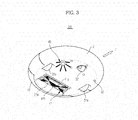
- FIG. 3 is a view schematically illustrating a bottom portion of the autonomous cleaning apparatus according to an embodiment of the present disclosure.
- the autonomous cleaning apparatus 20 includes a body 21, a driving apparatus 30, a cleaning apparatus 40, various sensors 50, and a control unit 24.
- the body 21 is provided in various shapes.
- the body 21 may be provided in the form of a cylinder. If the body 21 having a cylindrical form rotates, the body 21 has a constant rotation radius, and thus avoids contact with a surrounding obstacle, as well as changes a direction easily. In addition, the body 21 having a cylindrical form prevents from being stuck during a course of a driving because of a surrounding obstacle.
- the driving apparatus 30, the cleaning apparatus 40, various sensors 50, the display 23, and the control unit 24 may be provided on the body 21.
- the driving apparatus 30 enables the body 21 to operate on an area to be cleaned.
- the driving apparatus 30 includes a left driving wheel 31 a, a right driving wheel 31 b, and a caster 32.
- the left driving wheel 31 a and the right driving wheel 31 b are installed on a center portion of the bottom of the body 21, and the caster 32 is installed on a front portion of the bottom of the body 21 so that the autonomous cleaning apparatus 20 maintains a stable position.
- the left driving wheel 31 a and the right driving wheel 31 b are controlled such that the autonomous cleaning apparatus moves forward and backward, or changes a direction.
- the left driving wheel 31 a and the right driving wheel 31 b are equally controlled such that the autonomous cleaning apparatus 20 moves forward or backward; the left driving wheel 31 a and the right driving wheel 31 b are controlled differently such that the autonomous cleaning apparatus 20 changes a direction.
- Each of the left driving wheel 31 a, the right driving wheel 31 b, and the caster 32 is implemented as a single assembly, and detachably installed to the body 21.
- the cleaning apparatus 40 is configured to clean the bottom and the surroundings of the body 21.
- the cleaning apparatus 40 includes a brush unit 41, a side brush 45, and a first dust container 43.
- the brush unit 41 may be installed at the first opening 21 a formed on a bottom portion of the body 21.
- the brush unit 41 may be provided at a position deviated from the central portion of the body 21. That is, the brush unit 41 may be provided at a position adjacent to the left driving wheel 31 a and the right driving wheel 31b but towards a rear (R) of the body 21.
- the brush unit 41 collects the dust accumulated on the bottom of the body 21 into the first dust container 43.
- the brush unit 41 includes a roller 41 a which is rotatably provided at the first opening 21 a, and a brush 41 b which is installed on an outer portion of the roller 41 a.
- the brush 41 b which includes elastic material, stirs the dust collected on the bottom.
- the dust accumulated on the bottom passes through the first opening 21 a and then stored into the first dust container 43.
- the brush unit 41 is controlled to move on a constant rotation velocity to maintain a cleaning performance at a stable manner.
- the rotation velocity of the brush unit 41 may vary.
- the rotation velocity of the brush unit 41 when an uneven surface is to be cleaned, such as a carpet, may be reduced compared to when an even surface is to be cleaned. At this time, more current may be provided to maintain a constant rotation velocity of the brush unit 41.
- the side brush 45 may be rotatably installed on a bottom portion of the body 21.
- the side brush 45 may be provided at a position away from the central portion of the body 21, toward a front (F) of the body 21.
- the side brush 45 moves the dust collected around the body 21 to the brush unit 41.
- the side brush 45 expands a cleaning range on the bottom of the body 21 and a surrounding surface of the body 21.
- the dust moved to the brush unit 41, as described above, may be stored in the first dust container 43 through the first opening 21 a.
- the first dust container 43 may be installed on a rear portion of the body 21.
- An inlet 43' of the first dust container 43 is connected through the first opening 21 a of the body 21, and dust is introduced to the first dust container 43 via the inlet 43'.
- the first dust container 43 is divided into a large dust container 43a and a small dust container 43b.
- the brush unit 41 collects large-size dust into the large dust container 43a via the first inlet 43a', and an air blower unit 22 intakes and stores small-size, floating foreign substances, such as hair, into the small dust container 43b via a second inlet 43b'.
- a brush cleaning member 42 is provided at an adjacent portion to the second inlet 43b' and the brush cleaning member 42 filters out the foreign substances wound around the brush unit 41, and the foreign substances are stored in the small dust container 43b via the second inlet 43b' by suction force of the air blower unit 22.
- a dust detection unit 44 is installed inside the first dust container 43 to detect the amount of the dust in the first dust container 43.
- the dust detection unit 44 includes an optical sensor including a light-emitting sensor 44a and a light-receiving sensor 44b.
- an optical sensor including a light-emitting sensor 44a and a light-receiving sensor 44b.
- those of skill in the art will understand that alternative configurations of the present disclosure could employ another types of sensors to detect the amount of the dust.
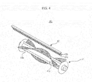
- FIG. 4 is a view schematically illustrating a brush unit and a brush cleaning member according to an embodiment of the present disclosure.
- the brush cleaning member 42 includes a first brush cleaning protrusion 42a and a second brush cleaning protrusion 42b that are protruded and slanted in an opposite direction to one another.
- the first brush cleaning protrusion 42a when the brush unit 41 rotates toward a first direction (P), makes contact with the brush 41 b to remove foreign substances wound around the brush 41 b effectively.
- the second brush cleaning protrusion 42b when the brush unit 41 rotates toward a second direction (Q), makes contact with the brush 41 b to remove foreign substances wound around the brush 41 b effectively.
- an example of foreign substances may be hair that winds around the brush unit 41 while an autonomous cleaning apparatus 20 moves for cleaning.
- the first brush cleaning protrusions 42a and the second brush cleaning protrusions 42b take turns in making contact with the brush 41 b and removing foreign substances wound around the brush 41 b.
- the brush cleaning member 42 which includes a first brush cleaning protrusion 42a and a second brush cleaning protrusion 42b may be formed in plurality lengthwise along the brush unit 41.
- the brush cleaning member 42 may also be formed at least in one row lengthwise along the brush unit 41.
- FIGS. 5 and 6 are views schematically illustrating a brush cleaning member according to an embodiment of the present disclosure.
- the first brush cleaning protrusion 42a and the second brush cleaning protrusion 42b protrude within a radius of rotation of the brush unit 41 to easily remove dust by making contact with the brush 41 b of the brush unit 41.
- the first brush cleaning protrusion 42a and the second brush cleaning protrusion 42b may be integrally formed with each other on an edge of the brush cleaning member 42.
- the brush cleaning member 42 is provided at an adjacent portion to the second inlet 43b' while protruding toward the brush unit 41.
- the dust removed from the brush unit 41 is stored in the small dust container 43b by a suction force of the air blower unit 22.
- the first brush cleaning protrusion 42a and the second brush cleaning protrusion 42b are formed on the same basal area along a rotating direction of the brush unit 41 while being spaced apart from each other.
- the first brush cleaning protrusion 42a may be provided at an adjacent portion of the second inlet 43b', and the second brush cleaning protrusions 42b may be provided on the same basal area on which the first brush cleaning protrusion 42a is provided.
- the second brush cleaning protrusion 42b may be provided at an adjacent portion of the second inlet 43b', and the first brush cleaning protrusion 42a may be provided on the same basal area on which the second brush cleaning protrusion 42b is provided.
- the first brush cleaning protrusion 42a and the second brush cleaning protrusion 42b are formed while being spaced apart from each other, the first brush cleaning protrusion 42a may protrude while being slanted toward the first direction of rotation of the brush unit 41, and the second brush cleaning protrusions 42b may protrude while being slanted toward the second direction of rotation of the brush unit 41.
- a protrusion direction of each of the brush cleaning protrusions 42a and 42b is not limited hereto. Accordingly, the extension direction of the brush cleaning protrusions 42a and 42b may be set in a direction that the foreign substances wound around the brush 41 b are easily removed in relation to each rotating direction of the brush unit 41.
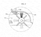
- FIGS. 7 to 9 are views schematically illustrating a cleaning motion according to the first direction of rotation of the brush unit of an embodiment of the present disclosure.
- the first brush cleaning protrusion 42a and the second brush cleaning protrusion 42b protrude within a radius of rotation of the brush unit 41.
- the brush unit 41 rotates in the first direction (P) while the brush 41 b stirs the dust accumulated on the floor.
- the accumulated dust collected as a result of such motion is stored in the first dust container 43 via the first inlet 43a'.
- the foreign substances wound around the brush 41 b may be removed by use of the first brush cleaning protrusion 42a.
- the foreign substances such as hair wound around the brush 41 b of the brush unit 41 may move to be adjacent to the first brush cleaning protrusion 42a.
- the brush 41 b of the brush unit 41 makes contact with the first brush cleaning protrusion 42a, the foreign substances wound around the brush 41 b are removed by the brush unit 41, and while the autonomous cleaning apparatus 20 moves for cleaning, the foreign substances removed from the brush unit 41 by the first brush cleaning protrusion 42a may be stored in the small dust container 43b via the second inlet 43b'.
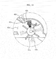
- FIGS. 10 to 12 are views schematically illustrating a cleaning motion according to the second direction of rotation of the brush unit of an embodiment of the present disclosure.
- the brush unit 41 of the autonomous cleaning apparatus 20 rotates in the second direction 2 (Q)
- foreign substances may be removed by use of the second brush cleaning protrusion 42b. That is, as the brush unit 41 rotates in the second direction, the foreign substances wound around the brush unit 41 may move to be adjacent to the second brush cleaning protrusion 42b. As the brush 41 b makes contact with the second brush cleaning protrusion 42b, the foreign substances wound around the brush 41 b are removed from the brush unit 41, and the foreign substances removed may be stored in the small dust container 43b via the second inlet 43b'.
- the autonomous apparatus 20 may intake dust while moving for cleaning, and the dust may be exhausted at the maintenance station 60 while operating.
- the brush unit 41 of the autonomous apparatus 20 rotates in the second direction. Also at this time, foreign substances wound around the brush unit 41 b may be removed from the brush unit 41 by use of the second cleaning protrusion 42b, and the removed foreign substances may be exhausted to the dust container of the maintenance station 60.
- the autonomous cleaning apparatus 20 even when the autonomous cleaning apparatus 20 is not docked into the maintenance station 60, foreign substances wound around the brush unit 41 b may be removed from the brush unit 41 by the second cleaning protrusion 42b while the brush unit 31 is rotating in the second direction. At this time, the autonomous cleaning apparatus 20 may be in a stationary status, or in a status of repeatedly moving forward and backward.
- the brush unit 41 alternately rotates in the first direction and the second direction, thereby maximizing a performance in removing foreign substances. That is, the brush unit 41 of the autonomous cleaning apparatus 20 may change a direction of a rotation of the brush unit 41 at least once in removing foreign substances wound around the brush unit 41. Since the dust that the autonomous cleaning apparatus 20 intakes is being stored into the large dust container 43a by passing through the brush unit 41 and then the first inlet 43a' of the autonomous cleaning apparatus 20, foreign substances may be wound around the brush unit 41 of the autonomous cleaning apparatus 20. At this time, by changing a rotation direction of the brush unit 41 of the autonomous cleaning apparatus 20, the foreign substances wound around the brush unit 41 of the autonomous cleaning apparatus 20 may be removed. Afterwards, the brush unit 41 of the autonomous cleaning apparatus 20 may change a direction of a rotation again toward an original direction. In this manner, the brush unit 40 of the autonomous cleaning apparatus 20 may remove foreign substances wound around the brush unit 41 while alternating the rotation direction at least once.
- the brush cleaning member 42 extended and protruded from the body 21 makes contact with the brush unit 41.
- the brush unit member 42 is formed lengthwise along the brush unit 42, and removes foreign substances wound around the brush unit 41.
- the first brush cleaning protrusion 42a and the second brush cleaning protrusion 42b protrude to pick up foreign substances such as hair, and remove the collected foreign substances around the brush unit 41 by following a direction of a rotation of the brush unit 41. That is, as the brush 41 b of the brush unit 41 makes contact with the first brush cleaning protrusion 42a and the second brush cleaning protrusion 42b when the brush unit 41 rotates in the first direction P or the second direction Q, foreign substances are picked up.
- the foreign substances move from a lower portion to a upper portion of the brush cleaning protrusions 42a and 42b when the brush 41 b of the brush unit 41 rotates, and during such process, foreign substances are removed from the brush 41 b of the brush unit 41.
- Each of the brush unit 41, the side brush 45, and the first dust container 43 may be formed as a single assembly, and may be detachably installed on the body 21.
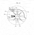
- FIG. 13 is a view schematically illustrating a foreign substance removal tool according to an embodiment of the present disclosure.
- a foreign substance removal tool 46 may be formed as a single assembly, and may be detachably installed on the body 21.
- the brush unit 41 may be also detachably provided on the body 21.
- the brush unit 41 includes a roller 41 a and coupling protrusion units 41 c coupled to both ends of the roller 41 a.
- the coupling protrusion unit 41 c protrudes outward from both ends of the roller 41 a.
- the body 21 includes a coupling slot unit 21c to which the coupling protrusion unit 41c is coupled.
- the foreign substance removal tool 46 includes a coupling protrusion unit which is coupled to a coupling slot unit of the body 21 such that the foreign substance removal tool 46 is coupled to the body 21.
- the foreign substance removal tool 46 when the brush unit 41 is coupled to the body 21, the foreign substance removal tool 46 is coupled to a lower portion of a brush unit while being adjacent to the body 21. Meanwhile, the foreign substance removal tool 46 may cover the opening 21 a of the autonomous cleaning unit 20 while forming the same curvature as a rotating radius of the brush unit 41. Accordingly, the foreign substances removed from the brush unit 41 are prevented from being exhausted to an outside of the autonomous cleaning apparatus 20.
- the foreign substance removal tool 46 is provided with a brush cleaning member 46c that protrudes toward a predetermined direction. By making contact with the brush unit 41 being rotating, the foreign substance removal tool 46 removes foreign substances wound around the brush unit 41.
- the brush cleaning member 46c may be provided with a first brush cleaning protrusion 46a and a second brush cleaning protrusion 46b which slantingly protrude in an opposite direction to each other.
- the brush unit 41 may rotate in a first direction P or second direction Q, or alternately rotate in the first direction P and the second direction Q to remove foreign substances wound around the brush unit 41 by use of the brush cleaning member 46c.
- the brush cleaning member 46c which is provided on the foreign substance removal tool 46, may be adjacent to a coupling position of the foreign substance removal tool 46 and the body 21 while protruding toward the brush unit 41.
- the brush cleaning member 46c may be formed in the center portion of the foreign substance removal tool 46 lengthwise along the brush unit 41.
- the first brush cleaning protrusion 46a and the second brush cleaning protrusion 46b may be integrally formed with each other on an end portion of the brush cleaning member 46c, or may be separately formed on a basal area while being spaced apart from each other.
- the first brush cleaning protrusion 46a and the second brush cleaning protrusion 46b are separately formed while being spaced apart from each other, the first brush cleaning protrusion 46a is diagonally slanted toward the first direction P of rotation of the brush unit 41, and the second brush cleaning protrusion 46b diagonally slanted toward the second direction Q of rotation of the brush unit 41.
- a control unit 24 determines whether to remove foreign substances wound around the brush unit 41, and if it is determined to remove foreign substances, the control unit 24 may autonomously execute a foreign substance removal mode.
- the foreign substance removal mode represents a motion to remove foreign substances wound around the brush unit 41 by use of the brush cleaning member 42 while the brush unit 41 repeatedly rotates in the first direction or the second direction, or the brush unit 41 repeatedly alternates rotating in the first direction and the second direction.
- the control unit 24 may rotate the brush unit 41 to the first direction and the second direction alternately to remove foreign substances wound around the brush unit 41.
- control unit 24 after determining whether to remove foreign substances, may control the display 23 to display information about the determination, and also to display an execution status of a foreign substance removal mode.
- a user may proceed to a foreign substance removal mode by installing the foreign substance removal tool 46 on the bottom portion of the autonomous cleaning apparatus 20. At this time, the user may remove foreign substances by use of the foreign substance removal tool 46 installed on the bottom portion of the autonomous cleaning apparatus 20 without having to separate the brush from the autonomous cleaning apparatus 20.
- the autonomous cleaning apparatus 20 may store the foreign substances, which are removed from the brush unit 41 by the brush cleaning protrusion along with rotation of the brush unit, in a storage (not shown) in the foreign substance removal tool 46.
- the brush cleaning protrusion may be provided in a radius of rotation of the brush or may be installed on the foreign substance removal tool 46.
- control unit 24 may detect the amount of foreign substances wound around a brush unit 41 and determines whether to remove the foreign substances based on the detected amount of foreign substances.
- the optical sensor may include a light-emitting sensor 44a and a light-receiving sensor 44b.
- the optical sensor may be disposed such that a signal emitted from the light-emitting sensor 44a is directly transmitted to the light-receiving sensor 44b.
- the light-emitting sensor 44a and the light-receiving sensor 44b may be implemented using a photo diode or a photo transistor. In such case, according to the amount of energy detected by the photo diode or the photo transistor, the amount of foreign substances wound around the brush 41 b is determined. That is, if foreign substances are accumulated, the amount of energy detected by a photo diode or a photo transistor may be reduced significantly. After comparing the amount of energy detected to a pre-established standard value and found that the amount of energy is less than a predetermined value, it is determined that foreign substances are to be removed. That is, the light-emitting sensor 44a and the light-receiving sensor 44b, which includes a photo diode or a photo transistor, are affected by an external disturbance.
- a structure such as an optical guide or a slit that guides signals from a light-emitting sensor 44a and a light-receiving sensor 44b, detects the presence of dust more accurately.
- a control unit 24 determines the amount of foreign substances wound around the brush unit 41 based on loads on the motor which operates the brush unit 41 and determines whether to remove the foreign substances wound around a brush unit 41 based on the amount of the foreign substances detected.
- a rotating speed of the brush unit 41 decreases while loads on a motor increase. If the load of the motor increases, the amount of current provided to the motor increases. Accordingly, a control unit 24 detects the load applied to the motor based on the amount of currents provided to the motor. Therefore, in a case when the load on the motor increase, the control unit 24 determines whether to remove foreign substances wound around the brush unit 41.
- a predetermined value is compared with the amount of current provided to the motor, and if the amount of current provided to the motor is less than a predetermined value, the control unit 24 determines not to remove foreign substances, and if the amount of currents provided to a motor is greater than a predetermined value, the control determine to remove foreign substances.
- control unit 24 may determine, based on the input by a user, that whether foreign substances to be removed.
- An input by a user may take place via a switch which is provided on the body 21 of the autonomous cleaning apparatus 20.
- an input by a user may take place via a remote control apparatus which interacts with the autonomous cleaning apparatus 20. That is, a user, via a switch which is provided on a remote control apparatus, may input a foreign substance removal mode to control the autonomous cleaning apparatus 20 to execute a foreign substance removal mode.
- a user may input a command in order for the autonomous cleaning apparatus 20 to execute a foreign substance removal mode during a particular period of time at regular time intervals.
- the control unit 24, based on the input made by a user may execute a foreign substance removal mode, and display an indicator on the display 23 when the foreign substance removal mode is completed.
- the brush unit 41 rotates in the first direction P, and foreign substances wound around the brush 41 b of the brush unit 41 such as hair move to be adjacent to the first brush cleaning protrusion 42a. As the first brush cleaning protrusion 42a make contact with the brush 41 b of the brush unit 41, foreign substances wound around the brush 41 b are removed from the brush unit 41.
- the foreign substance removal mode may be executed while repeatedly rotating the brush unit 41 in the first direction P or the second direction Q, or repeatedly changing a rotational direction of the brush unit 41 between the first direction P and the second direction Q.
- the foreign substance removal mode may be executed while the autonomous cleaning apparatus 20 is in a stationary status, or in a status of the autonomous cleaning apparatus 20 repeatedly moving forward and backward.
- the autonomous cleaning apparatus 20 determines that foreign substances to be removed, the autonomous cleaning apparatus 20 moves onto the maintenance station 60 and enter a foreign substance removal mode while the autonomous cleaning apparatus 20 is in a stationary status.
- the autonomous cleaning apparatus 20 may use its suction force or a suction force of the maintenance station 60.
- an air blower unit inside the housing 61 of the maintenance station 60 (not shown) operates, and the maintenance station 60 intakes foreign substances, which are filtered from the autonomous cleaning apparatus 20.
- control unit 24 may recognize the foreign substance removal tool 46 being coupled to a lower portion of the brush unit 41.
- the control unit 24 may use a micro switch, an optical sensor, or a magnetic sensor in recognizing the foreign substance removal tool 46 being coupled to a lower portion of the brush unit 41.
- the micro switch is a microscopic switch that may supply and shut off a relatively large amount of current by using a small force, and may be disposed at the coupling slot unit 21 c of the body 21.
- a force generated when the coupling protrusion unit 41 c of the foreign substance removal tool 46 is coupled to the coupling slot unit 21c of the body 21 a traveling contact is instantly changed for a current to flow through.
- the control unit 24, based on the current flowing through, may recognize the foreign substance removal tool 46 being coupled to a lower portion of the brush unit 41.
- an infrared light sensor is disposed at a coupling slot unit 21c of the body 21, and it is determined whether an infrared light emitted from a light-emitting unit of the infrared light sensor is received by a light-receiving unit. If an infrared light sensor is received by a light-receiving unit, the foreign substance removal tool 46 is recognized as no-disturbance status and as not being coupled to the body 21. If an infrared light sensor is received by a light-receiving unit, the foreign substance removal tool 46 is recognized as being coupled to the body 21.
- a magnetic sensor may be disposed at the coupling slot unit 21 c of the body 21, and a magnet may be disposed at the coupling protrusion unit 41 c of the foreign substance removal tool 46.
- the magnetic sensor may detect a magnetic field generated by the magnet disposed at the coupling protrusion unit 41 c of the foreign substance removal tool 46, and recognize if the foreign substance removal tool 46 is coupled to the body 21 based on the intensity of the magnetic field.
- the control unit 24 may autonomously execute a foreign substance removal mode, or execute a foreign substance removal mode based on the input made by a user.
- the various sensors 50 which are installed on the body 21 are used for detecting obstacles.
- the sensor may be implemented using contact-type sensors or proximity sensors.
- a bumper 51 which is installed on the front (F) of the body 21 may be used to detect a front side obstacle, such as a wall.
- an infrared light sensor or an ultrasonic wave sensor may be used to detect a front side obstacle.
- an infrared light sensor 52 (or an ultrasonic wave sensor) which is installed on a lower portion of the body 21 may be used to detect a condition of a floor, such as stairs.
- a plurality of infrared light sensors 52 may be installed on a bottom portion of the body 21 along a circumference of the body 21 in a semicircular arc shape.
- the location of the infrared light sensors is not limited thereto.
- various sensors may installed on the body 21 to send information on the status of an autonomous cleaning apparatus 20.
- the control unit 24 receives signals from the various sensors 50 and controls the driving unit 30 and the cleaning unit 40 to control the autonomous cleaning apparatus 20 efficiently.
- FIG. 14 is a flow chart schematically illustrating a method of controlling the autonomous cleaning apparatus according to an embodiment of the present disclosure.
- the autonomous cleaning apparatus rotates the brush unit and collects dust accumulated on the bottom of the body into the dust container.
- foreign substances in accumulated dust may disrupt the rotation of the brush unit while wound around the brush, and may reduce a cleaning performance of the autonomous cleaning apparatus. Therefore, prior to removing foreign substances wound around the brush unit, whether to remove foreign substances wound around the brush unit is determined (S10).
- a method of determining to remove foreign substances is to detect the amount of foreign substances wound around the brush unit based on the amount of energy detected by a dust detection unit 44 including an optical sensor installed on a wall of an opening of the body, or based on the load on the motor which operates the brush unit. Whether to remove the foreign substances is determined based on the amount of the foreign substances detected.
- an input by a user may take place via a switch which is provided on the body of the autonomous cleaning apparatus, or an input by a user may take place via a remote control apparatus which interacts with the autonomous cleaning apparatus.
- the brush cleaning member 42 including the first brush cleaning protrusion 42a and the second brush cleaning protrusion 42b, which are slantedly protruding in an opposite direction to each other, removes foreign substances wound around the brush unit (S20).
- the foreign substances such as hair wound around the brush 41 b of the brush unit 41 may move to be adjacent to the first brush cleaning protrusion 42a.
- the brush 41 b of the brush unit 41 makes contact with the first brush cleaning protrusions 42a, the foreign substances wound around the brush 41 b are removed from a brush unit 41.
- the brush unit 41 rotates in the second direction Q, the foreign substances such as hair wound around the brush 41 b of the brush unit 41 move to be adjacent to the second brush cleaning protrusion 42b.
- the foreign substances wound around the brush 41 b are removed from the brush unit 41.
- the brush unit 41 rotates in the first direction P and the second direction Q alternately to remove the foreign substances wound around the brush unit 41. That is, the brush unit 41 of the autonomous cleaning apparatus 20 may remove foreign substances wound around the brush unit 41 while changing a direction of a rotation of a brush unit 41 at least once.
Applications Claiming Priority (2)
| Application Number | Priority Date | Filing Date | Title |
|---|---|---|---|
| US201161530019P | 2011-09-01 | 2011-09-01 | |
| KR1020110100467A KR101880089B1 (ko) | 2011-09-01 | 2011-10-04 | 로봇 청소기와 그 제어 방법 |
Publications (1)
| Publication Number | Publication Date |
|---|---|
| EP2570067A1 true EP2570067A1 (de) | 2013-03-20 |
Family
ID=46704503
Family Applications (1)
| Application Number | Title | Priority Date | Filing Date |
|---|---|---|---|
| EP12180883A Withdrawn EP2570067A1 (de) | 2011-09-01 | 2012-08-17 | Reinigungsroboter und Steuerverfahren dafür |
Country Status (4)
| Country | Link |
|---|---|
| US (1) | US20130056026A1 (de) |
| EP (1) | EP2570067A1 (de) |
| JP (1) | JP2013052238A (de) |
| CN (1) | CN102961088B (de) |
Cited By (7)
| Publication number | Priority date | Publication date | Assignee | Title |
|---|---|---|---|---|
| GB2583158A (en) * | 2019-04-17 | 2020-10-21 | Conta Sro | Vacuum cleaner head |
| EP3662804A4 (de) * | 2017-08-01 | 2021-04-28 | Toshiba Lifestyle Products & Services Corporation | Absaugungsöffnungselement und elektrisches reinigungsgerät |
| US11234568B2 (en) | 2016-09-09 | 2022-02-01 | Sharkninja Operating Llc | Agitator with hair removal |
| US11247245B2 (en) | 2017-12-27 | 2022-02-15 | Sharkninja Operating Llc | Cleaning apparatus with anti-hair wrap management systems |
| US11672393B2 (en) | 2017-12-27 | 2023-06-13 | Sharkninja Operating Llc | Cleaning apparatus with selectable combing unit for removing debris from cleaning roller |
| US11707171B2 (en) | 2017-05-26 | 2023-07-25 | Sharkninja Operating Llc | Hair cutting brushroll |
| US11925303B2 (en) | 2017-03-10 | 2024-03-12 | Sharkninja Operating Llc | Agitator with debrider and hair removal |
Families Citing this family (30)
| Publication number | Priority date | Publication date | Assignee | Title |
|---|---|---|---|---|
| JP5771885B2 (ja) * | 2013-06-03 | 2015-09-02 | みこらった株式会社 | 電気掃除装置 |
| GB201404917D0 (en) * | 2014-03-19 | 2014-04-30 | Dyson Technology Ltd | Cleaner head |
| CN105268663B (zh) * | 2014-07-22 | 2020-06-02 | 株式会社光和 | 清扫装置、空气过滤器的清扫装置、吸尘器和吸尘器具 |
| JP6865499B2 (ja) * | 2014-07-22 | 2021-04-28 | 株式会社コーワ | 清掃装置、エアフィルターの清掃装置、掃除機及び掃除具 |
| JP6522905B2 (ja) * | 2014-08-20 | 2019-05-29 | 東芝ライフスタイル株式会社 | 電気掃除機 |
| GB2529819B (en) * | 2014-09-02 | 2017-06-14 | Dyson Technology Ltd | Cleaner head |
| EP3795048A1 (de) | 2014-12-24 | 2021-03-24 | iRobot Corporation | Evakuierungsstation |
| JP6552856B2 (ja) * | 2015-03-26 | 2019-07-31 | 東芝ライフスタイル株式会社 | 掃除装置 |
| CN105433872B (zh) * | 2015-04-15 | 2019-02-12 | 小米科技有限责任公司 | 智能清洁设备及其清扫组件 |
| CN105433880A (zh) * | 2015-04-15 | 2016-03-30 | 小米科技有限责任公司 | 智能清洁设备及其滚刷仓筒、相应的滚刷清洁方法及装置 |
| JP6539504B2 (ja) * | 2015-06-05 | 2019-07-03 | 株式会社マキタ | 自走式集塵ロボット |
| JP2017074258A (ja) * | 2015-10-15 | 2017-04-20 | 日立アプライアンス株式会社 | 吸口及びそれを用いた自律走行型掃除機 |
| CA3223536A1 (en) | 2015-10-21 | 2017-04-27 | Sharkninja Operating Llc | Surface cleaning head with leading roller |
| US11647881B2 (en) | 2015-10-21 | 2023-05-16 | Sharkninja Operating Llc | Cleaning apparatus with combing unit for removing debris from cleaning roller |
| US9902477B1 (en) | 2016-11-04 | 2018-02-27 | Aqua Products, Inc. | Drive module for submersible autonomous vehicle |
| US10301837B2 (en) | 2016-11-04 | 2019-05-28 | Aqua Products, Inc. | Drive module for submersible autonomous vehicle |
| US11202542B2 (en) | 2017-05-25 | 2021-12-21 | Sharkninja Operating Llc | Robotic cleaner with dual cleaning rollers |
| DE102017119216A1 (de) * | 2017-08-22 | 2019-02-28 | Vorwerk & Co. Interholding Gmbh | Kehrbürste für ein sich selbsttätig fortbewegendes Reinigungsgerät |
| KR20190054517A (ko) * | 2017-11-13 | 2019-05-22 | 삼성전자주식회사 | 청소기 |
| US11382479B2 (en) * | 2017-11-17 | 2022-07-12 | Milwaukee Electric Tool Corporation | Floor cleaning machine |
| CN108816826A (zh) * | 2018-06-01 | 2018-11-16 | 嘉兴宇乾环保科技有限公司 | 一种工业食品废渣收集装置 |
| KR102520318B1 (ko) | 2018-10-19 | 2023-04-10 | 샤크닌자 오퍼레이팅 엘엘씨 | 표면 처리 장치용 교란기 및 이를 갖는 표면 장치 |
| CN109793462B (zh) * | 2019-01-21 | 2021-04-20 | 浙江绿宇装饰有限公司 | 室内装饰装修用自动化铺设台阶地毯机械及其清扫装置 |
| CN112386163B (zh) * | 2019-08-19 | 2022-03-18 | 添可智能科技有限公司 | 清洁装置和切割组件控制系统 |
| JP6823132B2 (ja) * | 2019-09-10 | 2021-01-27 | 日立グローバルライフソリューションズ株式会社 | 自律走行型掃除機 |
| CN216569815U (zh) * | 2020-09-02 | 2022-05-24 | 尚科宁家运营有限公司 | 用于机器人清洁器的对接站、机器人清洁器以及系统 |
| CN112617684B (zh) * | 2020-12-16 | 2022-11-11 | 江苏美的清洁电器股份有限公司 | 基座及清洁设备 |
| CN112934767A (zh) * | 2021-01-26 | 2021-06-11 | 上海稳巢信息科技有限公司 | 一种排列式放电针清洁控制系统 |
| CN116076949A (zh) * | 2021-11-05 | 2023-05-09 | 追觅创新科技(苏州)有限公司 | 清洁设备的控制方法、及清洁设备 |
| CN115012349A (zh) * | 2022-08-08 | 2022-09-06 | 杰瑞环境科技有限公司 | 滚刷清洁机构、滚刷装置和清洁车 |
Citations (2)
| Publication number | Priority date | Publication date | Assignee | Title |
|---|---|---|---|---|
| US20030204923A1 (en) * | 2002-05-02 | 2003-11-06 | Kazuo Nakamura | Cleaning implement |
| EP2443978A2 (de) * | 2010-10-25 | 2012-04-25 | Samsung Electronics Co., Ltd. | Selbstständige Reinigungsvorrichtung |
Family Cites Families (9)
| Publication number | Priority date | Publication date | Assignee | Title |
|---|---|---|---|---|
| US1706039A (en) * | 1922-10-26 | 1929-03-19 | Bissell Carpet Sweeper Co | Carpet sweeper with brush-cleaning device |
| US2701377A (en) * | 1949-01-17 | 1955-02-08 | Tennant Co G H | Rotary brush power sweeper |
| US4041567A (en) * | 1975-04-10 | 1977-08-16 | The Scott & Fetzer Company | Combination sweeping-scrubbing apparatus |
| JP2005211365A (ja) * | 2004-01-30 | 2005-08-11 | Funai Electric Co Ltd | 自律走行ロボットクリーナー |
| JP2005224263A (ja) * | 2004-02-10 | 2005-08-25 | Funai Electric Co Ltd | 自走式掃除機 |
| US7578020B2 (en) * | 2005-06-28 | 2009-08-25 | S.C. Johnson & Son, Inc. | Surface treating device with top load cartridge-based cleaning system |
| KR100779193B1 (ko) * | 2006-12-11 | 2007-11-23 | 주식회사 대우일렉트로닉스 | 로봇청소기 및 로봇청소기 제어방법 |
| EP1980188B1 (de) * | 2007-03-27 | 2012-11-14 | Samsung Electronics Co., Ltd. | Reinigungsroboter mit verbessertem Staubsammler |
| JP5199767B2 (ja) * | 2008-07-22 | 2013-05-15 | 花王株式会社 | 清掃具 |
-
2012
- 2012-08-17 EP EP12180883A patent/EP2570067A1/de not_active Withdrawn
- 2012-08-30 US US13/599,376 patent/US20130056026A1/en not_active Abandoned
- 2012-08-30 JP JP2012189711A patent/JP2013052238A/ja active Pending
- 2012-08-31 CN CN201210319703.1A patent/CN102961088B/zh active Active
Patent Citations (2)
| Publication number | Priority date | Publication date | Assignee | Title |
|---|---|---|---|---|
| US20030204923A1 (en) * | 2002-05-02 | 2003-11-06 | Kazuo Nakamura | Cleaning implement |
| EP2443978A2 (de) * | 2010-10-25 | 2012-04-25 | Samsung Electronics Co., Ltd. | Selbstständige Reinigungsvorrichtung |
Cited By (10)
| Publication number | Priority date | Publication date | Assignee | Title |
|---|---|---|---|---|
| US11234568B2 (en) | 2016-09-09 | 2022-02-01 | Sharkninja Operating Llc | Agitator with hair removal |
| GB2568012B (en) * | 2016-09-09 | 2022-08-10 | Sharkninja Operating Llc | Agitator with hair removal |
| US11925303B2 (en) | 2017-03-10 | 2024-03-12 | Sharkninja Operating Llc | Agitator with debrider and hair removal |
| US11707171B2 (en) | 2017-05-26 | 2023-07-25 | Sharkninja Operating Llc | Hair cutting brushroll |
| EP3662804A4 (de) * | 2017-08-01 | 2021-04-28 | Toshiba Lifestyle Products & Services Corporation | Absaugungsöffnungselement und elektrisches reinigungsgerät |
| US11247245B2 (en) | 2017-12-27 | 2022-02-15 | Sharkninja Operating Llc | Cleaning apparatus with anti-hair wrap management systems |
| US11633764B2 (en) | 2017-12-27 | 2023-04-25 | Sharkninja Operating Llc | Cleaning apparatus with anti-hair wrap management systems |
| US11672393B2 (en) | 2017-12-27 | 2023-06-13 | Sharkninja Operating Llc | Cleaning apparatus with selectable combing unit for removing debris from cleaning roller |
| GB2583158A (en) * | 2019-04-17 | 2020-10-21 | Conta Sro | Vacuum cleaner head |
| GB2583158B (en) * | 2019-04-17 | 2023-04-12 | Conta Sro | Vacuum cleaner head |
Also Published As
| Publication number | Publication date |
|---|---|
| JP2013052238A (ja) | 2013-03-21 |
| US20130056026A1 (en) | 2013-03-07 |
| CN102961088A (zh) | 2013-03-13 |
| CN102961088B (zh) | 2017-09-05 |
Similar Documents
| Publication | Publication Date | Title |
|---|---|---|
| EP2570067A1 (de) | Reinigungsroboter und Steuerverfahren dafür | |
| KR101880089B1 (ko) | 로봇 청소기와 그 제어 방법 | |
| US11382478B2 (en) | Mobile floor-cleaning robot with floor-type detection | |
| TWI789624B (zh) | 一種智慧清潔設備 | |
| EP2438843B1 (de) | Einheit zur Messung der Staubeinströmung und Reinigungsroboter damit | |
| KR101460534B1 (ko) | 로봇 청소기 | |
| EP2253258B1 (de) | Selbständige Reinigungsmaschine | |
| JP7012238B2 (ja) | 自律走行型掃除機 | |
| EP3205250B1 (de) | Autonomer beweglicher reiniger | |
| JP2014023930A (ja) | ロボット掃除機 | |
| US10271705B2 (en) | Autonomous travel-type cleaner | |
| TWI769511B (zh) | 清潔元件及智慧清潔設備 | |
| KR101938703B1 (ko) | 로봇 청소기 및 그 제어방법 | |
| KR20120100682A (ko) | 먼지 감지 유닛 및 이를 포함하는 로봇 청소기 | |
| CN215838851U (zh) | 基站和清洁机器人系统 | |
| CN215838854U (zh) | 基站和清洁机器人系统 | |
| KR20140041229A (ko) | 로봇청소기 | |
| KR100863248B1 (ko) | 자동 주행 청소기 및 그 제어방법 | |
| WO2017134705A1 (ja) | 自律走行型掃除機、その補助ブラシおよび自律走行型掃除機を備える掃除機システム | |
| KR20150096641A (ko) | 먼지 유입 감지 유닛 및 이를 구비하는 로봇 청소기 | |
| CN216135813U (zh) | 基站和清洁机器人系统 | |
| CN114601397B (zh) | 基站和清洁机器人系统 | |
| EP4292504A1 (de) | Vibrierender mopp und automatische reinigungsvorrichtung | |
| EP4292497A1 (de) | Automatische reinigungsvorrichtung | |
| KR20140015099A (ko) | 로봇청소기 |
Legal Events
| Date | Code | Title | Description |
|---|---|---|---|
| PUAI | Public reference made under article 153(3) epc to a published international application that has entered the european phase |
Free format text: ORIGINAL CODE: 0009012 |
|
| AK | Designated contracting states |
Kind code of ref document: A1 Designated state(s): AL AT BE BG CH CY CZ DE DK EE ES FI FR GB GR HR HU IE IS IT LI LT LU LV MC MK MT NL NO PL PT RO RS SE SI SK SM TR |
|
| AX | Request for extension of the european patent |
Extension state: BA ME |
|
| 17P | Request for examination filed |
Effective date: 20130918 |
|
| RBV | Designated contracting states (corrected) |
Designated state(s): AL AT BE BG CH CY CZ DE DK EE ES FI FR GB GR HR HU IE IS IT LI LT LU LV MC MK MT NL NO PL PT RO RS SE SI SK SM TR |
|
| GRAP | Despatch of communication of intention to grant a patent |
Free format text: ORIGINAL CODE: EPIDOSNIGR1 |
|
| INTG | Intention to grant announced |
Effective date: 20180208 |
|
| GRAJ | Information related to disapproval of communication of intention to grant by the applicant or resumption of examination proceedings by the epo deleted |
Free format text: ORIGINAL CODE: EPIDOSDIGR1 |
|
| INTC | Intention to grant announced (deleted) | ||
| 17Q | First examination report despatched |
Effective date: 20180405 |
|
| STAA | Information on the status of an ep patent application or granted ep patent |
Free format text: STATUS: THE APPLICATION IS DEEMED TO BE WITHDRAWN |
|
| 18D | Application deemed to be withdrawn |
Effective date: 20200114 |