EP2568056A2 - Hochfeste und hochzähe ultrafeine drahtstange und herstellungsverfahren dafür - Google Patents
Hochfeste und hochzähe ultrafeine drahtstange und herstellungsverfahren dafür Download PDFInfo
- Publication number
- EP2568056A2 EP2568056A2 EP11777598A EP11777598A EP2568056A2 EP 2568056 A2 EP2568056 A2 EP 2568056A2 EP 11777598 A EP11777598 A EP 11777598A EP 11777598 A EP11777598 A EP 11777598A EP 2568056 A2 EP2568056 A2 EP 2568056A2
- Authority
- EP
- European Patent Office
- Prior art keywords
- wire rod
- strength
- ultra
- toughness
- fine grained
- Prior art date
- Legal status (The legal status is an assumption and is not a legal conclusion. Google has not performed a legal analysis and makes no representation as to the accuracy of the status listed.)
- Granted
Links
Images


Classifications
-
- C—CHEMISTRY; METALLURGY
- C21—METALLURGY OF IRON
- C21D—MODIFYING THE PHYSICAL STRUCTURE OF FERROUS METALS; GENERAL DEVICES FOR HEAT TREATMENT OF FERROUS OR NON-FERROUS METALS OR ALLOYS; MAKING METAL MALLEABLE, e.g. BY DECARBURISATION OR TEMPERING
- C21D9/00—Heat treatment, e.g. annealing, hardening, quenching or tempering, adapted for particular articles; Furnaces therefor
- C21D9/52—Heat treatment, e.g. annealing, hardening, quenching or tempering, adapted for particular articles; Furnaces therefor for wires; for strips ; for rods of unlimited length
-
- C—CHEMISTRY; METALLURGY
- C21—METALLURGY OF IRON
- C21D—MODIFYING THE PHYSICAL STRUCTURE OF FERROUS METALS; GENERAL DEVICES FOR HEAT TREATMENT OF FERROUS OR NON-FERROUS METALS OR ALLOYS; MAKING METAL MALLEABLE, e.g. BY DECARBURISATION OR TEMPERING
- C21D8/00—Modifying the physical properties of ferrous metals or ferrous alloys by deformation combined with, or followed by, heat treatment
- C21D8/06—Modifying the physical properties of ferrous metals or ferrous alloys by deformation combined with, or followed by, heat treatment during manufacturing of rods or wires
-
- C—CHEMISTRY; METALLURGY
- C22—METALLURGY; FERROUS OR NON-FERROUS ALLOYS; TREATMENT OF ALLOYS OR NON-FERROUS METALS
- C22C—ALLOYS
- C22C38/00—Ferrous alloys, e.g. steel alloys
- C22C38/02—Ferrous alloys, e.g. steel alloys containing silicon
-
- C—CHEMISTRY; METALLURGY
- C22—METALLURGY; FERROUS OR NON-FERROUS ALLOYS; TREATMENT OF ALLOYS OR NON-FERROUS METALS
- C22C—ALLOYS
- C22C38/00—Ferrous alloys, e.g. steel alloys
- C22C38/04—Ferrous alloys, e.g. steel alloys containing manganese
-
- C—CHEMISTRY; METALLURGY
- C21—METALLURGY OF IRON
- C21D—MODIFYING THE PHYSICAL STRUCTURE OF FERROUS METALS; GENERAL DEVICES FOR HEAT TREATMENT OF FERROUS OR NON-FERROUS METALS OR ALLOYS; MAKING METAL MALLEABLE, e.g. BY DECARBURISATION OR TEMPERING
- C21D2211/00—Microstructure comprising significant phases
- C21D2211/003—Cementite
-
- C—CHEMISTRY; METALLURGY
- C21—METALLURGY OF IRON
- C21D—MODIFYING THE PHYSICAL STRUCTURE OF FERROUS METALS; GENERAL DEVICES FOR HEAT TREATMENT OF FERROUS OR NON-FERROUS METALS OR ALLOYS; MAKING METAL MALLEABLE, e.g. BY DECARBURISATION OR TEMPERING
- C21D2211/00—Microstructure comprising significant phases
- C21D2211/005—Ferrite
Definitions
- the present invention relates to a high-strength, high-toughness wire rod, and more particularly, to a wire rod having excellent strength and toughness obtained by control of the microstructure thereof, and a method of manufacturing the same.
- a controlled rolling technique in which rolling is performed at a temperature appropriate for minimizing grain size, has also been used, and, as a result, a diameter of ferrite grains has been able to be refined to about 20 ⁇ m.
- TMCP Thermomechanical Control Process
- all of the foregoing grain refinement techniques may be suitable for producing steel plates, but may be difficult to apply to the production of wire rods. That is, since a wire rod may have a very high cross-section reduction rate in comparison to that of a thick steel plate, a rolling speed may be relatively fast, control of a cooling rate may not be facilitated, and in particular, with respect to water cooling, surface defects may be generated by the formation of martensite grains on the surface thereof. Therefore, the TMCP having a key role in controlling the rolling speed and the cooling rate may not be suitable for wire rods and a manufacturing technique suitable for wire rods has also been required.
- Patents related to a technique of manufacturing a fine grained, high-strength, high-toughness wire rod include Japanese Patent Application Laid-Open Publication Nos. 2009-62574 , 2009-138251 , and 2009-132958 . These patents may be limited to a method of obtaining a segmented ferrite and cementite structure through fractures in cementite grains by performing high reduction rolling, in addition to the addition of alloying elements, a cooling rate change, and controlling of alloying elements and cooling rates.
- segmented ferrite and cementite structure there may be an advantage in that segmented ferrite grains act as fine precipitate hardening materials to significantly increase the strength of a wire rod, but there may also be disadvantages, in that a decrease in ductility may inevitably be accompanied by an increase in strength according to the Hall-Petch equation.
- a fine grained wire rod manufactured by using a powder metallurgy method using fine powder.
- a wire rod manufactured in a powder metallurgy scheme may have a limitation in its use and may have a disadvantage in that its strength may be decreased due to a decrease in sinterability of fine particles thereof during sintering.
- An aspect of the present invention provides a wire rod securing high strength and high toughness through the promotion of grain refinement without the addition of alloying elements and a method of manufacturing thereof.
- a carbon steel wire rod having a microstructure including: a ferrite structure having an area fraction of 60% or more; and a cementite structure as a remainder, wherein an average grain diameter of ferrite grains is 15 ⁇ m or less.
- a method of manufacturing an ultra-fine grained, high-strength, high-toughness wire rod through heating a bloom or billet, wire-rod rolling, cooling, and winding including: cooling a wire rod subjected to the wire-rod rolling to a temperature ranging from 150°C to 350°C; and then rapid cooling the wire rod to a temperature of -100°C or less.
- an ultra-fine grained, high-strength, high toughness wire rod able to secure tensile strength and elongation on the level of alloy steel may be provided by using carbon steel without an alloying element included therein. Since relatively expensive alloying components, such as titanium (Ti), niobium (Nb), vanadium (V), and chromium (Cr), may not be added thereto, cost competitiveness may be secured and a technique related to manufacturing of an ultra-fine grained wire rod, commercialized by using a powder metallurgy method, may be secured.
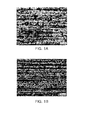
- FIGS. 1(a) and 1(b) are micrographs respectively showing a microstructure of Comparative Example 1 and a microstructure of Inventive Example 1 of Steel 1 according to Example 1 of the present invention
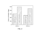
- FIG. 2 is a graph showing the results of tensile strength measurements for Comparative Examples and Inventive Examples of Steels 1 and 2 according to Example 1 of the present invention
- FIGS. 3(a) and 3(b) are an electron backscattered diffraction (EBSD) image and a micrograph of Inventive Example 2 of Steel 2 according to Example 1 of the present invention, respectively;
- FIGS. 4(a) and 4(b) are graphs respectively showing mechanical properties after drawing and annealing wire rods of Comparative Example 2 and Inventive Example 2 of Steel 2 according to Example 2 of the present invention.
- the inventors of the present invention conducted a great deal of research into a method of manufacturing a high-strength, high-toughness carbon steel wire rod without using a ferro alloy containing relatively expensive alloying elements, such as titanium (Ti), niobium (Nb), and vanadium (V), added thereto.
- a ferro alloy containing relatively expensive alloying elements such as titanium (Ti), niobium (Nb), and vanadium (V), added thereto.
- the inventors of the present invention developed a wire rod having a microstructure including: a ferrite structure having an area fraction of 60% or more; and a cementite structure as a remainder, wherein an average grain diameter of ferrite grains is 15 ⁇ m or less. Accordingly, the inventors of the present invention understood that high strength and high toughness of a wire rod may be achieved, and thus, completed the present invention.
- the wire rod of the present invention includes ferrite grains having an area fraction of 60% or more and cementite grains as a remainder.
- the fraction of ferrite grains is less than 60%, ductility decreases due to a decrease in the fraction of ferrite grains and thus, a balance of strength and toughness is deteriorated due to an increase in strength according to the Hall-Petch equation. Therefore, the fraction of ferrite grains may be 60% or more.
- the wire rod of the present invention may have ferrite grains having an average grain diameter of 15 ⁇ m or less. In the case that a size of ferrite grains is reduced, a specific surface area of the grain increases. Therefore, strength thereof may increase, but ductility may not decrease by the smooth action of a slip system. Accordingly, the wire rod of the present invention may secure high tensile strength and simultaneously, may secure ductility having a high elongation.
- an effect of increasing strength may not only be insignificant, but toughness and ductility may also decrease due to a decrease in the fraction of ferrite grains per unit area and the effect of increasing strength due to the refinement of ferrite grains may also not be secured.
- the ferrite grains in the wire rod of the present invention may have a bainitic shape. Ferrite grains having such shape are denoted as "bainitic ferrite". Bainitic ferrite has an acicular shape and is formed of a structure in a lath phase. The bainitic ferrite does not include internal precipitates and is formed of parallel lath groups having a specific habit plane with respect to austenite, a matrix phase. Since all the lath groups have the same variant, a misorientation therebetween may be relatively low, and thus, a low angle grain boundary to be described later may be formed.
- the wire rod of the present invention may promote an increase in the fraction of ferrite grains in comparison to that of general ferrite grains due to the inclusion of bainitic ferrite grains and thus, may have an effect of simultaneously increasing toughness, ductility, and strength.
- the microstructure of the wire rod of the present invention may have a crystal orientation measured by electron backscattered diffraction (EBSD) of 30 degrees or less.
- EBSD electron backscattered diffraction
- the crystal orientation is 30 degrees or less, it may be denoted as a low angle grain boundary. Since the wire rod of the present invention may have low angle grain boundaries, a fraction of fine ferrite grains may be increased, and thus, strength may not only be improved, but toughness and ductility may also be increased. Therefore, a structure able to improve mechanical properties may be formed.
- a composition of the wire rod of the present invention may include 0.15 wt% to 0.5 wt% of carbon (C), 0.1 wt% to 0.2 wt% of silicon (Si), and 0.1 wt% to 0.7 wt% of manganese (Mn).
- the composition may include iron (Fe) as well as other unavoidable impurities as a remainder.
- Other components may be added in addition to the foregoing components, but the addition of the other components does not affect the overall technical idea of the present invention.
- the wire rod of the present invention may have a tensile strength of 1100 MPa or more and an elongation of 20% or more, and may have an ECO-index (tensile strength ⁇ elongation), representing the interrelationship of strength and ductility, of 2000 or more.
- a microstructure of the wire rod may be controlled according to controlling a cooling rate after rolling of the wire rod during a manufacturing process thereof. Therefore, an embodiment of manufacturing the wire rod of the present invention through controlling the cooling rate will be described in detail.
- a bloom or billet is heated and subjected to wire-rod rolling, and a wire rod is then manufactured through cooling and winding.
- a carbon steel bloom or billet is reheated at a temperature of 1100°C or more and subjected to wire-rod rolling at a temperature ranging from 900°C to 1000°C, and the carbon steel wire rod is then manufactured through winding after cooling.
- the method of manufacturing a wire rod of the present invention includes rapid cooling to a temperature ranging from -150°C to -100°C or less, after cooling the wire rod subjected to wire-rod rolling to a temperature ranging from 150°C to 350°C.
- a process of cooling the wire rod subjected to wire-rod rolling to a temperature ranging from 150°C to 350°C may be performed by using an air cooling process.
- Rapid cooling does not denote typical water cooling or air cooling, but denotes that the wire rod is rapidly cooled in the space of a few seconds. Typically, it is considered that a martensite structure is obtained when heated steel is quenched. However, the present invention deviates from this conventional idea.
- the rapid cooling is performed and thus, diffusion may be inhibited during a cooling process to prevent grain growth, and a state immediately preceding the recrystallization of the microstructure, that is, a process of grain freezing that forms laths having a sheaf-like shape in the structure as in the structure of bainite may be undertaken after rolling due to the rapid cooling.
- a microstructure composed of ferrite grains having fine grains and cementite grains may be formed.
- an ultra-fine grained structure may be formed by preventing the growth of ferrite grains through the rapid cooling, and transformation typically occurring in carbon steel may be inhibited and thus, a structure including 60% or more of ferrite grains and cementite grains as a remainder may be formed.
- the ferrite grains are formed as bainitic ferrite grains.
- a cooling rate for the rapid cooling may be in a range of 100 °C/sec to 150 °C/sec.
- the rapid cooling does not denote typical water cooling, but aims at freezing grains through a coolant to be described later. Therefore, the cooling rate must be 100 °C/sec or more and may be in a range of 100 °C/sec to 150 °C/sec.
- Liquid nitrogen and dry ice may be used as the coolant used for the rapid cooling and a polymer solution for cooling a wire rod may be used.
- the polymer solution may be formed of 15% to 30% of polyalkylene glycol (PAG) and 70% to 85% of water (H 2 O).
- the coolant may be liquid nitrogen.
- the wire rod In the rapid cooling, the wire rod is cooled to a temperature within a range of -100°C or less and may be cooled to a temperature within a range of -100°C to -150°C. In the case that the temperature is less than -150°C, a surface of the wire rod is rapidly cooled and thus, surface defects on the wire rod itself may be generated. In the case in which the temperature is greater than -100°C, a sufficient cooling effect may not be obtained and thus, control of the structure of the wire rod required in the present invention may be impossible.
- the rapid cooling may be performed by dipping the wire rod into the coolant, and at this time, a dipping time may be in a range of 1 minute to 10 minutes. In the case that the dipping time is less than 1 minute, cooling of the wire rod may be insufficient and thus, the structure required in the present invention may not be formed. In the case in which the dipping time is greater than 10 minutes, to be relatively long, the process time for manufacturing the wire rod may become relatively long and thus, productivity may decrease.
- Step 1 S45C steel (hereinafter, referred to as "Steel 1") and 45F steel (hereinafter, referred to as “Steel 2”) were prepared in accordance with American Society for Testing Materials (ASTM), and wire-rod rolling for manufacturing a wire rod was then performed thereon. Thereafter, a portion thereof was cut and cooled to a temperature of 300°C, and rapid cooling was then performed by dipping the portion in liquid nitrogen at -150°C for 5 minutes. In order to simulate winding, samples were recovered at room temperature.
- the samples subjected to the operation of the present invention were respectively categorized as Inventive Example 1 of Steel 1 and Inventive Example 2 of Steel 2.
- the samples not subjected to the rapid cooling were categorized as Comparative Example 1 of Steel 1 and Comparative Example 2 of Steel 2.
- FIGS. 1(a) and 1(b) are micrographs respectively showing a microstructure of Comparative Example 1 and a microstructure of Inventive Example 1 of Steel 1.
- the sample of Comparative Example 1 was composed of two phases including ferrite grains having a grain diameter ranging from about 35 ⁇ m to about 40 ⁇ m and cementite grains.
- Inventive Example 1 shown in FIG. 1(b) it may be confirmed that the sample was composed of ultra-fine ferrite grains shaped like bainite (bainitic ferrite grains) having a grain diameter of about 12 ⁇ m and cementite grains.
- FIG. 2 is a graph showing the results of tensile strength measurements for Comparative Examples and Inventive Examples of Steels 1 and 2. As shown in FIG. 2 , it may be confirmed in Steels 1 and 2 that tensile strengths of the Inventive Examples were increased to about 1.5 times to about 2.0 times in comparison to those of Comparative Examples. The reason for this is that grain growth may be inhibited due to the rapid cooling in Inventive Examples to thus decrease a grain size of ferrite grains.
- FIGS. 3(a) and 3(b) are an EBSD image and a micrograph of Inventive Example 2 of Steel 2, respectively. As shown in FIG. 3(a) , it may be confirmed that low angle grain boundaries having a crystal orientation of 30 degrees or less were formed in the sample of Inventive Example 2, and, as shown in FIG. 3(b) , it may be confirmed that the grain size of ferrite grains was about 12 ⁇ m or less.
- Example was performed in order to identify mechanical properties in the case that drawing was performed by using a wire rod of the present invention.
- Samples were prepared by dry drawing Comparative Example 2 of Steel 2 at a ratio of 80% and the drawn samples were respectively annealed at 500°C and 600°C to prepare annealed samples.
- Drawn wire rods were prepared by dry drawing Inventive Example 2 of Steel 2 at a ratio of 80%. Mechanical properties thereof were measured and the results thereof are presented in FIG. 4 .
- FIG. 4(a) is a graph showing mechanical properties of the dry drawn samples prepared using Comparative Example 2 and the annealed samples
- 4(b) is a graph simultaneously showing mechanical properties of the drawn wire rods prepared using Inventive Example 2.
- dislocations may multiply due to a pile-up of dislocations during dry drawing, a grain size may be decreased by heavy deformation, and simultaneously, ductility may be decreased due to an increase in dislocation density.
Landscapes
- Chemical & Material Sciences (AREA)
- Engineering & Computer Science (AREA)
- Organic Chemistry (AREA)
- Mechanical Engineering (AREA)
- Materials Engineering (AREA)
- Metallurgy (AREA)
- Thermal Sciences (AREA)
- Physics & Mathematics (AREA)
- Crystallography & Structural Chemistry (AREA)
- Manufacturing & Machinery (AREA)
- Heat Treatment Of Steel (AREA)
- Heat Treatment Of Strip Materials And Filament Materials (AREA)
- Metal Extraction Processes (AREA)
Applications Claiming Priority (2)
| Application Number | Priority Date | Filing Date | Title |
|---|---|---|---|
| KR1020100042498A KR101253822B1 (ko) | 2010-05-06 | 2010-05-06 | 초미세립 고강도 고인성 선재 및 그 제조방법 |
| PCT/KR2011/003396 WO2011139117A2 (ko) | 2010-05-06 | 2011-05-06 | 초미세립 고강도 고인성 선재 및 그 제조방법 |
Publications (3)
| Publication Number | Publication Date |
|---|---|
| EP2568056A2 true EP2568056A2 (de) | 2013-03-13 |
| EP2568056A4 EP2568056A4 (de) | 2015-07-08 |
| EP2568056B1 EP2568056B1 (de) | 2016-11-30 |
Family
ID=44904244
Family Applications (1)
| Application Number | Title | Priority Date | Filing Date |
|---|---|---|---|
| EP11777598.1A Not-in-force EP2568056B1 (de) | 2010-05-06 | 2011-05-06 | Hochfeste und hochzähe ultrafeine drahtstange und herstellungsverfahren dafür |
Country Status (5)
| Country | Link |
|---|---|
| US (1) | US9322075B2 (de) |
| EP (1) | EP2568056B1 (de) |
| KR (1) | KR101253822B1 (de) |
| CN (1) | CN102884211B (de) |
| WO (1) | WO2011139117A2 (de) |
Families Citing this family (4)
| Publication number | Priority date | Publication date | Assignee | Title |
|---|---|---|---|---|
| JP6194951B2 (ja) * | 2013-04-15 | 2017-09-13 | 新日鐵住金株式会社 | 熱延鋼板 |
| CN103422024B (zh) * | 2013-05-15 | 2015-10-07 | 锡山区羊尖泓之盛五金厂 | 一种铬锰氮合金及其制备方法 |
| CN108396246B (zh) * | 2017-02-08 | 2020-09-01 | 鞍钢股份有限公司 | 一种高碳钢盘条及其网状渗碳体析出控制方法 |
| CN113186438B (zh) | 2021-01-20 | 2022-09-13 | 厦门虹鹭钨钼工业有限公司 | 一种合金线材及其制备方法与应用 |
Family Cites Families (9)
| Publication number | Priority date | Publication date | Assignee | Title |
|---|---|---|---|---|
| JPH084837B2 (ja) | 1987-12-28 | 1996-01-24 | 三菱マテリアル株式会社 | 極細線の製造方法 |
| US20060057419A1 (en) * | 2003-01-17 | 2006-03-16 | Toru Hayashi | High-strength steel product excelling in fatigue strength and process for producing the same |
| JP2006526711A (ja) * | 2003-06-05 | 2006-11-24 | ケステック イノベーションズ エルエルシー | ナノ析出強化超高強度耐腐食性構造用鋼 |
| JP5241178B2 (ja) | 2007-09-05 | 2013-07-17 | 株式会社神戸製鋼所 | 伸線加工性に優れた線材およびその製造方法 |
| JP2009132958A (ja) | 2007-11-29 | 2009-06-18 | Nippon Steel Corp | 鋼線材のインライン熱処理方法およびその装置 |
| JP2009138251A (ja) | 2007-12-10 | 2009-06-25 | Kobe Steel Ltd | 伸線性に優れた鋼線材 |
| JP2009144230A (ja) | 2007-12-18 | 2009-07-02 | Nakayama Steel Works Ltd | 鋼線材およびボルト、ならびに鋼線材の製造方法 |
| KR101008112B1 (ko) * | 2008-10-24 | 2011-01-13 | 주식회사 포스코 | 선재 냉각용 폴리머 솔루션 및 그 제조방법과 상기 폴리머 솔루션을 이용한 냉각방법 및 그 냉각방법에 의해 제조된 선재 |
| KR101125958B1 (ko) * | 2009-06-12 | 2012-03-21 | 주식회사 포스코 | 가변열처리장치 및 이를 이용한 고강도 고연성 신선재의 제조방법 |
-
2010
- 2010-05-06 KR KR1020100042498A patent/KR101253822B1/ko active Active
-
2011
- 2011-05-06 WO PCT/KR2011/003396 patent/WO2011139117A2/ko not_active Ceased
- 2011-05-06 EP EP11777598.1A patent/EP2568056B1/de not_active Not-in-force
- 2011-05-06 US US13/695,121 patent/US9322075B2/en active Active
- 2011-05-06 CN CN201180022757.5A patent/CN102884211B/zh not_active Expired - Fee Related
Also Published As
| Publication number | Publication date |
|---|---|
| US20130048159A1 (en) | 2013-02-28 |
| KR20110123066A (ko) | 2011-11-14 |
| EP2568056A4 (de) | 2015-07-08 |
| KR101253822B1 (ko) | 2013-04-12 |
| US9322075B2 (en) | 2016-04-26 |
| WO2011139117A2 (ko) | 2011-11-10 |
| CN102884211B (zh) | 2016-06-08 |
| CN102884211A (zh) | 2013-01-16 |
| WO2011139117A3 (ko) | 2012-05-18 |
| EP2568056B1 (de) | 2016-11-30 |
Similar Documents
| Publication | Publication Date | Title |
|---|---|---|
| JP6661537B2 (ja) | 高硬度熱間圧延鋼材製品及びその製造方法 | |
| US7794552B2 (en) | Method of producing austenitic iron/carbon/manganese steel sheets having very high strength and elongation characteristics and excellent homogeneity | |
| JP5408383B2 (ja) | 冷延鋼板及びその製造方法 | |
| CN103562428B (zh) | 冷轧钢板及其制造方法 | |
| CN104040009B (zh) | 热轧钢板及其制造方法 | |
| CN105247089B (zh) | 高强度热浸镀锌复相钢带材 | |
| EP3868909A1 (de) | Dünnes stahlblech und verfahren zur herstellung davon | |
| JP5549238B2 (ja) | 冷延鋼板およびその製造方法 | |
| CN107075649A (zh) | 延展性优异的高强度冷轧钢板、热浸镀锌钢板及其制造方法 | |
| CN110408861B (zh) | 一种具较低Mn含量的冷轧高强塑积中锰钢及其制备方法 | |
| JP4085826B2 (ja) | 伸びおよび伸びフランジ性に優れた二相型高張力鋼板およびその製造方法 | |
| JP2009173959A (ja) | 高強度鋼板およびその製造方法 | |
| JP2023503359A (ja) | 冷間成形可能な高強度鋼ストリップの製造方法及び鋼ストリップ | |
| EP2568056B1 (de) | Hochfeste und hochzähe ultrafeine drahtstange und herstellungsverfahren dafür | |
| JP2007284783A (ja) | 高強度冷延鋼板及びその製造方法 | |
| CN100590217C (zh) | 热轧钢板及其制造方法和热轧钢板成形体 | |
| JP5484135B2 (ja) | オーステナイト+マルテンサイト複相組織ステンレス鋼板およびその製造方法 | |
| JP2023534825A (ja) | 成形性及び加工硬化率に優れた鋼板 | |
| EP4488399A1 (de) | Kaltgewalzte stahlplatte für eine galvanisierte stahlplatte, galvanisierte stahlplatte und herstellungsverfahren dafür | |
| JP4854333B2 (ja) | 高強度鋼板、未焼鈍高強度鋼板およびそれらの製造方法 | |
| JP7403658B2 (ja) | 加工性に優れた高強度鋼板及びその製造方法 | |
| CN114341390B (zh) | 均匀伸长率和加工硬化率优异的钢板及其制造方法 | |
| WO2021200169A1 (ja) | 鋼板 | |
| CN114763594A (zh) | 一种冷轧钢板以及冷轧钢板的制造方法 | |
| CN111394650A (zh) | 具有优良成形性的高r值800MPa级冷轧钢及生产方法 |
Legal Events
| Date | Code | Title | Description |
|---|---|---|---|
| PUAI | Public reference made under article 153(3) epc to a published international application that has entered the european phase |
Free format text: ORIGINAL CODE: 0009012 |
|
| 17P | Request for examination filed |
Effective date: 20121130 |
|
| AK | Designated contracting states |
Kind code of ref document: A2 Designated state(s): AL AT BE BG CH CY CZ DE DK EE ES FI FR GB GR HR HU IE IS IT LI LT LU LV MC MK MT NL NO PL PT RO RS SE SI SK SM TR |
|
| DAX | Request for extension of the european patent (deleted) | ||
| A4 | Supplementary search report drawn up and despatched |
Effective date: 20150610 |
|
| RIC1 | Information provided on ipc code assigned before grant |
Ipc: C21D 8/06 20060101ALI20150603BHEP Ipc: C22C 38/00 20060101AFI20150603BHEP Ipc: C21D 9/52 20060101ALI20150603BHEP |
|
| 17Q | First examination report despatched |
Effective date: 20160301 |
|
| GRAP | Despatch of communication of intention to grant a patent |
Free format text: ORIGINAL CODE: EPIDOSNIGR1 |
|
| INTG | Intention to grant announced |
Effective date: 20160727 |
|
| GRAS | Grant fee paid |
Free format text: ORIGINAL CODE: EPIDOSNIGR3 |
|
| GRAA | (expected) grant |
Free format text: ORIGINAL CODE: 0009210 |
|
| AK | Designated contracting states |
Kind code of ref document: B1 Designated state(s): AL AT BE BG CH CY CZ DE DK EE ES FI FR GB GR HR HU IE IS IT LI LT LU LV MC MK MT NL NO PL PT RO RS SE SI SK SM TR |
|
| REG | Reference to a national code |
Ref country code: CH Ref legal event code: EP Ref country code: GB Ref legal event code: FG4D |
|
| REG | Reference to a national code |
Ref country code: AT Ref legal event code: REF Ref document number: 849867 Country of ref document: AT Kind code of ref document: T Effective date: 20161215 |
|
| REG | Reference to a national code |
Ref country code: IE Ref legal event code: FG4D |
|
| REG | Reference to a national code |
Ref country code: DE Ref legal event code: R096 Ref document number: 602011032955 Country of ref document: DE |
|
| PG25 | Lapsed in a contracting state [announced via postgrant information from national office to epo] |
Ref country code: LV Free format text: LAPSE BECAUSE OF FAILURE TO SUBMIT A TRANSLATION OF THE DESCRIPTION OR TO PAY THE FEE WITHIN THE PRESCRIBED TIME-LIMIT Effective date: 20161130 |
|
| REG | Reference to a national code |
Ref country code: LT Ref legal event code: MG4D |
|
| REG | Reference to a national code |
Ref country code: NL Ref legal event code: MP Effective date: 20161130 |
|
| REG | Reference to a national code |
Ref country code: AT Ref legal event code: MK05 Ref document number: 849867 Country of ref document: AT Kind code of ref document: T Effective date: 20161130 |
|
| PG25 | Lapsed in a contracting state [announced via postgrant information from national office to epo] |
Ref country code: LT Free format text: LAPSE BECAUSE OF FAILURE TO SUBMIT A TRANSLATION OF THE DESCRIPTION OR TO PAY THE FEE WITHIN THE PRESCRIBED TIME-LIMIT Effective date: 20161130 Ref country code: GR Free format text: LAPSE BECAUSE OF FAILURE TO SUBMIT A TRANSLATION OF THE DESCRIPTION OR TO PAY THE FEE WITHIN THE PRESCRIBED TIME-LIMIT Effective date: 20170301 Ref country code: SE Free format text: LAPSE BECAUSE OF FAILURE TO SUBMIT A TRANSLATION OF THE DESCRIPTION OR TO PAY THE FEE WITHIN THE PRESCRIBED TIME-LIMIT Effective date: 20161130 Ref country code: NO Free format text: LAPSE BECAUSE OF FAILURE TO SUBMIT A TRANSLATION OF THE DESCRIPTION OR TO PAY THE FEE WITHIN THE PRESCRIBED TIME-LIMIT Effective date: 20170228 |
|
| PG25 | Lapsed in a contracting state [announced via postgrant information from national office to epo] |
Ref country code: HR Free format text: LAPSE BECAUSE OF FAILURE TO SUBMIT A TRANSLATION OF THE DESCRIPTION OR TO PAY THE FEE WITHIN THE PRESCRIBED TIME-LIMIT Effective date: 20161130 Ref country code: PL Free format text: LAPSE BECAUSE OF FAILURE TO SUBMIT A TRANSLATION OF THE DESCRIPTION OR TO PAY THE FEE WITHIN THE PRESCRIBED TIME-LIMIT Effective date: 20161130 Ref country code: AT Free format text: LAPSE BECAUSE OF FAILURE TO SUBMIT A TRANSLATION OF THE DESCRIPTION OR TO PAY THE FEE WITHIN THE PRESCRIBED TIME-LIMIT Effective date: 20161130 Ref country code: FI Free format text: LAPSE BECAUSE OF FAILURE TO SUBMIT A TRANSLATION OF THE DESCRIPTION OR TO PAY THE FEE WITHIN THE PRESCRIBED TIME-LIMIT Effective date: 20161130 Ref country code: RS Free format text: LAPSE BECAUSE OF FAILURE TO SUBMIT A TRANSLATION OF THE DESCRIPTION OR TO PAY THE FEE WITHIN THE PRESCRIBED TIME-LIMIT Effective date: 20161130 Ref country code: ES Free format text: LAPSE BECAUSE OF FAILURE TO SUBMIT A TRANSLATION OF THE DESCRIPTION OR TO PAY THE FEE WITHIN THE PRESCRIBED TIME-LIMIT Effective date: 20161130 Ref country code: PT Free format text: LAPSE BECAUSE OF FAILURE TO SUBMIT A TRANSLATION OF THE DESCRIPTION OR TO PAY THE FEE WITHIN THE PRESCRIBED TIME-LIMIT Effective date: 20170330 |
|
| PG25 | Lapsed in a contracting state [announced via postgrant information from national office to epo] |
Ref country code: NL Free format text: LAPSE BECAUSE OF FAILURE TO SUBMIT A TRANSLATION OF THE DESCRIPTION OR TO PAY THE FEE WITHIN THE PRESCRIBED TIME-LIMIT Effective date: 20161130 |
|
| PG25 | Lapsed in a contracting state [announced via postgrant information from national office to epo] |
Ref country code: SK Free format text: LAPSE BECAUSE OF FAILURE TO SUBMIT A TRANSLATION OF THE DESCRIPTION OR TO PAY THE FEE WITHIN THE PRESCRIBED TIME-LIMIT Effective date: 20161130 Ref country code: EE Free format text: LAPSE BECAUSE OF FAILURE TO SUBMIT A TRANSLATION OF THE DESCRIPTION OR TO PAY THE FEE WITHIN THE PRESCRIBED TIME-LIMIT Effective date: 20161130 Ref country code: RO Free format text: LAPSE BECAUSE OF FAILURE TO SUBMIT A TRANSLATION OF THE DESCRIPTION OR TO PAY THE FEE WITHIN THE PRESCRIBED TIME-LIMIT Effective date: 20161130 Ref country code: CZ Free format text: LAPSE BECAUSE OF FAILURE TO SUBMIT A TRANSLATION OF THE DESCRIPTION OR TO PAY THE FEE WITHIN THE PRESCRIBED TIME-LIMIT Effective date: 20161130 Ref country code: DK Free format text: LAPSE BECAUSE OF FAILURE TO SUBMIT A TRANSLATION OF THE DESCRIPTION OR TO PAY THE FEE WITHIN THE PRESCRIBED TIME-LIMIT Effective date: 20161130 |
|
| PG25 | Lapsed in a contracting state [announced via postgrant information from national office to epo] |
Ref country code: SM Free format text: LAPSE BECAUSE OF FAILURE TO SUBMIT A TRANSLATION OF THE DESCRIPTION OR TO PAY THE FEE WITHIN THE PRESCRIBED TIME-LIMIT Effective date: 20161130 Ref country code: LU Free format text: LAPSE BECAUSE OF NON-PAYMENT OF DUE FEES Effective date: 20170531 Ref country code: BE Free format text: LAPSE BECAUSE OF FAILURE TO SUBMIT A TRANSLATION OF THE DESCRIPTION OR TO PAY THE FEE WITHIN THE PRESCRIBED TIME-LIMIT Effective date: 20161130 Ref country code: BG Free format text: LAPSE BECAUSE OF FAILURE TO SUBMIT A TRANSLATION OF THE DESCRIPTION OR TO PAY THE FEE WITHIN THE PRESCRIBED TIME-LIMIT Effective date: 20170228 Ref country code: IT Free format text: LAPSE BECAUSE OF FAILURE TO SUBMIT A TRANSLATION OF THE DESCRIPTION OR TO PAY THE FEE WITHIN THE PRESCRIBED TIME-LIMIT Effective date: 20161130 |
|
| REG | Reference to a national code |
Ref country code: DE Ref legal event code: R097 Ref document number: 602011032955 Country of ref document: DE |
|
| PLBE | No opposition filed within time limit |
Free format text: ORIGINAL CODE: 0009261 |
|
| STAA | Information on the status of an ep patent application or granted ep patent |
Free format text: STATUS: NO OPPOSITION FILED WITHIN TIME LIMIT |
|
| 26N | No opposition filed |
Effective date: 20170831 |
|
| PG25 | Lapsed in a contracting state [announced via postgrant information from national office to epo] |
Ref country code: SI Free format text: LAPSE BECAUSE OF FAILURE TO SUBMIT A TRANSLATION OF THE DESCRIPTION OR TO PAY THE FEE WITHIN THE PRESCRIBED TIME-LIMIT Effective date: 20161130 |
|
| REG | Reference to a national code |
Ref country code: CH Ref legal event code: PL |
|
| GBPC | Gb: european patent ceased through non-payment of renewal fee |
Effective date: 20170506 |
|
| PG25 | Lapsed in a contracting state [announced via postgrant information from national office to epo] |
Ref country code: MC Free format text: LAPSE BECAUSE OF FAILURE TO SUBMIT A TRANSLATION OF THE DESCRIPTION OR TO PAY THE FEE WITHIN THE PRESCRIBED TIME-LIMIT Effective date: 20161130 |
|
| REG | Reference to a national code |
Ref country code: IE Ref legal event code: MM4A |
|
| PG25 | Lapsed in a contracting state [announced via postgrant information from national office to epo] |
Ref country code: CH Free format text: LAPSE BECAUSE OF NON-PAYMENT OF DUE FEES Effective date: 20170531 Ref country code: LI Free format text: LAPSE BECAUSE OF NON-PAYMENT OF DUE FEES Effective date: 20170531 |
|
| REG | Reference to a national code |
Ref country code: FR Ref legal event code: ST Effective date: 20180131 |
|
| PG25 | Lapsed in a contracting state [announced via postgrant information from national office to epo] |
Ref country code: LU Free format text: LAPSE BECAUSE OF NON-PAYMENT OF DUE FEES Effective date: 20170506 |
|
| PG25 | Lapsed in a contracting state [announced via postgrant information from national office to epo] |
Ref country code: GB Free format text: LAPSE BECAUSE OF NON-PAYMENT OF DUE FEES Effective date: 20170506 Ref country code: IE Free format text: LAPSE BECAUSE OF NON-PAYMENT OF DUE FEES Effective date: 20170506 |
|
| PG25 | Lapsed in a contracting state [announced via postgrant information from national office to epo] |
Ref country code: FR Free format text: LAPSE BECAUSE OF NON-PAYMENT OF DUE FEES Effective date: 20170531 |
|
| PGFP | Annual fee paid to national office [announced via postgrant information from national office to epo] |
Ref country code: DE Payment date: 20180405 Year of fee payment: 8 |
|
| PG25 | Lapsed in a contracting state [announced via postgrant information from national office to epo] |
Ref country code: MT Free format text: LAPSE BECAUSE OF NON-PAYMENT OF DUE FEES Effective date: 20170506 |
|
| PG25 | Lapsed in a contracting state [announced via postgrant information from national office to epo] |
Ref country code: HU Free format text: LAPSE BECAUSE OF FAILURE TO SUBMIT A TRANSLATION OF THE DESCRIPTION OR TO PAY THE FEE WITHIN THE PRESCRIBED TIME-LIMIT; INVALID AB INITIO Effective date: 20110506 |
|
| PG25 | Lapsed in a contracting state [announced via postgrant information from national office to epo] |
Ref country code: CY Free format text: LAPSE BECAUSE OF NON-PAYMENT OF DUE FEES Effective date: 20161130 |
|
| PG25 | Lapsed in a contracting state [announced via postgrant information from national office to epo] |
Ref country code: MK Free format text: LAPSE BECAUSE OF FAILURE TO SUBMIT A TRANSLATION OF THE DESCRIPTION OR TO PAY THE FEE WITHIN THE PRESCRIBED TIME-LIMIT Effective date: 20161130 |
|
| REG | Reference to a national code |
Ref country code: DE Ref legal event code: R119 Ref document number: 602011032955 Country of ref document: DE |
|
| PG25 | Lapsed in a contracting state [announced via postgrant information from national office to epo] |
Ref country code: TR Free format text: LAPSE BECAUSE OF FAILURE TO SUBMIT A TRANSLATION OF THE DESCRIPTION OR TO PAY THE FEE WITHIN THE PRESCRIBED TIME-LIMIT Effective date: 20161130 |
|
| PG25 | Lapsed in a contracting state [announced via postgrant information from national office to epo] |
Ref country code: DE Free format text: LAPSE BECAUSE OF NON-PAYMENT OF DUE FEES Effective date: 20191203 |
|
| PG25 | Lapsed in a contracting state [announced via postgrant information from national office to epo] |
Ref country code: AL Free format text: LAPSE BECAUSE OF FAILURE TO SUBMIT A TRANSLATION OF THE DESCRIPTION OR TO PAY THE FEE WITHIN THE PRESCRIBED TIME-LIMIT Effective date: 20161130 Ref country code: IS Free format text: LAPSE BECAUSE OF FAILURE TO SUBMIT A TRANSLATION OF THE DESCRIPTION OR TO PAY THE FEE WITHIN THE PRESCRIBED TIME-LIMIT Effective date: 20170330 |