EP2565061A1 - Pneu autogonflant et régulateur de pression pneumatique - Google Patents
Pneu autogonflant et régulateur de pression pneumatique Download PDFInfo
- Publication number
- EP2565061A1 EP2565061A1 EP20120182073 EP12182073A EP2565061A1 EP 2565061 A1 EP2565061 A1 EP 2565061A1 EP 20120182073 EP20120182073 EP 20120182073 EP 12182073 A EP12182073 A EP 12182073A EP 2565061 A1 EP2565061 A1 EP 2565061A1
- Authority
- EP
- European Patent Office
- Prior art keywords
- tire
- air
- chamber
- air tube
- regulator
- Prior art date
- Legal status (The legal status is an assumption and is not a legal conclusion. Google has not performed a legal analysis and makes no representation as to the accuracy of the status listed.)
- Granted
Links
- 239000003570 air Substances 0.000 claims abstract description 99
- 238000004891 communication Methods 0.000 claims abstract description 29
- 239000012530 fluid Substances 0.000 claims abstract description 29
- 239000012528 membrane Substances 0.000 claims abstract description 25
- 239000012080 ambient air Substances 0.000 claims abstract description 4
- 238000007789 sealing Methods 0.000 claims abstract description 4
- 230000002572 peristaltic effect Effects 0.000 claims description 14
- 239000011324 bead Substances 0.000 claims description 11
- 239000000463 material Substances 0.000 claims description 8
- 230000002441 reversible effect Effects 0.000 claims description 4
- 229920001971 elastomer Polymers 0.000 description 6
- 239000000806 elastomer Substances 0.000 description 3
- 239000004033 plastic Substances 0.000 description 3
- 229920003023 plastic Polymers 0.000 description 3
- 239000005060 rubber Substances 0.000 description 3
- 241000254043 Melolonthinae Species 0.000 description 2
- -1 but not limited to Substances 0.000 description 2
- 230000007246 mechanism Effects 0.000 description 2
- 238000012544 monitoring process Methods 0.000 description 2
- 230000037361 pathway Effects 0.000 description 2
- 229920001296 polysiloxane Polymers 0.000 description 2
- 238000005086 pumping Methods 0.000 description 2
- 150000001875 compounds Chemical class 0.000 description 1
- 238000010276 construction Methods 0.000 description 1
- 230000008602 contraction Effects 0.000 description 1
- 230000001419 dependent effect Effects 0.000 description 1
- 238000009792 diffusion process Methods 0.000 description 1
- 239000000446 fuel Substances 0.000 description 1
- 238000009434 installation Methods 0.000 description 1
- 230000013011 mating Effects 0.000 description 1
- 230000009467 reduction Effects 0.000 description 1
- 230000000246 remedial effect Effects 0.000 description 1
- 238000004513 sizing Methods 0.000 description 1
- 238000004073 vulcanization Methods 0.000 description 1
Images


Classifications
-
- B—PERFORMING OPERATIONS; TRANSPORTING
- B60—VEHICLES IN GENERAL
- B60C—VEHICLE TYRES; TYRE INFLATION; TYRE CHANGING; CONNECTING VALVES TO INFLATABLE ELASTIC BODIES IN GENERAL; DEVICES OR ARRANGEMENTS RELATED TO TYRES
- B60C23/00—Devices for measuring, signalling, controlling, or distributing tyre pressure or temperature, specially adapted for mounting on vehicles; Arrangement of tyre inflating devices on vehicles, e.g. of pumps or of tanks; Tyre cooling arrangements
- B60C23/10—Arrangement of tyre-inflating pumps mounted on vehicles
- B60C23/12—Arrangement of tyre-inflating pumps mounted on vehicles operated by a running wheel
- B60C23/121—Arrangement of tyre-inflating pumps mounted on vehicles operated by a running wheel the pumps being mounted on the tyres
- B60C23/123—Elongate peristaltic pumps
-
- B—PERFORMING OPERATIONS; TRANSPORTING
- B60—VEHICLES IN GENERAL
- B60C—VEHICLE TYRES; TYRE INFLATION; TYRE CHANGING; CONNECTING VALVES TO INFLATABLE ELASTIC BODIES IN GENERAL; DEVICES OR ARRANGEMENTS RELATED TO TYRES
- B60C23/00—Devices for measuring, signalling, controlling, or distributing tyre pressure or temperature, specially adapted for mounting on vehicles; Arrangement of tyre inflating devices on vehicles, e.g. of pumps or of tanks; Tyre cooling arrangements
- B60C23/10—Arrangement of tyre-inflating pumps mounted on vehicles
- B60C23/12—Arrangement of tyre-inflating pumps mounted on vehicles operated by a running wheel
- B60C23/135—Arrangement of tyre-inflating pumps mounted on vehicles operated by a running wheel activated due to tyre deformation
-
- Y—GENERAL TAGGING OF NEW TECHNOLOGICAL DEVELOPMENTS; GENERAL TAGGING OF CROSS-SECTIONAL TECHNOLOGIES SPANNING OVER SEVERAL SECTIONS OF THE IPC; TECHNICAL SUBJECTS COVERED BY FORMER USPC CROSS-REFERENCE ART COLLECTIONS [XRACs] AND DIGESTS
- Y10—TECHNICAL SUBJECTS COVERED BY FORMER USPC
- Y10T—TECHNICAL SUBJECTS COVERED BY FORMER US CLASSIFICATION
- Y10T152/00—Resilient tires and wheels
- Y10T152/10—Tires, resilient
- Y10T152/10495—Pneumatic tire or inner tube
Definitions
- the invention relates generally to self-inflating tires and, more specifically, to a pump mechanism for such tires.
- the invention also relates to a pressure regulator device suitable for such tires.
- Tire Pressure Monitoring Systems have been proposed to warn drivers when tire pressure is significantly low. Such systems, however, remain dependant upon the driver taking remedial action when warned to re-inflate a tire to recommended pressure. It is a desirable, therefore, to incorporate a self-inflating feature within a tire that will self-inflate the tire in order to compensate for any reduction in tire pressure over time without the need for driver intervention.
- the invention relates to a pressure regulator device in accordance with claim 1 and to a self-inflating tire assembly in accordance with claim 4 or with claim 12.
- Dependent claims refer to preferred embodiments of the invention.
- the invention provides in a first preferred aspect a self-inflating tire assembly comprising a tire mounted or mountable to a rim, the tire having a tire cavity, first and second sidewalls extending respectively from first and second tire bead regions to a tire tread region.
- An air tube is connected to the tire and defining an air passageway having an inlet end and an outlet end, the air tube being composed of a flexible material operative to allow a portion of the air tube segment near a tire footprint to substantially close the annular passageway.
- a regulator device is connected to the inlet end and the outlet end of the air tube, the regulator device including a regulator body mounted in the tire, and a cap connected to the regulator body, wherein the regulator body is connected to a duct having a first end located in the tire cavity, and a second end connected to a chamber formed between the cap and the regulator body.
- a flexible ring is mounted in the chamber and has one or more slots.
- a pressure membrane is mounted over said ring.
- the regulator body further includes an inlet port for fluid communication with an outlet of end of the air tube and the chamber, and an outlet port for fluid communication with the chamber and an inlet end of the air tube, and an ambient air inlet in fluid communication with the chamber and the pressure membrane.
- the ring is positioned to seal the inlet port of the regulator body.
- the regulator cap has a flanged portion about a recessed chamber, wherein the flanged portion is positioned for sealing engagement with the pressure membrane, and said recessed chamber being in fluid communication with the outlet port of the regulator body.
- the invention provides in a second preferred aspect a pressure regulator for an inflated tire having a tire cavity and mounted or mountable to a rim and connected to an inlet end and an outlet end of a peristaltic pump.
- the pressure regulator comprises a regulator device connected to the inlet end and the outlet end of the air tube, the regulator device including a regulator body and a cap connected to the regulator body, wherein the regulator body is connected to a duct having a first end located in the tire cavity, and a second end connected to a chamber formed between the cap and the regulator body.
- a flexible ring is mounted in the chamber and has one or more slots.
- a pressure membrane is mounted over said ring.
- the regulator body further has an inlet port for fluid communication with an outlet of end of the air tube and the chamber, and an outlet port for fluid communication with the chamber and an inlet end of the air tube, and an ambient air inlet in fluid communication with the chamber and the pressure membrane.
- the ring is positioned to seal the inlet port of the regulator body.
- the regulator cap having a flanged portion about a recessed chamber, wherein the flanged portion is positioned for sealing engagement with the pressure membrane, and said recessed chamber being in fluid communication with the outlet port of the regulator body.
- the invention provides in a third preferred aspect a self-inflating tire assembly comprising a tire mounted or mountable to a rim, the tire having a tire cavity, first and second sidewalls extending respectively from first and second tire bead regions to a tire tread region.
- An air tube is connected to the tire, wherein each air tube defines an air passageway, each air tube being composed of a flexible material operative to allow a portion of the air tube segment near a tire footprint to substantially open and close the annular passageway.
- a regulator device is connected to an inlet end of the air tube, the regulator device includes a regulator body mounted in the tire sidewall, the regulator body having an outer duct having a distal end located within the tire cavity, wherein the duct has an internal bore that is in fluid communication with the tire cavity and an internal chamber of the regulator body.
- a pressure membrane is mounted within the internal chamber of the regulator body.
- a cap is mounted within the internal chamber of the regulator body and has a flanged end engageable with the pressure membrane, wherein the flanged end surrounds an internal cavity, the cap has an upper surface having one or more air holes that extend from the upper surface and are in fluid communication with the internal cavity, said internal cavity in fluid communication with an outlet port of the regulator body, wherein the outlet port is in fluid communication with an inlet end of the air tube.
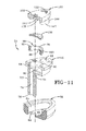
- a tire assembly 10 includes a tire 12, a reversible peristaltic pump assembly 14, and a tire rim 16.
- the tire mounts in a conventional fashion to a pair of rim mounting surfaces 18, 20 located adjacent outer rim flanges 22, 24.
- the outer rim flanges 22, 24 have an outer rim surface 26.
- An annular rim body 28 connects the rim flanges 22, 24 and supports the tire assembly as shown.
- the tire is of conventional construction, having a pair of sidewalls 30, 32 extending from opposite bead areas 34, 36 to a crown or tire tread region 38.
- the tire and rim enclose a tire cavity 40.
- the peristaltic pump assembly 14 includes a pump 41 that is mounted in a passageway 43 located in the sidewall area of the tire, preferably near the bead region.
- the air passageway 43 may be molded into the sidewall of the tire during vulcanization or molded post cure.
- the passageway is preferably annular in shape.
- the pump 41 has a first end or inlet end 42 and a second end or outlet end 44 joined together by a regulator device 54. The first end 42 and the second end 44 are co located, so that the pump body is about 360 degrees in circumference.
- the pump 41 comprises a tube body formed of a resilient, flexible material such as plastic, elastomer or rubber compounds, and is capable of withstanding repeated deformation cycles when the tube is deformed into a flattened condition subject to external force and, upon removal of such force, returns to an original condition generally circular in cross-section.
- the tube is of a diameter sufficient to operatively pass a volume of air sufficient for the purposes described herein and allowing a positioning of the tube in an operable location within the tire assembly as will be described.
- the tube has a circular cross-sectional shape, although other shapes such as elliptical may be utilized.
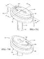
- the regulator device 54 is shown in Figures 4 and Figures 7-15 .
- the regulator device 54 functions to regulate both the inlet and outlet flow of pump 41.
- the regulator device 54 includes an optional outer cover 56 that may be molded into a green tire and then cured or inserted post-cure.
- the optional outer cover 56 has two lateral holes 58, 60 for fluid communication with the inlet tube and outlet tube of the pump 41 as described in more detail, below.
- the cover further comprises an inner cavity 62 formed by sidewalls 64 and bottom wall 66.
- a hole 68 is located in bottom wall.
- a regulator body 70 is received within the inner cavity 62 of the cover 56.
- the regulator body 70 has an outer duct 72 having a first end 74 which is connected to the regulator body and a distal end 76 that is received within the bottom hole 68 of the inner cavity 62.
- the outer duct 72 is sized to have a sufficient length so that the distal end 76 of the duct is in fluid communication with the tire cavity 40.
- the outer duct 72 has a central bore 78 that extends from the first end 74 to the distal end 76.
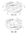
- the first end 74 of the outer duct 72 is connected to a main chamber 80 that is preferably centrally located within the regulator body 70.
- the internal chamber has two opposed holes 82, 84 leading to a left chamber 86 and a right chamber 88 located on either side of the main chamber 80.
- the left chamber 86 has a lateral hole 87 and configured to align with hole 60 in cover.
- the right chamber 88 has a lateral hole 89 and configured to align with hole 58 in cover.
- a ring valve 90 is received within the main chamber 80 and has flanged ends 92 aligned for reception in slots 94 in the sidewalls of the chamber.
- the ring valve 90 is a ring shaped member that is formed of a flexible material such as, but not limited to, rubber, elastomer, plastic or silicone.
- the ring valve 90 has one or more lateral recessed slots 98.
- the outer wall 100 of the ring valve is positioned for mating engagement with holes 82, 84 in main chamber 80.
- a pressure membrane 104 is positioned over the ring valve 90.
- the pressure membrane is a disk shaped member made of a flexible material such as, but not limited to, rubber, elastomer, plastic or silicone.
- the pressure membrane is responsive to the pressure of the outside atmosphere via holes 106, and the tire cavity pressure communicated via duct 72.
- a regulator cap 120 is connected to the regulator body forming internal pathways for managing the airflow within the regulator device.
- This regulator cap 120 can be installed two ways (i.e. reversible) in the regulator body 70 to allow the pumping for a given tire rotating direction.
- the regulator cap has an upper flanged surface 122 having one or more air holes 106 that extend from the upper surface and down through the regulator cap and into a recessed chamber 124.
- the recessed chamber 124 has a flanged portion 128 that surrounds the recessed chamber 124 and is positioned for engagement with the pressure membrane.
- the pressure membrane can engage the flanged portion 128 forming a seal which prevents air flow from port 106 from passing through the regulator device.
- the recessed chamber 124 is connected to a transverse passageway 130 in the regulator cap, that directs airflow to an outlet port 140 formed by a first flanged end 142.
- the outlet port has an exit hole 144 that connects to the right chamber lateral hole 89 of the regulator body which is further connected with cover hole 58 connected to an inlet end 42 of the pump.
- cover hole 58 connected to an inlet end 42 of the pump.
- Figs. 13 and 14 illustrate the air traveling through passageway 130 into port 140 and out the exit hole 144, through the regulator hole 89, through cover hole 89 and into pump inlet tube end 42 as shown in Fig 14 .
- Figure 15 illustrates how air from the peristaltic pump outlet end 44 travels through the regulator device and then is pumped into the tire. Air from the pump outlet end enters the regulator device 54 through the cover hole 60 and then through the aligned regulator hole 87 of regulator 70. Air then enters the regulator cap 120 through a channel 150 located in a second flanged end 154 of the regulator cap.
- the channel 150 has an inlet 152 aligned with the regulator hole 87 and an outlet 156 aligned with hole 82 located in the left chamber of the regulator body.
- the hole 82 is sealed by ring valve, which blocks both holes 82, 84 as shown in Fig 15 to prevent airflow from escaping the tire cavity.
- the regulator device 54 is in fluid communication with the inlet end and the outlet end of the circular air tube 42.
- a footprint 202 is formed against the ground surface 204.
- a compressive force 206 is directed into the tire from the footprint 202 and acts to flatten a segment 110 of the pump 42.
- Flattening of the segment 110 of the pump 41 forces a portion of air located between the flattened segment 110 and the regulator device 54, in the direction shown by arrow 208 towards the regulator device 54.
- the pump tube 41 will be sequentially flattened or squeezed segment by segment 110, 110', 110" etc in a direction 208 which is opposite to the direction of tire rotation 200.
- the sequential flattening of the pump tube 41 segment by segment causes the column of air located between the flattened segments and the regulator device 54 to be pumped into the regulator device 54 and then into the tire cavity.
- the regulator device controls the inflow of air into the pump. If the tire pressure is low, the regulator device will allow the air to enter the regulator device from the pump and then into the tire. Air from the pump tube outlet enters regulator body through cover hole and then through the cap passageway 150. The air pressure generated by the pumping mechanism unseats the ring valve from the regulator hole 82. When the ring valve is unseated by the pump pressure, the air passes through the slots of the ring valve into the chamber and then to the duct 72 which ports the air into tire cavity 40. The regulator may also fill the pump with air at the same time the tire is being pumped.
- the regulator device will block flow from entering the pump inlet.
- the pressure membrane is responsive to the cavity tire pressure and engages the flanged portion 128 of the regulator cap forming a seal which prevents air flow from port 106 from passing through the regulator device.
- the pressure membrane material properties are adjusted to have the desired tire pressure settings.
- the regulator device also functions to prevent flow from the tire cavity into the pump ends via the ring seal which blocks hole 82.
- the peristaltic pump assembly 14 is positioned in the tire sidewall, radially outward of the rim flange surface 26 in the chafer 120. So positioned, the air tube 42 is radially inward from the tire footprint 202 and is thus positioned to be flattened by forces directed from the tire footprint as described above. The segment 110 that is opposite the footprint 202 will flatten from the compressive force 206 from the footprint 202 pressing the tube segment against the rim flange surface 26.
- the positioning of the tube 42 is specifically shown as between a chafer 120 of the tire at the bead region 34 and the rim surface 26, it is not limited to same, and may be located at any region of the tire such as anywhere in the sidewall or tread.
- the diametric sizing of the peristaltic pump air tube 41 is selected to span the circumference of the rim flange surface 26.
- the subject invention provides a peristaltic pump for a self-inflating tire in which a circular air tube 41 flattens segment by segment and closes in the tire footprint 202.
- the regulator device 54 may optionally include a filter (not shown).
- the peristaltic pump assembly 14 pumps air under rotation of the tire in one direction only for a given installation direction of the cap 120. If the cap is installed in the other direction in the body 70, the system pumps while the tire is rotating in the other direction as shown in Figure 3B .
- the peristaltic pump assembly 14 may be used with a secondary tire pressure monitoring system (TPMS) (not shown) of conventional configuration that serves as a system fault detector.
- the TPMS may be used to detect any fault in the self-inflation system of the tire assembly and alert the user of such a condition.
Applications Claiming Priority (1)
| Application Number | Priority Date | Filing Date | Title |
|---|---|---|---|
| US13/221,433 US8573270B2 (en) | 2011-08-30 | 2011-08-30 | Self-inflating tire and pressure regulator |
Publications (2)
| Publication Number | Publication Date |
|---|---|
| EP2565061A1 true EP2565061A1 (fr) | 2013-03-06 |
| EP2565061B1 EP2565061B1 (fr) | 2016-08-03 |
Family
ID=46939526
Family Applications (1)
| Application Number | Title | Priority Date | Filing Date |
|---|---|---|---|
| EP12182073.2A Active EP2565061B1 (fr) | 2011-08-30 | 2012-08-28 | Pneu autogonflant et régulateur de pression pneumatique |
Country Status (5)
| Country | Link |
|---|---|
| US (1) | US8573270B2 (fr) |
| EP (1) | EP2565061B1 (fr) |
| JP (1) | JP6058317B2 (fr) |
| CN (1) | CN102963221B (fr) |
| BR (1) | BR102012021688B1 (fr) |
Cited By (9)
| Publication number | Priority date | Publication date | Assignee | Title |
|---|---|---|---|---|
| EP2746071A2 (fr) * | 2012-12-18 | 2014-06-25 | The Goodyear Tire & Rubber Company | Pneu |
| EP2743102A3 (fr) * | 2012-12-12 | 2014-09-10 | The Goodyear Tire & Rubber Company | Pneu |
| EP2746075A3 (fr) * | 2012-12-21 | 2014-09-10 | The Goodyear Tire & Rubber Company | Système de soupape compacte pour pneu autogonflant |
| EP2746073A3 (fr) * | 2012-12-20 | 2014-09-10 | The Goodyear Tire & Rubber Company | Système de soupape compacte pour pneu autogonflant |
| EP2842772A1 (fr) * | 2013-08-29 | 2015-03-04 | The Goodyear Tire & Rubber Company | Pneu présentant une pompe et un ensemble de soupape |
| EP2853420A1 (fr) * | 2013-09-30 | 2015-04-01 | The Goodyear Tire & Rubber Company | Ensemble valve et pneu |
| EP2886374A3 (fr) * | 2013-12-17 | 2015-07-29 | The Goodyear Tire & Rubber Company | Pneu autogonflable avec régulateur de pression |
| EP2886372A3 (fr) * | 2013-12-17 | 2015-07-29 | The Goodyear Tire & Rubber Company | Pneumatique autogonflant avec soupape de commande d'entrée |
| EP3339060A1 (fr) * | 2016-12-23 | 2018-06-27 | Kumho Tire Co., Inc. | Pneu équipé d'un dispositif de gonflage automatique |
Families Citing this family (43)
| Publication number | Priority date | Publication date | Assignee | Title |
|---|---|---|---|---|
| CZ303718B6 (cs) | 2006-05-23 | 2013-04-03 | Sithold S.R.O. | Komponenta s tvarovou pametí pro upravení tlaku v pneumatice a zpusob její výroby |
| US10124636B2 (en) * | 2008-02-21 | 2018-11-13 | Coda Innovations S.R.O. | Device for adjustment of pressure in tires |
| US8857484B2 (en) * | 2011-08-30 | 2014-10-14 | The Goodyear Tire & Rubber Company | Self-inflating tire |
| US9290057B2 (en) | 2011-10-31 | 2016-03-22 | Innovative Technologies, Llc | All season safety tire |
| US9278584B2 (en) | 2011-10-31 | 2016-03-08 | Innovative Technologies, Llc | All-weather tire |
| US8820369B2 (en) * | 2011-11-09 | 2014-09-02 | The Goodyear Tire & Rubber Company | Self-inflating tire |
| CZ2011757A3 (cs) | 2011-11-22 | 2013-05-29 | Sithold S.R.O | Zarízení pro udrzování a zmenu tlaku v pneumatice |
| US8991456B2 (en) * | 2012-06-28 | 2015-03-31 | The Goodyear Tire & Rubber Company | Reversible air maintenance tire and pump assembly |
| US8960249B2 (en) * | 2012-10-15 | 2015-02-24 | The Goodyear Tire & Rubber Company | Self-inflating tire |
| US20140130895A1 (en) * | 2012-11-15 | 2014-05-15 | The Goodyear Tire & Rubber Company | Connector system and air maintenance tire assembly |
| US9242518B2 (en) | 2012-12-20 | 2016-01-26 | The Goodyear Tire & Rubber Company | Compact valve system for self-inflating tire |
| US9421832B2 (en) * | 2013-02-04 | 2016-08-23 | The Goodyear Tire & Rubber Company | Air maintenance tire |
| US11453258B2 (en) | 2013-03-12 | 2022-09-27 | Aperia Technologies, Inc. | System for tire inflation |
| US9327560B2 (en) * | 2013-08-29 | 2016-05-03 | The Goodyear Tire & Rubber Company | Compact valve system for self-inflating tire |
| US9327561B2 (en) * | 2013-08-29 | 2016-05-03 | The Goodyear Tire & Rubber Company | Compact valve system for self-inflating tire |
| US20150059953A1 (en) * | 2013-08-30 | 2015-03-05 | The Goodyear Tire & Rubber Company | Method of assembly of air maintenance tire system |
| US9259981B2 (en) * | 2013-11-05 | 2016-02-16 | The Goodyear Tire & Rubber Company | Valve stem-based pressure regulator system for an air maintenance tire and method |
| US9272586B2 (en) * | 2013-11-05 | 2016-03-01 | The Goodyear Tire & Rubber Company | Valve stem-based air maintenance tire and method |
| CN104648060A (zh) * | 2013-11-26 | 2015-05-27 | 杜永财 | 轮胎自动充气环 |
| US9365084B2 (en) * | 2013-12-11 | 2016-06-14 | The Goodyear Tire & Rubber Company | Self-inflating tire and pressure regulator |
| US9539869B2 (en) * | 2013-12-11 | 2017-01-10 | The Goodyear Tire & Rubber Company | Self-inflating tire and pressure regulator |
| US9216620B2 (en) * | 2013-12-16 | 2015-12-22 | The Goodyear Tire & Rubber Company | Peristaltic air pumping tube and tire assembly and method |
| US9205712B2 (en) * | 2013-12-16 | 2015-12-08 | The Goodyear Tire & Rubber Company | Snap-in inlet and connection method for air maintenance tire |
| US20150165838A1 (en) | 2013-12-16 | 2015-06-18 | The Goodyear Tire & Rubber Company | Filter assembly for air maintenance tire |
| US9701166B2 (en) * | 2013-12-17 | 2017-07-11 | The Goodyear Tire & Rubber Company | Bi-directional self-inflating tire with pressure regulator |
| US9662944B2 (en) | 2013-12-23 | 2017-05-30 | The Goodyear Tire & Rubber Company | Self inflating tire with pressure regulator |
| US9387737B2 (en) | 2014-08-07 | 2016-07-12 | The Goodyear Tire & Rubber Company | Passage tube for air maintenance tire |
| US9744816B2 (en) | 2014-08-12 | 2017-08-29 | The Goodyear Tire & Rubber Company | Air maintenance tire |
| US9783015B2 (en) | 2014-08-12 | 2017-10-10 | The Goodyear Tire & Rubber Company | Control regulator and pumping system for an air maintenance tire |
| US20160052352A1 (en) | 2014-08-21 | 2016-02-25 | The Goodyear Tire & Rubber Company | Method of adhesion of rigid components to a tire |
| US9533534B2 (en) * | 2014-10-22 | 2017-01-03 | The Goodyear Tire & Rubber Company | Air maintenance tire and valve assembly and method |
| US9418492B2 (en) | 2014-11-06 | 2016-08-16 | The Goodyear Tire & Rubber Company | Mobile phone enabled data processing system |
| US9604511B2 (en) * | 2015-08-11 | 2017-03-28 | The Goodyear Tire & Rubber Company | Air maintenance pumping assembly and tire |
| US9796223B2 (en) * | 2015-11-19 | 2017-10-24 | The Goodyear Tire & Rubber Company | Valve stem-based air maintenance tire and method |
| US9796224B2 (en) * | 2015-11-19 | 2017-10-24 | The Goodyear Tire & Rubber Company | Valve stem-based air maintenance tire and method |
| JP2018083618A (ja) * | 2016-11-23 | 2018-05-31 | ザ・グッドイヤー・タイヤ・アンド・ラバー・カンパニー | エアメンテナンスタイヤの取付け部材 |
| US10315470B2 (en) * | 2016-12-06 | 2019-06-11 | The Goodyear Tire & Rubber Company | Air maintenance tire and valve assembly and method |
| US11285764B2 (en) | 2016-12-22 | 2022-03-29 | The Goodyear Tire & Rubber Company | Control valve for an air maintenance tire |
| US10807422B2 (en) | 2016-12-22 | 2020-10-20 | The Goodyear Tire & Rubber Company | Inlet control valve for an air maintenance tire |
| KR101870083B1 (ko) * | 2017-05-25 | 2018-06-22 | 주식회사 코아칩스 | 타이어 공기압 유지 장치 |
| KR101999109B1 (ko) | 2017-10-24 | 2019-07-11 | 금호타이어 주식회사 | 공기압 유지 타이어 |
| KR102463428B1 (ko) * | 2017-12-07 | 2022-11-03 | 현대자동차주식회사 | 차량용 먼지 센서 |
| WO2020112686A1 (fr) | 2018-11-27 | 2020-06-04 | Aperia Technologies, Inc. | Système de gonflage intégré dans le moyeu |
Citations (4)
| Publication number | Priority date | Publication date | Assignee | Title |
|---|---|---|---|---|
| EP1604842A1 (fr) * | 2004-06-11 | 2005-12-14 | Ford Global Technologies, LLC | Dispositif de pressuration automatique pour des pneumatiques |
| DE102005031099A1 (de) * | 2005-06-27 | 2007-01-04 | Siemens Ag | Luftbefüllungseinrichtung für Fahrzeugreifen |
| WO2007134556A1 (fr) * | 2006-05-23 | 2007-11-29 | Coda Development, S.R.O. | Chambre de pompe péristaltique pour le réglage de pression de pneu |
| US20110120611A1 (en) * | 2009-11-23 | 2011-05-26 | Hansen Anthony D A | Automatic inflator and method for maintaining a tire pressure |
Family Cites Families (11)
| Publication number | Priority date | Publication date | Assignee | Title |
|---|---|---|---|---|
| US2095489A (en) | 1934-09-13 | 1937-10-12 | Cotton George Albert | Pneumatic tire |
| DE2632622A1 (de) | 1975-07-25 | 1977-02-10 | Dunlop Ltd | Luftreifen |
| JPS5823706U (ja) * | 1981-08-10 | 1983-02-15 | トヨタ自動車株式会社 | タイヤ空気の自動補給装置 |
| JPS6253204A (ja) * | 1985-08-31 | 1987-03-07 | Teruhiko Yamamoto | タイヤの空気圧調節装置 |
| FR2618102B1 (fr) * | 1987-07-15 | 1990-02-16 | Michelin & Cie | Gonflage d'un pneumatique en rotation |
| US20040112495A1 (en) | 2002-12-09 | 2004-06-17 | Curtis Arlen Weise | Self inflating tire |
| DE10335244A1 (de) * | 2003-08-01 | 2005-03-10 | Bayerische Motoren Werke Ag | Vorrichtung zur Luftbefüllung eines rotierenden Luftreifens |
| US8113254B2 (en) * | 2009-12-21 | 2012-02-14 | The Goodyear Tire & Rubber Company | Self-inflating tire |
| US8042586B2 (en) * | 2009-12-21 | 2011-10-25 | The Goodyear Tire & Rubber Company | Self-inflating tire assembly |
| US8235081B2 (en) * | 2010-11-22 | 2012-08-07 | The Goodyear Tire & Rubber Company | In-line pumping assembly for self-inflating tire |
| US8857484B2 (en) * | 2011-08-30 | 2014-10-14 | The Goodyear Tire & Rubber Company | Self-inflating tire |
-
2011
- 2011-08-30 US US13/221,433 patent/US8573270B2/en active Active
-
2012
- 2012-08-23 JP JP2012184043A patent/JP6058317B2/ja active Active
- 2012-08-28 EP EP12182073.2A patent/EP2565061B1/fr active Active
- 2012-08-28 BR BR102012021688-4A patent/BR102012021688B1/pt active IP Right Grant
- 2012-08-30 CN CN201210314658.0A patent/CN102963221B/zh active Active
Patent Citations (4)
| Publication number | Priority date | Publication date | Assignee | Title |
|---|---|---|---|---|
| EP1604842A1 (fr) * | 2004-06-11 | 2005-12-14 | Ford Global Technologies, LLC | Dispositif de pressuration automatique pour des pneumatiques |
| DE102005031099A1 (de) * | 2005-06-27 | 2007-01-04 | Siemens Ag | Luftbefüllungseinrichtung für Fahrzeugreifen |
| WO2007134556A1 (fr) * | 2006-05-23 | 2007-11-29 | Coda Development, S.R.O. | Chambre de pompe péristaltique pour le réglage de pression de pneu |
| US20110120611A1 (en) * | 2009-11-23 | 2011-05-26 | Hansen Anthony D A | Automatic inflator and method for maintaining a tire pressure |
Cited By (16)
| Publication number | Priority date | Publication date | Assignee | Title |
|---|---|---|---|---|
| EP2743102A3 (fr) * | 2012-12-12 | 2014-09-10 | The Goodyear Tire & Rubber Company | Pneu |
| US9061556B2 (en) | 2012-12-12 | 2015-06-23 | The Goodyear Tire & Rubber Company | Air maintenance pneumatic tire |
| US9050858B2 (en) | 2012-12-18 | 2015-06-09 | The Goodyear Tire & Rubber Company | Peristaltic pump air maintenance tire |
| EP2746071A3 (fr) * | 2012-12-18 | 2014-09-10 | The Goodyear Tire & Rubber Company | Pneu |
| EP2746071A2 (fr) * | 2012-12-18 | 2014-06-25 | The Goodyear Tire & Rubber Company | Pneu |
| EP2746073A3 (fr) * | 2012-12-20 | 2014-09-10 | The Goodyear Tire & Rubber Company | Système de soupape compacte pour pneu autogonflant |
| EP2746075A3 (fr) * | 2012-12-21 | 2014-09-10 | The Goodyear Tire & Rubber Company | Système de soupape compacte pour pneu autogonflant |
| EP2842772A1 (fr) * | 2013-08-29 | 2015-03-04 | The Goodyear Tire & Rubber Company | Pneu présentant une pompe et un ensemble de soupape |
| US9381780B2 (en) | 2013-08-29 | 2016-07-05 | The Goodyear Tire & Rubber Company | Compact valve system for self-inflating tire |
| EP2853420A1 (fr) * | 2013-09-30 | 2015-04-01 | The Goodyear Tire & Rubber Company | Ensemble valve et pneu |
| EP2886374A3 (fr) * | 2013-12-17 | 2015-07-29 | The Goodyear Tire & Rubber Company | Pneu autogonflable avec régulateur de pression |
| EP2886372A3 (fr) * | 2013-12-17 | 2015-07-29 | The Goodyear Tire & Rubber Company | Pneumatique autogonflant avec soupape de commande d'entrée |
| US9233582B2 (en) | 2013-12-17 | 2016-01-12 | The Goodyear Tire & Rubber Company | Self-inflating tire with inlet control valve |
| US9758000B2 (en) | 2013-12-17 | 2017-09-12 | The Goodyear Tire & Rubber Company | Self-inflating tire with pressure regulator |
| EP3339060A1 (fr) * | 2016-12-23 | 2018-06-27 | Kumho Tire Co., Inc. | Pneu équipé d'un dispositif de gonflage automatique |
| US10442259B2 (en) | 2016-12-23 | 2019-10-15 | Kumho Tire Co., Inc. | Tire with self-inflation device |
Also Published As
| Publication number | Publication date |
|---|---|
| US20130048177A1 (en) | 2013-02-28 |
| JP6058317B2 (ja) | 2017-01-11 |
| JP2013049410A (ja) | 2013-03-14 |
| CN102963221A (zh) | 2013-03-13 |
| BR102012021688A2 (pt) | 2013-07-30 |
| EP2565061B1 (fr) | 2016-08-03 |
| US8573270B2 (en) | 2013-11-05 |
| BR102012021688B1 (pt) | 2020-12-08 |
| CN102963221B (zh) | 2015-06-24 |
Similar Documents
| Publication | Publication Date | Title |
|---|---|---|
| EP2565061B1 (fr) | Pneu autogonflant et régulateur de pression pneumatique | |
| EP2565060B1 (fr) | Pneu autogonflant | |
| EP2565059B1 (fr) | Pneu | |
| EP2746073B1 (fr) | Système de soupape compacte pour pneu autogonflant | |
| EP2842772B1 (fr) | Pneu présentant une pompe et un ensemble de soupape | |
| EP2343200B1 (fr) | Pneu autogonflant | |
| EP2746072B1 (fr) | Système de soupape compacte pour pneu autogonflant | |
| EP2886374B1 (fr) | Pneu autogonflable avec régulateur de pression | |
| EP2746075A2 (fr) | Système de soupape compacte pour pneu autogonflant | |
| EP2883719B1 (fr) | Pneu autogonflant et régulateur de pression pneumatique | |
| EP2883717B1 (fr) | Pneu autogonflant et régulateur de pression pneumatique | |
| EP2886373B1 (fr) | Pneumatique autogonflant bidirectionnel avec régulateur de pression | |
| EP2842774B1 (fr) | Pneu présentant une pompe et un ensemble de soupape | |
| EP2886372B1 (fr) | Pneumatique autogonflant avec soupape de commande d'entrée | |
| EP2886375A2 (fr) | Pneu auto-gonflable avec régulateur de pression | |
| EP2883718B1 (fr) | Pneumatique autogonflant avec pompe hybride |
Legal Events
| Date | Code | Title | Description |
|---|---|---|---|
| PUAI | Public reference made under article 153(3) epc to a published international application that has entered the european phase |
Free format text: ORIGINAL CODE: 0009012 |
|
| AK | Designated contracting states |
Kind code of ref document: A1 Designated state(s): AL AT BE BG CH CY CZ DE DK EE ES FI FR GB GR HR HU IE IS IT LI LT LU LV MC MK MT NL NO PL PT RO RS SE SI SK SM TR |
|
| AX | Request for extension of the european patent |
Extension state: BA ME |
|
| 17P | Request for examination filed |
Effective date: 20130906 |
|
| RBV | Designated contracting states (corrected) |
Designated state(s): AL AT BE BG CH CY CZ DE DK EE ES FI FR GB GR HR HU IE IS IT LI LT LU LV MC MK MT NL NO PL PT RO RS SE SI SK SM TR |
|
| 17Q | First examination report despatched |
Effective date: 20150505 |
|
| GRAP | Despatch of communication of intention to grant a patent |
Free format text: ORIGINAL CODE: EPIDOSNIGR1 |
|
| INTG | Intention to grant announced |
Effective date: 20160309 |
|
| GRAS | Grant fee paid |
Free format text: ORIGINAL CODE: EPIDOSNIGR3 |
|
| GRAA | (expected) grant |
Free format text: ORIGINAL CODE: 0009210 |
|
| AK | Designated contracting states |
Kind code of ref document: B1 Designated state(s): AL AT BE BG CH CY CZ DE DK EE ES FI FR GB GR HR HU IE IS IT LI LT LU LV MC MK MT NL NO PL PT RO RS SE SI SK SM TR |
|
| REG | Reference to a national code |
Ref country code: GB Ref legal event code: FG4D |
|
| REG | Reference to a national code |
Ref country code: CH Ref legal event code: EP Ref country code: AT Ref legal event code: REF Ref document number: 817087 Country of ref document: AT Kind code of ref document: T Effective date: 20160815 |
|
| REG | Reference to a national code |
Ref country code: FR Ref legal event code: PLFP Year of fee payment: 5 |
|
| REG | Reference to a national code |
Ref country code: IE Ref legal event code: FG4D |
|
| REG | Reference to a national code |
Ref country code: DE Ref legal event code: R096 Ref document number: 602012021178 Country of ref document: DE |
|
| REG | Reference to a national code |
Ref country code: NL Ref legal event code: MP Effective date: 20160803 |
|
| REG | Reference to a national code |
Ref country code: LT Ref legal event code: MG4D |
|
| REG | Reference to a national code |
Ref country code: AT Ref legal event code: MK05 Ref document number: 817087 Country of ref document: AT Kind code of ref document: T Effective date: 20160803 |
|
| PG25 | Lapsed in a contracting state [announced via postgrant information from national office to epo] |
Ref country code: NO Free format text: LAPSE BECAUSE OF FAILURE TO SUBMIT A TRANSLATION OF THE DESCRIPTION OR TO PAY THE FEE WITHIN THE PRESCRIBED TIME-LIMIT Effective date: 20161103 Ref country code: RS Free format text: LAPSE BECAUSE OF FAILURE TO SUBMIT A TRANSLATION OF THE DESCRIPTION OR TO PAY THE FEE WITHIN THE PRESCRIBED TIME-LIMIT Effective date: 20160803 Ref country code: LT Free format text: LAPSE BECAUSE OF FAILURE TO SUBMIT A TRANSLATION OF THE DESCRIPTION OR TO PAY THE FEE WITHIN THE PRESCRIBED TIME-LIMIT Effective date: 20160803 Ref country code: HR Free format text: LAPSE BECAUSE OF FAILURE TO SUBMIT A TRANSLATION OF THE DESCRIPTION OR TO PAY THE FEE WITHIN THE PRESCRIBED TIME-LIMIT Effective date: 20160803 Ref country code: NL Free format text: LAPSE BECAUSE OF FAILURE TO SUBMIT A TRANSLATION OF THE DESCRIPTION OR TO PAY THE FEE WITHIN THE PRESCRIBED TIME-LIMIT Effective date: 20160803 Ref country code: IS Free format text: LAPSE BECAUSE OF FAILURE TO SUBMIT A TRANSLATION OF THE DESCRIPTION OR TO PAY THE FEE WITHIN THE PRESCRIBED TIME-LIMIT Effective date: 20161203 Ref country code: FI Free format text: LAPSE BECAUSE OF FAILURE TO SUBMIT A TRANSLATION OF THE DESCRIPTION OR TO PAY THE FEE WITHIN THE PRESCRIBED TIME-LIMIT Effective date: 20160803 |
|
| PG25 | Lapsed in a contracting state [announced via postgrant information from national office to epo] |
Ref country code: SE Free format text: LAPSE BECAUSE OF FAILURE TO SUBMIT A TRANSLATION OF THE DESCRIPTION OR TO PAY THE FEE WITHIN THE PRESCRIBED TIME-LIMIT Effective date: 20160803 Ref country code: LV Free format text: LAPSE BECAUSE OF FAILURE TO SUBMIT A TRANSLATION OF THE DESCRIPTION OR TO PAY THE FEE WITHIN THE PRESCRIBED TIME-LIMIT Effective date: 20160803 Ref country code: ES Free format text: LAPSE BECAUSE OF FAILURE TO SUBMIT A TRANSLATION OF THE DESCRIPTION OR TO PAY THE FEE WITHIN THE PRESCRIBED TIME-LIMIT Effective date: 20160803 Ref country code: PT Free format text: LAPSE BECAUSE OF FAILURE TO SUBMIT A TRANSLATION OF THE DESCRIPTION OR TO PAY THE FEE WITHIN THE PRESCRIBED TIME-LIMIT Effective date: 20161205 Ref country code: PL Free format text: LAPSE BECAUSE OF FAILURE TO SUBMIT A TRANSLATION OF THE DESCRIPTION OR TO PAY THE FEE WITHIN THE PRESCRIBED TIME-LIMIT Effective date: 20160803 Ref country code: BE Free format text: LAPSE BECAUSE OF NON-PAYMENT OF DUE FEES Effective date: 20160831 Ref country code: AT Free format text: LAPSE BECAUSE OF FAILURE TO SUBMIT A TRANSLATION OF THE DESCRIPTION OR TO PAY THE FEE WITHIN THE PRESCRIBED TIME-LIMIT Effective date: 20160803 Ref country code: GR Free format text: LAPSE BECAUSE OF FAILURE TO SUBMIT A TRANSLATION OF THE DESCRIPTION OR TO PAY THE FEE WITHIN THE PRESCRIBED TIME-LIMIT Effective date: 20161104 |
|
| REG | Reference to a national code |
Ref country code: CH Ref legal event code: PL |
|
| PG25 | Lapsed in a contracting state [announced via postgrant information from national office to epo] |
Ref country code: EE Free format text: LAPSE BECAUSE OF FAILURE TO SUBMIT A TRANSLATION OF THE DESCRIPTION OR TO PAY THE FEE WITHIN THE PRESCRIBED TIME-LIMIT Effective date: 20160803 Ref country code: RO Free format text: LAPSE BECAUSE OF FAILURE TO SUBMIT A TRANSLATION OF THE DESCRIPTION OR TO PAY THE FEE WITHIN THE PRESCRIBED TIME-LIMIT Effective date: 20160803 Ref country code: CH Free format text: LAPSE BECAUSE OF NON-PAYMENT OF DUE FEES Effective date: 20160831 Ref country code: LI Free format text: LAPSE BECAUSE OF NON-PAYMENT OF DUE FEES Effective date: 20160831 |
|
| REG | Reference to a national code |
Ref country code: DE Ref legal event code: R097 Ref document number: 602012021178 Country of ref document: DE |
|
| PG25 | Lapsed in a contracting state [announced via postgrant information from national office to epo] |
Ref country code: SK Free format text: LAPSE BECAUSE OF FAILURE TO SUBMIT A TRANSLATION OF THE DESCRIPTION OR TO PAY THE FEE WITHIN THE PRESCRIBED TIME-LIMIT Effective date: 20160803 Ref country code: SM Free format text: LAPSE BECAUSE OF FAILURE TO SUBMIT A TRANSLATION OF THE DESCRIPTION OR TO PAY THE FEE WITHIN THE PRESCRIBED TIME-LIMIT Effective date: 20160803 Ref country code: CZ Free format text: LAPSE BECAUSE OF FAILURE TO SUBMIT A TRANSLATION OF THE DESCRIPTION OR TO PAY THE FEE WITHIN THE PRESCRIBED TIME-LIMIT Effective date: 20160803 Ref country code: BG Free format text: LAPSE BECAUSE OF FAILURE TO SUBMIT A TRANSLATION OF THE DESCRIPTION OR TO PAY THE FEE WITHIN THE PRESCRIBED TIME-LIMIT Effective date: 20161103 Ref country code: BE Free format text: LAPSE BECAUSE OF FAILURE TO SUBMIT A TRANSLATION OF THE DESCRIPTION OR TO PAY THE FEE WITHIN THE PRESCRIBED TIME-LIMIT Effective date: 20160803 Ref country code: DK Free format text: LAPSE BECAUSE OF FAILURE TO SUBMIT A TRANSLATION OF THE DESCRIPTION OR TO PAY THE FEE WITHIN THE PRESCRIBED TIME-LIMIT Effective date: 20160803 |
|
| REG | Reference to a national code |
Ref country code: IE Ref legal event code: MM4A |
|
| PLBE | No opposition filed within time limit |
Free format text: ORIGINAL CODE: 0009261 |
|
| STAA | Information on the status of an ep patent application or granted ep patent |
Free format text: STATUS: NO OPPOSITION FILED WITHIN TIME LIMIT |
|
| PG25 | Lapsed in a contracting state [announced via postgrant information from national office to epo] |
Ref country code: MC Free format text: LAPSE BECAUSE OF FAILURE TO SUBMIT A TRANSLATION OF THE DESCRIPTION OR TO PAY THE FEE WITHIN THE PRESCRIBED TIME-LIMIT Effective date: 20160803 |
|
| 26N | No opposition filed |
Effective date: 20170504 |
|
| REG | Reference to a national code |
Ref country code: FR Ref legal event code: PLFP Year of fee payment: 6 |
|
| GBPC | Gb: european patent ceased through non-payment of renewal fee |
Effective date: 20161103 |
|
| PG25 | Lapsed in a contracting state [announced via postgrant information from national office to epo] |
Ref country code: IE Free format text: LAPSE BECAUSE OF NON-PAYMENT OF DUE FEES Effective date: 20160828 |
|
| PG25 | Lapsed in a contracting state [announced via postgrant information from national office to epo] |
Ref country code: SI Free format text: LAPSE BECAUSE OF FAILURE TO SUBMIT A TRANSLATION OF THE DESCRIPTION OR TO PAY THE FEE WITHIN THE PRESCRIBED TIME-LIMIT Effective date: 20160803 Ref country code: LU Free format text: LAPSE BECAUSE OF NON-PAYMENT OF DUE FEES Effective date: 20160828 |
|
| PG25 | Lapsed in a contracting state [announced via postgrant information from national office to epo] |
Ref country code: GB Free format text: LAPSE BECAUSE OF NON-PAYMENT OF DUE FEES Effective date: 20161103 |
|
| PG25 | Lapsed in a contracting state [announced via postgrant information from national office to epo] |
Ref country code: CY Free format text: LAPSE BECAUSE OF FAILURE TO SUBMIT A TRANSLATION OF THE DESCRIPTION OR TO PAY THE FEE WITHIN THE PRESCRIBED TIME-LIMIT Effective date: 20160803 Ref country code: HU Free format text: LAPSE BECAUSE OF FAILURE TO SUBMIT A TRANSLATION OF THE DESCRIPTION OR TO PAY THE FEE WITHIN THE PRESCRIBED TIME-LIMIT; INVALID AB INITIO Effective date: 20120828 |
|
| PG25 | Lapsed in a contracting state [announced via postgrant information from national office to epo] |
Ref country code: TR Free format text: LAPSE BECAUSE OF FAILURE TO SUBMIT A TRANSLATION OF THE DESCRIPTION OR TO PAY THE FEE WITHIN THE PRESCRIBED TIME-LIMIT Effective date: 20160803 Ref country code: MK Free format text: LAPSE BECAUSE OF FAILURE TO SUBMIT A TRANSLATION OF THE DESCRIPTION OR TO PAY THE FEE WITHIN THE PRESCRIBED TIME-LIMIT Effective date: 20160803 Ref country code: MT Free format text: LAPSE BECAUSE OF NON-PAYMENT OF DUE FEES Effective date: 20160831 |
|
| REG | Reference to a national code |
Ref country code: FR Ref legal event code: PLFP Year of fee payment: 7 |
|
| PG25 | Lapsed in a contracting state [announced via postgrant information from national office to epo] |
Ref country code: AL Free format text: LAPSE BECAUSE OF FAILURE TO SUBMIT A TRANSLATION OF THE DESCRIPTION OR TO PAY THE FEE WITHIN THE PRESCRIBED TIME-LIMIT Effective date: 20160803 |
|
| PGFP | Annual fee paid to national office [announced via postgrant information from national office to epo] |
Ref country code: IT Payment date: 20230711 Year of fee payment: 12 |
|
| PGFP | Annual fee paid to national office [announced via postgrant information from national office to epo] |
Ref country code: FR Payment date: 20230703 Year of fee payment: 12 Ref country code: DE Payment date: 20230703 Year of fee payment: 12 |