EP2564959A1 - Stellschraube für ein Spannfutter und damit ausgerüstetes Spannfutter für ein Werkzeug - Google Patents
Stellschraube für ein Spannfutter und damit ausgerüstetes Spannfutter für ein Werkzeug Download PDFInfo
- Publication number
- EP2564959A1 EP2564959A1 EP11166950A EP11166950A EP2564959A1 EP 2564959 A1 EP2564959 A1 EP 2564959A1 EP 11166950 A EP11166950 A EP 11166950A EP 11166950 A EP11166950 A EP 11166950A EP 2564959 A1 EP2564959 A1 EP 2564959A1
- Authority
- EP
- European Patent Office
- Prior art keywords
- chuck
- tool
- sleeve
- tubular element
- adjusting screw
- Prior art date
- Legal status (The legal status is an assumption and is not a legal conclusion. Google has not performed a legal analysis and makes no representation as to the accuracy of the status listed.)
- Withdrawn
Links
- 230000008878 coupling Effects 0.000 claims abstract description 10
- 238000010168 coupling process Methods 0.000 claims abstract description 10
- 238000005859 coupling reaction Methods 0.000 claims abstract description 10
- 239000000314 lubricant Substances 0.000 claims description 13
- 238000003780 insertion Methods 0.000 claims description 9
- 230000037431 insertion Effects 0.000 claims description 9
- 238000001816 cooling Methods 0.000 claims description 8
- 230000001050 lubricating effect Effects 0.000 claims description 7
- 239000000463 material Substances 0.000 claims description 7
- 239000002184 metal Substances 0.000 claims description 6
- 230000035515 penetration Effects 0.000 claims 1
- 239000002173 cutting fluid Substances 0.000 abstract 2
- 241000209035 Ilex Species 0.000 description 18
- 239000002826 coolant Substances 0.000 description 7
- 238000013461 design Methods 0.000 description 5
- 230000015572 biosynthetic process Effects 0.000 description 3
- 238000010276 construction Methods 0.000 description 3
- 238000006073 displacement reaction Methods 0.000 description 3
- 230000005540 biological transmission Effects 0.000 description 2
- 239000000919 ceramic Substances 0.000 description 2
- 239000011248 coating agent Substances 0.000 description 2
- 238000000576 coating method Methods 0.000 description 2
- 238000011161 development Methods 0.000 description 2
- 230000018109 developmental process Effects 0.000 description 2
- 230000003993 interaction Effects 0.000 description 2
- 238000012423 maintenance Methods 0.000 description 2
- 229920000642 polymer Polymers 0.000 description 2
- 230000003247 decreasing effect Effects 0.000 description 1
- 230000001419 dependent effect Effects 0.000 description 1
- 230000006698 induction Effects 0.000 description 1
- 238000009434 installation Methods 0.000 description 1
- 238000000034 method Methods 0.000 description 1
- 230000008569 process Effects 0.000 description 1
- 238000007789 sealing Methods 0.000 description 1
- 238000000926 separation method Methods 0.000 description 1
- 238000012546 transfer Methods 0.000 description 1
- 230000007704 transition Effects 0.000 description 1
- 230000032258 transport Effects 0.000 description 1
Images

Classifications
-
- B—PERFORMING OPERATIONS; TRANSPORTING
- B23—MACHINE TOOLS; METAL-WORKING NOT OTHERWISE PROVIDED FOR
- B23Q—DETAILS, COMPONENTS, OR ACCESSORIES FOR MACHINE TOOLS, e.g. ARRANGEMENTS FOR COPYING OR CONTROLLING; MACHINE TOOLS IN GENERAL CHARACTERISED BY THE CONSTRUCTION OF PARTICULAR DETAILS OR COMPONENTS; COMBINATIONS OR ASSOCIATIONS OF METAL-WORKING MACHINES, NOT DIRECTED TO A PARTICULAR RESULT
- B23Q11/00—Accessories fitted to machine tools for keeping tools or parts of the machine in good working condition or for cooling work; Safety devices specially combined with or arranged in, or specially adapted for use in connection with, machine tools
- B23Q11/10—Arrangements for cooling or lubricating tools or work
- B23Q11/1015—Arrangements for cooling or lubricating tools or work by supplying a cutting liquid through the spindle
- B23Q11/1023—Tool holders, or tools in general specially adapted for receiving the cutting liquid from the spindle
-
- B—PERFORMING OPERATIONS; TRANSPORTING
- B23—MACHINE TOOLS; METAL-WORKING NOT OTHERWISE PROVIDED FOR
- B23B—TURNING; BORING
- B23B31/00—Chucks; Expansion mandrels; Adaptations thereof for remote control
- B23B31/02—Chucks
- B23B31/028—Chucks the axial positioning of the tool being adjustable
-
- B—PERFORMING OPERATIONS; TRANSPORTING
- B23—MACHINE TOOLS; METAL-WORKING NOT OTHERWISE PROVIDED FOR
- B23B—TURNING; BORING
- B23B31/00—Chucks; Expansion mandrels; Adaptations thereof for remote control
- B23B31/02—Chucks
- B23B31/24—Chucks characterised by features relating primarily to remote control of the gripping means
- B23B31/30—Chucks characterised by features relating primarily to remote control of the gripping means using fluid-pressure means in the chuck
- B23B31/305—Chucks characterised by features relating primarily to remote control of the gripping means using fluid-pressure means in the chuck the gripping means is a deformable sleeve
-
- B—PERFORMING OPERATIONS; TRANSPORTING
- B23—MACHINE TOOLS; METAL-WORKING NOT OTHERWISE PROVIDED FOR
- B23Q—DETAILS, COMPONENTS, OR ACCESSORIES FOR MACHINE TOOLS, e.g. ARRANGEMENTS FOR COPYING OR CONTROLLING; MACHINE TOOLS IN GENERAL CHARACTERISED BY THE CONSTRUCTION OF PARTICULAR DETAILS OR COMPONENTS; COMBINATIONS OR ASSOCIATIONS OF METAL-WORKING MACHINES, NOT DIRECTED TO A PARTICULAR RESULT
- B23Q1/00—Members which are comprised in the general build-up of a form of machine, particularly relatively large fixed members
- B23Q1/0009—Energy-transferring means or control lines for movable machine parts; Control panels or boxes; Control parts
- B23Q1/0018—Energy-transferring means or control lines for movable machine parts; Control panels or boxes; Control parts comprising hydraulic means
-
- B—PERFORMING OPERATIONS; TRANSPORTING
- B23—MACHINE TOOLS; METAL-WORKING NOT OTHERWISE PROVIDED FOR
- B23Q—DETAILS, COMPONENTS, OR ACCESSORIES FOR MACHINE TOOLS, e.g. ARRANGEMENTS FOR COPYING OR CONTROLLING; MACHINE TOOLS IN GENERAL CHARACTERISED BY THE CONSTRUCTION OF PARTICULAR DETAILS OR COMPONENTS; COMBINATIONS OR ASSOCIATIONS OF METAL-WORKING MACHINES, NOT DIRECTED TO A PARTICULAR RESULT
- B23Q11/00—Accessories fitted to machine tools for keeping tools or parts of the machine in good working condition or for cooling work; Safety devices specially combined with or arranged in, or specially adapted for use in connection with, machine tools
Definitions
- the invention relates generally to a chuck for a tool, and more particularly to a set screw for use in such a chuck according to the preamble of claim 1.
- the EP 1 127 656 B1 describes a chuck according to claim 7 and an adjusting screw according to the preamble of claim 1, ie a tool holder for a machine tool, in which a connecting tube is slidably mounted and depending on the length of a tool to be used longitudinally adjustable in a lubricant receiving tube.
- such a chuck is known from TA 30 8243 01 of the company bielomatik LEUZE GmbH + Co, D-72637 Neuffen.
- This can also be used as a chuck for tools which must be held at different depths in the chuck and held for this purpose by means of a shrink connection or by means of a hydraulic expansion chuck.
- the pipe nozzle or the pipe element is guided longitudinally displaceable in the adjusting screw and the adjusting screw is also longitudinally adjustable by means of a turning key in the chuck, so that the screw on contact with the tensioned chuck tool can be rotated.
- the adjusting screw is also used for manually adjusting the insertion depth of the tool, whereby the pipe nozzle and the sleeve have to be temporarily removed for turning the adjusting screw. This temporary dismantling is also required if the insertion depth adjustment by means of a lance is automated (see eg Induction shrinking device GISS 3000 in the catalog of Fa.
- the object of the invention is to propose a chuck, which simplifies or reduces the work steps during the first and repeated setting of the insertion depth of a tool. Another object is to provide an adjusting screw, with a more economical operation of a generic chuck is possible.
- the chuck according to the invention has a tubular element, which is longitudinally displaceable in the sleeve, can be actuated at an end located in the sleeve by an adjusting tool and is positively and / or non-positively connected with the adjusting screw.
- This makes it possible to turn the adjusting screw, in particular in the formation of a suitable engagement on the tubular element directly by means of an adjusting tool, which cooperates through the sleeve with the intervention, with the interposition of the tubular element, without having to dismantle the tubular element and the sleeve.
- the screw can be rotated after an automated setting of the insertion depth of a tool which is made in a special device by means of a lance, without disassembly of the sleeve and pipe element to the tool. It is also possible with a manual adjustment of the insertion depth of the tool, in which instead of the lance the screw as a stop for the Einstecktiefenbetician the tool serves to turn the adjusting screw without disassembly of the sleeve and the tubular element with the adjusting tool in the desired position.
- the user also has these advantages when the tool has to be readjusted as a result of the wear, that is, it has to be clamped with a different insertion depth.
- the invention provides for the pipe element to be glued to the adjusting screw or screwed against rotation or connected by a corresponding contour rotatably.
- tube elements of different lengths and / or different construction can be combined with the adjusting screw quickly.
- tubular element and the adjusting screw in one piece and in particular as a turned part.
- a one-piece design of pipe element and screw allows a particularly simple handling of the components, furthermore, here the transition of the arranged in the pipe element channel can be optimally designed on the bore of the screw after fluidic considerations.
- the adjusting tool engages through a channel of the sleeve into the engagement of the tubular element and in this case is rotatable in the channel. This allows easy adjustment of the set screw.
- An embodiment of the invention provides to store the tube element in the sleeve and / or in the adjusting screw longitudinally displaceable and to make the adjusting screw for actuation by an adjusting tool, the adjusting tool can engage from the opposite side of the tool through the sleeve and the tubular element and is freely rotatable relative to the sleeve and the tube element.
- the advantages already described are also achieved.
- the direct interaction of the adjusting tool with the screw allows a torque transmission, which does not load the pipe element, so that it can be designed weaker and thus cheaper.
- an engagement for the adjusting tool is formed on the screw, for example.
- the sleeve and the tubular element integrally formed in order to reduce the number of small parts and to make the handling or installation of small parts easier.
- An expedient embodiment of the subject invention provides to seal the pipe nozzle relative to the sleeve. As a result, an undesired loss of coolant or lubricant in spaces between the device and the chuck is avoided.
- a contact seal for sealing the tube element relative to the sleeve by means of a contact seal, lip seal or at least one O-ring, wherein the O-ring is mounted in the sleeve and / or on the tube element.
- a contact seal for sealing the tube element relative to the sleeve by means of a contact seal, lip seal or at least one O-ring, wherein the O-ring is mounted in the sleeve and / or on the tube element.
- an engagement on the pipe element or on the adjusting screw which in particular form a receptacle for a socket wrench, in particular a hexagonal wrench.
- a socket wrench is a particularly slim adjusting tool available, which is unerring inserted through the sleeve.
- the invention provides to provide the sleeve with an inner diameter, which tapers at least partially towards the tubular element.
- the coolant or lubricant flow is nozzle-like supplied to the pipe element to prevent the formation of vortices.
- An advantageous embodiment of the subject invention provides to screw the sleeve by means of a threaded sleeve or nut on the chuck. As a result, a secure, yet easily releasable connection is created, which allows easy maintenance of all components.
- the through hole of the adjusting screw to the tool in a funnel shape.
- a funnel-shaped opening to the tool out allows optimal flow and supply of running in the tool channels with coolant or lubricant.
- the invention further provides to form the sleeve, the tube element and the adjusting screw made of plastic and / or metal and / or ceramic and to provide the sleeve and / or the tube element and / or the adjusting screw with a coating. This makes it possible to optimally design the individual components to the requirements placed on them.
- the sleeve, the tube element and the adjusting screw are designed such that they can be penetrated by an adjusting bolt of an automatic device for adjusting the position of the tool, wherein the adjusting bolt can be moved in the direction of the longitudinal axis of the chuck, e.g. is displaceable for positioning a tool.
- the invention provides to rotate the pipe element directly or indirectly with the adjusting tool.
- An immediate adjustment allows the direct engagement with the adjusting tool in the tubular element and thus an accurate adjustability of the tubular element, since there is little play between the interacting components.
- the use of an adapter between the adjusting tool allows the formation of a special engagement in the tubular element with simultaneous applicability of standard tools as adjusting tool.
- the pipe element of sub-elements which consist of different materials, it is possible to optimally adapt the pipe element to different requirements, so that the pipe element in the area of engagement for the adjusting tool in particular from a torsion-resistant Material such as metal be constructed and in the region of its end face, which rests on the tool during operation, made of plastic, to obtain a particularly good seal to the tool.
- a torsion-resistant Material such as metal
- the invention provides for coupling the tube element and the sleeve with one another in order to transmit a rotational movement introduced into the sleeve with the adjusting tool onto the tube element.
- the tube element is longitudinally displaceable relative to the sleeve, but the rotational movement of the sleeve is transmitted to the tube element.
- the sleeve is made of metal to ensure optimum interaction with the adjusting tool and the tubular element is made of plastic, in order to obtain an optimal sealing connection to the tool.
- drivers and guide slots in the sleeve or in the tubular element are to be dimensioned according to the material properties.
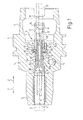
- a chuck 1 is shown in section.
- the chuck 1 has a longitudinal axis l. Along the longitudinal axis l extends a bore 2 of the chuck 1, which has sections of different diameters.
- the chuck 1 has a clamping section 3, a middle section 4 and a coupling section 5.
- the clamping section 3 is provided for a tool 6 (with dashed lines indicated), which medium channels 7 for transporting cooling or lubricating medium to a tool tip, not shown, which open into a bottom surface 8.
- a device 9 for supplying a cooling or lubricating medium to the medium channels 7 of the tool 6 is arranged in the bore 2.
- the chuck 1 is designed as a so-called Hydrodehnspannfutter, in which the tool 6 is hydraulically tensioned, wherein the pressure on the tool 6 is generated via an annular channel 11 which lies in the clamping portion 3 of the chuck 1.
- the increasing and decreasing of the pressure via an adjusting screw (not shown) which is arranged in a bore 12.
- the device 9 consists essentially of a sleeve 13, a pipe section 14 and a screw 15, wherein the tubular element 14 and the adjusting screw 15 are integrally formed as a pipe screw 16.
- the sleeve 13 has a through hole 17.
- the sleeve 13 is provided with an annular shoulder 19 and has an O-ring seal 20 in the region of the through-bore 17.
- the threaded sleeve 21 exerts pressure on the shoulder 19 of the sleeve 13 and the shoulder 19 is supported via an O-ring seal 23 against the wall 22 from.
- the conduit 10 opens into the sleeve thirteenth
- this connection of sleeve 13 and line 10 exists only when the chuck 1 is coupled to the spindle.
- the tubular element 14 is partially inserted into the sleeve 13 and is sealed relative to the sleeve 13 by the O-ring seal 20 mounted in the sleeve.
- a channel 26 formed by the tube member 14 is formed as an engagement 27 for an unillustrated adjusting tool.
- the channel 26 of the tubular element 14 merges in an oriented in the direction of the tool 6 end portion 28 in a channel 29, which passes through the integrally formed with the pipe member 14 screw 15 in the direction of the tool 6.
- the adjusting screw 15 is with an external thread G15 in an internal thread G2 of the bore 2, which passes through the chuck 1, adjustably guided. From the in the Fig. 1 shown position, the pipe screw 16 in an arrow direction z on the tool 6 is adjustable. This adjustment or longitudinal displacement takes place with the aid of the adjusting tool, not shown, which engages in the receptacle formed by the engagement 27 for a socket wrench and the pipe screw 16 relative to the chuck 1 rotates in a rotational direction w about the longitudinal axis l.
- the tubular element 14 of the pipe screw 16 is slowly pulled out of the sleeve 13 in this direction by the adjusting screw 15 in the arrow direction x, and the adjusting screw 15 moves toward the bottom surface 8 of the tool 6.
- the readjustment of the adjusting screw 15 or of the tubular element 14 is completed when an end face 30 of the adjusting screw 15 seals with the tool 6.
- the pipe screw 16 is displaced by a dimension a in the direction z, so that the pipe element 14 is not so deep in the sleeve 13 inserted.
- the device 9 allows for automatic adjustment of the clamping depth of the tool 6 a symbolically indicated lance 31 an automatic horriervorraum not shown through the sleeve 13, the tubular element 14 and the screw 15 to pass, so that it serves as a stop for the tool 6 , That is, the tool 6 is pushed in the relaxed state of the Hydrodehnspannfutters 1 to the lance 31 and then clamped in the hydraulic chuck 1, so that it is held in the specified by the lance clamping. Subsequently, the device 9 is adjusted so that the adjusting screw 15 contacts the tool 6.
- Fig. 2 is that in Fig. 1 shown chuck 1 shown again, wherein the pipe screw 16 is formed in two parts.
- the pipe screw 16 here consists of a tubular element 14 which is inserted with an end portion 28 in a channel 29 of a screw 15 and glued to it.
- the tube member 14 and the screw 15 are rotatably connected to each other.
- a rotation of a socket wrench, which engages in an engagement 27 of the tubular element 14, causes a common rotation and displacement of the tubular element 14 and the adjusting screw 15th
- the tube member 14 has an O-ring seal 32 with which this in the through hole 17 of the sleeve 15 is movable.
- it is provided to provide an engagement for a socket wrench in the screw and to dimension the channel of the tubular element and the through hole of the sleeve so that the socket wrench can engage through it into the engagement.
- the invention is not limited to illustrated or described embodiments. Rather, it includes developments of the invention within the scope of the patent claims. In particular, it is provided in a multi-part design of adjusting screw and pipe element, pipe elements of different lengths ready to form chucks with different dimensions according to the invention can. In a one-piece design of set screw and chuck components of different lengths are provided accordingly.
Landscapes
- Engineering & Computer Science (AREA)
- Mechanical Engineering (AREA)
- Gripping On Spindles (AREA)
Applications Claiming Priority (3)
| Application Number | Priority Date | Filing Date | Title |
|---|---|---|---|
| DE10307437 | 2003-02-20 | ||
| DE10312743A DE10312743A1 (de) | 2003-02-20 | 2003-03-21 | Spannfutter für ein Werkzeug |
| EP04713001.8A EP1597007B2 (de) | 2003-02-20 | 2004-02-20 | Spannfutter |
Related Parent Applications (2)
| Application Number | Title | Priority Date | Filing Date |
|---|---|---|---|
| EP04713001.8A Division-Into EP1597007B2 (de) | 2003-02-20 | 2004-02-20 | Spannfutter |
| EP04713001.8 Division | 2004-02-20 |
Publications (1)
| Publication Number | Publication Date |
|---|---|
| EP2564959A1 true EP2564959A1 (de) | 2013-03-06 |
Family
ID=32891772
Family Applications (1)
| Application Number | Title | Priority Date | Filing Date |
|---|---|---|---|
| EP11166950A Withdrawn EP2564959A1 (de) | 2003-02-20 | 2004-02-20 | Stellschraube für ein Spannfutter und damit ausgerüstetes Spannfutter für ein Werkzeug |
Country Status (7)
| Country | Link |
|---|---|
| EP (1) | EP2564959A1 (enExample) |
| JP (2) | JP4874089B2 (enExample) |
| DE (2) | DE10312743A1 (enExample) |
| DK (1) | DK1597007T3 (enExample) |
| ES (1) | ES2419387T3 (enExample) |
| PT (1) | PT1597007E (enExample) |
| SI (1) | SI1597007T1 (enExample) |
Families Citing this family (25)
| Publication number | Priority date | Publication date | Assignee | Title |
|---|---|---|---|---|
| KR101361023B1 (ko) | 2003-10-14 | 2014-02-10 | 귀링 요르크 | 샤프트 공구와 연결편 사이의 인터페이스 |
| DE102004063739B4 (de) * | 2004-12-29 | 2009-04-09 | EMUGE-Werk Richard Glimpel GmbH & Co. KG Fabrik für Präzisionswerkzeuge | Vorrichtung zum Koppeln eines Rotationswerkzeugs mit einer Werkzeugspindel sowie ein Verfahren zum Bearbeiten eines Werkstücks mit einem Rotationswerkzeug |
| DE102005013483A1 (de) * | 2005-03-23 | 2006-09-28 | Franz Haimer Maschinenbau Kg | Werkzeughalter |
| DE102005043823B4 (de) * | 2005-09-13 | 2008-07-17 | Schunk Gmbh & Co. Kg Spann- Und Greiftechnik | Spannfutter |
| DE202005016270U1 (de) * | 2005-10-14 | 2007-06-28 | Gühring Ohg | Werkzeugspannfutter, das für ein automatisches Spannen mttels einer Automatikspindel an einer Maschine ausgelegt ist |
| DE102005054718B4 (de) * | 2005-11-17 | 2013-08-08 | MAPAL Fabrik für Präzisionswerkzeuge Dr. Kress KG | Schnittstelle zwischen zwei Werkzeugelementen |
| DE102005060879A1 (de) * | 2005-12-20 | 2007-06-21 | Leeb, Mechthilde | Werkzeugaufnahme, welche zur Erstellung von Gewindeausnehmungen ins volle Material mit einer Kühlmittelanlage ausgerüstet ist, die mit Gegenströmung arbeitet |
| DE102006005665A1 (de) * | 2006-01-31 | 2007-08-02 | Bielomatik Leuze Gmbh + Co Kg | Werkzeughalter und Werkzeugmaschine mit Arbeitsspindel und Werkzeughalter |
| DE102006062973C5 (de) | 2006-04-10 | 2020-03-05 | Franz Haimer Maschinenbau Kg | System aus Werkzeughalter mit einer zylindrischen Werkzeugaufnahme in Form eines Spannzangenfutters und Werkzeug |
| DE102006037203B4 (de) * | 2006-08-09 | 2009-03-19 | MAPAL Fabrik für Präzisionswerkzeuge Dr. Kress KG | Schnittstelle |
| DE202011109498U1 (de) | 2011-12-27 | 2012-02-13 | Franz Haimer Maschinenbau Kg | Werkzeughalter und Spannsystem mit einem derartigen Werkzeughalter |
| DE202007012199U1 (de) * | 2007-08-31 | 2007-12-13 | Röhm Gmbh | Bohrfutter |
| EP2052801A1 (fr) * | 2007-09-18 | 2009-04-29 | Laip, S.A. | Adaptateur pour porte-outils à système de refroidissement employant une quantité minime de lubrifiant |
| JP5186996B2 (ja) * | 2008-05-08 | 2013-04-24 | 株式会社デンソー | 工具ホルダ |
| DE102009012433A1 (de) * | 2009-03-10 | 2010-09-16 | Kennametal Inc. | Zerspanungswerkzeug für eine Werkzeugmaschine |
| DE102010008873A1 (de) * | 2009-06-24 | 2010-12-30 | Gühring Ohg | Vorrichtung zur Abdichtung |
| JP5603937B2 (ja) * | 2009-07-07 | 2014-10-08 | グーリング オーハーゲー | 工具用チャック |
| DE102012201533A1 (de) | 2011-02-02 | 2012-08-02 | Bielomatik Leuze Gmbh + Co. Kg | Werkzeughalter und Werkzeugmaschine mit Arbeitsspindel und Werkzeughalter |
| DE102011081502A1 (de) | 2011-08-24 | 2013-02-28 | Gühring Ohg | Kühlschmiermittelzuführungssystem |
| WO2015166062A1 (de) * | 2014-04-30 | 2015-11-05 | MAPAL Fabrik für Präzisionswerkzeuge Dr. Kress KG | Werkzeughalter |
| DE102015120971A1 (de) | 2015-12-02 | 2017-06-08 | Gühring KG | Hydrodehnspannfutter/Hydraulik-Dehnspannfutter |
| DE102019209732A1 (de) * | 2019-07-03 | 2021-01-07 | Gühring KG | Hydrodehnspannfutter |
| DE102019216826B4 (de) | 2019-10-31 | 2024-12-12 | Gühring KG | Hydrodehnspannfutter |
| CN114669766B (zh) * | 2022-04-15 | 2024-05-17 | 纽威数控装备(苏州)股份有限公司 | 一种伸缩主轴降温结构 |
| DE102022117257B4 (de) * | 2022-07-11 | 2025-01-16 | E. Zoller GmbH & Co. KG Einstell- und Messgeräte | Längeneinstellvorrichtung zu einer Einstellung einer Längsposition eines Werkzeugs, Werkzeugspanngerät und System und Verfahren mit der Längeneinstellvorrichtung |
Citations (12)
| Publication number | Priority date | Publication date | Assignee | Title |
|---|---|---|---|---|
| JPS5990505U (ja) * | 1982-12-07 | 1984-06-19 | 三菱自動車工業株式会社 | 工作機械用工具ホルダ |
| FR2638991A1 (fr) * | 1988-11-15 | 1990-05-18 | Pfalzgraf Emile Epb Sa | Dispositif de montage a queue conique, en particulier au cone 7/24, a application cone et face pour attachements, porte-outils et outils |
| JPH05212651A (ja) * | 1992-02-04 | 1993-08-24 | Mitsubishi Materials Corp | 切削機械 |
| JPH08155710A (ja) * | 1994-11-30 | 1996-06-18 | Nikken Kosakusho:Kk | 工具取付装置に用いられる位置決め具 |
| EP0776728A1 (de) * | 1995-08-05 | 1997-06-04 | Joh. & Ernst Link GmbH & Co. KG | Kombinationswerkzeug |
| JP2000042814A (ja) * | 1998-07-28 | 2000-02-15 | Yukiwa Seiko Inc | チャック装置 |
| DE19935960A1 (de) | 1999-07-30 | 2001-02-01 | Bielomatik Leuze & Co | Zuführung für Medien an ein Werkzeug |
| EP1127656A1 (en) * | 1998-09-11 | 2001-08-29 | Horkos Corp | Tool holder for machine tool |
| DE10015322A1 (de) * | 2000-03-28 | 2001-10-18 | Zoller Gmbh & Co Kg E | Verfahren zum Einstellen eines Einstellmaßes eines Werkzeuges |
| EP1203631A1 (en) * | 1999-07-09 | 2002-05-08 | Horkos Corp | Spindle device and tool holder of machine tool |
| EP1206990A1 (de) * | 2000-11-15 | 2002-05-22 | Josef Albrecht Bohrfutterfabrik GmbH + Co | Axial-Spannfutter |
| EP1561539A1 (en) * | 2002-07-18 | 2005-08-10 | Horkos Corp | Tool holder of machine tool |
Family Cites Families (5)
| Publication number | Priority date | Publication date | Assignee | Title |
|---|---|---|---|---|
| JP2512031B2 (ja) * | 1987-11-10 | 1996-07-03 | 松下電器産業株式会社 | デ―タ通信方式 |
| JPH0750119Y2 (ja) * | 1988-02-19 | 1995-11-15 | 富士精工株式会社 | 液密式工具ホルダ |
| JP2502466Y2 (ja) * | 1993-09-20 | 1996-06-26 | 富士精工株式会社 | 工具ホルダのトルク伝達装置 |
| JPH1029106A (ja) * | 1996-07-12 | 1998-02-03 | Daishowa Seiki Co Ltd | ハイドロリックチャック装置 |
| JP3083291B1 (ja) * | 1999-03-19 | 2000-09-04 | 株式会社日研工作所 | 工具ホルダ |
-
2003
- 2003-03-21 DE DE10312743A patent/DE10312743A1/de not_active Withdrawn
-
2004
- 2004-02-20 DK DK04713001.8T patent/DK1597007T3/da active
- 2004-02-20 PT PT04713001T patent/PT1597007E/pt unknown
- 2004-02-20 ES ES04713001T patent/ES2419387T3/es not_active Expired - Lifetime
- 2004-02-20 EP EP11166950A patent/EP2564959A1/de not_active Withdrawn
- 2004-02-20 JP JP2006501511A patent/JP4874089B2/ja not_active Expired - Fee Related
- 2004-02-20 DE DE200420021846 patent/DE202004021846U1/de not_active Expired - Lifetime
- 2004-02-20 SI SI200432003T patent/SI1597007T1/sl unknown
-
2011
- 2011-03-22 JP JP2011063418A patent/JP5147965B2/ja not_active Expired - Fee Related
Patent Citations (13)
| Publication number | Priority date | Publication date | Assignee | Title |
|---|---|---|---|---|
| JPS5990505U (ja) * | 1982-12-07 | 1984-06-19 | 三菱自動車工業株式会社 | 工作機械用工具ホルダ |
| FR2638991A1 (fr) * | 1988-11-15 | 1990-05-18 | Pfalzgraf Emile Epb Sa | Dispositif de montage a queue conique, en particulier au cone 7/24, a application cone et face pour attachements, porte-outils et outils |
| JPH05212651A (ja) * | 1992-02-04 | 1993-08-24 | Mitsubishi Materials Corp | 切削機械 |
| JPH08155710A (ja) * | 1994-11-30 | 1996-06-18 | Nikken Kosakusho:Kk | 工具取付装置に用いられる位置決め具 |
| EP0776728A1 (de) * | 1995-08-05 | 1997-06-04 | Joh. & Ernst Link GmbH & Co. KG | Kombinationswerkzeug |
| JP2000042814A (ja) * | 1998-07-28 | 2000-02-15 | Yukiwa Seiko Inc | チャック装置 |
| EP1127656B1 (en) | 1998-09-11 | 2004-04-28 | Horkos Corp | Tool holder for machine tool |
| EP1127656A1 (en) * | 1998-09-11 | 2001-08-29 | Horkos Corp | Tool holder for machine tool |
| EP1203631A1 (en) * | 1999-07-09 | 2002-05-08 | Horkos Corp | Spindle device and tool holder of machine tool |
| DE19935960A1 (de) | 1999-07-30 | 2001-02-01 | Bielomatik Leuze & Co | Zuführung für Medien an ein Werkzeug |
| DE10015322A1 (de) * | 2000-03-28 | 2001-10-18 | Zoller Gmbh & Co Kg E | Verfahren zum Einstellen eines Einstellmaßes eines Werkzeuges |
| EP1206990A1 (de) * | 2000-11-15 | 2002-05-22 | Josef Albrecht Bohrfutterfabrik GmbH + Co | Axial-Spannfutter |
| EP1561539A1 (en) * | 2002-07-18 | 2005-08-10 | Horkos Corp | Tool holder of machine tool |
Non-Patent Citations (1)
| Title |
|---|
| "Induktives Schrumpfgerät GISS 3000 im Katalog", 2002, article "Präzisions-Schneidwerkzeuge", pages: 958 |
Also Published As
| Publication number | Publication date |
|---|---|
| ES2419387T3 (es) | 2013-08-20 |
| JP2011115946A (ja) | 2011-06-16 |
| JP5147965B2 (ja) | 2013-02-20 |
| DE10312743A1 (de) | 2004-09-23 |
| JP2006518280A (ja) | 2006-08-10 |
| PT1597007E (pt) | 2013-03-28 |
| SI1597007T1 (sl) | 2013-04-30 |
| JP4874089B2 (ja) | 2012-02-08 |
| DE202004021846U1 (de) | 2011-09-27 |
| DK1597007T3 (da) | 2013-04-02 |
Similar Documents
| Publication | Publication Date | Title |
|---|---|---|
| EP1597007B1 (de) | Spannfutter | |
| EP2564959A1 (de) | Stellschraube für ein Spannfutter und damit ausgerüstetes Spannfutter für ein Werkzeug | |
| EP1529585B1 (de) | Dehnspanneinrichtung | |
| DE69714781T2 (de) | Hydromechanisches futter | |
| DE102005013483A1 (de) | Werkzeughalter | |
| EP1529584A1 (de) | Zwischenbüchse für ein Spannfutter und Verfahren zu deren Herstellung | |
| EP1693134A2 (de) | Gewindebohreraufnahme | |
| EP0086379B1 (de) | Werkzeugwechsler | |
| EP2956254B1 (de) | Bördelaufsatz zum aufweiten von zylindrischen rohrenden | |
| EP1233848A1 (de) | Honahle | |
| DE19861489B4 (de) | Verfahren und Vorrichtung zur Einspeisung von Kühl- und Schmiermittel in ein Werkzeug | |
| EP2145710B1 (de) | Vorrichtung zur Nachbearbeitung einer Aufnahmebohrung für Glühkerzen | |
| EP1934008B1 (de) | Werkzeugspannfutter, das für ein automatisches spannen mittels einer automatikspindel an einer maschine ausgelegt ist | |
| EP2103369B1 (de) | Dehnspannfutter | |
| DE20321408U1 (de) | Spannfutter für ein Werkzeug | |
| EP3275589B1 (de) | Arbeitsspindel-kühleinrichtung und werkzeugmaschinen-bearbeitungseinheit mit einer derartigen arbeitspindel-kühleinrichtung | |
| DE102005043823B4 (de) | Spannfutter | |
| DE19960510C1 (de) | Rammgerät | |
| DE19512591C2 (de) | Anbohrarmatur für insbesondere unter Mediendruck stehende Rohre, wie Gas- oder Wasserrohre | |
| AT518874B1 (de) | Bearbeitungsmaschine | |
| DE102006005665A1 (de) | Werkzeughalter und Werkzeugmaschine mit Arbeitsspindel und Werkzeughalter | |
| EP1159105A1 (de) | Spannfutter | |
| DE102009007456B4 (de) | Verstellbare Reibahle | |
| DE102011081506B4 (de) | Rundlaufendes Zerspanungswerkzeug | |
| AT509138B1 (de) | Anbohrgerät |
Legal Events
| Date | Code | Title | Description |
|---|---|---|---|
| PUAI | Public reference made under article 153(3) epc to a published international application that has entered the european phase |
Free format text: ORIGINAL CODE: 0009012 |
|
| AC | Divisional application: reference to earlier application |
Ref document number: 1597007 Country of ref document: EP Kind code of ref document: P |
|
| AK | Designated contracting states |
Kind code of ref document: A1 Designated state(s): AT BE BG CH CY CZ DE DK EE ES FI FR GB GR HU IE IT LI LU MC NL PT RO SE SI SK TR |
|
| 17P | Request for examination filed |
Effective date: 20130906 |
|
| RBV | Designated contracting states (corrected) |
Designated state(s): AT BE BG CH CY CZ DE DK EE ES FI FR GB GR HU IE IT LI LU MC NL PT RO SE SI SK TR |
|
| 17Q | First examination report despatched |
Effective date: 20160621 |
|
| STAA | Information on the status of an ep patent application or granted ep patent |
Free format text: STATUS: THE APPLICATION IS DEEMED TO BE WITHDRAWN |
|
| 18D | Application deemed to be withdrawn |
Effective date: 20200901 |