EP2562727B1 - Selbstbedienungsvorrichtung für Waren - Google Patents
Selbstbedienungsvorrichtung für Waren Download PDFInfo
- Publication number
- EP2562727B1 EP2562727B1 EP20120005101 EP12005101A EP2562727B1 EP 2562727 B1 EP2562727 B1 EP 2562727B1 EP 20120005101 EP20120005101 EP 20120005101 EP 12005101 A EP12005101 A EP 12005101A EP 2562727 B1 EP2562727 B1 EP 2562727B1
- Authority
- EP
- European Patent Office
- Prior art keywords
- output
- product
- self
- storage space
- service device
- Prior art date
- Legal status (The legal status is an assumption and is not a legal conclusion. Google has not performed a legal analysis and makes no representation as to the accuracy of the status listed.)
- Not-in-force
Links
- 238000004806 packaging method and process Methods 0.000 claims description 2
- 238000000926 separation method Methods 0.000 claims 9
- 230000002093 peripheral effect Effects 0.000 description 3
- 235000013361 beverage Nutrition 0.000 description 2
- 239000000284 extract Substances 0.000 description 2
- 241000208125 Nicotiana Species 0.000 description 1
- 235000002637 Nicotiana tabacum Nutrition 0.000 description 1
- 230000005484 gravity Effects 0.000 description 1
Images



Classifications
-
- A—HUMAN NECESSITIES
- A47—FURNITURE; DOMESTIC ARTICLES OR APPLIANCES; COFFEE MILLS; SPICE MILLS; SUCTION CLEANERS IN GENERAL
- A47F—SPECIAL FURNITURE, FITTINGS, OR ACCESSORIES FOR SHOPS, STOREHOUSES, BARS, RESTAURANTS OR THE LIKE; PAYING COUNTERS
- A47F1/00—Racks for dispensing merchandise; Containers for dispensing merchandise
- A47F1/04—Racks or containers with arrangements for dispensing articles, e.g. by means of gravity or springs
- A47F1/08—Racks or containers with arrangements for dispensing articles, e.g. by means of gravity or springs dispensing from bottom
-
- G—PHYSICS
- G07—CHECKING-DEVICES
- G07F—COIN-FREED OR LIKE APPARATUS
- G07F11/00—Coin-freed apparatus for dispensing, or the like, discrete articles
- G07F11/005—Special arrangements for insuring that only one single article may be dispensed at a time
-
- G—PHYSICS
- G07—CHECKING-DEVICES
- G07F—COIN-FREED OR LIKE APPARATUS
- G07F11/00—Coin-freed apparatus for dispensing, or the like, discrete articles
- G07F11/02—Coin-freed apparatus for dispensing, or the like, discrete articles from non-movable magazines
- G07F11/04—Coin-freed apparatus for dispensing, or the like, discrete articles from non-movable magazines in which magazines the articles are stored one vertically above the other
Definitions
- the invention relates to a self-service device for goods, preferably for placement in the area of cash registers in supermarkets and the like.
- Salesrooms in which at least one storage space stacked goods in particular cylindrical shape such as cans, bottles and the like. Filled packaged individually removable and to a Issue are eligible, wherein the storage space is associated with a movable conveyor, which promotes a dispensed goods from the storage room to the output.
- Such self-service devices are for example from the EP 0 311 603 B1 which discloses a dispensing device in which a collection container located above a checkout counter and a delivery chute which can be displaced into the vicinity of a checkout are provided, via which selected goods can be dispensed by gravity from the overhead container.
- the self-service device of the aforementioned is characterized in that in the output area of the storage space a goods to be dispensed during the output conveying movement by the conveyor holding separating device is provided, which during the output conveyor movement of the dispensed goods stacked above the goods to be dispensed in the storage room goods holding with a holder in their storage positions.
- a self-service device for goods is created, with which even cylindrical products, in particular product packaging with a circular peripheral surface or a cylindrical outer surface, can be safely issued individually.
- the separating device in the discharge area of the storage space ensures that only one commodity that has been selected is positioned and held during the output conveying movement for one dispensing operation, while the other products still in the storage space are held in their stocking positions.
- a movement of further goods stored in the storage space is blocked by the holder of the separating device. Only when the goods are issued, the separating device free their receiving space so that a next product can move up. If it then comes back to a selection of this product, the output conveyor movement can be performed again, during which the other products are held in their storage position by the holder during these further output conveyor movements.
- a holder is preferably provided for holding the product to be dispensed on the separating device, in particular a holding bracket in e.g. essentially U-shaped shape, which delimits the goods to be dispensed in the output conveying direction, so that the goods can only leave the dispensing unit when a dispensing opening is released, which allows taking into account the position of the holder or the retaining clip that the goods to be dispensed From their dimensions, the opening can happen.
- a holding bracket in e.g. essentially U-shaped shape, which delimits the goods to be dispensed in the output conveying direction, so that the goods can only leave the dispensing unit when a dispensing opening is released, which allows taking into account the position of the holder or the retaining clip that the goods to be dispensed From their dimensions, the opening can happen.
- the separating device is designed to be movable in such a way that it carries out an output conveying movement, which is introduced and performed by the conveyor.
- the separating device is therefore preferably coupled in terms of movement with the conveyor. If the conveyor makes a movement toward the dispensing opening of the dispenser, the singulator also performs a movement.
- the conveyor makes a movement toward the dispensing opening of the dispenser, the singulator also performs a movement.
- it is preferably pivotally mounted on a wall of the storage space in the manner of a pendulum, so that the device provided on the holder during the conveying movement reaches a position, namely automatically, in which he engages the stacked above the goods to be dispensed further goods, by lying below the next adjacent goods.
- the stacked further goods on the holder of this separating apparatus based, until such time as the conveyor and thus also the separating device perform an opposing return movement, through which the holder can be transferred back into a recessed position and in this initial position then allowed to move on again a next product.
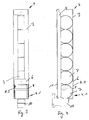
- a self-service device with an output unit 2 is numbered. This has several translationally movable extracts 5 with limited by side walls 3 goods receiving spaces. 4
- FIG. 2 such a receiving space 4 is illustrated in more detail.
- This is partially bounded by side walls 3 and has taken in the illustrated embodiment cylindrical goods or products.
- This can be beverage cans, bottles, but also, for example, tobacco cans, coffee cans and the like.
- the dispensing area 4.1 is provided with an outlet opening 4.2.
- This dispensing opening 4.2 is bounded at the top by a transverse web 6.
- the output opening 4.2 for the lower product 7 is still closed by a bracket 8 a later to be explained in more detail singulation device 9.
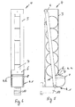
- the output area 4.1 of the storage space 4 is also associated with a translationally movable conveyor 10, which is located in Fig. 2 is in its initial or rest position. This rest position is also in the Fig. 3, 4 and 7 illustrated.
- the separating device 9 can be seen, on which the headband 8 is attached.
- the separating device 9 is pivotally attached to the wall 3 of the storage space 4 and in terms of movement with the conveyor 10 coupled.
- the pivotable separating device 9 is formed in the embodiment shown as a double pivoting pendulum in the sense that they extend with a small distance to each of the two end faces of the can-shaped packages 7 and thus can move laterally during a pivoting movement of the stored goods over.
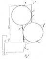
- Fig. 5 the situation is shown, which results when a product has been selected by a customer.
- the conveyor 10 is activated, which performs a translational movement forward.
- the separating device 9 is designed to be coupled in a coupled manner with the conveyor 10, it performs a pivoting movement about its pivot axis towards the front.
- the headband remains in its position on the double pivoting pendulum of the separating device 9, since it extends approximately over the entire width of the outlet opening 4.2 and thus holds the goods 7 significantly techde so long until their distance from the storage space and the conveyor is so large that the goods can fall out of the storage space through the outlet opening 4.2 of the dispensing area 4.1.
- the conveying movement, the bracket 8 towards the front and the width and height of the outlet opening 4.2 are coordinated.
Landscapes
- Physics & Mathematics (AREA)
- General Physics & Mathematics (AREA)
- De-Stacking Of Articles (AREA)
Description
- Die Erfindung bezieht sich auf eine Selbstbedienungsvorrichtung für Waren, vorzugsweise zur Anordnung im Bereich von Kassenanlagen in Supermärkten und dgl. Verkaufsräumen, bei der in zumindest einem Aufbewahrungsraum übereinander gestapelte Waren in insbesondere Zylinderform wie Dosen, Flaschen und dgl. befüllte Warenverpackungen einzeln entnehmbar und zu einer Ausgabe förderbar sind, wobei dem Aufbewahrungsraum ein bewegbarer Förderer zugeordnet ist, der eine auszugebende Ware von dem Aufbewahrungsraum zu der Ausgabe fördert.
- Derartige Selbstbedienungsvorrichtungen sind beispielsweise aus der
EP 0 311 603 B1 bekannt, die eine Abgabevorrichtung offenbart, bei der ein oberhalb eines Kassentisches befindlicher Sammelbehälter und ein in den Nahbereich einer Kasse verlagerbarer Förderschacht vorgesehen sind, über den ausgewählte Waren unter Schwerkraftwirkung aus dem oben liegenden Behälter ausgegeben werden können. - Auszuwählende und auszugebende Waren jedoch nicht quaderförmig, sondern haben eine eher zylindrische Gestalt, wie dies beispielsweise bei Dosen und Getränkeflaschen der Fall ist, bereiten die Selbstbedienungsvorrichtungen herkömmlicher Ausbildung Probleme, weil bei diesen das Risiko besteht, dass aufgrund der kreisförmigen Produktgestaltung nicht sicher nur ein einzelnes Produkt ausgegeben wird. Vielmehr besteht das nicht unerhebliche Risiko, dass bei Auswählen eines Produktes mehrere Produkte ausgebracht werden.
- Gemäß einer Lösung in
US 2004/0030444 A1 wird eine Wannen- oder Schalenstruktur zur Aufnahme der Waren vorgesehen. Diese Aufnahme wirkt mit einem motorisch angetriebenen Schwenkmechanismus zusammen, so dass ein insgesamt aufwändiges Bediensystem vorliegt. - Es ist Aufgabe der Erfindung, eine Selbstbedienungsvorrichtung der eingangs genannten Art derart weiter zu bilden, dass mit dieser auch sicher ein Einzelprodukt ausgegeben werden kann, wenn dieses eine zylindrische oder eine andere Gestalt mit einer kreisförmigen Umfangsfläche hat.
- Zur Lösung dieser Aufgabe zeichnet sich die Selbstbedienungsvorrichtung der eingangs genannten dadurch aus, dass im Ausgabebereich des Aufbewahrungsraumes eine die auszugebende Ware während der Ausgabeförderbewegung durch die Förderer haltende Vereinzelungsvorrichtung vorgesehen ist, die während der Ausgabeförderbewegung der auszugebenden Ware die oberhalb der auszugebenden Ware im Aufbewahrungsraum gestapelten Waren mit einem Halter in ihren Bevorratungspositionen hält.
- Damit ist eine Selbstbedienungsvorrichtung für Waren geschaffen, mit der auch zylindrische Produkte, insbesondere Warenverpackungen mit einer kreisförmigen Umfangsfläche oder einer zylindrischen Mantelfläche, sicher einzeln ausgegeben werden können. Die Vereinzelungsvorrichtung im Ausgabebereich des Aufbewahrungsraumes stellt sicher, dass nur eine Ware, die ausgewählt wurde, während der Ausgabeförderbewegung für einen Ausgabevorgang positioniert und gehalten wird, während die anderen noch im Aufbewahrungsraum befindlichen Produkte bzw. Waren in ihren Bevorratungspositionen gehalten werden. Solange die Vereinzelungsvorrichtung die ausgebende Ware noch hält, ist ein Nachrücken von weiteren im Aufbewahrungsraum bevorrateten Waren durch den Halter der Vereinzelungsvorrichtung blockiert. Erst wenn die Ware ausgegeben ist, gibt die Vereinzelungsvorrichtung ihren Aufnahmeraum frei, so dass ein nächstes Produkt nachrücken kann. Kommt es dann wieder zu einem Auswählen dieser Ware, kann die Ausgabeförderbewegung wieder ausgeführt werden, wobei auch während dieser weiteren Ausgabeförderbewegungen die anderen Produkte in ihrer Bevorratungsposition durch den Halter gehalten werden.
- Bevorzugtermaßen ist für das Halten der auszugebenden Ware an der Vereinzelungsvorrichtung ein Halter vorgesehen, insbesondere ein Haltebügel in z.B. im wesentlichen U-förmiger Gestalt, der die auszugebende Ware in Ausgabeförderrichtung umgrenzt, so dass die Ware erst dann die Ausgabeeinheit verlassen kann, wenn eine Ausgabeöffnung freigegeben wird, die es unter Berücksichtigung der Lage des Halters bzw. des Haltebügels erlaubt, dass die auszugebende Ware von ihren Abmessungen her die Öffnung passieren kann.
- Bevorzugtermaßen ist die Vereinzelungsvorrichtung bewegbar ausgebildet und zwar dergestalt, dass diese eine Ausgabeförderbewegung ausführt, die durch den Förderer eingeleitet und durchgeführt wird. Die Vereinzelungsvorrichtung ist daher bevorzugtermaßen bewegungsmäßig gekoppelt mit dem Förderer. Macht der Förderer eine Bewegung hin in Richtung der Ausgabeöffnung der Ausgabe, führt die Vereinzelungsvorrichtung ebenfalls eine Bewegung aus. Dazu ist sie bevorzugtermaßen schwenkbar an einer Wandung des Aufbewahrungsraums nach Art eines Pendels befestigt, so dass auch der an der Vereinzelungsvorrichtung vorgesehene Halter während der Förderbewegung in eine Position gelangt, und zwar automatisch, in der er die oberhalb der auszugebenden Ware gestapelten weiteren Waren untergreift, indem er unterhalb der nächst benachbarten Ware zu liegen kommt. Somit stützen sich während der Förderbewegung die übereinander gestapelten weiteren Waren auf dem Halter dieser Vereinzelungsvorrichtung ab, und zwar so lange, bis der Förderer und damit auch die Vereinzelungsvorrichtung eine gegensinnige Rückbewegung durchführen, durch die auch der Halter wieder in eine rückversetzte Lage überführt werden kann und in dieser Ausgangslage dann wieder ein Nachrücken einer nächsten Ware erlaubt.
- Hinsichtlich wesentlicher weiterer Ausgestaltungen wird auf weitere Unteransprüche, die nachfolgende Beschreibung und die Zeichnung verwiesen. In der Zeichnung zeigen:
- Fig. 1
- in einer schematischen perspektivischen Darstellung eine Selbstbedienungsvorrichtung mit einzelnen translatorisch bewegbaren Auszügen mit mehreren nebeneinander angeordneten Aufbewahrungsräumen,
- Fig. 2
- in einer perspektivischen Darstellung einen von Seitenwänden umgrenzten Aufbewahrungsraum,
- Fig. 3
- eine Ansicht von vorne auf den Aufbewahrungsraum,
- Fig. 4
- das Ausführungsbeispiel nach
Fig. 3 in einer Seitenansicht, bei der sich die Vereinzelungsvorrichtung und der Förderer in ihrer Ausgangs- bzw. Ruhestellung befinden, - Fig. 5
- eine zur
Fig. 4 analoge Darstellung, bei der der Föderer und die Vereinzelungsvorrichtung sich in einer Stellung während einer Ausgabeförderbewegung befinden, - Fig. 6
- eine zu
Fig. 3 analoge Darstellung in der Stellung der Teile nachFig. 5 , - Fig. 7
- vergrößert den Bereich des Aufbewahrungsraumes in der Stellung gemäß
Fig. 4 , und - Fig. 8
- vergrößert den unteren Bereich des Aufbewahrungsraumes gemäß der Stellung der Teile während der Ausgabeförderbewegung, wie in
Fig. 5 gezeigt. - In der Zeichnung sind übereinstimmende Teile mit übereinstimmenden Bezugsziffern versehen.
- Allgemein mit 1 ist eine Selbstbedienungsvorrichtung mit einer Ausgabeeinheit 2 beziffert. Diese hat mehrere translatorisch bewegbare Auszüge 5 mit von Seitenwänden 3 begrenzten Warenaufnahmeräumen 4.
- In
Fig. 2 ist ein solcher Aufnahmeraum 4 näher veranschaulicht. Dieser ist von Seitenwänden 3 bereichsweise umgrenzt und hat in dem dargestellten Ausführungsbeispiel zylinderförmige Waren bzw. Produkte aufgenommen. Dies können Getränkedosen sein, Flaschen, aber auch beispielsweise Tabakdosen, Kaffeedosen und dgl. mit einer kreisrunden Umfangsfläche versehene Warenverpackungen. Denkbar ist auch, dass an Stelle der mit einer zylindrischen Mantelfläche versehenen Waren auch solche mit kugelförmiger, kreiskegelförmiger oder tonnenförmiger Gestalt vorgesehen sind (nicht dargestellt). - Im unteren Bereich des Aufbewahrungsraumes 4 ist der Ausgabebereich 4.1 mit einer Ausgabeöffnung 4.2 vorgesehen. Diese Ausgabeöffnung 4.2 wird nach oben hin von einem Quersteg 6 begrenzt. In der in
Fig. 2 dargestellten Stellung der Teile kann die untere Dosenverpackung den Ausgabebereich noch nicht verlassen, weil die Ausgabeöffnung 4.2 für die untere Ware 7 noch von einem Haltebügel 8 einer später noch näher zu erläuternden Vereinzelungsvorrichtung 9 verschlossen ist. - Dem Ausgabebereich 4.1 des Aufbewahrungsraumes 4 ist darüber hinaus ein translatorisch bewegbarer Förderer 10 zugeordnet, der sich in
Fig. 2 in seiner Ausgangs- bzw. Ruhestellung befindet. Diese Ruhestellung ist auch in denFig. 3, 4 und7 veranschaulicht. In der Darstellung nachFig. 4 ist darüber hinaus die Vereinzelungsvorrichtung 9 ersichtlich, an der der Haltebügel 8 befestigt ist. In dem dargestellten Ausführungsbeispiel ist die Vereinzelungsvorrichtung 9 schwenkbar an der Wandung 3 des Aufbewahrungsraumes 4 befestigt und bewegungstechnisch mit dem Förderer 10 gekoppelt. Die schwenkbare Vereinzelungsvorrichtung 9 ist in dem gezeigten Ausführungsbeispiel als Doppelschwenkpendel in dem Sinne ausgebildet, dass sie sich mit einem geringen Abstand jeweils zu beiden Stirnflächen der dosenförmigen Verpackungen 7 erstrecken und sich somit während einer Schwenkbewegung jeweils seitlich an den bevorrateten Waren vorbei bewegen können. - In
Fig. 5 ist die Situation gezeigt, die sich ergibt, wenn von einem Kunden eine Ware angewählt wurde. Damit wird der Förderer 10 aktiviert, der eine translatorische Bewegung nach vorne durchführt. Da die Vereinzelungsvorrichtung 9 bewegungsgekoppelt mit dem Förderer 10 ausgebildet ist, führt sie um ihre Schwenkachse eine Schwenkbewegung nach vorne hin durch. Dabei verbleibt der Haltebügel in seiner Position am doppelten Schwenkpendel der Vereinzelungsvorrichtung 9, da er sich annähernd über die gesamte Breite der Auslassöffnung 4.2 erstreckt und somit die auszubringende Ware 7 so lange festhält, bis ihr Abstand zu dem Aufbewahrungsraum und dem Förderer so groß ist, dass die Ware aus dem Aufbewahrungsraum durch die Auslassöffnung 4.2 des Ausgabebereiches 4.1 fallen kann. Dazu sind die Förderbewegung, der Haltebügel 8 nach vorne hin und die Breite und Höhe der Auslassöffnung 4.2 aufeinander abgestimmt. - Im hinteren Bereich des jeweiligen Pendels der Vereinzelungsvorrichtung 9 ist ein sich quer von einem Pendel zum anderen hin erstreckender Halter 11 ersichtlich, der sich in
Fig. 4 in der Ruhestellung der Teile noch hinter den bevorrateten und gestapelten Waren 7 befindet. Während der Ausgabeförderbewegung schwenkt dieser Halter 11 mit der Vereinzelungsvorrichtung 9 mit, kommt dabei automatisch unter die der auszugebenden Ware 7 benachbarte Ware zu liegen, so dass sich der Stapel der noch in den Aufbewahrungsraum 4 befindlichen weiteren Waren an diesem Halter abstützen, so dass diese sicher in dem Aufbewahrungsraum 4 gehalten werden können. Während der Schwenkbewegung ist es auch möglich, dass die noch weiter bevorrateten Waren 7 leicht angehoben werden. Durch den Halter 11 ist jedoch sichergestellt, dass noch weiter zu bevorratende Waren 7 nicht unkontrolliert nach unten fallen können und beispielsweise unbeabsichtigt durch die Ausgabeöffnung 4.2 nachrutschen. - Erst wenn der Förderer 10 wieder zurückgefahren wird unter Mitnahme der Vereinzelungsvorrichtung 9, gelangt der Halter 11 mit dem Pendel der Vereinzelungsvorrichtung 9 wieder in seine Ausgangslage, wie in
Fig. 7 dargestellt, so dass in diesem Fall ein nachfolgendes Produkt freigegeben ist und mithin der Stapel nach unten fallen kann. Dann befindet sich wiederum ein Produkt in dem unteren Ausgabebereich 4.1, ist jedoch wieder von dem Haltebügel 8 bereichsweise umgrenzt.
Claims (10)
- Selbstbedienungsvorrichtung (1) für Waren, vorzugsweise zur Anordnung im Bereich von Kassenanlagen in Supermärkten und dgl. Verkaufsräumen, bei der in zumindest einem Aufbewahrungsraum (4) übereinander gestapelte Waren (7) in insbesondere Zylinderform wie Dosen, Flaschen und dgl. befüllte Warenverpackungen einzeln entnehmbar und zu einem Ausgabebereich (4.1) förderbar sind, wobei dem Aufbewahrungsraum (4) ein bewegbarer Förderer zugeordnet ist, der eine auszugebende Ware von dem Aufbewahrungsraum (4) hin zu dem Ausgabebereich (4.1) fördert, dadurch gekennzeichnet, dass im Ausgabebereich (4.1) des Aufbewahrungsraumes (4) eine die auszugebende Ware (7) während der Ausgabeförderbewegung durch einen translatorisch bewegbaren Förderer (10) haltende Vereinzelungsvorrichtung (9) vorgesehen ist, die während der Ausgabeförderbewegung der auszugebenden Ware (7) die oberhalb der auszugebenden Ware (7) im Aufbewahrungsraum (4) gestapelten Waren mit einem Halter (11) in ihren Bevorratungspositionen hält.
- Selbstbedienungsvorrichtung nach Anspruch 1, dadurch gekennzeichnet, dass die Vereinzelungsvorrichtung (9) einen die auszugebende Ware (7) während der Ausgabeförderbewegung bereichsweise umgrenzenden Haltebügel (8) aufweist.
- Selbstbedienungsvorrichtung nach Anspruch 1 oder 2, dadurch gekennzeichnet, dass der translatorisch bewegbare Förderer (10) der Vereinzelungsvorrichtung (9) ihre Ausgabeförderbewegung erteilt.
- Selbstbedienungsvorrichtung nach einem der Ansprüche 1 bis 3, dadurch gekennzeichnet, dass die Vereinzelungsvorrichtung (9) schwenkbar ausgebildet ist.
- Selbstbedienungsvorrichtung nach einem der Ansprüche 1 bis 4, dadurch gekennzeichnet, dass die Vereinzelungsvorrichtung (9) als Schwenkpendel ausgebildet und innerhalb des Aufbewahrungsraumes (4) angeordnet ist.
- Selbstbedienungsvorrichtung nach einem der Ansprüche 1 bis 5, dadurch gekennzeichnet, dass die Vereinzelungsvorrichtung (9) an einer den Aufbewahrungsraum (4) begrenzenden Wand (3) schwenkbar gelagert ist.
- Selbstbedienungsvorrichtung nach einem der Ansprüche 1 bis 6, dadurch gekennzeichnet, dass die Vereinzelungsvorrichtung (9) einen Halter (11) aufweist, der während der Ausgabeförderbewegung der auszugebenden Ware (7) die oberhalb der auszugebenden Ware (7) gestapelten Waren untergreift.
- Selbstbedienungsvorrichtung nach einem der Ansprüche 1 bis 7, dadurch gekennzeichnet, dass die Vereinzelungsvorrichtung (9) neben den gestapelten Waren jeweils an ihren Stirnseiten nach Art eines doppelten Schwenkpendels angeordnet ist.
- Selbstbedienungsvorrichtung nach Anspruch 7 und 8, dadurch gekennzeichnet, dass sich der Halter (11) zwischen zwei Schwenkpendelbügeln erstreckt.
- Selbstbedienungsvorrichtung nach einem der Ansprüche 1 bis 9, dadurch gekennzeichnet, dass die Auslassöffnung (4.2) des Aufbewahrungsraumes (4) und der die auszugebende Ware (7) bereichsweise begrenzende Haltebügel (8) eine derart aufeinander abgestimmte Höhe und/oder Länge haben, dass die auszugebende Ware (7) den Aufbewahrungsraum (4) in der Stellung die Ausgabeöffnung (4.2) verlässt, in der der Halter (11) die oberhalb der auszugebende Ware (7) gestapelten Waren noch untergreift.
Applications Claiming Priority (1)
| Application Number | Priority Date | Filing Date | Title |
|---|---|---|---|
| DE201110110797 DE102011110797B3 (de) | 2011-08-22 | 2011-08-22 | Selbstbedienungsvorrichtung für Waren |
Publications (2)
| Publication Number | Publication Date |
|---|---|
| EP2562727A1 EP2562727A1 (de) | 2013-02-27 |
| EP2562727B1 true EP2562727B1 (de) | 2015-03-04 |
Family
ID=46581690
Family Applications (1)
| Application Number | Title | Priority Date | Filing Date |
|---|---|---|---|
| EP20120005101 Not-in-force EP2562727B1 (de) | 2011-08-22 | 2012-07-10 | Selbstbedienungsvorrichtung für Waren |
Country Status (2)
| Country | Link |
|---|---|
| EP (1) | EP2562727B1 (de) |
| DE (1) | DE102011110797B3 (de) |
Families Citing this family (1)
| Publication number | Priority date | Publication date | Assignee | Title |
|---|---|---|---|---|
| US12510292B2 (en) | 2023-12-05 | 2025-12-30 | Bsh Home Applicances Corporation | Can rack system with openings dimensioned to protect the can rack system |
Family Cites Families (3)
| Publication number | Priority date | Publication date | Assignee | Title |
|---|---|---|---|---|
| US2369882A (en) * | 1943-09-21 | 1945-02-20 | John B Brock | Vending machine |
| US4645036A (en) * | 1983-12-12 | 1987-02-24 | Nestler Richard F | Product dispenser |
| US7032776B2 (en) * | 2002-08-08 | 2006-04-25 | The Vendo Company | Vending machine bucket drive control |
-
2011
- 2011-08-22 DE DE201110110797 patent/DE102011110797B3/de not_active Expired - Fee Related
-
2012
- 2012-07-10 EP EP20120005101 patent/EP2562727B1/de not_active Not-in-force
Also Published As
| Publication number | Publication date |
|---|---|
| DE102011110797B3 (de) | 2012-12-06 |
| EP2562727A1 (de) | 2013-02-27 |
Similar Documents
| Publication | Publication Date | Title |
|---|---|---|
| EP1985209B1 (de) | Warenbehälter zur Selbstbedienungsentnahme | |
| DE60309873T2 (de) | Vorrichtung und verfahren zum verkaufen von produkten in verschiedenen grössen | |
| DE10309589B4 (de) | Packungsspender | |
| EP2695548B1 (de) | Spendervorrichtung zum Dosieren fließfähiger Medien | |
| DE202005008141U1 (de) | Warenbehälter zur Selbstbedienunsentnahme | |
| EP3545799B1 (de) | Kassentisch mit einer integrierten warenausgabevorrichtung | |
| EP3503050A1 (de) | Getränkekapsel-ausgabeautomat | |
| EP2127565B1 (de) | Entnahmevorrichtung | |
| EP2266442B1 (de) | Entnahmevorrichtung für Lebensmittelprodukte | |
| DE102011110797B3 (de) | Selbstbedienungsvorrichtung für Waren | |
| WO2017025537A1 (de) | Ausgabeeinheit für backwaren | |
| DE2850214A1 (de) | Ausgabevorrichtung fuer verkaufsautomaten u.dgl. | |
| EP3314182B1 (de) | Vorrichtung zur ausgabe von getränkebehältern | |
| DE202004018411U1 (de) | Warenspender für insbesondere Brötchen o.dgl. unverpackte Lebensmittel | |
| DE2304139A1 (de) | Vorrichtung zur abgabe von vertikal gestapelten gegenstaenden in automatischen verteilungsvorrichtungen | |
| EP1184648B1 (de) | Ausgabevorrichtung für ein Produktbereitstellungssystem | |
| DE1115977B (de) | Selbstverkaeufer fuer hochformatige Waren | |
| EP1758791B1 (de) | Vorrichtung zum unterteilen eines verpackungsschlauchs in verpackungseinheiten | |
| DE202010003626U1 (de) | Verkaufsautomat | |
| EP0437644B1 (de) | Warenausgabe-Vorrichtung | |
| EP1037179B1 (de) | Ausgabeautomat | |
| DE4216830A1 (de) | Vorrichtung zur Präsentation und Abgabe von schüttbaren Eßwaren | |
| EP3404629A1 (de) | Warenautomat | |
| DE2729712C2 (de) | Warenautomat | |
| DE2415723C2 (de) | Warenschacht für einen Selbstverkäufer |
Legal Events
| Date | Code | Title | Description |
|---|---|---|---|
| PUAI | Public reference made under article 153(3) epc to a published international application that has entered the european phase |
Free format text: ORIGINAL CODE: 0009012 |
|
| AK | Designated contracting states |
Kind code of ref document: A1 Designated state(s): AL AT BE BG CH CY CZ DE DK EE ES FI FR GB GR HR HU IE IS IT LI LT LU LV MC MK MT NL NO PL PT RO RS SE SI SK SM TR |
|
| AX | Request for extension of the european patent |
Extension state: BA ME |
|
| 17P | Request for examination filed |
Effective date: 20130814 |
|
| RBV | Designated contracting states (corrected) |
Designated state(s): AL AT BE BG CH CY CZ DE DK EE ES FI FR GB GR HR HU IE IS IT LI LT LU LV MC MK MT NL NO PL PT RO RS SE SI SK SM TR |
|
| REG | Reference to a national code |
Ref country code: DE Ref legal event code: R079 Ref document number: 502012002366 Country of ref document: DE Free format text: PREVIOUS MAIN CLASS: G07F0011040000 Ipc: A47F0001080000 |
|
| RIC1 | Information provided on ipc code assigned before grant |
Ipc: G07F 11/04 20060101ALI20140910BHEP Ipc: A47F 1/08 20060101AFI20140910BHEP Ipc: G07F 11/00 20060101ALI20140910BHEP |
|
| GRAP | Despatch of communication of intention to grant a patent |
Free format text: ORIGINAL CODE: EPIDOSNIGR1 |
|
| INTG | Intention to grant announced |
Effective date: 20141017 |
|
| GRAS | Grant fee paid |
Free format text: ORIGINAL CODE: EPIDOSNIGR3 |
|
| GRAA | (expected) grant |
Free format text: ORIGINAL CODE: 0009210 |
|
| AK | Designated contracting states |
Kind code of ref document: B1 Designated state(s): AL AT BE BG CH CY CZ DE DK EE ES FI FR GB GR HR HU IE IS IT LI LT LU LV MC MK MT NL NO PL PT RO RS SE SI SK SM TR |
|
| REG | Reference to a national code |
Ref country code: GB Ref legal event code: FG4D Free format text: NOT ENGLISH |
|
| REG | Reference to a national code |
Ref country code: CH Ref legal event code: EP |
|
| REG | Reference to a national code |
Ref country code: IE Ref legal event code: FG4D Free format text: LANGUAGE OF EP DOCUMENT: GERMAN |
|
| REG | Reference to a national code |
Ref country code: AT Ref legal event code: REF Ref document number: 713041 Country of ref document: AT Kind code of ref document: T Effective date: 20150415 |
|
| REG | Reference to a national code |
Ref country code: DE Ref legal event code: R096 Ref document number: 502012002366 Country of ref document: DE Effective date: 20150416 |
|
| REG | Reference to a national code |
Ref country code: NL Ref legal event code: VDEP Effective date: 20150304 |
|
| PG25 | Lapsed in a contracting state [announced via postgrant information from national office to epo] |
Ref country code: NO Free format text: LAPSE BECAUSE OF FAILURE TO SUBMIT A TRANSLATION OF THE DESCRIPTION OR TO PAY THE FEE WITHIN THE PRESCRIBED TIME-LIMIT Effective date: 20150604 Ref country code: HR Free format text: LAPSE BECAUSE OF FAILURE TO SUBMIT A TRANSLATION OF THE DESCRIPTION OR TO PAY THE FEE WITHIN THE PRESCRIBED TIME-LIMIT Effective date: 20150304 Ref country code: ES Free format text: LAPSE BECAUSE OF FAILURE TO SUBMIT A TRANSLATION OF THE DESCRIPTION OR TO PAY THE FEE WITHIN THE PRESCRIBED TIME-LIMIT Effective date: 20150304 Ref country code: SE Free format text: LAPSE BECAUSE OF FAILURE TO SUBMIT A TRANSLATION OF THE DESCRIPTION OR TO PAY THE FEE WITHIN THE PRESCRIBED TIME-LIMIT Effective date: 20150304 Ref country code: FI Free format text: LAPSE BECAUSE OF FAILURE TO SUBMIT A TRANSLATION OF THE DESCRIPTION OR TO PAY THE FEE WITHIN THE PRESCRIBED TIME-LIMIT Effective date: 20150304 Ref country code: LT Free format text: LAPSE BECAUSE OF FAILURE TO SUBMIT A TRANSLATION OF THE DESCRIPTION OR TO PAY THE FEE WITHIN THE PRESCRIBED TIME-LIMIT Effective date: 20150304 |
|
| REG | Reference to a national code |
Ref country code: LT Ref legal event code: MG4D |
|
| PG25 | Lapsed in a contracting state [announced via postgrant information from national office to epo] |
Ref country code: GR Free format text: LAPSE BECAUSE OF FAILURE TO SUBMIT A TRANSLATION OF THE DESCRIPTION OR TO PAY THE FEE WITHIN THE PRESCRIBED TIME-LIMIT Effective date: 20150605 Ref country code: LV Free format text: LAPSE BECAUSE OF FAILURE TO SUBMIT A TRANSLATION OF THE DESCRIPTION OR TO PAY THE FEE WITHIN THE PRESCRIBED TIME-LIMIT Effective date: 20150304 Ref country code: RS Free format text: LAPSE BECAUSE OF FAILURE TO SUBMIT A TRANSLATION OF THE DESCRIPTION OR TO PAY THE FEE WITHIN THE PRESCRIBED TIME-LIMIT Effective date: 20150304 |
|
| PG25 | Lapsed in a contracting state [announced via postgrant information from national office to epo] |
Ref country code: NL Free format text: LAPSE BECAUSE OF FAILURE TO SUBMIT A TRANSLATION OF THE DESCRIPTION OR TO PAY THE FEE WITHIN THE PRESCRIBED TIME-LIMIT Effective date: 20150304 |
|
| PG25 | Lapsed in a contracting state [announced via postgrant information from national office to epo] |
Ref country code: SK Free format text: LAPSE BECAUSE OF FAILURE TO SUBMIT A TRANSLATION OF THE DESCRIPTION OR TO PAY THE FEE WITHIN THE PRESCRIBED TIME-LIMIT Effective date: 20150304 Ref country code: CZ Free format text: LAPSE BECAUSE OF FAILURE TO SUBMIT A TRANSLATION OF THE DESCRIPTION OR TO PAY THE FEE WITHIN THE PRESCRIBED TIME-LIMIT Effective date: 20150304 Ref country code: RO Free format text: LAPSE BECAUSE OF FAILURE TO SUBMIT A TRANSLATION OF THE DESCRIPTION OR TO PAY THE FEE WITHIN THE PRESCRIBED TIME-LIMIT Effective date: 20150304 Ref country code: PT Free format text: LAPSE BECAUSE OF FAILURE TO SUBMIT A TRANSLATION OF THE DESCRIPTION OR TO PAY THE FEE WITHIN THE PRESCRIBED TIME-LIMIT Effective date: 20150706 Ref country code: EE Free format text: LAPSE BECAUSE OF FAILURE TO SUBMIT A TRANSLATION OF THE DESCRIPTION OR TO PAY THE FEE WITHIN THE PRESCRIBED TIME-LIMIT Effective date: 20150304 |
|
| PG25 | Lapsed in a contracting state [announced via postgrant information from national office to epo] |
Ref country code: IS Free format text: LAPSE BECAUSE OF FAILURE TO SUBMIT A TRANSLATION OF THE DESCRIPTION OR TO PAY THE FEE WITHIN THE PRESCRIBED TIME-LIMIT Effective date: 20150704 Ref country code: PL Free format text: LAPSE BECAUSE OF FAILURE TO SUBMIT A TRANSLATION OF THE DESCRIPTION OR TO PAY THE FEE WITHIN THE PRESCRIBED TIME-LIMIT Effective date: 20150304 |
|
| REG | Reference to a national code |
Ref country code: DE Ref legal event code: R097 Ref document number: 502012002366 Country of ref document: DE |
|
| PG25 | Lapsed in a contracting state [announced via postgrant information from national office to epo] |
Ref country code: IT Free format text: LAPSE BECAUSE OF FAILURE TO SUBMIT A TRANSLATION OF THE DESCRIPTION OR TO PAY THE FEE WITHIN THE PRESCRIBED TIME-LIMIT Effective date: 20150304 |
|
| PLBE | No opposition filed within time limit |
Free format text: ORIGINAL CODE: 0009261 |
|
| STAA | Information on the status of an ep patent application or granted ep patent |
Free format text: STATUS: NO OPPOSITION FILED WITHIN TIME LIMIT |
|
| PG25 | Lapsed in a contracting state [announced via postgrant information from national office to epo] |
Ref country code: DK Free format text: LAPSE BECAUSE OF FAILURE TO SUBMIT A TRANSLATION OF THE DESCRIPTION OR TO PAY THE FEE WITHIN THE PRESCRIBED TIME-LIMIT Effective date: 20150304 |
|
| 26N | No opposition filed |
Effective date: 20151207 |
|
| PG25 | Lapsed in a contracting state [announced via postgrant information from national office to epo] |
Ref country code: MC Free format text: LAPSE BECAUSE OF FAILURE TO SUBMIT A TRANSLATION OF THE DESCRIPTION OR TO PAY THE FEE WITHIN THE PRESCRIBED TIME-LIMIT Effective date: 20150304 Ref country code: SI Free format text: LAPSE BECAUSE OF FAILURE TO SUBMIT A TRANSLATION OF THE DESCRIPTION OR TO PAY THE FEE WITHIN THE PRESCRIBED TIME-LIMIT Effective date: 20150304 |
|
| REG | Reference to a national code |
Ref country code: CH Ref legal event code: PL |
|
| PG25 | Lapsed in a contracting state [announced via postgrant information from national office to epo] |
Ref country code: LU Free format text: LAPSE BECAUSE OF FAILURE TO SUBMIT A TRANSLATION OF THE DESCRIPTION OR TO PAY THE FEE WITHIN THE PRESCRIBED TIME-LIMIT Effective date: 20150710 |
|
| REG | Reference to a national code |
Ref country code: IE Ref legal event code: MM4A |
|
| PG25 | Lapsed in a contracting state [announced via postgrant information from national office to epo] |
Ref country code: CH Free format text: LAPSE BECAUSE OF NON-PAYMENT OF DUE FEES Effective date: 20150731 Ref country code: LI Free format text: LAPSE BECAUSE OF NON-PAYMENT OF DUE FEES Effective date: 20150731 |
|
| REG | Reference to a national code |
Ref country code: FR Ref legal event code: ST Effective date: 20160331 |
|
| PG25 | Lapsed in a contracting state [announced via postgrant information from national office to epo] |
Ref country code: FR Free format text: LAPSE BECAUSE OF NON-PAYMENT OF DUE FEES Effective date: 20150731 |
|
| REG | Reference to a national code |
Ref country code: DE Ref legal event code: R082 Ref document number: 502012002366 Country of ref document: DE Representative=s name: BUSSE & BUSSE PATENT- UND RECHTSANWAELTE PARTN, DE Ref country code: DE Ref legal event code: R081 Ref document number: 502012002366 Country of ref document: DE Owner name: KESSEBOEHMER HOLDING KG, DE Free format text: FORMER OWNER: KESSEBOEHMER HOLDING E.K., 49152 BAD ESSEN, DE |
|
| PG25 | Lapsed in a contracting state [announced via postgrant information from national office to epo] |
Ref country code: IE Free format text: LAPSE BECAUSE OF NON-PAYMENT OF DUE FEES Effective date: 20150710 |
|
| PGFP | Annual fee paid to national office [announced via postgrant information from national office to epo] |
Ref country code: DE Payment date: 20160519 Year of fee payment: 5 |
|
| GBPC | Gb: european patent ceased through non-payment of renewal fee |
Effective date: 20160710 |
|
| PG25 | Lapsed in a contracting state [announced via postgrant information from national office to epo] |
Ref country code: MT Free format text: LAPSE BECAUSE OF FAILURE TO SUBMIT A TRANSLATION OF THE DESCRIPTION OR TO PAY THE FEE WITHIN THE PRESCRIBED TIME-LIMIT Effective date: 20150304 |
|
| PG25 | Lapsed in a contracting state [announced via postgrant information from national office to epo] |
Ref country code: GB Free format text: LAPSE BECAUSE OF NON-PAYMENT OF DUE FEES Effective date: 20160710 Ref country code: HU Free format text: LAPSE BECAUSE OF FAILURE TO SUBMIT A TRANSLATION OF THE DESCRIPTION OR TO PAY THE FEE WITHIN THE PRESCRIBED TIME-LIMIT; INVALID AB INITIO Effective date: 20120710 Ref country code: BG Free format text: LAPSE BECAUSE OF FAILURE TO SUBMIT A TRANSLATION OF THE DESCRIPTION OR TO PAY THE FEE WITHIN THE PRESCRIBED TIME-LIMIT Effective date: 20150304 Ref country code: SM Free format text: LAPSE BECAUSE OF FAILURE TO SUBMIT A TRANSLATION OF THE DESCRIPTION OR TO PAY THE FEE WITHIN THE PRESCRIBED TIME-LIMIT Effective date: 20150304 |
|
| PG25 | Lapsed in a contracting state [announced via postgrant information from national office to epo] |
Ref country code: CY Free format text: LAPSE BECAUSE OF FAILURE TO SUBMIT A TRANSLATION OF THE DESCRIPTION OR TO PAY THE FEE WITHIN THE PRESCRIBED TIME-LIMIT Effective date: 20150304 |
|
| PG25 | Lapsed in a contracting state [announced via postgrant information from national office to epo] |
Ref country code: BE Free format text: LAPSE BECAUSE OF NON-PAYMENT OF DUE FEES Effective date: 20150731 |
|
| PG25 | Lapsed in a contracting state [announced via postgrant information from national office to epo] |
Ref country code: TR Free format text: LAPSE BECAUSE OF FAILURE TO SUBMIT A TRANSLATION OF THE DESCRIPTION OR TO PAY THE FEE WITHIN THE PRESCRIBED TIME-LIMIT Effective date: 20150304 |
|
| REG | Reference to a national code |
Ref country code: DE Ref legal event code: R119 Ref document number: 502012002366 Country of ref document: DE |
|
| PG25 | Lapsed in a contracting state [announced via postgrant information from national office to epo] |
Ref country code: DE Free format text: LAPSE BECAUSE OF NON-PAYMENT OF DUE FEES Effective date: 20180201 |
|
| PG25 | Lapsed in a contracting state [announced via postgrant information from national office to epo] |
Ref country code: MK Free format text: LAPSE BECAUSE OF FAILURE TO SUBMIT A TRANSLATION OF THE DESCRIPTION OR TO PAY THE FEE WITHIN THE PRESCRIBED TIME-LIMIT Effective date: 20150304 |
|
| REG | Reference to a national code |
Ref country code: AT Ref legal event code: MM01 Ref document number: 713041 Country of ref document: AT Kind code of ref document: T Effective date: 20170710 |
|
| PG25 | Lapsed in a contracting state [announced via postgrant information from national office to epo] |
Ref country code: AL Free format text: LAPSE BECAUSE OF FAILURE TO SUBMIT A TRANSLATION OF THE DESCRIPTION OR TO PAY THE FEE WITHIN THE PRESCRIBED TIME-LIMIT Effective date: 20150304 |
|
| PG25 | Lapsed in a contracting state [announced via postgrant information from national office to epo] |
Ref country code: AT Free format text: LAPSE BECAUSE OF NON-PAYMENT OF DUE FEES Effective date: 20170710 |