EP2558718B1 - Lagerelement - Google Patents
Lagerelement Download PDFInfo
- Publication number
- EP2558718B1 EP2558718B1 EP11722706.6A EP11722706A EP2558718B1 EP 2558718 B1 EP2558718 B1 EP 2558718B1 EP 11722706 A EP11722706 A EP 11722706A EP 2558718 B1 EP2558718 B1 EP 2558718B1
- Authority
- EP
- European Patent Office
- Prior art keywords
- plain
- bearing
- wind turbine
- plain bearing
- bearings
- Prior art date
- Legal status (The legal status is an assumption and is not a legal conclusion. Google has not performed a legal analysis and makes no representation as to the accuracy of the status listed.)
- Active
Links
- 125000006850 spacer group Chemical group 0.000 claims description 6
- 239000003973 paint Substances 0.000 claims 1
- 239000012791 sliding layer Substances 0.000 description 28
- 239000003921 oil Substances 0.000 description 16
- 239000010410 layer Substances 0.000 description 14
- 238000003860 storage Methods 0.000 description 8
- 238000012423 maintenance Methods 0.000 description 7
- 229910045601 alloy Inorganic materials 0.000 description 6
- 239000000956 alloy Substances 0.000 description 6
- 230000005540 biological transmission Effects 0.000 description 5
- 230000002706 hydrostatic effect Effects 0.000 description 5
- 239000000463 material Substances 0.000 description 5
- -1 polytetrafluoroethylene Polymers 0.000 description 5
- 238000005096 rolling process Methods 0.000 description 5
- 238000009434 installation Methods 0.000 description 4
- 229910000831 Steel Inorganic materials 0.000 description 3
- 230000008901 benefit Effects 0.000 description 3
- 230000006872 improvement Effects 0.000 description 3
- 230000001050 lubricating effect Effects 0.000 description 3
- 238000000034 method Methods 0.000 description 3
- 229920001721 polyimide Polymers 0.000 description 3
- 239000009719 polyimide resin Substances 0.000 description 3
- 239000010959 steel Substances 0.000 description 3
- 239000004962 Polyamide-imide Substances 0.000 description 2
- 125000003118 aryl group Chemical group 0.000 description 2
- 229910052797 bismuth Inorganic materials 0.000 description 2
- JCXGWMGPZLAOME-UHFFFAOYSA-N bismuth atom Chemical compound [Bi] JCXGWMGPZLAOME-UHFFFAOYSA-N 0.000 description 2
- 238000000576 coating method Methods 0.000 description 2
- 238000013461 design Methods 0.000 description 2
- 238000009826 distribution Methods 0.000 description 2
- 230000000694 effects Effects 0.000 description 2
- 239000003822 epoxy resin Chemical class 0.000 description 2
- 239000012948 isocyanate Substances 0.000 description 2
- 150000002513 isocyanates Chemical group 0.000 description 2
- 239000002245 particle Substances 0.000 description 2
- 229920003055 poly(ester-imide) Polymers 0.000 description 2
- 229920002312 polyamide-imide Polymers 0.000 description 2
- 229920000647 polyepoxide Chemical class 0.000 description 2
- 229920001343 polytetrafluoroethylene Polymers 0.000 description 2
- 239000004810 polytetrafluoroethylene Substances 0.000 description 2
- 229920002981 polyvinylidene fluoride Polymers 0.000 description 2
- 239000002966 varnish Substances 0.000 description 2
- 229910016943 AlZn Inorganic materials 0.000 description 1
- 229910000897 Babbitt (metal) Inorganic materials 0.000 description 1
- OKTJSMMVPCPJKN-UHFFFAOYSA-N Carbon Chemical compound [C] OKTJSMMVPCPJKN-UHFFFAOYSA-N 0.000 description 1
- RYGMFSIKBFXOCR-UHFFFAOYSA-N Copper Chemical compound [Cu] RYGMFSIKBFXOCR-UHFFFAOYSA-N 0.000 description 1
- 229910018565 CuAl Inorganic materials 0.000 description 1
- 239000004812 Fluorinated ethylene propylene Substances 0.000 description 1
- YCKRFDGAMUMZLT-UHFFFAOYSA-N Fluorine atom Chemical compound [F] YCKRFDGAMUMZLT-UHFFFAOYSA-N 0.000 description 1
- 229920002292 Nylon 6 Polymers 0.000 description 1
- 229920002302 Nylon 6,6 Polymers 0.000 description 1
- 239000002033 PVDF binder Substances 0.000 description 1
- 229930040373 Paraformaldehyde Natural products 0.000 description 1
- 229920001774 Perfluoroether Polymers 0.000 description 1
- 239000004696 Poly ether ether ketone Substances 0.000 description 1
- 239000004734 Polyphenylene sulfide Substances 0.000 description 1
- BQCADISMDOOEFD-UHFFFAOYSA-N Silver Chemical compound [Ag] BQCADISMDOOEFD-UHFFFAOYSA-N 0.000 description 1
- HCHKCACWOHOZIP-UHFFFAOYSA-N Zinc Chemical compound [Zn] HCHKCACWOHOZIP-UHFFFAOYSA-N 0.000 description 1
- 230000009471 action Effects 0.000 description 1
- 229920005603 alternating copolymer Polymers 0.000 description 1
- 230000004888 barrier function Effects 0.000 description 1
- 230000008859 change Effects 0.000 description 1
- 239000011248 coating agent Substances 0.000 description 1
- 230000000295 complement effect Effects 0.000 description 1
- 238000010276 construction Methods 0.000 description 1
- 229920001577 copolymer Polymers 0.000 description 1
- 229910052802 copper Inorganic materials 0.000 description 1
- 239000010949 copper Substances 0.000 description 1
- 238000009792 diffusion process Methods 0.000 description 1
- 238000005553 drilling Methods 0.000 description 1
- 230000005611 electricity Effects 0.000 description 1
- 238000005516 engineering process Methods 0.000 description 1
- 150000002148 esters Chemical class 0.000 description 1
- 229920000840 ethylene tetrafluoroethylene copolymer Polymers 0.000 description 1
- 229910052731 fluorine Inorganic materials 0.000 description 1
- 239000011737 fluorine Substances 0.000 description 1
- 229910002804 graphite Inorganic materials 0.000 description 1
- 239000010439 graphite Substances 0.000 description 1
- LNEPOXFFQSENCJ-UHFFFAOYSA-N haloperidol Chemical class C1CC(O)(C=2C=CC(Cl)=CC=2)CCN1CCCC(=O)C1=CC=C(F)C=C1 LNEPOXFFQSENCJ-UHFFFAOYSA-N 0.000 description 1
- 150000003949 imides Chemical class 0.000 description 1
- 238000003780 insertion Methods 0.000 description 1
- 230000037431 insertion Effects 0.000 description 1
- 238000002955 isolation Methods 0.000 description 1
- 239000000314 lubricant Substances 0.000 description 1
- 239000010687 lubricating oil Substances 0.000 description 1
- 238000005461 lubrication Methods 0.000 description 1
- 230000007257 malfunction Effects 0.000 description 1
- 230000013011 mating Effects 0.000 description 1
- 150000001247 metal acetylides Chemical class 0.000 description 1
- 229910052961 molybdenite Inorganic materials 0.000 description 1
- CWQXQMHSOZUFJS-UHFFFAOYSA-N molybdenum disulfide Chemical compound S=[Mo]=S CWQXQMHSOZUFJS-UHFFFAOYSA-N 0.000 description 1
- 229910052982 molybdenum disulfide Inorganic materials 0.000 description 1
- 150000004767 nitrides Chemical class 0.000 description 1
- 229920009441 perflouroethylene propylene Polymers 0.000 description 1
- 229920001568 phenolic resin Polymers 0.000 description 1
- 239000005011 phenolic resin Substances 0.000 description 1
- 229920000090 poly(aryl ether) Polymers 0.000 description 1
- 229920003192 poly(bis maleimide) Polymers 0.000 description 1
- 229920002493 poly(chlorotrifluoroethylene) Polymers 0.000 description 1
- 229920001643 poly(ether ketone) Polymers 0.000 description 1
- 229920002492 poly(sulfone) Polymers 0.000 description 1
- 229920006260 polyaryletherketone Polymers 0.000 description 1
- 239000005023 polychlorotrifluoroethylene (PCTFE) polymer Substances 0.000 description 1
- 229920006393 polyether sulfone Polymers 0.000 description 1
- 229920002530 polyetherether ketone Polymers 0.000 description 1
- 229920001601 polyetherimide Chemical group 0.000 description 1
- 229920006324 polyoxymethylene Polymers 0.000 description 1
- 229920000069 polyphenylene sulfide Polymers 0.000 description 1
- 229920001296 polysiloxane Polymers 0.000 description 1
- 229920002620 polyvinyl fluoride Polymers 0.000 description 1
- 229920005604 random copolymer Polymers 0.000 description 1
- 230000009467 reduction Effects 0.000 description 1
- 230000008439 repair process Effects 0.000 description 1
- 239000011347 resin Substances 0.000 description 1
- 229920005989 resin Polymers 0.000 description 1
- 238000004904 shortening Methods 0.000 description 1
- 229910052709 silver Inorganic materials 0.000 description 1
- 239000004332 silver Substances 0.000 description 1
- 229910000679 solder Inorganic materials 0.000 description 1
- 239000007787 solid Substances 0.000 description 1
- 239000002344 surface layer Substances 0.000 description 1
- 238000012546 transfer Methods 0.000 description 1
- 239000013585 weight reducing agent Substances 0.000 description 1
- 238000003466 welding Methods 0.000 description 1
- 229910052725 zinc Inorganic materials 0.000 description 1
- 239000011701 zinc Substances 0.000 description 1
Images


Classifications
-
- F—MECHANICAL ENGINEERING; LIGHTING; HEATING; WEAPONS; BLASTING
- F16—ENGINEERING ELEMENTS AND UNITS; GENERAL MEASURES FOR PRODUCING AND MAINTAINING EFFECTIVE FUNCTIONING OF MACHINES OR INSTALLATIONS; THERMAL INSULATION IN GENERAL
- F16C—SHAFTS; FLEXIBLE SHAFTS; ELEMENTS OR CRANKSHAFT MECHANISMS; ROTARY BODIES OTHER THAN GEARING ELEMENTS; BEARINGS
- F16C17/00—Sliding-contact bearings for exclusively rotary movement
- F16C17/10—Sliding-contact bearings for exclusively rotary movement for both radial and axial load
-
- F—MECHANICAL ENGINEERING; LIGHTING; HEATING; WEAPONS; BLASTING
- F03—MACHINES OR ENGINES FOR LIQUIDS; WIND, SPRING, OR WEIGHT MOTORS; PRODUCING MECHANICAL POWER OR A REACTIVE PROPULSIVE THRUST, NOT OTHERWISE PROVIDED FOR
- F03D—WIND MOTORS
- F03D80/00—Details, components or accessories not provided for in groups F03D1/00 - F03D17/00
- F03D80/70—Bearing or lubricating arrangements
-
- F—MECHANICAL ENGINEERING; LIGHTING; HEATING; WEAPONS; BLASTING
- F16—ENGINEERING ELEMENTS AND UNITS; GENERAL MEASURES FOR PRODUCING AND MAINTAINING EFFECTIVE FUNCTIONING OF MACHINES OR INSTALLATIONS; THERMAL INSULATION IN GENERAL
- F16C—SHAFTS; FLEXIBLE SHAFTS; ELEMENTS OR CRANKSHAFT MECHANISMS; ROTARY BODIES OTHER THAN GEARING ELEMENTS; BEARINGS
- F16C2226/00—Joining parts; Fastening; Assembling or mounting parts
- F16C2226/50—Positive connections
- F16C2226/70—Positive connections with complementary interlocking parts
- F16C2226/76—Positive connections with complementary interlocking parts with tongue and groove or key and slot
-
- F—MECHANICAL ENGINEERING; LIGHTING; HEATING; WEAPONS; BLASTING
- F16—ENGINEERING ELEMENTS AND UNITS; GENERAL MEASURES FOR PRODUCING AND MAINTAINING EFFECTIVE FUNCTIONING OF MACHINES OR INSTALLATIONS; THERMAL INSULATION IN GENERAL
- F16C—SHAFTS; FLEXIBLE SHAFTS; ELEMENTS OR CRANKSHAFT MECHANISMS; ROTARY BODIES OTHER THAN GEARING ELEMENTS; BEARINGS
- F16C2237/00—Repair or replacement
-
- F—MECHANICAL ENGINEERING; LIGHTING; HEATING; WEAPONS; BLASTING
- F16—ENGINEERING ELEMENTS AND UNITS; GENERAL MEASURES FOR PRODUCING AND MAINTAINING EFFECTIVE FUNCTIONING OF MACHINES OR INSTALLATIONS; THERMAL INSULATION IN GENERAL
- F16C—SHAFTS; FLEXIBLE SHAFTS; ELEMENTS OR CRANKSHAFT MECHANISMS; ROTARY BODIES OTHER THAN GEARING ELEMENTS; BEARINGS
- F16C2300/00—Application independent of particular apparatuses
- F16C2300/10—Application independent of particular apparatuses related to size
- F16C2300/14—Large applications, e.g. bearings having an inner diameter exceeding 500 mm
-
- F—MECHANICAL ENGINEERING; LIGHTING; HEATING; WEAPONS; BLASTING
- F16—ENGINEERING ELEMENTS AND UNITS; GENERAL MEASURES FOR PRODUCING AND MAINTAINING EFFECTIVE FUNCTIONING OF MACHINES OR INSTALLATIONS; THERMAL INSULATION IN GENERAL
- F16C—SHAFTS; FLEXIBLE SHAFTS; ELEMENTS OR CRANKSHAFT MECHANISMS; ROTARY BODIES OTHER THAN GEARING ELEMENTS; BEARINGS
- F16C2360/00—Engines or pumps
- F16C2360/31—Wind motors
-
- Y—GENERAL TAGGING OF NEW TECHNOLOGICAL DEVELOPMENTS; GENERAL TAGGING OF CROSS-SECTIONAL TECHNOLOGIES SPANNING OVER SEVERAL SECTIONS OF THE IPC; TECHNICAL SUBJECTS COVERED BY FORMER USPC CROSS-REFERENCE ART COLLECTIONS [XRACs] AND DIGESTS
- Y02—TECHNOLOGIES OR APPLICATIONS FOR MITIGATION OR ADAPTATION AGAINST CLIMATE CHANGE
- Y02E—REDUCTION OF GREENHOUSE GAS [GHG] EMISSIONS, RELATED TO ENERGY GENERATION, TRANSMISSION OR DISTRIBUTION
- Y02E10/00—Energy generation through renewable energy sources
- Y02E10/70—Wind energy
- Y02E10/72—Wind turbines with rotation axis in wind direction
Definitions
- the invention relates to a wind turbine with a rotor having a rotor hub, which is supported on a stator, wherein between the rotor and the stator, a bearing element is arranged, wherein the bearing element has at least one inner ring member and at least one outer ring member, wherein between the inner Ring member and the outer ring member is formed a sliding bearing, which is formed by at least two mutually axially spaced sliding bearing, wherein at least one or the sliding bearings each by circumferentially juxtaposed, a support layer and a sliding layer arranged thereon sliding bearing pads is formed or are or wherein the plain bearings are formed by plain bearing segments.
- this describes the DE 102 55 745 A1 a wind turbine with a machine support disposed at the top of a tower, with a generator stator attached to the machine frame, with a rotor bearing hub, and with a generator rotor attached to the hub, wherein the generator rotor or hub connected to the generator rotor is in place is mounted, which lies radially between and / or axially adjacent to the generator stator and the generator rotor and thereby supported on the stator housing.
- the storage can be done by means of a hydrostatically formed sliding bearing, wherein the sliding bearing may be formed as a segmented sliding bearing, which is integrated in the pole pieces of the generator. It is thus achieved a shortening of the mechanical load paths and a weight reduction of the wind turbine in the gondola in the tower head.
- a sliding bearing for a tower slewing bearing of a wind turbine which has an outer ring and a concentrically arranged inner ring and Gleitbelagango, wherein on the Gleitbelagamin sliding linings are attached.
- the Gleitbelag uman are arranged in radially extending bores of the inner ring and engage in a circumferential groove on the inside of the outer ring. It is thus the interchangeability of the plain bearing improved.
- the DE 10 2005 051 912 A1 generally describes the possibility of storage of the rotor blades via plain bearings. Other ways of storage are in WO 0148376 . DE 20208133 U . US 1593251 . JP 09112564 disclosed.
- the object of the present invention is to provide an improved sliding bearing for the rotor hub of a wind turbine available.
- the advantage here is that a better, radial or axial bearing or guiding the rotor hub of the wind turbine is achieved by the two spaced sliding bearings.
- the sliding bearing can be exposed to higher loads, such as these can occur in particular in the so-called whirling operation or start / stop cycles of wind turbines and also occur in wind peaks and changing wind directions.
- a hydrostatic Anfahrunterstützung the sliding bearing is not required, whereby a structurally simpler solution of this slide bearing and thus a corresponding cost savings can be achieved.
- At least one of the plain bearings is formed by circumferentially adjacent juxtaposed plain bearing pads.
- the advantage is achieved that at a caused by the storage malfunction of the wind turbine only relatively small units need to be replaced, which can be compared to rolling bearings or compared to plain half shells not only reduce downtime reduced maintenance, but also the Improve the economy of the system by reducing the maintenance costs, namely only those areas of the plain bearing must be replaced, in which the error has occurred, so do not need to be replaced as in plain half shells a full half-shell where the exchange can be done in particular without disassembly of the rotor , Of course, if necessary, however, the replacement of all plain bearing pads also possible in this embodiment.
- the number of sliding bearing pads per sliding bearing is selected from a range with a lower limit of D / 10 and an upper limit of D / 2, in particular a range with a lower limit of D / 8 and an upper limit of D / 4, where D in centimeters is the maximum diameter of the inner Ring element is. It is thus achieved that, despite the division of the plain bearings on individual pads, a relatively large proportion of the maximum available, theoretical plain bearing surface for the storage or the load transfer is available through the bearing.
- the angle which the two planes enclose with one another is selected from a range with a lower limit of 30 ° and an upper limit of 75 °, in particular a range with a lower limit of 35 ° and an upper limit of 60 ° , It was thus possible to further improve the above-described effects with regard to the two mutually angular plain bearings.
- a simple way to arrange and fix the slide bearing pads is achieved when the outer ring member has grooves on the surface facing the slide bearing pads and the slide bearing pads are partially disposed in these grooves.
- a further improvement of this fixation of the slide bearing pads is achieved when the grooves have a cross-section that widens in the direction of a groove bottom, in particular have a dovetail-shaped or T-shaped cross section, and the slide bearing pads have a cross section corresponding thereto.
- the plain bearing pads are fastened with a releasable fastener on the outer ring member.
- the inner ring member consists of two juxtaposed in the axial direction and spaced apart in the axial direction rings, optionally between the rings a spacer is arranged, and the fastener is at least partially disposed between these two rings. It is thus achieved a simpler interchangeability of the plain bearing pads, which rests due to the weight of the rotor, that is, the rotor hub, at a standstill in the lower sliding bearing pads, so that the upper plain bearing pads are free of load and thus removed from the sliding bearing can.
- the slide bearing pads are at least partially provided with a rounding on at least one end face.
- the two slide bearings are arranged at a distance which amounts to at least 40% of a maximum circumferential length of the inner ring element.
- plain bearings are formed by plain bearing segments, so as to improve the handling of these relatively large plain bearings.
- this embodiment of the invention can be provided that between the mutually facing end faces of the sliding bearing segments of a sliding bearing a wedge member is arranged, said wedge member can be screwed to the inner or outer ring member, whereby on the one hand a contact pressure, that is fixation of the sliding bearing segments is reached and thus the adjustment of the sliding bearing is improved, which is additionally achieved that the interchangeability of the sliding bearing segments can be simplified by these wedge elements by the fixation of the plain bearing segments is released by simply loosening the wedge elements.
- the end faces of the sliding bearing segments are chamfered, whereby the wedge effect of the wedge element is supported.
- grooves and / or bores may be arranged in order to achieve a targeted oil supply per segment, in those areas of the sliding bearing or sliding bearing segments, which are exposed to increased stress. It can thus be achieved that only a minimum amount of oil must be supplied to the sliding bearing segments, so that therefore no hydrostatic starting assistance, which usually works with oil pressures above 1 bar, but usually well above 100 bar, is required.
- the plain bearings are preferably formed by multi-layer sliding bearings, in order to achieve an improvement in the bearing function, in particular the lubricity and the support function of this plain bearing.
- an uppermost layer of the multi-layer sliding bearing may have a discontinuous surface, on the one hand to achieve an oil supply to the sliding surface.
- it has been found that it can be increased by better load distribution, the load-bearing capacity of the plain bearings.
- a sliding layer according to the invention which has a hardness of at least 75 HV (0.001), in particular at least 100 HV (0.001), at least on the sliding surface so that no soft bearing materials are used. It is thus achieved an increase in the life of the bearing elements, without or without serious loss of lubricity of these bearing elements, that is, the plain bearing. In addition it could be observed that by the use is improved by hard sliding layers of the oil, especially in the start-up phase, so that therefore no hydrostatic support in the start-up phase is required.
- non-slip coatings are also usable as a sliding layer, although they have a hardness of Vickers of about 25 HV (0.001) to 60 HV (0.001), so are significantly softer than sliding layers described above, with an increase in hardness by adding appropriate Hard particles is possible.
- the bearing element according to the invention can operate the wind turbine exclusively hydrodynamic in the storage area, so that constructive measures to maintain a certain minimum oil pressure, which is usually at hydrostatic systems at least 1 bar, but usually well above 100 bar, can be dispensed with so that the wind turbine can be designed structurally easier.
- the inner ring member of the bearing element is a part of the rotor shaft and the outer ring member is a part of the stator, which in turn can simplify the structural design of the sliding bearing.
- the slide bearing pads are removable by the stator itself, whereby the accessibility of these plain bearing pads is simplified in the case of maintenance and thus on large lifting machinery, as required for example for the exchange of rolling bearings can be dispensed with, so that the downtime due to maintenance on the bearing, especially on the main bearing, can be reduced.
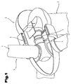
- Fig. 1 shows in an oblique view and partially cut a section of a wind turbine 1, as it is known in principle from the prior art.
- This wind turbine 1 comprises a tower 2, at the top of a nacelle 3, is arranged.
- a Rotomabe 4 is arranged, which carries at one end rotor blades 5, in particular rotatably. The other end is for generating electricity, a generator 6, which is designed in this case as a ring generator assigned.
- the rotor shaft 4 is via a bearing element. 7 rotatably mounted in the nacelle 3.
- the bearing element 7 is the so-called main bearing of the wind turbine 1.
- Fig. 1 it is in the wind turbine 1 is a gearless version, that is, between the rotor itself, that is, the rotor blades 5, and the generator 6, no transmission gear is present. It is a so-called slow runner.
- wind power plants are known from the prior art, which have a transmission gear between the rotor and the generator, often a planetary gear, so that the rotor of the generator runs faster than the rotor hub.
- the invention relates to the former, that is, the gearless type of wind turbines 1, although the invention can be applied in principle in wind turbines with transmission gear.
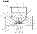
- the Fig. 2 to 5 show a first embodiment of the bearing element 7 according to the invention Fig. 2 a section of the wind turbine 1 in the field of Rotomabe 4 shown.
- the bearing element 7 is formed by a sliding bearing with two axially spaced sliding bearings 8.9 or includes these. With axial distance is meant the direction along the longitudinal central axis through the rotor hub 4.
- the bearing element 7 further comprises an inner ring element 10, and an outer ring element 11.
- the inner ring element 10 is designed in two parts with a first ring 12 and a second ring 13, wherein between the rings 12, 13, a spacer element 14 is arranged, so that the two rings 12, 13 are spaced apart in the axial direction.
- the plain bearings 8, 9 are arranged between these two ring elements 10, 11, wherein the outer ring member 11 is rotatable and the inner ring member 10 is arranged stationary, that is fixed.
- the outer ring element 11 is also connected via a corresponding fastening arrangement 15 with the rotor hub 4 or the rotor.
- a Ring groove 18 may be formed in an outer surface in which the inner ring member 10 is at least partially arranged, in particular fixed.
- the two slide bearings 8, 9 are preferably arranged in this embodiment in two different planes, which enclose an angle 19 with each other.
- the angle 19 may be selected from a range with a lower limit of 30 ° and an upper limit of 75 °, in particular from a range with a lower limit of 35 ° and an upper limit of 60 °. Due to the angular arrangement of the two slide bearings 8, 9 tilting moments can be better absorbed by the bearing element 7.
- the two sliding bearings 8, 9 after Fig. 2 formed by plain bearing pads 20 and include these plain bearing pads 20.
- a plurality of plain bearings pads 20 arranged so as to form the bearing surface.
- the number of plain bearing pads 20 per slide bearing 8, 9 is selected from a range with a lower limit of D / 10 and an upper limit of D / 2, where D denotes the maximum diameter of the inner ring element 10 in centimeters.
- D denotes the maximum diameter of the inner ring element 10 in centimeters.
- 50 such sliding bearing pads 20 can be distributed over the circumference.
- plain bearing pads 20 depends on the size of the circumference, so that a different number of plain bearing pads 20 can be arranged.
- These plain bearing pads 20 may, for example, have a length 21 in the circumferential direction of 122 mm and a width 22 perpendicular thereto of 194 mm.
- these plain bearing pads can have a size in the size of DIN A5 to DIN A4.
- the plain bearing pads 20 are preferably attached to the outer ring member 11.
- This can be provided according to an embodiment variant, as is made Fig. 4 it can be seen that in this outer ring member 20 on the sliding bearing pads 20 facing surface grooves 23 are arranged, in which the plain bearing pads 20 can be inserted.
- these grooves 23 have a cross-section widening from the surface in the direction of a groove base 24, in particular these grooves 23 are at least approximately dovetail-shaped or T-shaped in cross-section, with the slide-bearing pads 20 having a cross-sectional profile complementary thereto, ie one Enlarging cross section of a sliding surface 25 in the direction of a sliding bearing pad back 26.
- the cross-sectional widening can be formed on all side walls of the grooves 23 or only on individual ones of the side walls, for example only on the rear side wall.
- grooves 23 are provided in the corner areas with curves - preferably with the exception of the front corner areas where the plain bearing pads are inserted, as well as on Fig. 4 is apparent.
- the mating surface formed by the inner ring element 10, that is to say the rings 12, 13 in this embodiment variant, is formed in particular by steel, so that this ring element 10 can thus be formed from steel, just as the outer ring element 11
- the attachment of the sliding bearing pads 20 on the outer ring member 11, so that the plain bearing pads 20 are better protected during operation against slipping out of the grooves 23, can be done by various methods, for example, by welding, solder joints, clamping elements, etc.
- the attachment can be seen, via a releasable fastening element 27, in particular a screw.
- a releasable fastening element 27 in particular a screw.
- the fastening element 27 is preferably formed by a threaded screw, wherein the plain bearing pads 20 are secured by washers 28 from slipping out of the grooves 23 in the outer ring member 11.
- the plain bearing pads 20, as shown in Fig. 5 is shown in the region of the slide bearing pad back 26 at least partially in the width direction 22 opposite end portions 29, 30 at least approximately wedge-shaped (viewed in the direction of the length 21), wherein a wedge 31 for fixing the slide bearing pad 20 in the groove 23 of the outer ring member 11, for which purpose this groove 23 has a corresponding, opposite contour, and a further wedge 32 rests on the washers 28. It is thus achieved that the slide bearing pad 20 is pressed into the groove 23 of the outer ring member 11 by the inclination of the sliding bearing pads 20 and by screwing the fastening element 27.
- the fastening element 27 - at least approximately centrally viewed in the axial direction - arranged in the outer ring member 11 so that by a fastener 27 each two opposite plain bearing pads 20 of the two sliding bearings 8, 9 can be held and fixed.
- the plain bearing pads 20 preferably have a multi-layer structure, as is apparent from Fig. 3 If appropriate, further layers can be arranged between the support layer 33 and the sliding layer 34, for example a bearing metal layer and / or a bonding layer or a diffusion barrier layer.
- the sliding layer 34 is preferably executed interrupted at least in the surface area, so that a plurality, in particular two, sliding layer part surfaces 35 are formed. It has namely been found that a better load distribution can be achieved by the split sliding layer 34.
- Recesses 36 in particular grooves, can be provided between the sliding layer part surfaces 35, which can extend, for example, only over part of the layer thickness of the sliding layer 34 or over the entire layer thickness. These grooves 36 can be used in particular as ⁇ lzuurmuten.
- an end face 37 of at least the sliding layer 34 is at least partially provided with a rounding to in order to achieve a better oil intake in the region of the sliding layer 33, that is, the running surface of the slide bearing pads 20.
- this rounding extends in the region of at least one of the side walls of the grooves 23 in the outer ring member 11, wherein optionally both side region, that is, both end faces 37, which lie opposite each other and rest against the side walls of the groove, at least the sliding layer 34 with such Rounding can be provided so that the sliding layer 33 in plan view has a hyperbolic outer contour and thus a central region of the sliding layer 34 is further away from the side wall of the grooves 23 as a corner region.
- the surface of the slide bearing pads 20 should also be made rounded, that is, the surface of at least the sliding layer 34 is adjusted according to the rounding of the inner ring member 10.
- the sliding layer 34 consists of a relatively hard sliding bearing material having a hardness of at least 75 HV (0.001), in particular of at least 100 HV (0.001), at least on the sliding layer surface 35.
- the sliding layer may be formed of a material selected from a group comprising aluminum-base alloys, such as AlSn20Cu, AlZn4Si3, silver-based alloys or copper-base alloys, optionally with bismuth, bismuth base alloys, if appropriate.
- the sliding layer 34 can also be formed by a lubricating varnish, in which case the sliding layer 34 has a hardness between 25 HV (0.001) to 60 HV (0.001).
- polytetrafluoroethylene fluorine-containing resins such as perfluoroalkoxy copolymers, polyfluoroalkoxy-polytetrafluoroethylene copolymers, ethylene-tetrafluoroethylene, polychlorotrifluoroethylene, fluorinated ethylene-propylene copolymers, polyvinyl fluoride, polyvinylidene fluoride, alternating copolymers, random copolymers such as perfluoroethylene-propylene, polyester-imides, Bismaleimides, polyimide resins such as carborane imides, aromatic polyimide resins, hydrogen-free polyimide resins, polytriazo-pyromellithimides, polyamideimides, especially aromatic, polyaryletherimides, optionally modified with isocyanates, polyetherimides, optionally modified with isocyanates, epoxy resins, epoxy resin esters, phenolic resins, polyamide 6, polyamide 66 , Polyoxymethylene, Silicones,
- a lubricating varnish consisting in the dry state of 40 wt .-% to 45 wt .-% MoS2, 20 wt .-% to 25 wt .-% graphite and 30 wt .-% to 40 wt .-% polyamideimide, wherein optionally even hard particles, such as Oxides, nitrides or carbides, in the bonded coating in a proportion of a total of 20 wt .-% may be included, which replace a proportion of solid lubricants.
- hard particles such as Oxides, nitrides or carbides
- the support layer 33 may be formed, for example, by steel or a copper-based alloy, in particular with zinc, for example CuZn31Si, CuSnZn, an AlZn or a CuAl alloy.
- the Fig. 6 to 8 show another embodiment of the bearing element 7 for a wind turbine 1.
- the bearing element 7 consists of two axially spaced slide bearings 38, 39 which are arranged between an inner ring member 40 and an outer ring member 41.
- the inner ring member 40 is a part of a rotor hub 42 and the outer ring member 41 is part of a stator 43 of the wind turbine 1.
- the inner ring member 40 is rotatable and outer ring member 41 fixedly arranged.
- the two plain bearings 38, 39 are arranged in this embodiment in a plane, it being understood that it is of course possible that these two plain bearings 38, 39 are arranged in this embodiment in two mutually angular planes.
- these two plain bearings 38, 39 but relatively widely spaced from each other, wherein a distance 44 between the two plain bearings 38, 39, measured between the facing end faces in the circumferential direction of the plain bearings 38, 39, at least 40%, in particular at least 50%, one maximum circumferential length of the inner ring member 40th is.
- the two plain bearings 38, 39 are formed as slide bearing segments 45, as is known from the Fig. 7 and 8th it can be seen that over the circumference of the inner ring member 40 a plurality of sliding bearing segments 45 form a sliding bearing 38 and 39, respectively.
- a variety of methods and methods can be used, as already described above, wherein according to a preferred embodiment, the sliding bearing segments 45 are bevelled at end surfaces 46, 47 and between the sliding bearing segments 45 to the bias or attachment a wedge element 48 is arranged, as is out Fig. 9 it can be seen, via this wedge member 48, the sliding bearing segments 45 are pressed against the inner surface of the outer ring member 41.
- the plain bearing segments 45 are arranged at a distance from one another - viewed in the circumferential direction - due to the wedge elements 48 arranged therebetween.
- the possibility in the inner ring member 40 that is, on a surface facing the outer ring member of the inner ring member 40 and / or at one inner ring member 40 facing surface of the outer ring member 41 to provide a groove.
- the bearing element 7 according to the invention is preferably exclusively hydrodynamically operable, so that no hydrostatics is required as start-up support.
- exclusively hydrodynamic means in the sense of the invention that no oil pressure of more than 1 bar is maintained, so that only a minimum amount is supplied via the at least one groove and / or the at least one bore 51 of a sliding surface 52. So it's over These grooves 50 and bores 51 a targeted supply of oil per sliding bearing 45 possible.
- Both the plain bearing pads 20 and the plain bearing segments 45 may be designed not only as a radial sliding bearing, but also be provided on at least one parallel to the circumferential direction formed end face with a corresponding sliding layer material, so so an additional axial bearing on these slide bearing pads 20 and the plain bearing segments 45 is achieved.
- the replacement of the plain bearing segments 45 and the installation of these sliding bearing segments 45 in the bearing element 7 can be done by lateral removal from or lateral insertion into the bearing element 7 - viewed in the axial direction.
- the fastener 27 is released and optionally removed, as well as the spacer 14.
- these plain bearing pads 20 can each be pulled out obliquely downward from the grooves 23.
- the installation or replacement of these plain bearing pads 20 can be done in exactly the reverse order.
Landscapes
- Engineering & Computer Science (AREA)
- General Engineering & Computer Science (AREA)
- Mechanical Engineering (AREA)
- Life Sciences & Earth Sciences (AREA)
- Sustainable Development (AREA)
- Sustainable Energy (AREA)
- Chemical & Material Sciences (AREA)
- Combustion & Propulsion (AREA)
- Sliding-Contact Bearings (AREA)
- Wind Motors (AREA)
- Support Of The Bearing (AREA)
Priority Applications (2)
| Application Number | Priority Date | Filing Date | Title |
|---|---|---|---|
| EP16172461.2A EP3124811B1 (de) | 2010-04-14 | 2011-04-14 | Lagerelement |
| DK16172461.2T DK3124811T3 (da) | 2010-04-14 | 2011-04-14 | Lejeelement |
Applications Claiming Priority (2)
| Application Number | Priority Date | Filing Date | Title |
|---|---|---|---|
| AT0059910A AT509625B1 (de) | 2010-04-14 | 2010-04-14 | Lagerelement |
| PCT/AT2011/000182 WO2011127510A1 (de) | 2010-04-14 | 2011-04-14 | Lagerelement |
Related Child Applications (2)
| Application Number | Title | Priority Date | Filing Date |
|---|---|---|---|
| EP16172461.2A Division-Into EP3124811B1 (de) | 2010-04-14 | 2011-04-14 | Lagerelement |
| EP16172461.2A Division EP3124811B1 (de) | 2010-04-14 | 2011-04-14 | Lagerelement |
Publications (2)
| Publication Number | Publication Date |
|---|---|
| EP2558718A1 EP2558718A1 (de) | 2013-02-20 |
| EP2558718B1 true EP2558718B1 (de) | 2016-11-09 |
Family
ID=44115750
Family Applications (2)
| Application Number | Title | Priority Date | Filing Date |
|---|---|---|---|
| EP11722706.6A Active EP2558718B1 (de) | 2010-04-14 | 2011-04-14 | Lagerelement |
| EP16172461.2A Active EP3124811B1 (de) | 2010-04-14 | 2011-04-14 | Lagerelement |
Family Applications After (1)
| Application Number | Title | Priority Date | Filing Date |
|---|---|---|---|
| EP16172461.2A Active EP3124811B1 (de) | 2010-04-14 | 2011-04-14 | Lagerelement |
Country Status (7)
| Country | Link |
|---|---|
| US (1) | US9458880B2 (da) |
| EP (2) | EP2558718B1 (da) |
| KR (1) | KR101749286B1 (da) |
| CN (1) | CN102834611B (da) |
| AT (1) | AT509625B1 (da) |
| DK (2) | DK2558718T3 (da) |
| WO (1) | WO2011127510A1 (da) |
Cited By (2)
| Publication number | Priority date | Publication date | Assignee | Title |
|---|---|---|---|---|
| WO2020237276A1 (de) | 2019-05-29 | 2020-12-03 | Miba Gleitlager Austria Gmbh | Mehrschichtgleitlager und verfahren zum herstellen eines mehrschichtgleitlagers |
| WO2020237275A1 (de) | 2019-05-29 | 2020-12-03 | Miba Gleitlager Austria Gmbh | Verfahren zum herstellen eines mehrschichtgleitlagers und gleitlagerherstellvorrichtung |
Families Citing this family (46)
| Publication number | Priority date | Publication date | Assignee | Title |
|---|---|---|---|---|
| EP2568168A1 (en) | 2011-09-08 | 2013-03-13 | Siemens Aktiengesellschaft | Direct-drive wind turbine |
| EP2607694B1 (en) * | 2011-12-22 | 2015-08-12 | Siemens Aktiengesellschaft | Method for operating a wind turbine |
| EP2657519B1 (en) * | 2012-04-26 | 2015-06-17 | Siemens Aktiengesellschaft | Wind turbine |
| WO2013191163A1 (ja) | 2012-06-19 | 2013-12-27 | 富士電機株式会社 | 複合すべり軸受およびこの軸受けを用いた風力発電装置 |
| WO2014161607A1 (en) * | 2013-04-03 | 2014-10-09 | Aktiebolaget Skf | A hub and bearing system and a turbine comprising the hub and bearing system |
| DE102013211710C5 (de) * | 2013-06-20 | 2016-11-10 | Siemens Aktiengesellschaft | Windkraftanlage mit einem Gleitlager |
| DK179046B1 (en) * | 2016-02-25 | 2017-09-18 | Envision Energy Denmark Aps | Wind turbine comprising a moment bearing |
| DE102016209206A1 (de) * | 2016-05-27 | 2017-12-14 | Wobben Properties Gmbh | Windenergieanlage |
| DE102016210039A1 (de) | 2016-06-07 | 2017-12-07 | Wobben Properties Gmbh | Windenergieanlagen-Drehverbindung, Rotorblatt und Windenergieanlage mit selbiger |
| DE102016113718B3 (de) * | 2016-07-26 | 2018-02-01 | Gleitlagertechnik Weissbacher Gmbh | Gleitgelagerte doppelwandige Rotornabe für eine Windenergieanlage |
| AT519288B1 (de) | 2016-10-21 | 2018-07-15 | Miba Gleitlager Austria Gmbh | Lagerelement |
| US10385830B2 (en) | 2017-07-14 | 2019-08-20 | General Electric Company | Compound main bearing arrangement for a wind turbine |
| DE102017006957A1 (de) | 2017-07-25 | 2019-01-31 | Rheinisch-Westfälische Technische Hochschule (Rwth) Aachen | Gleitlagervorrichtung |
| DK3460272T3 (da) * | 2017-09-20 | 2020-06-02 | Siemens Gamesa Renewable Energy As | Fremgangsmåde til udskiftning af en lejekomponent og en værktøjsindretning til udskiftning af en lejekomponent |
| US10677290B2 (en) * | 2017-10-13 | 2020-06-09 | General Electric Company | Wind turbine pitch bearing with line contact rolling elements |
| EP3810359A1 (en) | 2018-06-25 | 2021-04-28 | General Electric Company | Additively manufactured journal bearing for a wind turbine gearbox |
| EP3604839A1 (de) * | 2018-08-03 | 2020-02-05 | Ondal Medical Systems GmbH | Lageranordnung |
| DE102018120806A1 (de) | 2018-08-27 | 2020-02-27 | Renk Aktiengesellschaft | Lageranordnung eines Rotors einer Windkraftanlage |
| DE102018120810A1 (de) * | 2018-08-27 | 2020-02-27 | Renk Aktiengesellschaft | Lageranordnung eines Rotors einer Windkraftanlage und Windkraftanlage |
| PL3660302T3 (pl) | 2018-11-29 | 2023-03-27 | General Electric Renovables España S.L. | System odchylania dla turbiny wiatrowej |
| AT521775B1 (de) | 2018-12-13 | 2020-06-15 | Miba Gleitlager Austria Gmbh | Planetengetriebe für eine Windkraftanlage |
| AT521953B1 (de) * | 2018-12-13 | 2020-07-15 | Miba Gleitlager Austria Gmbh | Gondel für eine Windkraftanlage |
| AT521882B1 (de) | 2018-12-13 | 2021-05-15 | Miba Gleitlager Austria Gmbh | Gleitlager, insbesondere für ein Getriebe einer Windkraftanlage |
| AT521940B1 (de) * | 2018-12-13 | 2020-10-15 | Miba Gleitlager Austria Gmbh | Verfahren zum Wechseln eines Gleitlagerelementes einer Rotorlagerung einer Windkraftanlage, sowie Gondel für eine Windkraftanlage |
| AT521884B1 (de) * | 2018-12-13 | 2020-10-15 | Miba Gleitlager Austria Gmbh | Verfahren zum Wechseln eines Gleitlagerelementes einer Rotorlagerung einer Windkraftanlage, sowie Gondel für eine Windkraftanlage |
| AT521885B1 (de) | 2018-12-13 | 2020-09-15 | Miba Gleitlager Austria Gmbh | Gondel für eine Windkraftanlage |
| AT521687B1 (de) * | 2018-12-13 | 2020-04-15 | Miba Gleitlager Austria Gmbh | Gondel für eine Windkraftanlage |
| AT522164B1 (de) | 2019-03-07 | 2020-09-15 | Miba Gleitlager Austria Gmbh | Gleitlagerung |
| AT522155B1 (de) * | 2019-03-07 | 2020-09-15 | Miba Gleitlager Austria Gmbh | Gleitlagerung |
| US11174895B2 (en) | 2019-04-30 | 2021-11-16 | General Electric Company | Bearing for a wind turbine drivetrain having an elastomer support |
| US11073137B2 (en) | 2019-07-02 | 2021-07-27 | General Electric Company | Journal bearing housing and shaft for a wind turbine drivetrain having corresponding deformation |
| DE102019131245A1 (de) | 2019-11-19 | 2021-05-20 | Zollern BHW Gleitlagertechnologie GmbH & Co. KG | Lageranordnung und Verfahren zum Montieren einer solchen |
| EP4311952A3 (en) * | 2020-01-08 | 2024-05-22 | Vestas Wind Systems A/S | Main bearing housing of a wind turbine |
| DE102020108248B3 (de) | 2020-03-25 | 2021-09-02 | Renk Gmbh | Vorrichtung zum Montieren und Demontieren eines Lagersegments einer Lageranordnung für einen Rotor einer Windkraftanlage |
| EP3904709A1 (en) * | 2020-04-28 | 2021-11-03 | Siemens Gamesa Renewable Energy A/S | Fluid film bearing, especially for a rotor hub in a wind turbine |
| DK3904677T3 (da) * | 2020-04-28 | 2023-11-20 | Siemens Gamesa Renewable Energy As | Fluidfilmleje og vindmølle |
| DE102020112765A1 (de) * | 2020-05-12 | 2021-11-18 | Miba Gleitlager Austria Gmbh | Rotorhauptlagerung einer Gondel für eine Windkraftanlage |
| US11773963B2 (en) | 2020-06-29 | 2023-10-03 | General Electric Company | Wind turbine gearbox carrier with integrated pin shafts and method of manufacturing same |
| DE102020126284A1 (de) | 2020-10-07 | 2022-04-07 | Miba Gleitlager Austria Gmbh | Gleitlagerung, sowie eine mit der Gleitlagerung ausgestattete Gondel für eine Windkraftanlage und eine Windkraftanlage |
| DE112021006222A5 (de) | 2020-11-30 | 2023-10-12 | Miba Gleitlager Austria Gmbh | Gleitlagerung, sowie eine mit der gleitlagerung ausgestattete gondel für eine windkraftanlage |
| WO2022109634A1 (de) | 2020-11-30 | 2022-06-02 | Miba Gleitlager Austria Gmbh | Verfahren zum wechseln von an einer rotorwelle einer rotorlagerung einer windkraftanlage angeordneten gleitlagerpads |
| WO2022109649A1 (de) | 2020-11-30 | 2022-06-02 | Miba Gleitlager Austria Gmbh | Gleitlagerpad und eine gleitlagerung, sowie eine mit der gleitlagerung ausgestattete gondel für eine windkraftanlage |
| AT524318B1 (de) | 2020-11-30 | 2022-05-15 | Miba Gleitlager Austria Gmbh | Gleitlagerung, sowie eine mit der Gleitlagerung ausgestattete Gondel für eine Windkraftanlage |
| WO2022109635A1 (de) | 2020-11-30 | 2022-06-02 | Miba Gleitlager Austria Gmbh | Verfahren zum zusammenbau einer rotorlagerung einer windkraftanlage |
| AT524667B1 (de) | 2021-07-20 | 2022-08-15 | Miba Gleitlager Austria Gmbh | Verfahren sowie Montagevorrichtung zum Zusammenbau einer Rotorlagerung |
| EP4296508A1 (en) * | 2022-06-20 | 2023-12-27 | Siemens Gamesa Renewable Energy A/S | Fluid bearing comprising a brake assembly |
Citations (2)
| Publication number | Priority date | Publication date | Assignee | Title |
|---|---|---|---|---|
| US1593251A (en) * | 1925-07-28 | 1926-07-20 | Flintermann Gerhard | Journal bearing |
| JPH09112564A (ja) * | 1995-10-17 | 1997-05-02 | Toshiba Corp | 回転電機のすべり軸受 |
Family Cites Families (38)
| Publication number | Priority date | Publication date | Assignee | Title |
|---|---|---|---|---|
| US714114A (en) * | 1902-03-24 | 1902-11-18 | August J Weil | Journal-bearing. |
| US2099661A (en) * | 1934-04-12 | 1937-11-16 | Baldwin Southwark Corp | Strip bearing |
| US2276143A (en) * | 1935-12-31 | 1942-03-10 | Ironsides Company | Bearing |
| US2393017A (en) * | 1943-09-15 | 1946-01-15 | Westinghouse Electric Corp | Bearing assembly |
| US3497278A (en) * | 1968-02-26 | 1970-02-24 | Goodrich Co B F | Bearing assembly |
| US3826547A (en) * | 1973-04-27 | 1974-07-30 | Johnson Rubber Co | Water lubricated rubber bearing |
| US4012085A (en) * | 1975-10-16 | 1977-03-15 | Dresser Industries, Inc. | Shaft support means |
| US4082379A (en) * | 1976-10-19 | 1978-04-04 | Swearingen Judson S | Bearing assembly |
| DE3332357C1 (de) * | 1983-09-08 | 1985-04-04 | Klein, Schanzlin & Becker Ag, 6710 Frankenthal | Hydrostatisch-hydrodynamisches Hybrid-Mehrgleitflaechenradiallager |
| US4663810A (en) * | 1985-01-07 | 1987-05-12 | The B. F. Goodrich Company | Method for fabricating an elastomeric bearing assembly |
| US4735982A (en) * | 1986-07-25 | 1988-04-05 | The B. F. Goodrich Company | Thermoplastic-rubber polymer alloys and method for producing the same |
| DE3625840A1 (de) * | 1986-07-30 | 1988-02-11 | Scholz Hans Ulrich | Windkraftanlage |
| US5518318A (en) * | 1988-04-15 | 1996-05-21 | The Bf Goodrich Company | Bearing assembly |
| GB8915254D0 (en) * | 1989-07-03 | 1989-08-23 | T & N Technology Ltd | Bearings |
| US6238093B1 (en) * | 1997-04-17 | 2001-05-29 | Duramax Marine, Llc | Partial arc bearing assembly and method of making the same |
| JPH10299780A (ja) * | 1997-04-29 | 1998-11-10 | Daido Metal Co Ltd | すべり軸受 |
| JP2001132754A (ja) * | 1999-11-04 | 2001-05-18 | Daido Metal Co Ltd | 多層すべり軸受 |
| DE19962978C1 (de) * | 1999-12-24 | 2001-08-30 | Aloys Wobben | Windenergieanlage mit einem turmgestützten Maschinenkopf |
| JP3782918B2 (ja) * | 2000-03-28 | 2006-06-07 | Ntn株式会社 | 動圧型軸受ユニット |
| DE10043593B4 (de) | 2000-09-01 | 2014-01-09 | Renk Ag | Getriebe für Windgeneratoren |
| DE10043936C2 (de) | 2000-09-07 | 2003-09-04 | Skf Gmbh | Gleitlager |
| DE10102255A1 (de) | 2001-01-19 | 2002-08-01 | Aloys Wobben | Windenergieanlage mit einer Hohlwelle für Rotornabe und Generator |
| JP4121947B2 (ja) * | 2001-06-06 | 2008-07-23 | デラウエア キャピタル フォーメイション、インコーポレイテッド | ジャーナル軸受装置 |
| DE20208133U1 (de) * | 2002-05-24 | 2003-10-02 | Skf Ab | Gleitlager zur axialen und radialen Lagerung |
| DE10239366A1 (de) * | 2002-08-28 | 2004-03-11 | Klinger, Friedrich, Prof. Dr.-Ing. | Windenergieanlage |
| DE10255745A1 (de) | 2002-11-28 | 2004-06-17 | Jörck, Hartmut | Direkt angetriebene Windenergieanlage mit im Generator integriertem Lager |
| AT502546B1 (de) * | 2005-09-16 | 2007-10-15 | Miba Gleitlager Gmbh | Lagerelement |
| DE102005051912A1 (de) | 2005-10-29 | 2007-05-03 | Ab Skf | Anordnung |
| KR100695012B1 (ko) * | 2006-03-24 | 2007-03-14 | 유니슨 주식회사 | 풍력 발전기 |
| EP2079928B1 (en) * | 2006-11-03 | 2013-11-27 | Vestas Wind Systems A/S | A yawing system for a wind turbine |
| DE102007008758A1 (de) * | 2007-02-22 | 2008-08-28 | Schuler Pressen Gmbh & Co. Kg | Getriebe-Nabeneinheit für eine Windkraftanlage |
| US7675211B2 (en) * | 2007-03-06 | 2010-03-09 | General Electric Company | Method of assembling a rotor shaft assembly |
| DE102007042770A1 (de) * | 2007-09-07 | 2009-03-12 | Schaeffler Kg | Rotorlagerung für eine Windenergieanlage |
| US8198749B2 (en) * | 2007-10-23 | 2012-06-12 | Mitsubishi Heavy Industries, Ltd. | Wind turbine generator |
| DK2108832T3 (da) * | 2008-04-10 | 2016-02-29 | Siemens Ag | Generator og vindmølle |
| WO2011003482A2 (en) * | 2009-07-10 | 2011-01-13 | Siemens Aktiengesellschaft | Wind turbine main bearing |
| US20110057451A1 (en) * | 2009-09-30 | 2011-03-10 | Matthias Alfons Volmer | Yaw bearing assembly for use with a wind turbine and a method for braking using the same |
| US8172531B2 (en) * | 2011-01-10 | 2012-05-08 | Vestas Wind Systems A/S | Plain bearing for a wind turbine blade and method of operating a wind turbine having such a plain bearing |
-
2010
- 2010-04-14 AT AT0059910A patent/AT509625B1/de not_active IP Right Cessation
-
2011
- 2011-04-14 WO PCT/AT2011/000182 patent/WO2011127510A1/de active Application Filing
- 2011-04-14 DK DK11722706.6T patent/DK2558718T3/da active
- 2011-04-14 EP EP11722706.6A patent/EP2558718B1/de active Active
- 2011-04-14 EP EP16172461.2A patent/EP3124811B1/de active Active
- 2011-04-14 US US13/640,613 patent/US9458880B2/en active Active
- 2011-04-14 CN CN201180018616.6A patent/CN102834611B/zh active Active
- 2011-04-14 DK DK16172461.2T patent/DK3124811T3/da active
- 2011-04-14 KR KR1020127029761A patent/KR101749286B1/ko active IP Right Grant
Patent Citations (2)
| Publication number | Priority date | Publication date | Assignee | Title |
|---|---|---|---|---|
| US1593251A (en) * | 1925-07-28 | 1926-07-20 | Flintermann Gerhard | Journal bearing |
| JPH09112564A (ja) * | 1995-10-17 | 1997-05-02 | Toshiba Corp | 回転電機のすべり軸受 |
Cited By (4)
| Publication number | Priority date | Publication date | Assignee | Title |
|---|---|---|---|---|
| WO2020237276A1 (de) | 2019-05-29 | 2020-12-03 | Miba Gleitlager Austria Gmbh | Mehrschichtgleitlager und verfahren zum herstellen eines mehrschichtgleitlagers |
| WO2020237275A1 (de) | 2019-05-29 | 2020-12-03 | Miba Gleitlager Austria Gmbh | Verfahren zum herstellen eines mehrschichtgleitlagers und gleitlagerherstellvorrichtung |
| EP4219970A1 (de) | 2019-05-29 | 2023-08-02 | Miba Gleitlager Austria GmbH | Verfahren zum herstellen eines mehrschichtgleitlagers und gleitlagerherstellvorrichtung |
| EP4324574A1 (de) | 2019-05-29 | 2024-02-21 | Miba Gleitlager Austria GmbH | Mehrschichtgleitlager und verfahren zum herstellen eines mehrschichtgleitlagers |
Also Published As
| Publication number | Publication date |
|---|---|
| WO2011127510A1 (de) | 2011-10-20 |
| AT509625A9 (de) | 2012-01-15 |
| DK2558718T3 (da) | 2017-02-20 |
| AT509625B1 (de) | 2012-02-15 |
| US9458880B2 (en) | 2016-10-04 |
| CN102834611A (zh) | 2012-12-19 |
| KR20130093498A (ko) | 2013-08-22 |
| AT509625A1 (de) | 2011-10-15 |
| EP2558718A1 (de) | 2013-02-20 |
| US20130071246A1 (en) | 2013-03-21 |
| EP3124811A1 (de) | 2017-02-01 |
| DK3124811T3 (da) | 2022-03-14 |
| CN102834611B (zh) | 2015-11-25 |
| EP3124811B1 (de) | 2021-12-08 |
| KR101749286B1 (ko) | 2017-06-20 |
Similar Documents
| Publication | Publication Date | Title |
|---|---|---|
| EP2558718B1 (de) | Lagerelement | |
| AT509624B1 (de) | Windkraftanlage | |
| AT512436B1 (de) | Windkraftanlage | |
| AT513507B1 (de) | Gleitlagerpaket | |
| EP2787226B1 (de) | Hydrodynamisches Radialgleitlager für große Turbosätze | |
| EP2694831B1 (de) | Drehverbindung für unterwasserbetrieb sowie damit ausgerüstete anlage zur energiegewinnung aus wasserkraft | |
| EP3350463B1 (de) | Drehlager | |
| EP2387664A2 (de) | Windkraftanlage | |
| EP2676042B1 (de) | Axial-radialwälzlager, insbesondere für die lagerung von rotorblättern an einer windkraftanlage | |
| WO2012065840A1 (de) | Baugruppe als lageranordnung zur drehenden lagerung von maschinen- und anlagenteilen | |
| DE102010054318A1 (de) | Rotorlagerung einer Windkraftanlage | |
| WO2018189143A1 (de) | Lageranordnung zur lagerung eines rotorblatts einer windenergieanlage | |
| WO2015150159A1 (de) | Wälzlageranordnung und windkraftanlage | |
| EP3589839A1 (de) | Verstelleinheit für eine azimutverstellung und/oder für eine pitchverstellung einer windenergieanlage und verfahren | |
| EP3894716B1 (de) | Gondel für eine windkraftanlage | |
| AT507397A1 (de) | Nabenwellen-gleitlager | |
| DE1425933A1 (de) | Einreihige Kugeldrehverbindung | |
| WO2015144805A1 (de) | Lageranordnung zur drehbaren lagerung eines turbinenblattes an einer turbinennabe | |
| EP3645901B1 (de) | Windenergieanlagen-drehverbindung, und windenergieanlage mit selbiger | |
| WO2018202330A1 (de) | Stützlagerung, insbesondere hauptlagerung für eine windenergieanlage, und windenergieanlage mit einer solchen stützlagerung | |
| EP3555468A1 (de) | WINDENERGIEANLAGE MIT GROßWÄLZLAGER UND VERFAHREN ZU DESSEN MONTAGE | |
| DE102010054321A1 (de) | Rotorlagerung einer Windkraftanlage |
Legal Events
| Date | Code | Title | Description |
|---|---|---|---|
| PUAI | Public reference made under article 153(3) epc to a published international application that has entered the european phase |
Free format text: ORIGINAL CODE: 0009012 |
|
| 17P | Request for examination filed |
Effective date: 20121113 |
|
| AK | Designated contracting states |
Kind code of ref document: A1 Designated state(s): AL AT BE BG CH CY CZ DE DK EE ES FI FR GB GR HR HU IE IS IT LI LT LU LV MC MK MT NL NO PL PT RO RS SE SI SK SM TR |
|
| DAX | Request for extension of the european patent (deleted) | ||
| 17Q | First examination report despatched |
Effective date: 20130904 |
|
| RAP1 | Party data changed (applicant data changed or rights of an application transferred) |
Owner name: MIBA GLEITLAGER AUSTRIA GMBH |
|
| GRAP | Despatch of communication of intention to grant a patent |
Free format text: ORIGINAL CODE: EPIDOSNIGR1 |
|
| RIC1 | Information provided on ipc code assigned before grant |
Ipc: F16C 17/10 20060101AFI20160304BHEP |
|
| INTG | Intention to grant announced |
Effective date: 20160321 |
|
| GRAS | Grant fee paid |
Free format text: ORIGINAL CODE: EPIDOSNIGR3 |
|
| GRAJ | Information related to disapproval of communication of intention to grant by the applicant or resumption of examination proceedings by the epo deleted |
Free format text: ORIGINAL CODE: EPIDOSDIGR1 |
|
| GRAL | Information related to payment of fee for publishing/printing deleted |
Free format text: ORIGINAL CODE: EPIDOSDIGR3 |
|
| REG | Reference to a national code |
Ref country code: DE Ref legal event code: R079 Ref document number: 502011011101 Country of ref document: DE Free format text: PREVIOUS MAIN CLASS: F03D0011000000 Ipc: F03D0080700000 |
|
| INTC | Intention to grant announced (deleted) | ||
| RIC1 | Information provided on ipc code assigned before grant |
Ipc: F16C 17/10 20060101ALI20160810BHEP Ipc: F03D 80/70 20160101AFI20160810BHEP |
|
| GRAP | Despatch of communication of intention to grant a patent |
Free format text: ORIGINAL CODE: EPIDOSNIGR1 |
|
| GRAA | (expected) grant |
Free format text: ORIGINAL CODE: 0009210 |
|
| INTG | Intention to grant announced |
Effective date: 20160916 |
|
| AK | Designated contracting states |
Kind code of ref document: B1 Designated state(s): AL AT BE BG CH CY CZ DE DK EE ES FI FR GB GR HR HU IE IS IT LI LT LU LV MC MK MT NL NO PL PT RO RS SE SI SK SM TR |
|
| REG | Reference to a national code |
Ref country code: GB Ref legal event code: FG4D Free format text: NOT ENGLISH |
|
| REG | Reference to a national code |
Ref country code: AT Ref legal event code: REF Ref document number: 844177 Country of ref document: AT Kind code of ref document: T Effective date: 20161115 Ref country code: CH Ref legal event code: EP |
|
| REG | Reference to a national code |
Ref country code: IE Ref legal event code: FG4D Free format text: LANGUAGE OF EP DOCUMENT: GERMAN |
|
| REG | Reference to a national code |
Ref country code: DE Ref legal event code: R096 Ref document number: 502011011101 Country of ref document: DE |
|
| REG | Reference to a national code |
Ref country code: DK Ref legal event code: T3 Effective date: 20170214 |
|
| PG25 | Lapsed in a contracting state [announced via postgrant information from national office to epo] |
Ref country code: LV Free format text: LAPSE BECAUSE OF FAILURE TO SUBMIT A TRANSLATION OF THE DESCRIPTION OR TO PAY THE FEE WITHIN THE PRESCRIBED TIME-LIMIT Effective date: 20161109 |
|
| REG | Reference to a national code |
Ref country code: SE Ref legal event code: TRGR |
|
| REG | Reference to a national code |
Ref country code: LT Ref legal event code: MG4D |
|
| REG | Reference to a national code |
Ref country code: NL Ref legal event code: MP Effective date: 20161109 |
|
| PG25 | Lapsed in a contracting state [announced via postgrant information from national office to epo] |
Ref country code: NO Free format text: LAPSE BECAUSE OF FAILURE TO SUBMIT A TRANSLATION OF THE DESCRIPTION OR TO PAY THE FEE WITHIN THE PRESCRIBED TIME-LIMIT Effective date: 20170209 Ref country code: NL Free format text: LAPSE BECAUSE OF FAILURE TO SUBMIT A TRANSLATION OF THE DESCRIPTION OR TO PAY THE FEE WITHIN THE PRESCRIBED TIME-LIMIT Effective date: 20161109 Ref country code: LT Free format text: LAPSE BECAUSE OF FAILURE TO SUBMIT A TRANSLATION OF THE DESCRIPTION OR TO PAY THE FEE WITHIN THE PRESCRIBED TIME-LIMIT Effective date: 20161109 Ref country code: GR Free format text: LAPSE BECAUSE OF FAILURE TO SUBMIT A TRANSLATION OF THE DESCRIPTION OR TO PAY THE FEE WITHIN THE PRESCRIBED TIME-LIMIT Effective date: 20170210 |
|
| PG25 | Lapsed in a contracting state [announced via postgrant information from national office to epo] |
Ref country code: PT Free format text: LAPSE BECAUSE OF FAILURE TO SUBMIT A TRANSLATION OF THE DESCRIPTION OR TO PAY THE FEE WITHIN THE PRESCRIBED TIME-LIMIT Effective date: 20170309 Ref country code: HR Free format text: LAPSE BECAUSE OF FAILURE TO SUBMIT A TRANSLATION OF THE DESCRIPTION OR TO PAY THE FEE WITHIN THE PRESCRIBED TIME-LIMIT Effective date: 20161109 Ref country code: PL Free format text: LAPSE BECAUSE OF FAILURE TO SUBMIT A TRANSLATION OF THE DESCRIPTION OR TO PAY THE FEE WITHIN THE PRESCRIBED TIME-LIMIT Effective date: 20161109 Ref country code: ES Free format text: LAPSE BECAUSE OF FAILURE TO SUBMIT A TRANSLATION OF THE DESCRIPTION OR TO PAY THE FEE WITHIN THE PRESCRIBED TIME-LIMIT Effective date: 20161109 Ref country code: RS Free format text: LAPSE BECAUSE OF FAILURE TO SUBMIT A TRANSLATION OF THE DESCRIPTION OR TO PAY THE FEE WITHIN THE PRESCRIBED TIME-LIMIT Effective date: 20161109 Ref country code: IS Free format text: LAPSE BECAUSE OF FAILURE TO SUBMIT A TRANSLATION OF THE DESCRIPTION OR TO PAY THE FEE WITHIN THE PRESCRIBED TIME-LIMIT Effective date: 20170309 |
|
| PG25 | Lapsed in a contracting state [announced via postgrant information from national office to epo] |
Ref country code: EE Free format text: LAPSE BECAUSE OF FAILURE TO SUBMIT A TRANSLATION OF THE DESCRIPTION OR TO PAY THE FEE WITHIN THE PRESCRIBED TIME-LIMIT Effective date: 20161109 Ref country code: SK Free format text: LAPSE BECAUSE OF FAILURE TO SUBMIT A TRANSLATION OF THE DESCRIPTION OR TO PAY THE FEE WITHIN THE PRESCRIBED TIME-LIMIT Effective date: 20161109 Ref country code: CZ Free format text: LAPSE BECAUSE OF FAILURE TO SUBMIT A TRANSLATION OF THE DESCRIPTION OR TO PAY THE FEE WITHIN THE PRESCRIBED TIME-LIMIT Effective date: 20161109 Ref country code: RO Free format text: LAPSE BECAUSE OF FAILURE TO SUBMIT A TRANSLATION OF THE DESCRIPTION OR TO PAY THE FEE WITHIN THE PRESCRIBED TIME-LIMIT Effective date: 20161109 |
|
| REG | Reference to a national code |
Ref country code: DE Ref legal event code: R097 Ref document number: 502011011101 Country of ref document: DE |
|
| PG25 | Lapsed in a contracting state [announced via postgrant information from national office to epo] |
Ref country code: SM Free format text: LAPSE BECAUSE OF FAILURE TO SUBMIT A TRANSLATION OF THE DESCRIPTION OR TO PAY THE FEE WITHIN THE PRESCRIBED TIME-LIMIT Effective date: 20161109 Ref country code: BG Free format text: LAPSE BECAUSE OF FAILURE TO SUBMIT A TRANSLATION OF THE DESCRIPTION OR TO PAY THE FEE WITHIN THE PRESCRIBED TIME-LIMIT Effective date: 20170209 Ref country code: IT Free format text: LAPSE BECAUSE OF FAILURE TO SUBMIT A TRANSLATION OF THE DESCRIPTION OR TO PAY THE FEE WITHIN THE PRESCRIBED TIME-LIMIT Effective date: 20161109 |
|
| PLBE | No opposition filed within time limit |
Free format text: ORIGINAL CODE: 0009261 |
|
| STAA | Information on the status of an ep patent application or granted ep patent |
Free format text: STATUS: NO OPPOSITION FILED WITHIN TIME LIMIT |
|
| 26N | No opposition filed |
Effective date: 20170810 |
|
| PG25 | Lapsed in a contracting state [announced via postgrant information from national office to epo] |
Ref country code: SI Free format text: LAPSE BECAUSE OF FAILURE TO SUBMIT A TRANSLATION OF THE DESCRIPTION OR TO PAY THE FEE WITHIN THE PRESCRIBED TIME-LIMIT Effective date: 20161109 |
|
| REG | Reference to a national code |
Ref country code: CH Ref legal event code: PL |
|
| GBPC | Gb: european patent ceased through non-payment of renewal fee |
Effective date: 20170414 |
|
| REG | Reference to a national code |
Ref country code: IE Ref legal event code: MM4A |
|
| REG | Reference to a national code |
Ref country code: FR Ref legal event code: ST Effective date: 20171229 |
|
| PG25 | Lapsed in a contracting state [announced via postgrant information from national office to epo] |
Ref country code: FR Free format text: LAPSE BECAUSE OF NON-PAYMENT OF DUE FEES Effective date: 20170502 Ref country code: MC Free format text: LAPSE BECAUSE OF FAILURE TO SUBMIT A TRANSLATION OF THE DESCRIPTION OR TO PAY THE FEE WITHIN THE PRESCRIBED TIME-LIMIT Effective date: 20161109 |
|
| PG25 | Lapsed in a contracting state [announced via postgrant information from national office to epo] |
Ref country code: LI Free format text: LAPSE BECAUSE OF NON-PAYMENT OF DUE FEES Effective date: 20170430 Ref country code: CH Free format text: LAPSE BECAUSE OF NON-PAYMENT OF DUE FEES Effective date: 20170430 Ref country code: GB Free format text: LAPSE BECAUSE OF NON-PAYMENT OF DUE FEES Effective date: 20170414 Ref country code: LU Free format text: LAPSE BECAUSE OF NON-PAYMENT OF DUE FEES Effective date: 20170414 |
|
| PG25 | Lapsed in a contracting state [announced via postgrant information from national office to epo] |
Ref country code: IE Free format text: LAPSE BECAUSE OF NON-PAYMENT OF DUE FEES Effective date: 20170414 |
|
| REG | Reference to a national code |
Ref country code: AT Ref legal event code: MM01 Ref document number: 844177 Country of ref document: AT Kind code of ref document: T Effective date: 20170414 |
|
| REG | Reference to a national code |
Ref country code: DE Ref legal event code: R082 Ref document number: 502011011101 Country of ref document: DE Representative=s name: ABP BURGER RECHTSANWALTSGESELLSCHAFT MBH, DE |
|
| PG25 | Lapsed in a contracting state [announced via postgrant information from national office to epo] |
Ref country code: AT Free format text: LAPSE BECAUSE OF NON-PAYMENT OF DUE FEES Effective date: 20170414 |
|
| PG25 | Lapsed in a contracting state [announced via postgrant information from national office to epo] |
Ref country code: MT Free format text: LAPSE BECAUSE OF FAILURE TO SUBMIT A TRANSLATION OF THE DESCRIPTION OR TO PAY THE FEE WITHIN THE PRESCRIBED TIME-LIMIT Effective date: 20161109 |
|
| PG25 | Lapsed in a contracting state [announced via postgrant information from national office to epo] |
Ref country code: HU Free format text: LAPSE BECAUSE OF FAILURE TO SUBMIT A TRANSLATION OF THE DESCRIPTION OR TO PAY THE FEE WITHIN THE PRESCRIBED TIME-LIMIT; INVALID AB INITIO Effective date: 20110414 |
|
| PG25 | Lapsed in a contracting state [announced via postgrant information from national office to epo] |
Ref country code: CY Free format text: LAPSE BECAUSE OF NON-PAYMENT OF DUE FEES Effective date: 20161109 |
|
| PG25 | Lapsed in a contracting state [announced via postgrant information from national office to epo] |
Ref country code: MK Free format text: LAPSE BECAUSE OF FAILURE TO SUBMIT A TRANSLATION OF THE DESCRIPTION OR TO PAY THE FEE WITHIN THE PRESCRIBED TIME-LIMIT Effective date: 20161109 |
|
| PG25 | Lapsed in a contracting state [announced via postgrant information from national office to epo] |
Ref country code: TR Free format text: LAPSE BECAUSE OF FAILURE TO SUBMIT A TRANSLATION OF THE DESCRIPTION OR TO PAY THE FEE WITHIN THE PRESCRIBED TIME-LIMIT Effective date: 20161109 |
|
| PG25 | Lapsed in a contracting state [announced via postgrant information from national office to epo] |
Ref country code: AL Free format text: LAPSE BECAUSE OF FAILURE TO SUBMIT A TRANSLATION OF THE DESCRIPTION OR TO PAY THE FEE WITHIN THE PRESCRIBED TIME-LIMIT Effective date: 20161109 |
|
| P01 | Opt-out of the competence of the unified patent court (upc) registered |
Effective date: 20230527 |
|
| PGFP | Annual fee paid to national office [announced via postgrant information from national office to epo] |
Ref country code: DK Payment date: 20230404 Year of fee payment: 13 Ref country code: DE Payment date: 20230411 Year of fee payment: 13 |
|
| PGFP | Annual fee paid to national office [announced via postgrant information from national office to epo] |
Ref country code: SE Payment date: 20230403 Year of fee payment: 13 Ref country code: FI Payment date: 20230406 Year of fee payment: 13 |
|
| PGFP | Annual fee paid to national office [announced via postgrant information from national office to epo] |
Ref country code: BE Payment date: 20230404 Year of fee payment: 13 |