EP2558394B2 - Aufzugsystem - Google Patents
Aufzugsystem Download PDFInfo
- Publication number
- EP2558394B2 EP2558394B2 EP11768498.5A EP11768498A EP2558394B2 EP 2558394 B2 EP2558394 B2 EP 2558394B2 EP 11768498 A EP11768498 A EP 11768498A EP 2558394 B2 EP2558394 B2 EP 2558394B2
- Authority
- EP
- European Patent Office
- Prior art keywords
- elevator
- elevator car
- acceleration
- deceleration
- loading
- Prior art date
- Legal status (The legal status is an assumption and is not a legal conclusion. Google has not performed a legal analysis and makes no representation as to the accuracy of the status listed.)
- Active
Links
Images

Classifications
-
- B—PERFORMING OPERATIONS; TRANSPORTING
- B66—HOISTING; LIFTING; HAULING
- B66B—ELEVATORS; ESCALATORS OR MOVING WALKWAYS
- B66B1/00—Control systems of elevators in general
- B66B1/24—Control systems with regulation, i.e. with retroactive action, for influencing travelling speed, acceleration, or deceleration
- B66B1/28—Control systems with regulation, i.e. with retroactive action, for influencing travelling speed, acceleration, or deceleration electrical
- B66B1/30—Control systems with regulation, i.e. with retroactive action, for influencing travelling speed, acceleration, or deceleration electrical effective on driving gear, e.g. acting on power electronics, on inverter or rectifier controlled motor
- B66B1/304—Control systems with regulation, i.e. with retroactive action, for influencing travelling speed, acceleration, or deceleration electrical effective on driving gear, e.g. acting on power electronics, on inverter or rectifier controlled motor with starting torque control
Definitions
- the invention relates to solutions for preventing the overloading of a motor drive of an elevator system.
- An elevator system comprises a motor drive for moving an elevator car.
- the motor drive usually comprises a hoisting machine of the elevator and also a power supply apparatus, such as a frequency converter, of the hoisting machine.
- the elevator car is moved in the elevator hoistway e.g. with suspension ropes traveling via the traction sheave of the hoisting machine of the elevator.
- the elevator car and the counterweight are suspended on different sides of the traction sheave such that their weight difference produces a force difference acting on the traction sheave, which force difference in turn affects the magnitude of the torque needed from the elevator motor when driving the elevator.
- With a balanced load the torque requirement of the elevator motor is at its minimum, and the torque requirement increases when loading the elevator car to be either heavier than the balanced load or lighter than the balanced load.
- the torque requirement of the elevator motor incorporated in an elevator system without counterweight is proportional to the type of elevator system with counterweight in which the elevator car is loaded to be heavier than a balanced load.
- the current of the elevator motor increases.
- the increase in current increases the loading exerted on the elevator motor and also on e.g. the frequency converter supplying power to the elevator motor.
- the current increases the copper losses of the elevator motor increase; likewise, the current of the solid-state switches, such as IGBT transistors, of the frequency converter increases when the current of the elevator motor increases.
- the aim is to select the values for maximum permitted loading to be as close as possible to the value set by the maximum transport capacity required of the elevator. This is because overdimensioning of the frequency converter and of the elevator motor would incur extra costs; additionally, in this case the size of the frequency converter, of the elevator motor and also of any cooling apparatus possibly needed would grow to be unnecessarily large, which would hamper the placement of these devices e.g. in the elevator hoistway.
- an elevator speed dictation system for controlling the elevator velocity from zero to a maximum velocity and back to zero is described, wherein velocity profiles are provided over eight regions.
- a protection of an elevator is described which comprises restriction of an output of an electrical drive on the basis of a determined limit value for a stator voltage and/or a stator current of an elevator motor and restriction of the movement of an elevator car on the basis of at least one determined limit value for permitted movement of the elevator car.
- At least one limit value for permitted movement of the elevator car is determined at least partly on the basis of the limit value for the stator voltage and/or the stator current of the elevator motor and the elevator car is fitted to move with a restricted movement during the restriction of the movement of the elevator car.
- WO 2006/043926 A1 which shows the features of the preamble of claim 1, an elevator system is described which includes a propulsion power assembly with a power rating below that required to move a fully loaded elevator car using a contract or design motion profile.
- the propulsion power assembly uses more than one motion profile based upon existing load conditions.
- a first motion profile includes a first power parameter limit for load conditions at or below a selected load threshold that is less than a maximum load capacity of the car.
- a second motion profile is used with a lower power parameter limit for other load conditions.
- the aim of the invention is to disclose an elevator system having a motor drive with which the elevator can be driven closer on average than in prior art to the upper limit for performance of the motor drive that is set by the maximum permitted loading of the motor drive.
- the invention discloses an elevator system according to claim 1.
- the preferred embodiments of the invention are described in the non-independent claims. Some embodiments of the invention and combinations of the various embodiments of the invention are also presented in the descriptive section and in the drawings of the present application.
- the invention relates to an elevator system, which comprises an elevator car and also a motor drive for moving the elevator car according to a movement profile to be determined for the movement of the elevator car.
- the loading of the aforementioned motor drive is arranged to be limited to the limit value for the maximum permitted loading of the motor drive (2) by changing the value of a movement magnitude of the elevator car in the movement profile of the elevator car when the position of the elevator car changes.
- the loading of the motor drive is arranged to be limited to the limit value for the maximum permitted loading by changing the value of a movement magnitude of the elevator car in the movement profile of the elevator car when the position of the elevator car and the load of the elevator car changes.
- the movement magnitude of the elevator car referred to in the invention is the acceleration of the elevator car and/or the deceleration of the elevator car.
- Acceleration refers preferably to the maximum instantaneous acceleration according to the movement profile of the elevator car; correspondingly, deceleration refers preferably to the maximum instantaneous deceleration according to the movement profile of the elevator car.
- the loading of the motor drive is arranged to be limited to the limit value for the maximum permitted loading by reducing the acceleration of the elevator car and/or the deceleration of the elevator car in the movement profile of the elevator car in relation to the acceleration/deceleration of the elevator car when the elevator car (1) is situated higher up in an elevator hoistway (17).
- the elevator system comprises a counterweight.
- the loading of the motor drive is in this case arranged to be limited to the limit value for the maximum permitted loading by reducing the acceleration of the elevator car and/or the deceleration of the elevator car in the movement profile of the elevator car, when loaded to be heavier than the balanced load, in relation to the acceleration/deceleration of the elevator car when situated higher up and loaded in a corresponding manner.
- the loading of the motor drive is further arranged to be limited preferably to the limit value for the maximum permitted loading by reducing the acceleration of the elevator car and/or the deceleration of the elevator car in the movement profile of the elevator car, when loaded to be lighter than the balanced load, in relation to the acceleration/deceleration of the elevator car when situated lower down and loaded in a corresponding manner.
- a balanced load refers to the type of load of an elevator car, with which the loaded elevator car weighs essentially the same amount as the counterweight.
- the aforementioned motor drive is preferably an electric drive of an elevator.
- the electric drive of an elevator preferably comprises an alternating current motor and also a frequency converter for supplying current to the alternating current motor.
- the force acting in the elevator ropes disposed between the traction sheave and the elevator car changes when the position of the elevator car changes. This is because the weight of the elevator ropes suspended in the top part of the elevator hoistway and disposed between the traction sheave/rope pulley and the elevator car decreases when the elevator car moves upwards and increases when the elevator car moves downwards. In a corresponding manner the weight of the elevator ropes suspended in the top part of the elevator hoistway and disposed between the traction sheave/rope pulley and the counterweight increases when the elevator car moves upwards and decreases when the elevator car moves downwards.
- the elevator when the loading of the motor drive is limited according to the invention to the limit value for the maximum permitted loading by changing the value of a movement magnitude of the elevator car in the movement profile of the elevator car when the position of the elevator car changes, the elevator can be driven with the motor drive closer than in prior art to the upper limit for performance that is set by the maximum permitted loading of the motor drive.
- the torque requirement of the elevator motor and thereby the current of the electric drive of the elevator can e.g. be limited by decreasing the acceleration according to the movement profile of the elevator car when the elevator car is situated at such a point of the elevator hoistway where the torque requirement during acceleration of the elevator motor would otherwise grow to be unnecessarily large.
- the maximum speed of the elevator car according to the movement profile of the elevator car can also be increased e.g. by increasing the field weakening of the elevator motor when the elevator car is situated at such a point of the elevator hoistway where the torque requirement of the elevator motor and thereby the current requirement of the electric drive of the elevator are sufficiently small to allow supplying extra field weakening current to the elevator motor.
- the transport capacity of the elevator can be increased and also e.g. the door-to-door time of the elevator can be shortened.
- the change produced in the torque requirement of the elevator motor by the change in position of the elevator car is particularly large in those type of elevator systems in which the elevator assembly is implemented without a compensating rope, which otherwise can be used for reducing the change in the torque requirement of the elevator motor produced by a change in the weight of the elevator ropes.
- Other problems, however, in addition to the cost impacts, are caused in the elevator assembly by the addition of one or more compensating ropes: the compensating ropes increase the total mass to be suspended in the elevator hoistway; in addition, the compensating ropes might start to sway as a result of an earthquake and also, particularly in high-rise buildings, from the effect of wind.
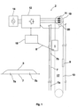
- the elevator system of Fig. 1 comprises an elevator car 1 and also an electric drive 2 for moving the elevator car in the elevator hoistway 17 according to a movement profile 3 of the elevator car, which profile is formed by the elevator control unit 18.
- the electric drive 2 comprises a hoisting machine 19 disposed in the top part of the elevator hoistway 17, which hoisting machine comprises an alternating current motor 11 as the power producing part.
- the electric drive 2 comprises a frequency converter 12 for supplying variable-amplitude and variable-frequency current to the alternating current motor 11.
- the elevator car 1 is suspended in the elevator hoistway 17 with suspension means, such as ropes, a belt or corresponding, passing via the traction sheave of the hoisting machine 19 (in the following the term “elevator rope” will be used generally to refer to said suspension means).
- the hoisting machine 19 is, in this embodiment of the invention, fixed to the guide rail (not in figure) of the elevator car, in a space between the guide rail and the wall of the elevator hoistway 17.
- the hoisting machine 19 could, however, also be fixed to a machine bedplate, and the hoisting machine could also be disposed elsewhere in the elevator hoistway or in a machine room instead of in the elevator hoistway.
- the elevator assembly is implemented without a compensating rope; the elevator assembly could, however, also comprise one or more compensating ropes, which in this case could be fitted into the elevator assembly e.g. in the manner marked in Fig. 1 with a dashed line 13.
- the elevator control unit 18 sends the movement profile 3 of the elevator car it has formed to the frequency converter 12 via a data transfer bus between the elevator control unit 18 and the frequency converter 12.
- the frequency converter 12 measures the speed of rotation of the rotor of the elevator motor 11 with a speed measurement sensor 20 and sets the torque of the elevator car by adjusting the current running in the elevator motor such that the movement of the rotor of the elevator car, and thereby the movement of the elevator car, approaches the aforementioned movement profile 3 of the elevator car.
- the elevator control unit 18 determines the position 7 of the elevator car 1 in the elevator hoistway 17.
- the determination of the position can be implemented e.g. by integrating the speed of rotation of the rotor of the elevator motor 11; the position can also be determined e.g. by integrating the speed data/acceleration data of the elevator car expressed by an acceleration sensor or speed sensor fitted in connection with the elevator car 1.
- the determination of the position 7 of the elevator car 1 can also be further adjusted at the point of the door zones 21.
- the elevator control unit 18 determines the movement profile 3 of the elevator car by changing the value for the acceleration/deceleration 5a, 5b of the elevator car in the movement profile of the elevator car in the manner presented in Figs. 3a, 3b when the position 7 of the elevator car 1 changes.
- FIG. 3a presents a situation in which the elevator car 1 is loaded to be essentially heavier than a balanced load. Information about the load 8 of the elevator car is obtained from the load-weighing sensor in the elevator car, but the load 8 of the elevator car could also be estimated e.g. on the basis of the currents of the elevator motor.
- Fig. 3a presents the value for the acceleration/deceleration of the elevator car to be used in the movement profile 3 of the elevator car when the position 7 of the elevator car in the elevator hoistway 17 changes from down upwards.
- the elevator control unit 18 limits the loading of the electric drive 2 to the limit value for the maximum permitted loading by selecting the acceleration and/or deceleration 5a of the elevator car to be used in the movement profile 3 of the elevator car when lower down in the elevator hoistway, e.g. at the point 7a, to be smaller than the acceleration and/or deceleration 5b of the elevator car to be used when higher up in the elevator hoistway, e.g. at the point 7b.
- the elevator car 1 is loaded to be essentially lighter than a balanced load.
- the elevator control unit 18 limits the loading of the electric drive 2 to the limit value for the maximum permitted loading by selecting the acceleration and/or deceleration 5a of the elevator car to be used in the movement profile 3 of the elevator car when lower down in the elevator hoistway, e.g. at the point 7a, to be greater than the acceleration and/or deceleration 5b of the elevator car to be used when higher up in the elevator hoistway, e.g. at the point 7b.
- the elevator can be driven with the electric drive closer than in prior art to the upper limit for performance that is set by the maximum permitted loading of the electric drive.
- the weight of the elevator ropes suspended in the top part of the elevator hoistway and disposed between the traction sheave of the hoisting machine 19 and the elevator car 1 decreases when the elevator car 1 moves upwards and increases when the elevator car 1 moves downwards.
- the weight of the elevator ropes disposed between the traction sheave of the hoisting machine 19 and the counterweight 9 increases when the elevator car 1 moves upwards and decreases when the elevator car 1 moves downwards.
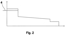
- Fig. 2 presents the current of an elevator motor moving an elevator car at constant speed and constant acceleration according to prior art, described in relation to time.
- a permanent-magnet synchronous motor is used here as the elevator motor.
- an essentially fully-loaded elevator car drives in the elevator hoistway from down upwards, accelerating first to maximum speed, after which the elevator car drives for a certain time at maximum speed, after which the elevator car decelerates, stopping at the destination floor.
- the elevator motor and thereby also the current of the frequency converter supplying the elevator motor is at its maximum during the initial acceleration; during constant speed the current gradually decreases owing to the changes of the weight of the aforementioned elevator ropes disposed between the elevator car and traction sheave as well as between the counterweight and the traction sheave.
- the magnitude of the current varies in essentially the same way in a situation in which an essentially empty elevator car drives from up to down in the elevator hoistway, accelerating first to maximum speed, after which the elevator car drives for a certain time at maximum speed, after which the elevator car decelerates, stopping at the destination floor.
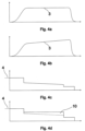
- Figs. 4a and 4b present first the graphs 3 according to the invention of the movement profile of an elevator car in relation to time, and Figs. 4c, 4d present the corresponding currents of the elevator car.
- Fig. 4a presents the speed profile 3 of the elevator car according to the first embodiment of the invention, in which speed profile the acceleration/deceleration of the elevator car is changed during a run with the elevator. In this case the elevator car starts moving from the bottom part of the hoistway with limited acceleration and stops in the top part of the hoistway with a deceleration that is greater than this.
- Fig. 4a and 4b present first the graphs 3 according to the invention of the movement profile of an elevator car in relation to time
- Figs. 4c, 4d present the corresponding currents of the elevator car.
- Fig. 4a presents the speed profile 3 of the elevator car according to the first embodiment of the invention, in which speed profile the acceleration/deceleration of the elevator car is changed during a run with the elevator. In this case
- FIG. 4b not belonging to the invention - presents the speed profile of the elevator car, in which speed profile also the maximum speed of the elevator car, in addition to the acceleration/deceleration of the elevator car, is changed during a run with the elevator, for increasing the transport capacity of the elevator and for shortening the door-to-door time of the elevator.
- the graphs of Figs. 4a - 4d are presented in the loading state according to Fig. 2 , so that the motor currents can be compared to each other.
- Marked in Fig. 4d is a field weakening current 10, which is supplied to the permanent-magnet synchronous motor moving the elevator car for weakening the rotor excitation.
- the aforementioned limit value 4 for maximum permitted current of the elevator motor and/or of the frequency converter can be determined e.g. on the basis of the copper losses of the motor or on the basis of the current endurance of the IGBT transistors of the frequency converter. Also the cooling of the elevator motor and/or of the frequency converter can affect the limit value for maximum permitted current such that by enhancing the cooling the limit value for maximum permitted current can be increased.
Landscapes
- Engineering & Computer Science (AREA)
- Automation & Control Theory (AREA)
- Elevator Control (AREA)
Claims (10)
- Aufzugssystem, das umfasst:eine Aufzugskabine (1);einen Motorantrieb (2) zum Bewegen der Aufzugskabine gemäß einem Bewegungsprofil (3), das für die Bewegung der Aufzugskabine zu bestimmen ist;wobei die Belastung des vorgenannten Motorantriebs (2) eingerichtet ist, auf den Grenzwert (4) für die maximal zulässige Belastung des Motorantriebs (2) begrenzt zu sein durch ein Ändern des Wertes einer Bewegungsgröße (5a, 5b; 6a, 6b) der Aufzugskabine in dem Bewegungsprofil (3) der Aufzugskabine (1), wenn sich die Position (7) der Aufzugskabine ändert, dadurch gekennzeichnet,die benannte Bewegungsgröße der Aufzugskabine die positive oder negative Beschleunigung der Aufzugskabine ist, und dass die Belastung des Motorantriebs (2) eingerichtet ist, auf den Grenzwert (4) für die maximal zulässige Belastung begrenzt zu sein durch ein Reduzieren der Beschleunigung der Aufzugskabine und/oder der Verzögerung (5a) der Aufzugskabine im Bewegungsprofil (3) der Aufzugskabine (1) in Bezug auf die Beschleunigung/Verzögerung (5b) der Aufzugskabine (1) reduziert wird, wenn sich die Aufzugskabine (1) weiter oben in einem Aufzugsschacht (17) befindet.
- Aufzugssystem nach Anspruch 1, dadurch gekennzeichnet, dass die Belastung des Motorantriebs eingerichtet ist, auf den Grenzwert (4) für die maximal zulässige Belastung begrenzt wird durch ein Ändern der Wertes einer Bewegungsgröße (5a, 5b; 6a, 6b) der Aufzugskabine im Bewegungsprofil (3) der Aufzugskabine geändert wird, wenn sich die Last (8) der Aufzugskabine ändert.
- Aufzugssystem nach einem der vorhergehenden Ansprüche, dadurch gekennzeichnet, dass das Aufzugssystem ein Gegengewicht (9) umfasst.
- Aufzugssystem nach Anspruch 3, dadurch gekennzeichnet, dass die Aufzugskabine (1) leer ist oder die Aufzugskabine (1) beladen ist, um leichter als eine ausgeglichene Last oder schwerer als eine ausgeglichene Last zu sein.
- Aufzugssystem nach Anspruch 3 oder 4, dadurch gekennzeichnet, dass die Belastung des Motorantriebs eingerichtet ist, auf den Grenzwert (4) für die maximal zulässige Belastung begrenzt zu sein durch ein Reduzieren der Beschleunigung, vorzugsweise der maximalen Momentanbeschleunigung, der Aufzugskabine und/oder der Verzögerung, vorzugsweise der maximalen Momentanverzögerung, der Aufzugskabine (5a) in dem Bewegungsprofil (3) der Aufzugskabine, wenn sie beladen ist, um schwerer als die ausgeglichene Last zu sein, bezogen auf die Beschleunigung, vorzugsweise die maximale Momentanbeschleunigung, /Verzögerung, vorzugsweise die maximale Momentanverzögerung, (5b) der Aufzugskabine, wenn sie sich weiter oben befindet und in einer entsprechenden Weise beladen ist.
- Aufzugssystem nach einem der Ansprüche 3 bis 5, dadurch gekennzeichnet, dass die Belastung des Motorantriebs eingerichtet ist, auf den Grenzwert (4) für die maximal zulässige Belastung begrenzt zu sein durch ein Reduzieren der Beschleunigung, vorzugsweise der maximalen Momentanbeschleunigung, der Aufzugskabine und/oder der Verzögerung, vorzugsweise der maximalen Momentanverzögerung, der Aufzugskabine (5b) in dem Bewegungsprofil (3) der Aufzugskabine, wenn sie beladen ist, um leichter als die ausgeglichene Last zu sein oder wenn sie leer ist, bezogen auf die Beschleunigung, vorzugsweise die maximale Momentanbeschleunigung, /Verzögerung, vorzugsweise die maximale Momentanverzögerung, (5a) der Aufzugskabine, wenn sie sich weiter unten befindet und in einer entsprechenden Weise beladen ist.
- Aufzugssystem nach einem der Ansprüche 4 bis 6, dadurch gekennzeichnet, dass der Motorantrieb (2) eingerichtet ist, die Feldschwächung (10) des Aufzugsmotors zur Erhöhung der Maximalgeschwindigkeit (6a, 6b) der Aufzugskabine zu erhöhen.
- Aufzugssystem nach einem der vorhergehenden Ansprüche, dadurch gekennzeichnet, dass der vorgenannte Motorantrieb (2) ein elektrischer Antrieb eines Aufzugs ist.
- Aufzugssystem nach Anspruch 8, dadurch gekennzeichnet, dass der elektrische Antrieb eines Aufzugs einen Wechselstrommotor (11) und zudem einen Frequenzumrichter (12) zum Versorgen des Wechselstrommotors mit Strom umfasst.
- Aufzugssystem nach einem der vorhergehenden Ansprüche, dadurch gekennzeichnet, dass die Aufzugsanlage ohne ein Ausgleichsseil (13) ausgeführt ist.
Applications Claiming Priority (2)
| Application Number | Priority Date | Filing Date | Title |
|---|---|---|---|
| FI20105401A FI121879B (fi) | 2010-04-16 | 2010-04-16 | Hissijärjestelmä |
| PCT/FI2011/000021 WO2011128493A1 (en) | 2010-04-16 | 2011-04-13 | Elevator system |
Publications (4)
| Publication Number | Publication Date |
|---|---|
| EP2558394A1 EP2558394A1 (de) | 2013-02-20 |
| EP2558394A4 EP2558394A4 (de) | 2016-11-02 |
| EP2558394B1 EP2558394B1 (de) | 2022-06-01 |
| EP2558394B2 true EP2558394B2 (de) | 2025-01-08 |
Family
ID=42133245
Family Applications (1)
| Application Number | Title | Priority Date | Filing Date |
|---|---|---|---|
| EP11768498.5A Active EP2558394B2 (de) | 2010-04-16 | 2011-04-13 | Aufzugsystem |
Country Status (5)
| Country | Link |
|---|---|
| US (1) | US8789660B2 (de) |
| EP (1) | EP2558394B2 (de) |
| CN (1) | CN102939255B (de) |
| FI (1) | FI121879B (de) |
| WO (1) | WO2011128493A1 (de) |
Families Citing this family (8)
| Publication number | Priority date | Publication date | Assignee | Title |
|---|---|---|---|---|
| EP2454182B1 (de) * | 2009-07-15 | 2019-08-28 | Otis Elevator Company | Energieeinsparung mit optimierten bewegungsprofilen |
| FI20105033L (fi) * | 2010-01-18 | 2011-07-19 | Kone Corp | Menetelmä hissikorin liikkeen valvomiseksi sekä hissijärjestelmä |
| FI123182B (fi) * | 2012-02-16 | 2012-12-14 | Kone Corp | Menetelmä hissin ohjaamiseksi ja hissi |
| EP2835334B1 (de) * | 2013-08-08 | 2021-09-29 | KONE Corporation | Verfahren zur Steuerung eines Aufzugs und Aufzug |
| CN104444710A (zh) * | 2014-09-28 | 2015-03-25 | 苏州福沃斯电梯有限公司 | 一种升降电梯 |
| US9862568B2 (en) | 2016-02-26 | 2018-01-09 | Otis Elevator Company | Elevator run profile modification for smooth rescue |
| CN109179104A (zh) * | 2018-11-16 | 2019-01-11 | 迅达(中国)电梯有限公司 | 电梯控制方法 |
| US20230399196A1 (en) * | 2022-05-24 | 2023-12-14 | Otis Elevator Company | Robot-specific elevator systems |
Citations (1)
| Publication number | Priority date | Publication date | Assignee | Title |
|---|---|---|---|---|
| EP1731466A1 (de) † | 2004-03-29 | 2006-12-13 | Mitsubishi Denki Kabushiki Kaisha | Aufzugssteuervorrichtung |
Family Cites Families (21)
| Publication number | Priority date | Publication date | Assignee | Title |
|---|---|---|---|---|
| JPS5834389B2 (ja) * | 1977-11-24 | 1983-07-26 | 三菱電機株式会社 | 交流エレベ−タの速度制御装置 |
| JPS5842573A (ja) * | 1981-09-04 | 1983-03-12 | 株式会社日立製作所 | エレベ−タ−の制御装置 |
| US4751984A (en) * | 1985-05-03 | 1988-06-21 | Otis Elevator Company | Dynamically generated adaptive elevator velocity profile |
| US5035301A (en) * | 1989-07-03 | 1991-07-30 | Otis Elevator Company | Elevator speed dictation system |
| US5241141A (en) * | 1990-09-17 | 1993-08-31 | Otis Elevator Company | Elevator profile selection based on absence or presence of passengers |
| JP3153604B2 (ja) * | 1992-01-27 | 2001-04-09 | 株式会社東芝 | エレベーターの制御装置 |
| ES2137213T3 (es) * | 1993-09-15 | 1999-12-16 | Inventio Ag | Procedimiento y dispositivo para el control de un ascensor hidraulico. |
| KR100259511B1 (ko) * | 1998-03-26 | 2000-07-01 | 이종수 | 엘리베이터의 위치 제어 방법 |
| KR100312768B1 (ko) * | 1998-08-28 | 2002-05-09 | 장병우 | 엘리베이터의속도지령장치및방법 |
| JP2001026380A (ja) | 1999-07-14 | 2001-01-30 | Nippon Otis Elevator Co | エレベータの速度制御装置 |
| JP4283963B2 (ja) * | 2000-02-28 | 2009-06-24 | 三菱電機株式会社 | エレベータの制御装置 |
| AU2001281851A1 (en) * | 2000-07-17 | 2002-01-30 | Abm Greiffenberger Antriebstechnik Gmbh | Method for sensorless drive control of an electric vehicle and drive control operating according to said method |
| WO2005049468A1 (ja) * | 2003-11-21 | 2005-06-02 | Mitsubishi Denki Kabushiki Kaisha | エレベータ装置 |
| CN101044079B (zh) * | 2004-10-14 | 2010-09-29 | 奥蒂斯电梯公司 | 用于限制功率消耗的提升运动轨迹控制 |
| FI119878B (fi) * | 2005-02-04 | 2009-04-30 | Kone Corp | Järjestelmä ja menetelmä hissin turvallisuuden parantamiseksi |
| JP4584019B2 (ja) * | 2005-05-10 | 2010-11-17 | 三菱電機ビルテクノサービス株式会社 | エレベータの制御装置 |
| EP1930274B1 (de) * | 2005-09-30 | 2014-03-12 | Mitsubishi Denki Kabushiki Kaisha | Vorrichtung zur steuerung des betriebs eines aufzugs |
| FI120070B (fi) | 2007-10-01 | 2009-06-15 | Kone Corp | Sähkökäytön annon rajoittaminen sekä hissin suojaus |
| WO2009084076A1 (ja) * | 2007-12-27 | 2009-07-09 | Mitsubishi Electric Corporation | エレベータ装置 |
| GB2476590B (en) * | 2008-08-04 | 2013-01-09 | Otis Elevator Co | Elevator motion profile control |
| FI20105587A0 (fi) * | 2010-05-25 | 2010-05-25 | Kone Corp | Menetelmä hissikokoonpanon kuormituksen rajoittamiseksi sekä hissikokoonpano |
-
2010
- 2010-04-16 FI FI20105401A patent/FI121879B/fi active IP Right Grant
-
2011
- 2011-04-13 EP EP11768498.5A patent/EP2558394B2/de active Active
- 2011-04-13 CN CN201180029676.8A patent/CN102939255B/zh active Active
- 2011-04-13 WO PCT/FI2011/000021 patent/WO2011128493A1/en not_active Ceased
-
2012
- 2012-10-15 US US13/652,157 patent/US8789660B2/en active Active
Patent Citations (1)
| Publication number | Priority date | Publication date | Assignee | Title |
|---|---|---|---|---|
| EP1731466A1 (de) † | 2004-03-29 | 2006-12-13 | Mitsubishi Denki Kabushiki Kaisha | Aufzugssteuervorrichtung |
Also Published As
| Publication number | Publication date |
|---|---|
| CN102939255B (zh) | 2015-08-19 |
| FI121879B (fi) | 2011-05-31 |
| CN102939255A (zh) | 2013-02-20 |
| US8789660B2 (en) | 2014-07-29 |
| EP2558394B1 (de) | 2022-06-01 |
| WO2011128493A1 (en) | 2011-10-20 |
| EP2558394A4 (de) | 2016-11-02 |
| FI20105401A0 (fi) | 2010-04-16 |
| US20130075200A1 (en) | 2013-03-28 |
| EP2558394A1 (de) | 2013-02-20 |
Similar Documents
| Publication | Publication Date | Title |
|---|---|---|
| EP2558394B2 (de) | Aufzugsystem | |
| CN101816122B (zh) | 对电驱动器的输出的限制和对电梯的保护 | |
| US8985280B2 (en) | Method and elevator assemblies limiting loading of elevators by modifying movement magnitude value | |
| JP4964903B2 (ja) | エレベータ装置 | |
| EP2454182B1 (de) | Energieeinsparung mit optimierten bewegungsprofilen | |
| WO2007132523A1 (ja) | エレベータの制御装置 | |
| CN101044079B (zh) | 用于限制功率消耗的提升运动轨迹控制 | |
| EP1731466B1 (de) | Aufzugssteuervorrichtung | |
| CN1792757A (zh) | 电梯系统 | |
| CN1802305A (zh) | 电梯的控制 | |
| CN101223096B (zh) | 电梯的速度控制装置和速度控制方法 | |
| EP1721855A2 (de) | Aufzugssteuereinheit | |
| JP2004137003A (ja) | エレベーター装置 | |
| JP5264145B2 (ja) | エレベータ制御装置 | |
| JP2007008714A (ja) | エレベータの制御装置及びエレベータの改修方法 | |
| HK1171002A (en) | Energy savings with optimized motion profiles | |
| JP2012111580A (ja) | エレベーターの制御装置 | |
| HK1107071A1 (en) | Control device for rotating machine for elevator |
Legal Events
| Date | Code | Title | Description |
|---|---|---|---|
| PUAI | Public reference made under article 153(3) epc to a published international application that has entered the european phase |
Free format text: ORIGINAL CODE: 0009012 |
|
| 17P | Request for examination filed |
Effective date: 20121011 |
|
| AK | Designated contracting states |
Kind code of ref document: A1 Designated state(s): AL AT BE BG CH CY CZ DE DK EE ES FI FR GB GR HR HU IE IS IT LI LT LU LV MC MK MT NL NO PL PT RO RS SE SI SK SM TR |
|
| DAX | Request for extension of the european patent (deleted) | ||
| RA4 | Supplementary search report drawn up and despatched (corrected) |
Effective date: 20160930 |
|
| RIC1 | Information provided on ipc code assigned before grant |
Ipc: B66B 1/30 20060101AFI20160926BHEP |
|
| STAA | Information on the status of an ep patent application or granted ep patent |
Free format text: STATUS: EXAMINATION IS IN PROGRESS |
|
| 17Q | First examination report despatched |
Effective date: 20200617 |
|
| GRAP | Despatch of communication of intention to grant a patent |
Free format text: ORIGINAL CODE: EPIDOSNIGR1 |
|
| STAA | Information on the status of an ep patent application or granted ep patent |
Free format text: STATUS: GRANT OF PATENT IS INTENDED |
|
| INTG | Intention to grant announced |
Effective date: 20211215 |
|
| GRAS | Grant fee paid |
Free format text: ORIGINAL CODE: EPIDOSNIGR3 |
|
| GRAA | (expected) grant |
Free format text: ORIGINAL CODE: 0009210 |
|
| STAA | Information on the status of an ep patent application or granted ep patent |
Free format text: STATUS: THE PATENT HAS BEEN GRANTED |
|
| AK | Designated contracting states |
Kind code of ref document: B1 Designated state(s): AL AT BE BG CH CY CZ DE DK EE ES FI FR GB GR HR HU IE IS IT LI LT LU LV MC MK MT NL NO PL PT RO RS SE SI SK SM TR |
|
| REG | Reference to a national code |
Ref country code: GB Ref legal event code: FG4D |
|
| REG | Reference to a national code |
Ref country code: AT Ref legal event code: REF Ref document number: 1495270 Country of ref document: AT Kind code of ref document: T Effective date: 20220615 Ref country code: CH Ref legal event code: EP Ref country code: DE Ref legal event code: R096 Ref document number: 602011072955 Country of ref document: DE |
|
| REG | Reference to a national code |
Ref country code: IE Ref legal event code: FG4D |
|
| REG | Reference to a national code |
Ref country code: LT Ref legal event code: MG9D |
|
| REG | Reference to a national code |
Ref country code: NL Ref legal event code: MP Effective date: 20220601 |
|
| PG25 | Lapsed in a contracting state [announced via postgrant information from national office to epo] |
Ref country code: SE Free format text: LAPSE BECAUSE OF FAILURE TO SUBMIT A TRANSLATION OF THE DESCRIPTION OR TO PAY THE FEE WITHIN THE PRESCRIBED TIME-LIMIT Effective date: 20220601 Ref country code: NO Free format text: LAPSE BECAUSE OF FAILURE TO SUBMIT A TRANSLATION OF THE DESCRIPTION OR TO PAY THE FEE WITHIN THE PRESCRIBED TIME-LIMIT Effective date: 20220901 Ref country code: LT Free format text: LAPSE BECAUSE OF FAILURE TO SUBMIT A TRANSLATION OF THE DESCRIPTION OR TO PAY THE FEE WITHIN THE PRESCRIBED TIME-LIMIT Effective date: 20220601 Ref country code: HR Free format text: LAPSE BECAUSE OF FAILURE TO SUBMIT A TRANSLATION OF THE DESCRIPTION OR TO PAY THE FEE WITHIN THE PRESCRIBED TIME-LIMIT Effective date: 20220601 Ref country code: GR Free format text: LAPSE BECAUSE OF FAILURE TO SUBMIT A TRANSLATION OF THE DESCRIPTION OR TO PAY THE FEE WITHIN THE PRESCRIBED TIME-LIMIT Effective date: 20220902 Ref country code: FI Free format text: LAPSE BECAUSE OF FAILURE TO SUBMIT A TRANSLATION OF THE DESCRIPTION OR TO PAY THE FEE WITHIN THE PRESCRIBED TIME-LIMIT Effective date: 20220601 Ref country code: ES Free format text: LAPSE BECAUSE OF FAILURE TO SUBMIT A TRANSLATION OF THE DESCRIPTION OR TO PAY THE FEE WITHIN THE PRESCRIBED TIME-LIMIT Effective date: 20220601 Ref country code: BG Free format text: LAPSE BECAUSE OF FAILURE TO SUBMIT A TRANSLATION OF THE DESCRIPTION OR TO PAY THE FEE WITHIN THE PRESCRIBED TIME-LIMIT Effective date: 20220901 |
|
| REG | Reference to a national code |
Ref country code: AT Ref legal event code: MK05 Ref document number: 1495270 Country of ref document: AT Kind code of ref document: T Effective date: 20220601 |
|
| PG25 | Lapsed in a contracting state [announced via postgrant information from national office to epo] |
Ref country code: RS Free format text: LAPSE BECAUSE OF FAILURE TO SUBMIT A TRANSLATION OF THE DESCRIPTION OR TO PAY THE FEE WITHIN THE PRESCRIBED TIME-LIMIT Effective date: 20220601 Ref country code: PL Free format text: LAPSE BECAUSE OF FAILURE TO SUBMIT A TRANSLATION OF THE DESCRIPTION OR TO PAY THE FEE WITHIN THE PRESCRIBED TIME-LIMIT Effective date: 20220601 Ref country code: LV Free format text: LAPSE BECAUSE OF FAILURE TO SUBMIT A TRANSLATION OF THE DESCRIPTION OR TO PAY THE FEE WITHIN THE PRESCRIBED TIME-LIMIT Effective date: 20220601 |
|
| PG25 | Lapsed in a contracting state [announced via postgrant information from national office to epo] |
Ref country code: NL Free format text: LAPSE BECAUSE OF FAILURE TO SUBMIT A TRANSLATION OF THE DESCRIPTION OR TO PAY THE FEE WITHIN THE PRESCRIBED TIME-LIMIT Effective date: 20220601 |
|
| PG25 | Lapsed in a contracting state [announced via postgrant information from national office to epo] |
Ref country code: SM Free format text: LAPSE BECAUSE OF FAILURE TO SUBMIT A TRANSLATION OF THE DESCRIPTION OR TO PAY THE FEE WITHIN THE PRESCRIBED TIME-LIMIT Effective date: 20220601 Ref country code: SK Free format text: LAPSE BECAUSE OF FAILURE TO SUBMIT A TRANSLATION OF THE DESCRIPTION OR TO PAY THE FEE WITHIN THE PRESCRIBED TIME-LIMIT Effective date: 20220601 Ref country code: RO Free format text: LAPSE BECAUSE OF FAILURE TO SUBMIT A TRANSLATION OF THE DESCRIPTION OR TO PAY THE FEE WITHIN THE PRESCRIBED TIME-LIMIT Effective date: 20220601 Ref country code: PT Free format text: LAPSE BECAUSE OF FAILURE TO SUBMIT A TRANSLATION OF THE DESCRIPTION OR TO PAY THE FEE WITHIN THE PRESCRIBED TIME-LIMIT Effective date: 20221003 Ref country code: EE Free format text: LAPSE BECAUSE OF FAILURE TO SUBMIT A TRANSLATION OF THE DESCRIPTION OR TO PAY THE FEE WITHIN THE PRESCRIBED TIME-LIMIT Effective date: 20220601 Ref country code: CZ Free format text: LAPSE BECAUSE OF FAILURE TO SUBMIT A TRANSLATION OF THE DESCRIPTION OR TO PAY THE FEE WITHIN THE PRESCRIBED TIME-LIMIT Effective date: 20220601 Ref country code: AT Free format text: LAPSE BECAUSE OF FAILURE TO SUBMIT A TRANSLATION OF THE DESCRIPTION OR TO PAY THE FEE WITHIN THE PRESCRIBED TIME-LIMIT Effective date: 20220601 |
|
| PG25 | Lapsed in a contracting state [announced via postgrant information from national office to epo] |
Ref country code: IS Free format text: LAPSE BECAUSE OF FAILURE TO SUBMIT A TRANSLATION OF THE DESCRIPTION OR TO PAY THE FEE WITHIN THE PRESCRIBED TIME-LIMIT Effective date: 20221001 |
|
| REG | Reference to a national code |
Ref country code: DE Ref legal event code: R026 Ref document number: 602011072955 Country of ref document: DE |
|
| PLBI | Opposition filed |
Free format text: ORIGINAL CODE: 0009260 |
|
| PLAX | Notice of opposition and request to file observation + time limit sent |
Free format text: ORIGINAL CODE: EPIDOSNOBS2 |
|
| PG25 | Lapsed in a contracting state [announced via postgrant information from national office to epo] |
Ref country code: AL Free format text: LAPSE BECAUSE OF FAILURE TO SUBMIT A TRANSLATION OF THE DESCRIPTION OR TO PAY THE FEE WITHIN THE PRESCRIBED TIME-LIMIT Effective date: 20220601 |
|
| 26 | Opposition filed |
Opponent name: OTIS ELEVATOR COMPANY Effective date: 20230301 |
|
| PG25 | Lapsed in a contracting state [announced via postgrant information from national office to epo] |
Ref country code: DK Free format text: LAPSE BECAUSE OF FAILURE TO SUBMIT A TRANSLATION OF THE DESCRIPTION OR TO PAY THE FEE WITHIN THE PRESCRIBED TIME-LIMIT Effective date: 20220601 |
|
| PG25 | Lapsed in a contracting state [announced via postgrant information from national office to epo] |
Ref country code: SI Free format text: LAPSE BECAUSE OF FAILURE TO SUBMIT A TRANSLATION OF THE DESCRIPTION OR TO PAY THE FEE WITHIN THE PRESCRIBED TIME-LIMIT Effective date: 20220601 |
|
| PLBB | Reply of patent proprietor to notice(s) of opposition received |
Free format text: ORIGINAL CODE: EPIDOSNOBS3 |
|
| P01 | Opt-out of the competence of the unified patent court (upc) registered |
Effective date: 20230525 |
|
| REG | Reference to a national code |
Ref country code: CH Ref legal event code: PL |
|
| GBPC | Gb: european patent ceased through non-payment of renewal fee |
Effective date: 20230413 |
|
| PG25 | Lapsed in a contracting state [announced via postgrant information from national office to epo] |
Ref country code: LU Free format text: LAPSE BECAUSE OF NON-PAYMENT OF DUE FEES Effective date: 20230413 |
|
| REG | Reference to a national code |
Ref country code: BE Ref legal event code: MM Effective date: 20230430 |
|
| PG25 | Lapsed in a contracting state [announced via postgrant information from national office to epo] |
Ref country code: MC Free format text: LAPSE BECAUSE OF FAILURE TO SUBMIT A TRANSLATION OF THE DESCRIPTION OR TO PAY THE FEE WITHIN THE PRESCRIBED TIME-LIMIT Effective date: 20220601 |
|
| PG25 | Lapsed in a contracting state [announced via postgrant information from national office to epo] |
Ref country code: GB Free format text: LAPSE BECAUSE OF NON-PAYMENT OF DUE FEES Effective date: 20230413 |
|
| PG25 | Lapsed in a contracting state [announced via postgrant information from national office to epo] |
Ref country code: MC Free format text: LAPSE BECAUSE OF FAILURE TO SUBMIT A TRANSLATION OF THE DESCRIPTION OR TO PAY THE FEE WITHIN THE PRESCRIBED TIME-LIMIT Effective date: 20220601 Ref country code: LI Free format text: LAPSE BECAUSE OF NON-PAYMENT OF DUE FEES Effective date: 20230430 Ref country code: IT Free format text: LAPSE BECAUSE OF FAILURE TO SUBMIT A TRANSLATION OF THE DESCRIPTION OR TO PAY THE FEE WITHIN THE PRESCRIBED TIME-LIMIT Effective date: 20220601 Ref country code: GB Free format text: LAPSE BECAUSE OF NON-PAYMENT OF DUE FEES Effective date: 20230413 Ref country code: FR Free format text: LAPSE BECAUSE OF NON-PAYMENT OF DUE FEES Effective date: 20230430 Ref country code: CH Free format text: LAPSE BECAUSE OF NON-PAYMENT OF DUE FEES Effective date: 20230430 |
|
| REG | Reference to a national code |
Ref country code: IE Ref legal event code: MM4A |
|
| PG25 | Lapsed in a contracting state [announced via postgrant information from national office to epo] |
Ref country code: BE Free format text: LAPSE BECAUSE OF NON-PAYMENT OF DUE FEES Effective date: 20230430 |
|
| PG25 | Lapsed in a contracting state [announced via postgrant information from national office to epo] |
Ref country code: IE Free format text: LAPSE BECAUSE OF NON-PAYMENT OF DUE FEES Effective date: 20230413 |
|
| PG25 | Lapsed in a contracting state [announced via postgrant information from national office to epo] |
Ref country code: IE Free format text: LAPSE BECAUSE OF NON-PAYMENT OF DUE FEES Effective date: 20230413 |
|
| PG25 | Lapsed in a contracting state [announced via postgrant information from national office to epo] |
Ref country code: BG Free format text: LAPSE BECAUSE OF FAILURE TO SUBMIT A TRANSLATION OF THE DESCRIPTION OR TO PAY THE FEE WITHIN THE PRESCRIBED TIME-LIMIT Effective date: 20220601 |
|
| PG25 | Lapsed in a contracting state [announced via postgrant information from national office to epo] |
Ref country code: BG Free format text: LAPSE BECAUSE OF FAILURE TO SUBMIT A TRANSLATION OF THE DESCRIPTION OR TO PAY THE FEE WITHIN THE PRESCRIBED TIME-LIMIT Effective date: 20220601 |
|
| PUAH | Patent maintained in amended form |
Free format text: ORIGINAL CODE: 0009272 |
|
| STAA | Information on the status of an ep patent application or granted ep patent |
Free format text: STATUS: PATENT MAINTAINED AS AMENDED |
|
| 27A | Patent maintained in amended form |
Effective date: 20250108 |
|
| AK | Designated contracting states |
Kind code of ref document: B2 Designated state(s): AL AT BE BG CH CY CZ DE DK EE ES FI FR GB GR HR HU IE IS IT LI LT LU LV MC MK MT NL NO PL PT RO RS SE SI SK SM TR |
|
| REG | Reference to a national code |
Ref country code: DE Ref legal event code: R102 Ref document number: 602011072955 Country of ref document: DE |
|
| PGFP | Annual fee paid to national office [announced via postgrant information from national office to epo] |
Ref country code: DE Payment date: 20250422 Year of fee payment: 15 |
|
| PG25 | Lapsed in a contracting state [announced via postgrant information from national office to epo] |
Ref country code: CY Free format text: LAPSE BECAUSE OF FAILURE TO SUBMIT A TRANSLATION OF THE DESCRIPTION OR TO PAY THE FEE WITHIN THE PRESCRIBED TIME-LIMIT; INVALID AB INITIO Effective date: 20110413 |
|
| PG25 | Lapsed in a contracting state [announced via postgrant information from national office to epo] |
Ref country code: HU Free format text: LAPSE BECAUSE OF FAILURE TO SUBMIT A TRANSLATION OF THE DESCRIPTION OR TO PAY THE FEE WITHIN THE PRESCRIBED TIME-LIMIT; INVALID AB INITIO Effective date: 20110413 |
|
| PG25 | Lapsed in a contracting state [announced via postgrant information from national office to epo] |
Ref country code: TR Free format text: LAPSE BECAUSE OF FAILURE TO SUBMIT A TRANSLATION OF THE DESCRIPTION OR TO PAY THE FEE WITHIN THE PRESCRIBED TIME-LIMIT Effective date: 20220601 |