EP2554397B1 - Prägestruktur - Google Patents
Prägestruktur Download PDFInfo
- Publication number
- EP2554397B1 EP2554397B1 EP11006475.5A EP11006475A EP2554397B1 EP 2554397 B1 EP2554397 B1 EP 2554397B1 EP 11006475 A EP11006475 A EP 11006475A EP 2554397 B1 EP2554397 B1 EP 2554397B1
- Authority
- EP
- European Patent Office
- Prior art keywords
- embossed structure
- displaying
- side walls
- grooves
- image
- Prior art date
- Legal status (The legal status is an assumption and is not a legal conclusion. Google has not performed a legal analysis and makes no representation as to the accuracy of the status listed.)
- Not-in-force
Links
- 238000004049 embossing Methods 0.000 claims description 14
- 239000000203 mixture Substances 0.000 claims description 2
- 230000001419 dependent effect Effects 0.000 description 6
- 239000011295 pitch Substances 0.000 description 6
- 239000007787 solid Substances 0.000 description 3
- 238000000034 method Methods 0.000 description 2
- 239000003086 colorant Substances 0.000 description 1
- 230000003247 decreasing effect Effects 0.000 description 1
- 238000005530 etching Methods 0.000 description 1
- 239000002184 metal Substances 0.000 description 1
- 238000003801 milling Methods 0.000 description 1
Images

Classifications
-
- B—PERFORMING OPERATIONS; TRANSPORTING
- B44—DECORATIVE ARTS
- B44B—MACHINES, APPARATUS OR TOOLS FOR ARTISTIC WORK, e.g. FOR SCULPTURING, GUILLOCHING, CARVING, BRANDING, INLAYING
- B44B5/00—Machines or apparatus for embossing decorations or marks, e.g. embossing coins
- B44B5/02—Dies; Accessories
- B44B5/026—Dies
-
- B—PERFORMING OPERATIONS; TRANSPORTING
- B32—LAYERED PRODUCTS
- B32B—LAYERED PRODUCTS, i.e. PRODUCTS BUILT-UP OF STRATA OF FLAT OR NON-FLAT, e.g. CELLULAR OR HONEYCOMB, FORM
- B32B38/00—Ancillary operations in connection with laminating processes
- B32B38/06—Embossing
-
- B—PERFORMING OPERATIONS; TRANSPORTING
- B41—PRINTING; LINING MACHINES; TYPEWRITERS; STAMPS
- B41J—TYPEWRITERS; SELECTIVE PRINTING MECHANISMS, i.e. MECHANISMS PRINTING OTHERWISE THAN FROM A FORME; CORRECTION OF TYPOGRAPHICAL ERRORS
- B41J3/00—Typewriters or selective printing or marking mechanisms characterised by the purpose for which they are constructed
- B41J3/38—Typewriters or selective printing or marking mechanisms characterised by the purpose for which they are constructed for embossing, e.g. for making matrices for stereotypes
-
- B—PERFORMING OPERATIONS; TRANSPORTING
- B42—BOOKBINDING; ALBUMS; FILES; SPECIAL PRINTED MATTER
- B42D—BOOKS; BOOK COVERS; LOOSE LEAVES; PRINTED MATTER CHARACTERISED BY IDENTIFICATION OR SECURITY FEATURES; PRINTED MATTER OF SPECIAL FORMAT OR STYLE NOT OTHERWISE PROVIDED FOR; DEVICES FOR USE THEREWITH AND NOT OTHERWISE PROVIDED FOR; MOVABLE-STRIP WRITING OR READING APPARATUS
- B42D25/00—Information-bearing cards or sheet-like structures characterised by identification or security features; Manufacture thereof
- B42D25/20—Information-bearing cards or sheet-like structures characterised by identification or security features; Manufacture thereof characterised by a particular use or purpose
- B42D25/29—Securities; Bank notes
-
- B—PERFORMING OPERATIONS; TRANSPORTING
- B42—BOOKBINDING; ALBUMS; FILES; SPECIAL PRINTED MATTER
- B42D—BOOKS; BOOK COVERS; LOOSE LEAVES; PRINTED MATTER CHARACTERISED BY IDENTIFICATION OR SECURITY FEATURES; PRINTED MATTER OF SPECIAL FORMAT OR STYLE NOT OTHERWISE PROVIDED FOR; DEVICES FOR USE THEREWITH AND NOT OTHERWISE PROVIDED FOR; MOVABLE-STRIP WRITING OR READING APPARATUS
- B42D25/00—Information-bearing cards or sheet-like structures characterised by identification or security features; Manufacture thereof
- B42D25/40—Manufacture
- B42D25/405—Marking
- B42D25/425—Marking by deformation, e.g. embossing
-
- B42D2035/20—
-
- B—PERFORMING OPERATIONS; TRANSPORTING
- B42—BOOKBINDING; ALBUMS; FILES; SPECIAL PRINTED MATTER
- B42D—BOOKS; BOOK COVERS; LOOSE LEAVES; PRINTED MATTER CHARACTERISED BY IDENTIFICATION OR SECURITY FEATURES; PRINTED MATTER OF SPECIAL FORMAT OR STYLE NOT OTHERWISE PROVIDED FOR; DEVICES FOR USE THEREWITH AND NOT OTHERWISE PROVIDED FOR; MOVABLE-STRIP WRITING OR READING APPARATUS
- B42D25/00—Information-bearing cards or sheet-like structures characterised by identification or security features; Manufacture thereof
- B42D25/30—Identification or security features, e.g. for preventing forgery
- B42D25/324—Reliefs
Definitions
- the present invention relates in a first aspect to an embossed structure for displaying different images in different viewing directions, according to the preamble of claim 1.
- the invention in a second aspect, relates to an embossed structure for displaying different images in different viewing directions, according the preamble of claim 10.
- a generic embossed structure on which the inventive embossed structure of claim 1 is based comprises a plurality of grooves, wherein each groove comprises a first side wall for displaying one line of a first image in a first viewing direction, and a second side wall for displaying one line of a second image in a second viewing direction.
- An equal embossing structure is the basis for the inventive embossed structure of claim 10, wherein the plurality of grooves is referred to as a first plurality of grooves. That is, an embossed structure being generic to the embossed structure of claim 10 comprises a first plurality of grooves in a first direction, wherein each groove of the first plurality comprises a first side wall for displaying one line of a first image in a first viewing direction, and a second side wall for displaying one line of a second image in a second viewing direction.
- Such embossed structures are known from EP 0 650 853 A1 .
- the solid objects are well-suited as a security means, wherein any solid object that is to be protected against counterfeiting can be provided with the embossed structure.
- the solid objects may be, for instance, coins, medals or plastic cards such as smart cards.
- Another field of application of the embossed structures may be displaying information or for entertainment.
- the known embossed structures are limited to displaying two different images in different viewing directions.
- DE 10 2009 004 128 A1 discloses an embossed structure according to the preamble of claim 1 for safety applications.
- the embossed comprises grooves on which sidewalls additional layers are applied. With these layers, two different images can be displayed in two different viewing angles. In one embodiment, one picture that comprises three different colours is displayed.
- WO 2004/030928 A1 an embossed structure according to the preamble of claim 10 constituting a security device is described.
- a surface of the device is furnished with a macro-embossing on which sidewalls micro-embossings are formed. In this way two different images can be displayed depending on the viewing angle.
- two sets of grooves are provided which extend in different directions for jointly displaying one image.
- Subject-matter of WO 2009/126030 A1 is an authentication feature which comprises a plurality of ridges on which a number of protrusions are formed. Thus two different images can be displayed depending on the viewing angle.
- a core idea of the inventive embossed structure of claim 1 resides in the provision of pits or deepening, which can also be referred to as recesses, in each region of the grooves, that is in the bottom section and the first and second side walls.
- the individual shape and/or size of each recess correspond to the pixel value of the pixel that is to be displayed with the respective recess.
- the images to be displayed may be grey-scale images, i.e., images with pixels whose pixel values constitute brightness levels.
- the amount of light that is scattered from each first side wall with its recesses in the first viewing direction is then proportional to the brightness levels of the respective pixels of the first image.
- the scattering of the light at the recesses into the viewing directions may be understood as any process that redirects light. That is, the light may be reflected and/or diffusely scattered.
- the light that is scattered is ambient light.
- the brightness levels of the scattered light for the respective recesses thus depend on the level of the ambient light.
- the embossed structure may also be regarded as a relief.
- the grooves may be referred to as furrows or as a fluting.
- Each groove displays one line of each respective image.
- the different pixels of one image line are displayed by the individual recesses along that groove.
- the image columns are then formed by arranged several grooves next to each other.
- the grooves are preferably straight and parallel to each other.
- the side walls may be understood as straight surfaces which are inclined relative to a normal of the embossed structure, i.e. the direction between the bottom section's deepest point and a top surface of the object.
- the recesses formed in these straight surfaces may extend across the whole height of the straight surface, resulting in no part of that straight surface being left.
- the recesses may leave an upper and/or a lower part of the straight surfaces; that is, the recesses may only be formed in a middle region of the straight surfaces.
- a white pixel, or a pixel with maximum brightness of one of the images, is displayed by scattering a maximum amount of light in the respective viewing direction. This maximum amount may be achieved by providing no recess at the respective bottom section or side wall. Recesses are then still provided for all other pixels that are not white.
- each line of each image consists of a plurality of pixels, for displaying the pixels of the respective line, and along each of the bottom section and the first and second side walls a number of recesses corresponding to the number of pixels of one line is provided.
- a period, i.e. distance, between recesses for displaying one image line is preferably chosen equal to the distance between two grooves.
- Image lines and image columns are then displayed with the same pitch.
- the recesses for displaying one image line may be arranged immediately next to each other, that is the length of a recess corresponds to the distance between two recesses.
- spaces may be left between neighbouring recesses.
- the respective bottom section or side wall remains unaltered, i.e. no recess is formed in that region.
- the summed length of such a pair of one recess and one pertaining space may then be common to all pairs of recesses and spaces.
- the length of a recess is chosen dependent on the brightness level to be displayed.
- a bright pixel may then correspond to a short recess with a large space to the next recess.
- a dark pixel may correspond to a long recess with a short space to the next recess.
- the profiles of all recesses belonging to one image may be formed identically. That is, the recesses that display one image may vary only in their lengths but not in their cross-sectional shape.
- the cross-sectional shape of the recesses may vary dependent on the brightness of the pixel to be displayed with the respective recess.
- the images to be displayed may be black and white images. Then, a recess corresponds to a black pixel of the image, and no recess at a certain region along one of the bottom sections or side walls corresponds to a white pixel.
- the bottom section may be provided with two kinds of recesses and the side walls may be provided with two other kinds of recesses.
- the profile of a region of the side walls without a recess may form a straight line. With no recess at the bottom section, the profile of one groove may thus have the shape of a "V".
- a preferred embodiment of the invention is characterized in that the recesses of the bottom section and of the side walls are each formed as steps.
- a step may comprise two straight surfaces. It is preferred that each step of one of the side walls has a ground surface and an inclined surface, and each step of the bottom section has a ground surface and two inclined surfaces.
- the ground surface of each step may be parallel to an object's top surface in which the embossed structure is formed.
- An inclined surface may be understood as being at an angle relative the ground surface, which angle is unequal to 90°.
- steps advantageously more clearly define the amount of light that is scattered in the respective directions.
- a preferable embodiment of the inventive embossed structures is characterized in that the pitch between two grooves is between 0.24mm and 0.36mm, preferably between 0.27mm and 0.33mm, and more preferably equal to 0.3mm.
- the pitch is to be understood as the distance from a center of one groove to a center of a neighbouring groove. It is generally possible that neighbouring grooves are directly juxtaposed to form an inverted "V" between them. Preferably, however, an even plateau may be formed between two grooves.
- the ground surfaces of the bottom section have widths between 0.01 mm and 0.1mm, preferably between 0.03mm and 0.07mm and more preferably equal to 0.05mm.
- the ground surfaces of the first and second side walls may have widths between 0.015mm and 0.035mm, preferably between 0.020mm and 0.030mm and more preferably equal to 0.025mm.
- the width may be defined in a direction perpendicular to the long axis of each groove; that is, the width is measured in the same direction as the pitch of neighbouring grooves.
- a large width may increase the amount of light scattered in a direction perpendicular to the ground surface. This direction may also be referred to as a top view. From the top view, the third image can be seen.
- a bright pixel of the third image may be formed as a step of the bottom section having a ground surface with a large width. The darker the pixel, the smaller the width. This smaller width may be realised with the inclined surfaces of the step of the bottom section being less inclined, i.e. having a larger tilt angle to a normal of the embossing structure.
- a darker pixel of the third image may be realised with a deeper recess to the ground; that is, the inclined surfaces are longer.
- the length of the step in the direction in which the grooves extend is varied according to the pertaining pixel value.
- the brightness perceived from the top view may not only depend on the bottom section and the recess or step thereof.
- Another determinant for the brightness may be the size of the ground surfaces of the steps of the side walls. These ground surfaces may additionally scatter light into the top view direction.
- the width of the ground surface of the bottom section may be accordingly reduced such that the desired brightness or grey-scale level is achieved in the top view direction.
- the recesses of the bottom section may be formed dependent on the neighbouring recesses of the side walls, to compensate for light scattered from the recesses of the side walls into the top view direction. In other designs, however, the recesses of the side walls may not influence the amount of light scattered in the top view direction.
- the dimensions of all steps of a bottom section are identical in their cross-sections.
- the brightness is then determined via the length of the step, as already described. Analogously, the same applies to the steps of the first side walls and to the steps of the second side walls.
- the depths to the ground surfaces of the bottom sections are between 0.10mm and 0.14mm, preferably between 0.11mm and 0.13mm and more preferably equal to 0.12mm.
- the depths to the ground surfaces of the first and second side walls may be between 0.05mm and 0.09mm, preferably between 0.06mm and 0.08mm and more preferably equal to 0.07mm. In one embodiment, these depths are varied dependent on the brightness of the respective pixel that is to be displayed.
- a deeper ground surface of the bottom section and/or the side walls may correspond to a darker pixel, respectively. Due to the inclined surfaces, a deeper ground surface may lead to a smaller width of the ground surface.
- the depths may be measured from a top surface into which the inventive embossing structures are formed.
- the inclined surfaces of the side walls have inclination angles between 10° and 20°, preferably between 13° and 17°, and more preferably equal to 15°.
- the inclined surfaces of the bottom section may have inclination angles between 15° and 25°, preferably between 17° and 12°, and more preferably equal to 20°. All angles are measured relative to a normal of the object's surface, i.e. an axis perpendicular to the object's surface in which the embossed structure is formed.
- An inclined surface of, e.g., the first side wall then influences the amount of light scattered in the first viewing direction from which the first image is seen; the amount of light scattered from the first side wall into the second and third viewing directions is advantageously not or hardly influenced by the recess of that first side wall.
- an inclined entrance surface is provided between each inclined surface of the side walls and a horizontal plane of the object's surface (also referred to as a top surface) in which the embossed structure is formed, respectively.
- These inclined entrance surfaces may have inclination angles between 45° and 55°, preferably between 48° and 51 °, and more preferably equal to 49.5°.
- the inclined entrance surfaces may thus constitute a part of the side walls which is not affected by the recesses. In the embodiment with spaces between the recesses, these spaces may be formed as inclined walls having the same inclination angles as said inclined entrance surfaces.
- each recess is formed with two or more steps.
- Each of these steps then has a ground surface and an inclined surface.
- the dimensions given above for the ground surface of one step may here correspond to the summed length of the ground surfaces of all steps that constitute one recess. The same applies to the dimensions given for the inclined surface of one step.
- the above described generic embossed structure further comprises, according to the invention, a second plurality of grooves in a second direction which is transverse to the first direction, the grooves of the second plurality intersect the grooves of the first plurality, each groove of the second plurality comprises a third side wall for displaying one column of a third image in a third viewing direction, a fourth side wall for displaying one column of a fourth image in a fourth viewing direction, and each of the first to fourth side walls comprises recesses which define the amount of light that is scattered in the respective viewing direction corresponding to pixel values of the four images.
- Each of the first side wall, the second side wall, the third side wall and the fourth side wall comprises between two intersections of grooves one recess for displaying one pixel of the first image, the second image, the third image and the fourth image, respectively.
- the inventive embossed structure may form a pyramidal structure.
- the two side walls of the first grooves and the two side walls of the second grooves then make up the four sides of a pyramid. That is, the embossing structure may be regarded as a structure with a plurality of pyramids, wherein each pyramid has four side walls. These side walls each display one pixel in a certain viewing direction, wherein the four pixels displayed by one pyramid belong to four different images.
- Each of the four images that can thus be displayed is visible from a certain viewing angle at which the other images are not visible. For instance, by tilting the embossed structure to the left, the first image becomes visible. Tilting to the right allows seeing the second image. The third image and the fourth image are visible if the embossed structure is tilted forward or back, respectively. For each of these directions, the respective tilt angle may have the same absolute value. This value depends on the design of the recesses and may be equal to 30°.
- the inventive embossed structure for displaying three images may also apply to the inventive embossed structure for displaying four images.
- the side walls of the first and second grooves may be formed like the side walls that are described in connection with the inventive embossed structure for displaying three images.
- the recesses may be formed identically. Only the bottom section may be omitted in the embossed structure for displaying four images.
- the inventive embossed structure for displaying four images may also be referred to as an embossing structure for displaying at least four images.
- a fifth image is displayed.
- each of the first grooves and the second grooves does comprise a bottom section in which recesses are formed. These recesses define the amount of light scattered in a top view direction from which the fifth image is visible.
- first and second grooves i.e. the grooves of the first and second plurality, respectively, extend transversely to each other. All angles at which the first and second grooves intersect are thus possible. However, it is preferred that the first grooves run perpendicularly to the second grooves. This advantageously results in the four viewing directions being clearly separated.
- each recess is formed as a step having a ground surface and an inclined surface.
- a step may also comprise further surfaces, e.g. a tilted surface between the ground surface and the inclined surface, wherein the slope of the tilted surface is smaller than the slope of the inclined surface.
- the pitch between two adjacent first grooves is between 0.24mm and 0.36mm, preferably between 0.27mm and 0.33mm and more preferably equal to 0.3mm.
- the same values may apply to the pitches, that is distances, between two adjacent second grooves.
- the inclined surfaces have inclination angles between 15° and 25°, preferably between 18° and 22°, and more preferably equal to 20°. These angles are determined relative to a normal of the object's surface in which the inventive embossed structure is formed. In other words, the angles are determined relative to a normal of a plane formed by the first and second directions of the first and second grooves.
- ground surfaces have widths between 0.01mm and 0.05mm, preferably between 0.025mm and 0.035mm and more preferably equal to 0.03mm.
- the depths to the ground surfaces are between 0.04mm and 0.12mm, preferably between 0.06mm and 0.09mm and more preferably equal to 0.075mm.
- the depth to a deepest edge between the first and second side walls may be between 0.06mm and 0.15mm, preferably between 0.08mm and 0.12mm and more preferably equal to 0.1mm.
- the same depths may be chosen for a deepest edge between the third and fourth side walls of each second groove.
- the inventive embossed structure may be produced with laser engravers, milling machines, stamps or etching processes.
- the invention further relates to an object which comprises at least one inventive embossed structure.
- the object may be any solid object, e.g. a metal body such as a coin, or a plastic card such as a smart card, a credit card or an ID card.
- the inventive embossed structure then serves as a security means to prevent counterfeiting.
- the object may also be a stamp for striking coins.
- Figs. 1A and 1B show an embodiment of an inventive embossed structure 100 for displaying three images. Both the Figs.1A and 1B show the same embossed structure 100.
- the embossing structure 100 is formed in the surface of an object 1 and comprises several grooves 10, three of which are depicted in Figs. 1A and 1B .
- Each groove 10 substantially forms a channel which extends into the paper plane. Depicted is thus a cross-sectional view of the grooves 10.
- Each groove 10 comprises a first side wall 20, a second side wall 40, and a bottom section 30 in between.
- the first side wall 20 of each groove 10 displays one line, respectively, of a first image. This image is clearly visible only from a first viewing direction 29.
- the first viewing direction 29 may form an angle ⁇ 1 of 30° relative to a normal of the object's surface.
- each second side wall 40 displays one line of a second image and is clearly visible from a second viewing direction 49 at an angle ⁇ 2 of, e.g., -30°.
- Each bottom section 30 of the grooves 10 displays one line of a third image. This image is clearly visible only from a third viewing direction 39 which may be perpendicular to the object's surface and may thus also be referred to as a top view.
- the side walls 20, 40 and the bottom section 30 may each be regarded as consisting of subregions extending along the groove 10. Each subregion then displays one pixel. A pixel has a pixel value indicating its brightness. The shape of the respective subregion is chosen such that an amount of light that is scattered in the viewing direction pertaining to that subregion corresponds to the brightness of the pixel. Depending on the object's surface, the term “scattered” may either be understood as “diffusely scattered" or as "reflected".
- the pertaining subregion may either be provided with a recess that reduces the amount of scattered light, or may form a space that remains unaltered.
- each recess is formed as a step consisting of a ground surface 21, 31, 41 and one inclined surface 22, 42 for a step at a side wall 20, 40 or two inclined surfaces 32, 33 for a step at a bottom section 30.
- the first side wall 20 further comprises an inclined entrance surface 23 which is formed between the inclined surface 22 of the first side wall 20 and a top surface 11 of the object 1, that is a horizontal surface with no inclination.
- the second side wall 40 further comprises an inclined entrance surface 43 which is formed between the inclined surface 42 of the second side wall 40 and the top surface 11.
- no recess i.e. no step, is formed in the respective side wall 20, 40 or bottom section 30.
- different brightness levels of pixels correspond to different lengths of the pertaining step.
- the length is measured in a direction along the grooves 10, i.e. into the paper plane.
- the subregions may then have a common length, wherein the lengths of the steps vary.
- the dimensions of a step slightly vary according to the brightness level.
- the inclination angle "a" of the inclined surfaces 22, 42 of the steps of the first and second side walls 20, 40 may be 15°. This angle is determined relative to a direction perpendicular to the top surface 11.
- the inclination angle of the inclined surfaces 32, 33 of the step of the bottom section 30 may be 20°, determined relative to a direction normal to the top surface 11. That means, the depicted angle "b" between the inclined surfaces 32, 33 amounts to 40°.
- the inclination angle of the inclined entrance surfaces 23, 43 may be 44.5°, resulting in the depicted angle "c" between the two inclined entrance surfaces 23, 43 being equal to 99°.
- the distance "d" from one groove 10 to the next may be 0.3mm.
- the width of the top surface 11 may generally have any value. However, a uniform brightness between the three images may be achieved with the width of the top surface 11 being between 0.1 mm and 0.15mm.
- the width "e" of the ground surface 31 of the bottom section 30 may equal 0.05mm.
- the width "f" of the ground surfaces 21, 41 of the steps of the side walls 20, 40 may be 0.025mm each.
- the depth "H1" to said ground surfaces 21, 41 of the steps of the side walls 20, 40 may be equal to 0.07mm, measured from the top surface 11.
- the depth "H2" to the ground surfaces 31 of the bottom section 30 may be 0.12mm, measured again from the top surface 11.
- Deviations from these preferred values result in less contrast between the three different images.
- the images are still quite separately visible with deviations up to 20% from the values given above.
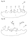
- FIG. 2A and 2B a cross-sectional view of an embodiment of an inventive embossed structure 200 for displaying four images is shown. Both the Figs. 2A and 2B show the same embossing structure 200 and differ only in the annotations given.
- the embossed structure 200 is formed in the surface of an object 1 and comprises a plurality of first grooves 10, five of which are depicted in Figs. 2A and 2B .
- Each groove 10 of the first plurality substantially forms a channel which extends into the paper plane.
- the embossed structure 200 further comprises a second plurality of grooves (not depicted) which extend transversely, preferably perpendicularly, to the grooves of the first plurality.
- the grooves of the second plurality thus run from left to right.
- the grooves of the second plurality may be formed identically to those of the first plurality.
- the embossed structure 200 may also be described as being made up of pyramids which each constitutes the elevation surrounded by two grooves of the first plurality and two grooves of the second plurality.
- Each groove 10 of the first plurality has a first side wall 20 and a second side wall 40. These side walls 20, 40 are inclined and may form a "V"-profile.
- the grooves of the second plurality are formed analogously to those of the first plurality, and thus also comprise two side walls, which will be referred to as a third side wall and a fourth side wall.
- the inventive embossed structure 200 displays four different images which can be separately observed dependent on the viewing direction. That means, from a first viewing direction 29 only the first image is visible, from a second viewing direction 49 only the second image is visible, and from a third and a fourth viewing direction (not shown) only a third and a fourth image is visible, respectively.
- the first viewing direction 29 may form an angle ⁇ 1 of 30° relative to a normal of the object's surface, wherein the angle ⁇ 1 is formed in a plane perpendicular to the object's surface and perpendicular to the grooves 10 of the first plurality.
- the second viewing direction 49 may form an angle ⁇ 2 of -30° relative to a normal of the object's surface, measured in the same plane as the angle ⁇ 1.
- the third and fourth viewing directions may form angles of +30° and -30°, respectively, which are measured in a plane perpendicular to the grooves of the second plurality and perpendicular to the object's surface.
- the grooves 10 of the first plurality are substantially formed like the grooves of the embossing structure 100 for displaying three images as described with reference to the Figs. 1A and 1B .
- the descriptions thereto are thus analogously applicable to the grooves 10 of the first plurality.
- a difference resides in that the grooves 10 of the first plurality do not require a bottom section with recesses being formed therein.
- the depicted embossing structure 200 of Figs. 2A and 2B thus does not display another (fifth) image in the top direction.
- recesses are formed in the first to fourth side walls.
- the recesses along the first side wall are formed corresponding to pixel values of the first image.
- the recesses along the second, third and fourth side walls are formed corresponding to pixel values of the second, third and fourth images, respectively.
- Each recess displays one pixel wherein the recess, in particular its size and shape, determines the amount of light that is scattered in the respective viewing direction.
- a pixel with maximum brightness corresponds to no recess being formed at the respective position along the respective side wall.
- a recess in one side wall mainly influences the amount of light scattered in the pertaining viewing direction, e.g. the first viewing direction, but does also slightly influence the amount of light scattered in the other viewing directions.
- recesses of the first the fourth side walls which recesses are adjacent to each other, are chosen such that the summed amount of light scattered from these four recesses in one viewing direction corresponds to the pixel value to be displayed.
- recesses in one side wall still mainly influence the scattering of light in one viewing direction, four different images can be simultaneously displayed in different viewing directions.
- the recesses are formed as steps 21, 22 and 41, 42.
- a step of the first side wall 20 comprises a ground surface 21 which is horizontal and thus parallel to a top surface 11 of the object 1 into which top surface 11 the inventive embossing structure 200 is formed.
- the step of the first side wall 20 further comprises an inclined surface 22 which is steeper than the surface of the side wall 20.
- a tilted surface may be provided between the ground surface 21 and the inclined surface 22 of one step.
- the slope of the tilted surface may be smaller than the slope of the inclined surface 22. That means, the tilted surface has an inclination angle, which is measured relative to an axis perpendicular to the object's surface, that is larger than the inclination angle of the inclined surface 22.
- An inclined entrance surface 12 is left at the first side wall 20 between the top surface 11 and the beginning of the recess, i.e. the inclined surface 22.
- a step in the second side wall 40 is built correspondingly and thus also comprises a ground surface 41 and an inclined surface 42 wherein an inclined entrance surface 13 is provided between the inclined surface 42 and the top surface 11.
- the third and fourth side walls which are not depicted, are provided with similar steps as recesses.
- the length of the steps may be varied. Additionally or alternatively, the concrete dimensions of different steps may be varied. In still another embodiment, either a recess or no recess is provided for displaying a dark or a bright pixel, respectively.
- the side walls 20, 40 have an inclination angle of 44.5° to a direction normal to the top surface 11. That means, the depicted angle "A" between the first side wall 20 and the second side wall 40 is 99°.
- the same values apply to the inclined entrance surfaces 12, 13.
- the inclined surfaces 22, 42 of the steps have an inclination angle "B" of 20° to a direction normal to the top surface 11.
- the depth "C" to a deepest point of one groove, i.e. to a center between the first and second side wall 20, 40, is equal to 0.1mm. This depth is measured starting from the top surface 11.
- the depth "D" to the ground surface 21, 41 of a step is equal to 0.075mm. This depth is again measured from the top surface 11.
- the width of the ground surfaces 21, 41 is 0.03mm.
- the distance "E" from one groove to the next parallel groove is equal to 0.3mm.
- the distance "F" from a center of one of the top surfaces 11 to a starting point of the ground surface 21, 41 of a step is equal to 0.12mm.
- the side walls 20, 40 of one groove may either form a sharp edge at the groove's center or an even bottom plane with a width of up to 0.02mm.
- the grooves of the second plurality comprising the third and fourth side walls and the corresponding steps therein are preferably also formed with the dimensions given above.
- the described embossed structures for displaying three images and for displaying four images advantageously provide an optimum contrast between the displayed images.
- the embossed structures are preferably used as security means, e.g. against counterfeiting. Objects such as coins, medals or smart cards provided with one of the inventive embossed structures are thus forgery-proof.
Landscapes
- Engineering & Computer Science (AREA)
- Manufacturing & Machinery (AREA)
- Business, Economics & Management (AREA)
- Accounting & Taxation (AREA)
- Finance (AREA)
- Credit Cards Or The Like (AREA)
- Machines For Manufacturing Corrugated Board In Mechanical Paper-Making Processes (AREA)
- Paper (AREA)
Claims (15)
- Reliefstruktur zum Darstellen verschiedener Bilder in verschiedenen Betrachtungsrichtungen (29, 39, 49),
wobei die Reliefstruktur eine Mehrzahl an Rillen (10) aufweist,
wobei jede Rille (10)- eine erste Seitenwand (20) zum Darstellen einer Reihe eines ersten Bildes in einer ersten Betrachtungsrichtung (29) und- eine zweite Seitenwand (40) zum Darstellen einer Reihe eines zweiten Bildes in einer zweiten Betrachtungsrichtung (49)aufweist,
wobei jede Rille (10) außerdem- einen Bodenbereich (30) zum Darstellen einer Reihe eines dritten Bildes in einer dritten Betrachtungsrichtung (39)aufweist,
wobei das erste, zweite und dritte Bild allein aus der ersten, zweiten beziehungsweise dritten Betrachtungsrichtung (29, 39, 49) klar sichtbar ist, während überlagerte Mischungen von zwei oder drei Bildern aus anderen Betrachtungswinkeln sichtbar sind,
dadurch gekennzeichnet,
dass der Bodenbereich (30), die erste Seitenwand (20) und die zweite Seitenwand (40) jeweils Vertiefungen (21, 22, 31, 32, 33, 41, 42) aufweisen, welche die Lichtmenge, die in die jeweilige Betrachtungsrichtung (29, 39, 49) gestreut wird, entsprechend Pixelwerten der drei Bilder bestimmen, wobei abhängig von einem darzustellenden Pixelwert eine Größe und/oder Form einer Vertiefung gewählt oder keine Vertiefung vorgesehen ist, und wobei jede Vertiefung einen Pixel darstellt. - Reliefstruktur nach Anspruch 1,
dadurch gekennzeichnet,
dass jede Reihe von jedem Bild aus einer Mehrzahl an Pixeln besteht, dass zum Darstellen der Pixel der jeweiligen Reihe entlang dem Bodenbereich (30) und der ersten und der zweiten Seitenwand (20, 40) jeweils eine Anzahl an Vertiefungen (21, 22, 31, 32, 33, 41, 42) vorgesehen ist, die der Anzahl an Pixeln von einer Reihe entspricht. - Reliefstruktur nach Anspruch 1 oder 2,
dadurch gekennzeichnet,
dass die Vertiefungen (21, 22, 31, 32, 33, 41, 42) von dem Bodenbereich (30) und den Seitenwänden (20, 40) jeweils als Stufen geformt sind. - Reliefstruktur nach Anspruch 3,
dadurch gekennzeichnet,
dass jede Stufe von einer der Seitenwände (20, 40) eine Grundfläche (21) und eine schräge Fläche (22) aufweist und
dass jede Stufe von dem Bodenbereich (30) eine Grundfläche (31) und zwei schräge Flächen (32, 33) aufweist. - Reliefstruktur nach einem der Ansprüche 1 bis 4,
dadurch gekennzeichnet,
dass der Abstand (d) zwischen zwei Rillen (10) zwischen 0,24 mm und 0,36 mm, vorzugsweise zwischen 0,27 mm und 0,33 mm, beträgt und besonders bevorzugt gleich 0,3 mm ist. - Reliefstruktur nach einem der Ansprüche 3 bis 5,
dadurch gekennzeichnet,
dass die Grundflächen (31) des Bodenbereichs (30) Breiten (e) zwischen 0,01 mm und 0,1 mm, bevorzugt zwischen 0,03 mm und 0,07 mm und besonders bevorzugt Breiten von 0,05 mm haben und
dass die Grundflächen (21, 41) der ersten und der zweiten Seitenwände (20, 40) Breiten (f) zwischen 0,015 mm und 0,035 mm, bevorzugt zwischen 0,020 mm und 0,030 mm und besonders bevorzugt Breiten von 0,025 mm haben. - Reliefstruktur nach einem der Ansprüche 3 bis 6,
dadurch gekennzeichnet,
dass die Tiefen (H2) zu den Grundflächen (31) der Bodenbereiche (30) zwischen 0,10 mm und 0,14 mm, bevorzugt zwischen 0,11 mm und 0,13 mm betragen und besonders bevorzugt gleich 0,12 mm sind und
dass die Tiefen (H1) zu den Grundflächen (21, 41) der ersten und der zweiten Seitenwände (20, 40) zwischen 0,05 mm und 0,09 mm, bevorzugt zwischen 0,06 mm und 0,08 mm betragen und besonders bevorzugt gleich 0,07 mm sind. - Reliefstruktur nach einem der Ansprüche 3 bis 7,
dadurch gekennzeichnet,
dass schräge Flächen (22, 42) der Seitenwände (20, 40) Neigungswinkel (a) zwischen 10° und 20°, bevorzugt zwischen 13° und 17° und besonders bevorzugt Neigungswinkel (a) von 15° haben und
dass die schrägen Flächen (22, 42) des Bodenbereichs (30) Neigungswinkel zwischen 15° und 25°, bevorzugt zwischen 17° und 12° und besonders bevorzugt Neigungswinkel von 20° haben. - Reliefstruktur nach einem der Ansprüche 3 bis 8,
dadurch gekennzeichnet,
dass zwischen jeder schrägen Fläche (22, 42) der Seitenwände (20, 40) und einer horizontalen Ebene (11) der Oberfläche des Objekts, in welcher die Reliefstruktur gebildet ist, jeweils eine schräge Eingangsfläche (23, 43) vorgesehen ist und
dass die schrägen Eingangsflächen (23, 43) Neigungswinkel zwischen 45° und 55°, bevorzugt zwischen 48° und 51° und besonders bevorzugt Neigungswinkel von 49,5° haben. - Reliefstruktur zum Darstellen verschiedener Bilder in verschiedenen Betrachtungsrichtungen (29, 49),
wobei die Reliefstruktur eine erste Mehrzahl an Rillen (10) in einer ersten Richtung aufweist,
wobei jede Rille (10) der ersten Mehrzahl- eine erste Seitenwand (20) zum Darstellen einer Reihe eines ersten Bildes in einer ersten Betrachtungsrichtung (29) und- eine zweite Seitenwand (40) zum Darstellen einer Reihe eines zweiten Bildes in einer zweiten Betrachtungsrichtung (49)aufweist, '
dadurch gekennzeichnet,
dass die Reliefstruktur außerdem eine zweite Mehrzahl an Rillen in einer zweiten Richtung aufweist, welche quer zu der ersten Richtung liegt,
dass die Rillen der zweiten Mehrzahl die Rillen (10) der ersten Mehrzahl schneiden,
dass jede Rille der zweiten Mehrzahl- eine dritte Seitenwand zum Darstellen einer Spalte eines dritten Bildes in einer dritten Betrachtungsrichtung und- eine vierte Seitenwand zum Darstellen einer Spalte eines vierten Bildes in einer vierten Betrachtungsrichtungaufweist,
dass jede der ersten bis vierten Seitenwand (20, 40) Vertiefungen (21, 22, 41, 42) aufweist, welche die Lichtmenge, die in die jeweilige Betrachtungsrichtung gestreut wird, entsprechend Pixelwerten der vier Bilder bestimmen, und wobei jede Vertiefung einen Pixel darstellt. - Reliefstruktur nach Anspruch 10,
dadurch gekennzeichnet,
dass jede Vertiefung (21, 22, 41, 42) als eine Stufe mit einer Grundfläche (21, 41) und einer schrägen Fläche (22, 42) gebildet ist. - Reliefstruktur nach Anspruch 11,
dadurch gekennzeichnet,
dass die schrägen Flächen (22, 42) Neigungswinkel (B) haben, die zwischen 15° und 25°, bevorzugt zwischen 18° und 22° liegen und besonders bevorzugt gleich 20° sind. - Reliefstruktur nach Anspruch 11 oder 12,
dadurch gekennzeichnet,
dass die Grundflächen (21, 41) Breiten zwischen 0,01 mm und 0,05 mm, bevorzugt zwischen 0,025 mm und 0,035 mm und besonders bevorzugt Breiten, die gleich 0,03 mm sind, haben. - Reliefstruktur nach einem der Ansprüche 11 bis 13,
dadurch gekennzeichnet,
dass die Tiefen (D) zu den Grundflächen (21, 41) zwischen 0,04 mm und 0,12 mm, bevorzugt zwischen 0,06 mm und 0,09 mm betragen und besonders bevorzugt gleich 0,075 mm sind und
dass die Tiefe (C) zu einer tiefsten Kante zwischen der ersten und der zweiten Seitenwand (20, 40) und die Tiefe (C) zu einer tiefsten Kante zwischen der dritten und der vierten Seitenwand jeweils zwischen 0,06 mm und 0,015 mm, bevorzugt zwischen 0,08 mm und 0,12 mm betragen und besonders bevorzugt gleich 0,1 mm sind. - Objekt mit mindestens einer Reliefstruktur nach einem der Ansprüche 1 bis 14.
Priority Applications (7)
| Application Number | Priority Date | Filing Date | Title |
|---|---|---|---|
| EP11006475.5A EP2554397B1 (de) | 2011-08-05 | 2011-08-05 | Prägestruktur |
| EA201490018A EA201490018A1 (ru) | 2011-08-05 | 2012-08-03 | Рельефная структура |
| CN201280038144.5A CN103717404A (zh) | 2011-08-05 | 2012-08-03 | 压印结构 |
| US14/236,407 US20140245911A1 (en) | 2011-08-05 | 2012-08-03 | Embossing Structure |
| PCT/EP2012/003327 WO2013020687A1 (en) | 2011-08-05 | 2012-08-03 | Embossing structure |
| DE202012007473U DE202012007473U1 (de) | 2011-08-05 | 2012-08-03 | Reliefstruktur |
| CA2841829A CA2841829A1 (en) | 2011-08-05 | 2012-08-03 | Embossing structure |
Applications Claiming Priority (1)
| Application Number | Priority Date | Filing Date | Title |
|---|---|---|---|
| EP11006475.5A EP2554397B1 (de) | 2011-08-05 | 2011-08-05 | Prägestruktur |
Publications (2)
| Publication Number | Publication Date |
|---|---|
| EP2554397A1 EP2554397A1 (de) | 2013-02-06 |
| EP2554397B1 true EP2554397B1 (de) | 2014-02-12 |
Family
ID=46614430
Family Applications (1)
| Application Number | Title | Priority Date | Filing Date |
|---|---|---|---|
| EP11006475.5A Not-in-force EP2554397B1 (de) | 2011-08-05 | 2011-08-05 | Prägestruktur |
Country Status (7)
| Country | Link |
|---|---|
| US (1) | US20140245911A1 (de) |
| EP (1) | EP2554397B1 (de) |
| CN (1) | CN103717404A (de) |
| CA (1) | CA2841829A1 (de) |
| DE (1) | DE202012007473U1 (de) |
| EA (1) | EA201490018A1 (de) |
| WO (1) | WO2013020687A1 (de) |
Families Citing this family (6)
| Publication number | Priority date | Publication date | Assignee | Title |
|---|---|---|---|---|
| EP2594149A1 (de) * | 2011-11-18 | 2013-05-22 | Fabrica Nacional De Moneda Y Timbre - Real Casa De La Moneda | Objekt mit einem Oberflächenbereich zur Anzeige einer Vielzahl von Bildern |
| DE102014011425A1 (de) * | 2014-07-31 | 2016-02-04 | Giesecke & Devrient Gmbh | Sicherheitselement zur Herstellung von Wertdokumenten |
| DE102015009786A1 (de) | 2015-07-27 | 2017-02-02 | Giesecke & Devrient Gmbh | Prägewerkzeug zur Herstellung eines Sicherheitselements mit einer optisch variablen Struktur |
| DE102015009983A1 (de) * | 2015-07-31 | 2017-02-02 | Giesecke & Devrient Gmbh | Taktile Strukturen auf Wertgegenständen |
| DE102018000243A1 (de) * | 2018-01-15 | 2019-07-18 | Giesecke+Devrient Currency Technology Gmbh | Sicherheitselement mit einer optisch variablen Struktur in einer Vertiefung |
| CN111775545B (zh) * | 2020-07-31 | 2022-09-09 | 彭亮 | 一种立体微结构烫印压印版设计制做方法 |
Family Cites Families (11)
| Publication number | Priority date | Publication date | Assignee | Title |
|---|---|---|---|---|
| US4124974A (en) * | 1977-04-26 | 1978-11-14 | Akzona Incorporated | Yarn twist arrangement |
| DK0650853T3 (da) | 1993-11-02 | 1997-11-03 | Nacional Moneda Timbre | Fremgangsmåde til frembringelse af to billeder på hårde overflader. |
| DE19541064A1 (de) * | 1995-11-03 | 1997-05-07 | Giesecke & Devrient Gmbh | Datenträger mit einem optisch variablen Element |
| US5722693A (en) * | 1996-10-03 | 1998-03-03 | Wicker; Kenneth M. | Embossed document protection methods and products |
| AUPQ119999A0 (en) * | 1999-06-25 | 1999-07-22 | Note Printing Australia Limited | Improved security documents |
| DE10044465A1 (de) * | 2000-09-08 | 2002-03-21 | Giesecke & Devrient Gmbh | Datenträger mit einem optisch variablen Element |
| DE10157534C1 (de) * | 2001-11-23 | 2003-05-15 | Ovd Kinegram Ag Zug | Sicherheitselement mit Beugungsstrukturen |
| WO2004030928A1 (en) * | 2002-10-07 | 2004-04-15 | Note Printing Australia Limited | Embossed optically variable devices |
| DE102006016342A1 (de) * | 2006-04-05 | 2007-10-11 | Giesecke & Devrient Gmbh | Sicherheitselement |
| NL2001466C2 (nl) * | 2008-04-10 | 2009-10-13 | Konink Nl Munt N V | Echtheidskenmerk en werkwijze voor het vervaardigen daarvan. |
| DE102009004128A1 (de) * | 2009-01-05 | 2010-07-08 | Giesecke & Devrient Gmbh | Sicherheitselement mit optisch variabler Struktur |
-
2011
- 2011-08-05 EP EP11006475.5A patent/EP2554397B1/de not_active Not-in-force
-
2012
- 2012-08-03 CA CA2841829A patent/CA2841829A1/en not_active Abandoned
- 2012-08-03 US US14/236,407 patent/US20140245911A1/en not_active Abandoned
- 2012-08-03 EA EA201490018A patent/EA201490018A1/ru unknown
- 2012-08-03 DE DE202012007473U patent/DE202012007473U1/de not_active Expired - Lifetime
- 2012-08-03 CN CN201280038144.5A patent/CN103717404A/zh active Pending
- 2012-08-03 WO PCT/EP2012/003327 patent/WO2013020687A1/en not_active Ceased
Also Published As
| Publication number | Publication date |
|---|---|
| EP2554397A1 (de) | 2013-02-06 |
| CN103717404A (zh) | 2014-04-09 |
| EA201490018A1 (ru) | 2014-06-30 |
| CA2841829A1 (en) | 2013-02-14 |
| WO2013020687A1 (en) | 2013-02-14 |
| US20140245911A1 (en) | 2014-09-04 |
| DE202012007473U1 (de) | 2012-08-29 |
Similar Documents
| Publication | Publication Date | Title |
|---|---|---|
| EP2554397B1 (de) | Prägestruktur | |
| EP3294566B1 (de) | Optisch variables sicherheitselement | |
| US9701150B2 (en) | Pixel mapping, arranging, and imaging for round and square-based lens arrays to achieve full volume 3D and multi-directional motion | |
| EP2192427B1 (de) | Indikationskörper und gekennzeichneter artikel | |
| EP2779857B1 (de) | Objekt mit einem oberflächenbereich zur anzeige einer vielzahl von bildern | |
| DE102005061749A1 (de) | Optisch variables Sicherheitselement und Verfahren zu seiner Herstellung | |
| DE10129939A1 (de) | Optisch variables Flächenmuster | |
| EP2655081B1 (de) | Optisch variables element, insbesondere sicherheitselement für einen datenträger | |
| DE102006006501A1 (de) | Sicherheitselement mit einer optisch variablen Struktur | |
| JP2009086648A (ja) | 表示体及びラベル付き物品 | |
| EP2029371B1 (de) | Refraktives durchsichtssicherheitselement | |
| EP1580020A1 (de) | Stichtiefdruckplatte | |
| WO2020052796A1 (de) | Sicherheitsdokument und verfahren zur herstellung eines sicherheitsdokuments | |
| WO2019219237A1 (de) | Optisch variables sicherheitselement mit reflektivem flächenbereich | |
| JP5721104B2 (ja) | 偽造防止担持体 | |
| JP5967658B2 (ja) | 特殊潜像画像形成体 | |
| EP1718182B1 (de) | Verfahren zum anbringen eines reliefbilds auf einer münze/wertmarke, auf diese weise erhaltene münze/wertmarke und dafür eingesetzte matrize | |
| GB2592719A (en) | Methods for designing and producing a security feature | |
| JP6217026B2 (ja) | 識別マーク形成体 | |
| NZ623924B2 (en) | Object comprising a region of its surface suitable for showing a plurality of images | |
| JP2002301855A (ja) | 特殊潜像模様形成体 | |
| HK1201032B (en) | Object comprising a region of its surface suitable for showing a plurality of images | |
| JP2013173250A (ja) | 複数潜像を有する画像形成体 | |
| HK1212454B (en) | Pixel mapping, arranging, and imaging for round and square-based micro lens arrays to achieve full volume 3d and multi-directional motion |
Legal Events
| Date | Code | Title | Description |
|---|---|---|---|
| PUAI | Public reference made under article 153(3) epc to a published international application that has entered the european phase |
Free format text: ORIGINAL CODE: 0009012 |
|
| 17P | Request for examination filed |
Effective date: 20120802 |
|
| AK | Designated contracting states |
Kind code of ref document: A1 Designated state(s): AL AT BE BG CH CY CZ DE DK EE ES FI FR GB GR HR HU IE IS IT LI LT LU LV MC MK MT NL NO PL PT RO RS SE SI SK SM TR |
|
| AX | Request for extension of the european patent |
Extension state: BA ME |
|
| RBV | Designated contracting states (corrected) |
Designated state(s): AL AT BE BG CH CY CZ DE DK EE ES FI FR GB GR HR HU IE IS IT LI LT LU LV MC MK MT NL NO PL PT RO RS SE SI SK SM TR |
|
| GRAP | Despatch of communication of intention to grant a patent |
Free format text: ORIGINAL CODE: EPIDOSNIGR1 |
|
| INTG | Intention to grant announced |
Effective date: 20130930 |
|
| GRAS | Grant fee paid |
Free format text: ORIGINAL CODE: EPIDOSNIGR3 |
|
| GRAA | (expected) grant |
Free format text: ORIGINAL CODE: 0009210 |
|
| AK | Designated contracting states |
Kind code of ref document: B1 Designated state(s): AL AT BE BG CH CY CZ DE DK EE ES FI FR GB GR HR HU IE IS IT LI LT LU LV MC MK MT NL NO PL PT RO RS SE SI SK SM TR |
|
| REG | Reference to a national code |
Ref country code: GB Ref legal event code: FG4D |
|
| REG | Reference to a national code |
Ref country code: CH Ref legal event code: EP |
|
| REG | Reference to a national code |
Ref country code: AT Ref legal event code: REF Ref document number: 651979 Country of ref document: AT Kind code of ref document: T Effective date: 20140215 |
|
| REG | Reference to a national code |
Ref country code: IE Ref legal event code: FG4D |
|
| REG | Reference to a national code |
Ref country code: DE Ref legal event code: R096 Ref document number: 602011004882 Country of ref document: DE Effective date: 20140327 |
|
| REG | Reference to a national code |
Ref country code: NL Ref legal event code: VDEP Effective date: 20140212 |
|
| REG | Reference to a national code |
Ref country code: AT Ref legal event code: MK05 Ref document number: 651979 Country of ref document: AT Kind code of ref document: T Effective date: 20140212 |
|
| REG | Reference to a national code |
Ref country code: LT Ref legal event code: MG4D |
|
| PG25 | Lapsed in a contracting state [announced via postgrant information from national office to epo] |
Ref country code: IS Free format text: LAPSE BECAUSE OF FAILURE TO SUBMIT A TRANSLATION OF THE DESCRIPTION OR TO PAY THE FEE WITHIN THE PRESCRIBED TIME-LIMIT Effective date: 20140612 Ref country code: NO Free format text: LAPSE BECAUSE OF FAILURE TO SUBMIT A TRANSLATION OF THE DESCRIPTION OR TO PAY THE FEE WITHIN THE PRESCRIBED TIME-LIMIT Effective date: 20140512 Ref country code: LT Free format text: LAPSE BECAUSE OF FAILURE TO SUBMIT A TRANSLATION OF THE DESCRIPTION OR TO PAY THE FEE WITHIN THE PRESCRIBED TIME-LIMIT Effective date: 20140212 |
|
| PG25 | Lapsed in a contracting state [announced via postgrant information from national office to epo] |
Ref country code: AT Free format text: LAPSE BECAUSE OF FAILURE TO SUBMIT A TRANSLATION OF THE DESCRIPTION OR TO PAY THE FEE WITHIN THE PRESCRIBED TIME-LIMIT Effective date: 20140212 Ref country code: NL Free format text: LAPSE BECAUSE OF FAILURE TO SUBMIT A TRANSLATION OF THE DESCRIPTION OR TO PAY THE FEE WITHIN THE PRESCRIBED TIME-LIMIT Effective date: 20140212 Ref country code: CY Free format text: LAPSE BECAUSE OF FAILURE TO SUBMIT A TRANSLATION OF THE DESCRIPTION OR TO PAY THE FEE WITHIN THE PRESCRIBED TIME-LIMIT Effective date: 20140212 Ref country code: FI Free format text: LAPSE BECAUSE OF FAILURE TO SUBMIT A TRANSLATION OF THE DESCRIPTION OR TO PAY THE FEE WITHIN THE PRESCRIBED TIME-LIMIT Effective date: 20140212 Ref country code: SE Free format text: LAPSE BECAUSE OF FAILURE TO SUBMIT A TRANSLATION OF THE DESCRIPTION OR TO PAY THE FEE WITHIN THE PRESCRIBED TIME-LIMIT Effective date: 20140212 Ref country code: ES Free format text: LAPSE BECAUSE OF FAILURE TO SUBMIT A TRANSLATION OF THE DESCRIPTION OR TO PAY THE FEE WITHIN THE PRESCRIBED TIME-LIMIT Effective date: 20140212 Ref country code: PT Free format text: LAPSE BECAUSE OF FAILURE TO SUBMIT A TRANSLATION OF THE DESCRIPTION OR TO PAY THE FEE WITHIN THE PRESCRIBED TIME-LIMIT Effective date: 20140612 |
|
| PG25 | Lapsed in a contracting state [announced via postgrant information from national office to epo] |
Ref country code: BE Free format text: LAPSE BECAUSE OF FAILURE TO SUBMIT A TRANSLATION OF THE DESCRIPTION OR TO PAY THE FEE WITHIN THE PRESCRIBED TIME-LIMIT Effective date: 20140212 Ref country code: HR Free format text: LAPSE BECAUSE OF FAILURE TO SUBMIT A TRANSLATION OF THE DESCRIPTION OR TO PAY THE FEE WITHIN THE PRESCRIBED TIME-LIMIT Effective date: 20140212 Ref country code: LV Free format text: LAPSE BECAUSE OF FAILURE TO SUBMIT A TRANSLATION OF THE DESCRIPTION OR TO PAY THE FEE WITHIN THE PRESCRIBED TIME-LIMIT Effective date: 20140212 Ref country code: RS Free format text: LAPSE BECAUSE OF FAILURE TO SUBMIT A TRANSLATION OF THE DESCRIPTION OR TO PAY THE FEE WITHIN THE PRESCRIBED TIME-LIMIT Effective date: 20140212 |
|
| PG25 | Lapsed in a contracting state [announced via postgrant information from national office to epo] |
Ref country code: EE Free format text: LAPSE BECAUSE OF FAILURE TO SUBMIT A TRANSLATION OF THE DESCRIPTION OR TO PAY THE FEE WITHIN THE PRESCRIBED TIME-LIMIT Effective date: 20140212 Ref country code: CZ Free format text: LAPSE BECAUSE OF FAILURE TO SUBMIT A TRANSLATION OF THE DESCRIPTION OR TO PAY THE FEE WITHIN THE PRESCRIBED TIME-LIMIT Effective date: 20140212 Ref country code: DK Free format text: LAPSE BECAUSE OF FAILURE TO SUBMIT A TRANSLATION OF THE DESCRIPTION OR TO PAY THE FEE WITHIN THE PRESCRIBED TIME-LIMIT Effective date: 20140212 Ref country code: RO Free format text: LAPSE BECAUSE OF FAILURE TO SUBMIT A TRANSLATION OF THE DESCRIPTION OR TO PAY THE FEE WITHIN THE PRESCRIBED TIME-LIMIT Effective date: 20140212 |
|
| PGFP | Annual fee paid to national office [announced via postgrant information from national office to epo] |
Ref country code: DE Payment date: 20140827 Year of fee payment: 4 |
|
| REG | Reference to a national code |
Ref country code: DE Ref legal event code: R026 Ref document number: 602011004882 Country of ref document: DE |
|
| PLBI | Opposition filed |
Free format text: ORIGINAL CODE: 0009260 |
|
| PG25 | Lapsed in a contracting state [announced via postgrant information from national office to epo] |
Ref country code: PL Free format text: LAPSE BECAUSE OF FAILURE TO SUBMIT A TRANSLATION OF THE DESCRIPTION OR TO PAY THE FEE WITHIN THE PRESCRIBED TIME-LIMIT Effective date: 20140212 Ref country code: SK Free format text: LAPSE BECAUSE OF FAILURE TO SUBMIT A TRANSLATION OF THE DESCRIPTION OR TO PAY THE FEE WITHIN THE PRESCRIBED TIME-LIMIT Effective date: 20140212 |
|
| PLAX | Notice of opposition and request to file observation + time limit sent |
Free format text: ORIGINAL CODE: EPIDOSNOBS2 |
|
| 26 | Opposition filed |
Opponent name: GIESECKE & DEVRIENT GMBH Effective date: 20141112 |
|
| REG | Reference to a national code |
Ref country code: DE Ref legal event code: R026 Ref document number: 602011004882 Country of ref document: DE Effective date: 20141112 |
|
| PG25 | Lapsed in a contracting state [announced via postgrant information from national office to epo] |
Ref country code: LU Free format text: LAPSE BECAUSE OF FAILURE TO SUBMIT A TRANSLATION OF THE DESCRIPTION OR TO PAY THE FEE WITHIN THE PRESCRIBED TIME-LIMIT Effective date: 20140805 Ref country code: MC Free format text: LAPSE BECAUSE OF FAILURE TO SUBMIT A TRANSLATION OF THE DESCRIPTION OR TO PAY THE FEE WITHIN THE PRESCRIBED TIME-LIMIT Effective date: 20140212 Ref country code: IT Free format text: LAPSE BECAUSE OF FAILURE TO SUBMIT A TRANSLATION OF THE DESCRIPTION OR TO PAY THE FEE WITHIN THE PRESCRIBED TIME-LIMIT Effective date: 20140212 |
|
| REG | Reference to a national code |
Ref country code: CH Ref legal event code: PL |
|
| PG25 | Lapsed in a contracting state [announced via postgrant information from national office to epo] |
Ref country code: LI Free format text: LAPSE BECAUSE OF NON-PAYMENT OF DUE FEES Effective date: 20140831 Ref country code: CH Free format text: LAPSE BECAUSE OF NON-PAYMENT OF DUE FEES Effective date: 20140831 |
|
| PLBB | Reply of patent proprietor to notice(s) of opposition received |
Free format text: ORIGINAL CODE: EPIDOSNOBS3 |
|
| REG | Reference to a national code |
Ref country code: IE Ref legal event code: MM4A |
|
| PG25 | Lapsed in a contracting state [announced via postgrant information from national office to epo] |
Ref country code: SI Free format text: LAPSE BECAUSE OF FAILURE TO SUBMIT A TRANSLATION OF THE DESCRIPTION OR TO PAY THE FEE WITHIN THE PRESCRIBED TIME-LIMIT Effective date: 20140212 |
|
| REG | Reference to a national code |
Ref country code: FR Ref legal event code: ST Effective date: 20150430 |
|
| PG25 | Lapsed in a contracting state [announced via postgrant information from national office to epo] |
Ref country code: FR Free format text: LAPSE BECAUSE OF NON-PAYMENT OF DUE FEES Effective date: 20140901 Ref country code: IE Free format text: LAPSE BECAUSE OF NON-PAYMENT OF DUE FEES Effective date: 20140805 |
|
| REG | Reference to a national code |
Ref country code: DE Ref legal event code: R119 Ref document number: 602011004882 Country of ref document: DE |
|
| GBPC | Gb: european patent ceased through non-payment of renewal fee |
Effective date: 20150805 |
|
| PG25 | Lapsed in a contracting state [announced via postgrant information from national office to epo] |
Ref country code: SM Free format text: LAPSE BECAUSE OF FAILURE TO SUBMIT A TRANSLATION OF THE DESCRIPTION OR TO PAY THE FEE WITHIN THE PRESCRIBED TIME-LIMIT Effective date: 20140212 |
|
| PG25 | Lapsed in a contracting state [announced via postgrant information from national office to epo] |
Ref country code: BG Free format text: LAPSE BECAUSE OF FAILURE TO SUBMIT A TRANSLATION OF THE DESCRIPTION OR TO PAY THE FEE WITHIN THE PRESCRIBED TIME-LIMIT Effective date: 20140212 Ref country code: GR Free format text: LAPSE BECAUSE OF FAILURE TO SUBMIT A TRANSLATION OF THE DESCRIPTION OR TO PAY THE FEE WITHIN THE PRESCRIBED TIME-LIMIT Effective date: 20140513 Ref country code: MT Free format text: LAPSE BECAUSE OF FAILURE TO SUBMIT A TRANSLATION OF THE DESCRIPTION OR TO PAY THE FEE WITHIN THE PRESCRIBED TIME-LIMIT Effective date: 20140212 |
|
| PG25 | Lapsed in a contracting state [announced via postgrant information from national office to epo] |
Ref country code: DE Free format text: LAPSE BECAUSE OF NON-PAYMENT OF DUE FEES Effective date: 20160301 Ref country code: TR Free format text: LAPSE BECAUSE OF FAILURE TO SUBMIT A TRANSLATION OF THE DESCRIPTION OR TO PAY THE FEE WITHIN THE PRESCRIBED TIME-LIMIT Effective date: 20140212 Ref country code: HU Free format text: LAPSE BECAUSE OF FAILURE TO SUBMIT A TRANSLATION OF THE DESCRIPTION OR TO PAY THE FEE WITHIN THE PRESCRIBED TIME-LIMIT; INVALID AB INITIO Effective date: 20110805 Ref country code: GB Free format text: LAPSE BECAUSE OF NON-PAYMENT OF DUE FEES Effective date: 20150805 |
|
| REG | Reference to a national code |
Ref country code: DE Ref legal event code: R100 Ref document number: 602011004882 Country of ref document: DE |
|
| PLCK | Communication despatched that opposition was rejected |
Free format text: ORIGINAL CODE: EPIDOSNREJ1 |
|
| PLBN | Opposition rejected |
Free format text: ORIGINAL CODE: 0009273 |
|
| STAA | Information on the status of an ep patent application or granted ep patent |
Free format text: STATUS: OPPOSITION REJECTED |
|
| 27O | Opposition rejected |
Effective date: 20170517 |
|
| REG | Reference to a national code |
Ref country code: DE Ref legal event code: R082 Ref document number: 602011004882 Country of ref document: DE Representative=s name: WUNDERLICH & HEIM PATENTANWAELTE PARTNERSCHAFT, DE |
|
| PG25 | Lapsed in a contracting state [announced via postgrant information from national office to epo] |
Ref country code: MK Free format text: LAPSE BECAUSE OF FAILURE TO SUBMIT A TRANSLATION OF THE DESCRIPTION OR TO PAY THE FEE WITHIN THE PRESCRIBED TIME-LIMIT Effective date: 20140212 |
|
| PG25 | Lapsed in a contracting state [announced via postgrant information from national office to epo] |
Ref country code: AL Free format text: LAPSE BECAUSE OF FAILURE TO SUBMIT A TRANSLATION OF THE DESCRIPTION OR TO PAY THE FEE WITHIN THE PRESCRIBED TIME-LIMIT Effective date: 20140212 |
|
| RIC2 | Information provided on ipc code assigned after grant |
Ipc: B42D 15/10 20181130AFI20111213BHEP |
|
| RIC2 | Information provided on ipc code assigned after grant |
Ipc: B42D 15/10 20060101AFI20111213BHEP |