EP2553370B1 - Vorrichtung zur tieftemperaturzerlegung von luft - Google Patents
Vorrichtung zur tieftemperaturzerlegung von luft Download PDFInfo
- Publication number
- EP2553370B1 EP2553370B1 EP11714930.2A EP11714930A EP2553370B1 EP 2553370 B1 EP2553370 B1 EP 2553370B1 EP 11714930 A EP11714930 A EP 11714930A EP 2553370 B1 EP2553370 B1 EP 2553370B1
- Authority
- EP
- European Patent Office
- Prior art keywords
- column
- mixing
- mixing column
- double
- cold box
- Prior art date
- Legal status (The legal status is an assumption and is not a legal conclusion. Google has not performed a legal analysis and makes no representation as to the accuracy of the status listed.)
- Active
Links
Images
Classifications
-
- F—MECHANICAL ENGINEERING; LIGHTING; HEATING; WEAPONS; BLASTING
- F25—REFRIGERATION OR COOLING; COMBINED HEATING AND REFRIGERATION SYSTEMS; HEAT PUMP SYSTEMS; MANUFACTURE OR STORAGE OF ICE; LIQUEFACTION SOLIDIFICATION OF GASES
- F25J—LIQUEFACTION, SOLIDIFICATION OR SEPARATION OF GASES OR GASEOUS OR LIQUEFIED GASEOUS MIXTURES BY PRESSURE AND COLD TREATMENT OR BY BRINGING THEM INTO THE SUPERCRITICAL STATE
- F25J3/00—Processes or apparatus for separating the constituents of gaseous or liquefied gaseous mixtures involving the use of liquefaction or solidification
- F25J3/02—Processes or apparatus for separating the constituents of gaseous or liquefied gaseous mixtures involving the use of liquefaction or solidification by rectification, i.e. by continuous interchange of heat and material between a vapour stream and a liquid stream
- F25J3/04—Processes or apparatus for separating the constituents of gaseous or liquefied gaseous mixtures involving the use of liquefaction or solidification by rectification, i.e. by continuous interchange of heat and material between a vapour stream and a liquid stream for air
- F25J3/0446—Processes or apparatus for separating the constituents of gaseous or liquefied gaseous mixtures involving the use of liquefaction or solidification by rectification, i.e. by continuous interchange of heat and material between a vapour stream and a liquid stream for air using the heat generated by mixing two different phases
- F25J3/04466—Processes or apparatus for separating the constituents of gaseous or liquefied gaseous mixtures involving the use of liquefaction or solidification by rectification, i.e. by continuous interchange of heat and material between a vapour stream and a liquid stream for air using the heat generated by mixing two different phases for producing oxygen as a mixing column overhead gas by mixing gaseous air feed and liquid oxygen
-
- F—MECHANICAL ENGINEERING; LIGHTING; HEATING; WEAPONS; BLASTING
- F25—REFRIGERATION OR COOLING; COMBINED HEATING AND REFRIGERATION SYSTEMS; HEAT PUMP SYSTEMS; MANUFACTURE OR STORAGE OF ICE; LIQUEFACTION SOLIDIFICATION OF GASES
- F25J—LIQUEFACTION, SOLIDIFICATION OR SEPARATION OF GASES OR GASEOUS OR LIQUEFIED GASEOUS MIXTURES BY PRESSURE AND COLD TREATMENT OR BY BRINGING THEM INTO THE SUPERCRITICAL STATE
- F25J3/00—Processes or apparatus for separating the constituents of gaseous or liquefied gaseous mixtures involving the use of liquefaction or solidification
- F25J3/02—Processes or apparatus for separating the constituents of gaseous or liquefied gaseous mixtures involving the use of liquefaction or solidification by rectification, i.e. by continuous interchange of heat and material between a vapour stream and a liquid stream
- F25J3/04—Processes or apparatus for separating the constituents of gaseous or liquefied gaseous mixtures involving the use of liquefaction or solidification by rectification, i.e. by continuous interchange of heat and material between a vapour stream and a liquid stream for air
- F25J3/04763—Start-up or control of the process; Details of the apparatus used
- F25J3/04866—Construction and layout of air fractionation equipments, e.g. valves, machines
- F25J3/04872—Vertical layout of cold equipments within in the cold box, e.g. columns, heat exchangers etc.
-
- F—MECHANICAL ENGINEERING; LIGHTING; HEATING; WEAPONS; BLASTING
- F25—REFRIGERATION OR COOLING; COMBINED HEATING AND REFRIGERATION SYSTEMS; HEAT PUMP SYSTEMS; MANUFACTURE OR STORAGE OF ICE; LIQUEFACTION SOLIDIFICATION OF GASES
- F25J—LIQUEFACTION, SOLIDIFICATION OR SEPARATION OF GASES OR GASEOUS OR LIQUEFIED GASEOUS MIXTURES BY PRESSURE AND COLD TREATMENT OR BY BRINGING THEM INTO THE SUPERCRITICAL STATE
- F25J3/00—Processes or apparatus for separating the constituents of gaseous or liquefied gaseous mixtures involving the use of liquefaction or solidification
- F25J3/02—Processes or apparatus for separating the constituents of gaseous or liquefied gaseous mixtures involving the use of liquefaction or solidification by rectification, i.e. by continuous interchange of heat and material between a vapour stream and a liquid stream
- F25J3/04—Processes or apparatus for separating the constituents of gaseous or liquefied gaseous mixtures involving the use of liquefaction or solidification by rectification, i.e. by continuous interchange of heat and material between a vapour stream and a liquid stream for air
- F25J3/04763—Start-up or control of the process; Details of the apparatus used
- F25J3/04866—Construction and layout of air fractionation equipments, e.g. valves, machines
- F25J3/0489—Modularity and arrangement of parts of the air fractionation unit, in particular of the cold box, e.g. pre-fabrication, assembling and erection, dimensions, horizontal layout "plot"
-
- F—MECHANICAL ENGINEERING; LIGHTING; HEATING; WEAPONS; BLASTING
- F25—REFRIGERATION OR COOLING; COMBINED HEATING AND REFRIGERATION SYSTEMS; HEAT PUMP SYSTEMS; MANUFACTURE OR STORAGE OF ICE; LIQUEFACTION SOLIDIFICATION OF GASES
- F25J—LIQUEFACTION, SOLIDIFICATION OR SEPARATION OF GASES OR GASEOUS OR LIQUEFIED GASEOUS MIXTURES BY PRESSURE AND COLD TREATMENT OR BY BRINGING THEM INTO THE SUPERCRITICAL STATE
- F25J3/00—Processes or apparatus for separating the constituents of gaseous or liquefied gaseous mixtures involving the use of liquefaction or solidification
- F25J3/02—Processes or apparatus for separating the constituents of gaseous or liquefied gaseous mixtures involving the use of liquefaction or solidification by rectification, i.e. by continuous interchange of heat and material between a vapour stream and a liquid stream
- F25J3/04—Processes or apparatus for separating the constituents of gaseous or liquefied gaseous mixtures involving the use of liquefaction or solidification by rectification, i.e. by continuous interchange of heat and material between a vapour stream and a liquid stream for air
- F25J3/04763—Start-up or control of the process; Details of the apparatus used
- F25J3/04866—Construction and layout of air fractionation equipments, e.g. valves, machines
- F25J3/04945—Details of internal structure; insulation and housing of the cold box
-
- F—MECHANICAL ENGINEERING; LIGHTING; HEATING; WEAPONS; BLASTING
- F25—REFRIGERATION OR COOLING; COMBINED HEATING AND REFRIGERATION SYSTEMS; HEAT PUMP SYSTEMS; MANUFACTURE OR STORAGE OF ICE; LIQUEFACTION SOLIDIFICATION OF GASES
- F25J—LIQUEFACTION, SOLIDIFICATION OR SEPARATION OF GASES OR GASEOUS OR LIQUEFIED GASEOUS MIXTURES BY PRESSURE AND COLD TREATMENT OR BY BRINGING THEM INTO THE SUPERCRITICAL STATE
- F25J2200/00—Processes or apparatus using separation by rectification
- F25J2200/04—Processes or apparatus using separation by rectification in a dual pressure main column system
Definitions
- the invention relates to a device for cryogenic separation of air according to the preamble of claim 1.
- a device for cryogenic separation of air according to the preamble of claim 1.
- Such a device is known from the document US-A-5,454,227 known.
- a coldbox is used for the thermal insulation of system components (see for example Hausen / Linde, Tiefftemperaturtechnik, 1985, especially pages 490 and 491 ).
- a "cold box” is here understood to mean an insulating casing which comprises a heat-insulated interior completely with outer walls; in the interior are arranged to be isolated plant parts, for example, one or more separation columns and / or heat exchangers.
- the insulating effect can be effected by appropriate design of the outer walls and / or by the filling of the gap between system parts and outer walls with an insulating material. In the latter variant, a powdery material such as perlite is preferably used.
- the invention has for its object to find an improved arrangement of the plant parts of a mixing column.
- the mixing column is fastened laterally to the double column via connecting elements, the mixing column being supported via the connecting elements on the double column.
- the mixing column can be attached to the high-pressure column and / or the low-pressure column, preferably it is connected exclusively to the low-pressure column.
- the connecting elements can be made by any known technique, for example as profiles, tubes or a combination of such elements. They are preferably made of the same material as the column walls of mixing column and double column or of a similar material and are connected, for example by welding with these column walls. At the point of contact between connecting elements and column wall patches or reinforcing plates are preferably used, which consist of the same material as the column wall.
- the connecting elements are preferably made of metal profiles, which are also formed of the same material. If the common coldbox is prefabricated in the factory and then transported completely to the construction site, the connection structure must in any case be so strong that it absorbs the forces from the horizontal transport. If required, a frame construction made of Cr-Ni steel can be additionally attached to the paving sheet, which reinforces the construction, but also causes a relatively large distance between the columns.
- the mixing column is preferably not supported from below, but in particular is connected exclusively by the connecting elements with the double column.
- One container for example, a column or a heat exchanger
- the cross sections of the two containers may overlap, but they may also be arranged completely offset from one another. Analogously, the term “superimposed” / "to understand each other".
- the main heat exchanger is arranged in the common cold box, so that the device has a total of only a single coldbox.
- the common cold box exceeds the permissible transport dimensions.
- the main heat exchanger is arranged in a further, separate from the common coldbox coldbox. The two cold boxes can be prefabricated in the workshop and then transported separately to the construction site.
- the device may also include a subcooling countercurrent.
- the subcooler countercurrent serves to subcool one or more liquids from one of the columns of the nitrogen-oxygen separation distillation column system or the mixing column in countercurrent to one or more cold gaseous streams, typically from the low pressure column to warm.
- a supercooling countercurrent liquid streams which are depressurized at boiling temperature from a higher pressure column (for example, the high pressure column) to a lower pressure column (for example, the low pressure column) are cooled to the boiling temperature as close as possible to the boiling temperature Pressure level corresponds.
- the amount of steam (Flash) is minimized during the relaxation from the higher to the lower pressure.
- the liquid Oxygen from the low pressure column is passed through the supercooling countercurrent upstream of the feed into the mixing column, this is heated inversely to get as close to the boiling point below the - regularly higher - pressure of the mixing column.
- the cold streams are warmed up with the thawing temperature from the lower pressure columns. Since these streams go into the main heat exchanger, the process air in the high-pressure column is also warmer, that is, it is closer to the tau temperature. The proportion of pre-liquefied air is minimized.
- the supercooling countercurrent can be arranged in a system with two cold boxes in the other coldbox.
- the supercooling countercurrent is placed in the common coldbox below the mixing column.
- the supercooling countercurrent is preferably arranged below the mixing column and is likewise connected to the double column, in particular to the high-pressure column.
- the connection to the double column is realized by similar connecting elements as in the mixing column.
- the upper end of the mixing column is arranged at least at the level of the upper end of the double column or at most by a fifth of the length of the double column below the upper end of the double column.
- the mixing column hangs as high as possible. Under certain conditions, it may even make sense to build the box higher than necessary for the double column in order to allow the transport of the bottom liquid from the mixing column in the low-pressure column without a pump.
- the additional steel construction costs can be outweighed by the saved pump costs. This is especially true for a method with injection of turbine air into the mixing column, as for example in US 5454227 or US 5490391 is shown, wherein the mixing column pressure is relatively low, in particular below the high pressure column pressure. At higher mixing column pressures (here the turbine air is usually blown into the low-pressure column), the mixing column can also be arranged lower.
- the upper ends of the mixing column and the double column are at the same geodetic height.
- a pump for transferring the bottoms liquid of the mixing column into the low-pressure column can be dispensed with even at a relatively low mixing column pressure.
- the vertical distance between the upper end of the double column and the upper end of the mixing column is preferably 0.4 m to 7.0 m.
- the mixing column is arranged in a corner of an imaginary rectangle 14, which is located in the horizontal, is oriented parallel to the walls of the common coldbox and also touches the outer walls of the mixing column and double column.
- the imaginary rectangle has at least one insulation distance of 450 mm.
- the base area of the common coldbox can be optimized.
- the narrow side of the cold box corresponds to the transport height, which must not exceed a maximum value for prefabricated cold boxes; the other side of the rectangle is the result and should otherwise be as small as possible.
- the mixing column is arranged so that the coldbox volume is minimized.
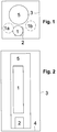
- FIG. 1 a mixing column 1 and a supercooling countercurrent 2 are arranged in a common coldbox 3.
- High-pressure column and low-pressure column of the distillation column system for nitrogen-oxygen separation are realized as a classic double column 5 and also housed in the common cold box 3.
- FIG. 2 shows the same arrangement in another view.
- FIG. 1 From the common coldbox 3 are in FIG. 1 only the lateral outer walls are shown. Details such as piping, valves and the interior of the apparatus 1, 2, 5 are not shown in the drawings.
- the space between the apparatus 1, 2, 5 and the outer wall of the common cold box 3 is filled with perlite.
- the underside of the common coldbox 3 is formed by a separate outer wall.
- the double column 5 is supported via a frame, not shown, on the bottom 4 of the common cold box 3.
- the mixing column 1 and the supercooling countercurrent are based on also not shown connecting elements on the double column 5 from. These fasteners are the same or similar to those in FIG. 3 executed connecting elements executed.
- a main heat exchanger is housed in the first embodiment in a separate further coldbox (in the Figures 1 and 2 not shown).
- the two dashed circles 1a and 1b in FIG. 1 represent two modifications of the first embodiment, in which the mixing column is arranged offset to the supercooling countercurrent 2. However, the mixing column is here also above the supercooling countercurrent arranged (analogous to FIG. 2 ).
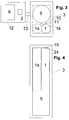
- the mixing column 1 and the double column 5 are arranged in the common coldbox 3.
- the subcooling countercurrent 2 is housed in another coldbox 12, together with the main heat exchanger 6.
- the main heat exchanger 6 is formed in the embodiment by a single heat exchanger block, in particular a plate heat exchanger. Alternatively, it may be formed by two or more blocks arranged horizontally next to each other and / or vertically one above the other.
- the supercooling countercurrent 2 may be arranged below the main heat exchanger 6.
- FIG. 4 shows the same common coldbox in different view.
- the space between the apparatus 1, 2, 5 and the outer wall of the common cold box 3 is filled with perlite.
- the underside of the common coldbox 3 is formed by a separate outer wall.
- the double column 5 is supported on the bottom 4 of the common cold box 3 via a frame (frame), not shown.
- the mixing column 1 is supported exclusively on the double column 5, specifically via at least two connecting elements which are respectively arranged in the upper and lower region of the mixing column 1.
- the connecting elements are dimensioned accordingly, if necessary, more than two connecting elements can be used.
- two pairs of connecting elements are used, which are each arranged in the upper and lower regions of the mixing column 1.
- the upper pair of these connecting elements 10, 11 is in FIG. 3 shown schematically.
- the upper element is preferably designed as a fixed point (welded or screwed on both columns), but the lower element is designed as a guide bearing in order to compensate for temperature stresses. This guide bearing fixes the horizontal arrangement and allows relative movement of mixing column and double column in the vertical direction.
- the roughly dashed line 14 in FIG. 3 represents a conceived rectangle, which has purely geometrical meaning, but to which no apparatus part corresponds.
- the space between the dashed line 14 and the outer wall 3 of the box here marks the minimum insulation distance in which no cold component may be located.
- the imaginary rectangle 14 is in the horizontal, is oriented parallel to the walls of the coldbox 3 and lies also on the outer walls of the two columns 1, 5 at.
- the mixing column 1 is preferably arranged in a corner of this rectangle 14, that is, it is touched by the rectangle 14 in two places. ( FIG. 4 For reasons of drawing, this aspect is not completely correct.)
- the fine dashed lines in the FIGS. 3 and 4 represent a modification of the first embodiment, in which the mixing column 1a is arranged differently.
- the upper end 24 of the mixing column is located 0.4 m below the upper end 15 of the double column 5 at a total height of the double column of about 35 m.
- the orientation of the two cold boxes to each other may be different from that shown in the drawings and depending on the spatial boundary conditions are arbitrary.
Description
- Die Erfindung betrifft eine Vorrichtung zur Tieftemperaturzerlegung von Luft gemäß dem Oberbegriff des Patentanspruchs 1. Eine solche Vorrichtung ist aus der Druckschrift
US-A-5 454 227 bekannt. - Luftzerlegungsverfahren mit Mischsäule sind seit den siebziger Jahren des vorigen Jahrhunderts bekannt (
DE 2204376 =US 4022030 ). Außerdem sind solche Verfahren inUS 5454227 ,US 5490391 ,DE 19803437 A1 ,DE 19951521 A1 ,EP 1139046 B1 (=US 2001052244 A1 ),EP 1284404 A1 (=US 6662595 B2 ),DE 10209421 A1 ,DE 10217093 A1 ,EP 1376037 B1 (=US 6776004 B2 ),EP 1387136 A1 undEP 1666824 A1 offenbart. Diese Schriften zeigen nur schematische Verfahrensdiagramme und enthalten keine Information über die räumliche Anordnung der Mischsäule in Bezug auf die übrigen Apparateteile. - Eine Coldbox dient zur thermischen Isolierung von Anlagenteilen (siehe zum Beispiel Hausen/Linde, Tieftemperaturtechnik, 1985, insbesondere Seiten 490 und 491). Unter einer "Coldbox" wird hier eine isolierende Umhüllung verstanden, die einen wärmeisolierten Innenraum vollständig mit Außenwänden umfasst; in dem Innenraum sind zu isolierenden Anlagenteile angeordnet, zum Beispiel ein oder mehrere Trennsäulen und/oder Wärmetauscher. Die isolierende Wirkung kann durch entsprechende Ausgestaltung der Außenwände und/oder durch die Füllung des Zwischenraums zwischen Anlagenteilen und Außenwänden mit einem Isoliermaterial bewirkt werden. Bei der letzteren Variante wird vorzugsweise ein pulverförmiges Material wie zum Beispiel Perlite verwendet.
- Aus
DE 19904526 A1 ist bekannt, Hochdrucksäule, Niederdrucksäule und Mischsäule nebeneinander auf dem Boden anzuordnen. InUS 6167723 wird ebenfalls empfohlen, die Mischsäule auf dem Boden aufzustellen, hier ist die Niederdrucksäule oberhalb der Mischsäule angeordnet, die Hochdrucksäule steht daneben. Auch inDE 19919587 A1 steht die Mischsäule auf dem Boden; die Doppelsäule aus Hochdrucksäule und Niederdrucksäule ist oberhalb der Mischsäule aufgebaut. - Der Erfindung liegt die Aufgabe zugrunde, eine verbesserte Anordnung der Anlagenteile einer Mischsäule zu finden.
- Diese Aufgabe wird dadurch gelöst, dass die Mischsäule über Verbindungselemente seitlich an der Doppelsäule befestigt ist, wobei die Mischsäule sich über die Verbindungselemente an der Doppelsäule abstützt. Grundsätzlich kann die Mischsäule an der Hochdrucksäule und/oder der Niederdrucksäule angeheftet sein, vorzugsweise ist sie ausschließlich mit der Niederdrucksäule verbunden.
- Durch diese Befestigungsmethode ist es - im Unterschied zu der konventionellen Anordnung der Mischsäule auf dem Boden oder auf einem auf dem Boden stehenden Gestell - möglich, die geodätische Höhe, auf der die Mischsäule angeordnet ist, frei zu wählen. Hierdurch kann der Transport von Flüssigkeiten in der Anlage optimiert werden. In vielen Fällen ist es möglich, Pumpen mit kleinerer Leistung einzubauen oder sogar auf eine oder mehrere Pumpen zu verzichten. Dies gilt insbesondere bei relativ niedrigem Druck in der Mischsäule beziehungsweise im Sauerstoffgas-Produktgas aus der Mischsäule.
- Die Verbindungselemente können mit jeder bekannten Technik ausgeführt werden, beispielsweise als Profile, Rohre oder eine Kombination derartiger Elemente. Sie bestehen vorzugsweise aus dem gleichen Material wie die Kolonnenwände von Mischsäule und Doppelsäule oder aus einem ähnlichen Material und werden beispielsweise durch Schweißen mit diesen Kolonnenwänden verbunden. An der Berührungsstelle zwischen Verbindungselementen und Kolonnenwand werden vorzugsweise Pflaster beziehungsweise Verstärkungsbleche eingesetzt, die aus dem gleichen Material wie die Kolonnenwand bestehen. Die Verbindungselemente bestehen vorzugsweise aus Metallprofilen, die ebenfalls aus dem gleichen Material gebildet sind. Falls die gemeinsame Coldbox in der Fabrik vorgefertigt und anschließend komplett zur Baustelle transportiert wird, muss die Verbindungskonstruktion jedenfalls so stark sein, dass sie die Kräfte aus dem horizontalen Transport aufnimmt. Bei Bedarf kann am Pflasterblech zusätzlich eine Rahmenkonstruktion aus Cr-Ni-Stahl angebracht werden, welche die Konstruktion verstärkt, aber auch einen relativ großen Abstand zwischen den Kolonnen verursacht.
- Grundsätzlich ist es dabei möglich, die Mischsäule zusätzlich von unten abzustützen, etwa auf einem unterhalb der Mischsäule angeordneten weiteren Apparateteil. Im Rahmen der Erfindung wird die Mischsäule jedoch vorzugsweise nicht von unten abgestützt, sondern insbesondere ausschließlich durch die Verbindungselemente mit der Doppelsäule verbunden.
- Alle Angaben zur räumlichen Orientierung beziehen sich hier auf Ausrichtung der Vorrichtung während des Betriebs der Kolonnen.
- Ein Behälter (zum Beispiel eine Säule oder ein Wärmetauscher) befindet sich "oberhalb" (beziehungsweise "unterhalb") eines anderen Behälters, wenn sich seine Unterkante (Oberkante) auf höherem (niedrigerem) geodätischen Niveau als die Oberkante (Unterkante) des anderen Behälters befindet. Dabei kann, muss aber nicht eine vertikale Linie existieren, die durch beide Behälter hindurchgeht. In der Projektion auf eine horizontale Ebene können sich die Querschnitte der beiden Behälter überschneiden, sie können aber auch vollständig versetzt zueinander angeordnet sein. Analog ist der Begriff "übereinander"/"untereinander" zu verstehen.
- Es ist möglich, auch den Hauptwärmetauscher in der gemeinsamen Coldbox anzuordnen, sodass die Vorrichtung insgesamt nur eine einzige Coldbox aufweist. Hierbei besteht jedoch die Gefahr, dass die gemeinsame Coldbox die zulässigen Transportmaße überschreitet. In einer weiteren Ausgestaltung der Erfindung wird deshalb der Hauptwärmetauscher in einer weiteren, von der gemeinsamen Coldbox getrennten Coldbox angeordnet. Die beiden Coldboxen können in der Werkstatt vorgefertigt und anschließend getrennt voneinander zur Baustelle transportiert werden.
- Die Vorrichtung kann außerdem einen Unterkühlungs-Gegenströmer aufweisen. Der Unterkühlungs-Gegenströmer dient dazu, eine oder mehrere Flüssigkeiten aus einer der Säulen des Destilliersäulen-Systems zur Stickstoff-Sauerstoff-Trennung oder der Mischsäule im Gegenstrom zu einem oder mehreren kalten gasförmigen Strömen, die in der Regel aus der Niederdrucksäule kommen, zu unterkühlen oder anzuwärmen. Insbesondere werden in einem Unterkühlungs-Gegenströmer flüssige Ströme, die mit Siedetemperatur aus einer Säule mit höheren Druck (zum Beispiel der Hochdrucksäule) in eine Säule mit niedrigerem Druck (zum Beispiel die Niederdrucksäule) entspannt werden, möglichst bis zu der Siedetemperatur abgekühlt, die dem niedrigeren Druckniveau entspricht. Dabei wird die Dampfmenge (Flash) bei der Entspannung vom höheren auf den niedrigeren Druck minimiert. Wenn der flüssige Sauerstoff aus der Niederdrucksäule vor der Einspeisung in die Mischsäule durch den Unterkühlungs-Gegenströmer geführt wird, wird dieser umgekehrt angewärmt, um möglichst nahe an den Siedepunkt unter dem - regelmäßig höheren - Druck der Mischsäule zu gelangen. Im Gegenzug dazu werden die kalten Ströme mit der Tautemperatur aus den Säulen mit dem niedrigeren Druck angewärmt. Da diese Ströme in den Hauptwärmetauscher gehen, wird die Prozessluft in die Hochdrucksäule ebenfalls wärmer, das heißt sie ist der Tautemperatur näher. Der Anteil der vorverflüssigten Luft wird minimiert.
- Der Unterkühlungs-Gegenströmer kann bei einer Anlage mit zwei Coldboxen in der weiteren Coldbox angeordnet sein.
- Alternativ wird der Unterkühlungs-Gegenströmer in der gemeinsamen Coldbox unterhalb der Mischsäule angeordnet. Dabei wird der Unterkühlungs-Gegenströmer vorzugsweise unterhalb der Mischsäule angeordnet und ist ebenfalls mit der Doppelsäule, insbesondere mit der Hochdrucksäule, verbunden. Die Verbindung zur Doppelsäule wird durch ähnliche Verbindungselemente wie bei der Mischsäule realisiert.
- Gemäß einer weiteren Ausgestaltung der Erfindung ist das obere Ende der Mischsäule mindestens auf der Höhe des oberen Endes der Doppelsäule oder höchstens um ein Fünftel der Länge der Doppelsäule unterhalb des oberen Endes der Doppelsäule angeordnet. Vorzugsweise hängt die Mischsäule so weit oben wie möglich. Unter bestimmten Bedingungen kann es sogar sinnvoll sein, die Box höher als für die Doppelsäule notwendig zu bauen, um den Transport der Sumpfflüssigkeit aus der Mischsäule in die Niederdrucksäule ohne Pumpe zu ermöglichen. Die zusätzlichen Stahlbaukosten können dabei durch die eingesparten Pumpenkosten überwogen werden. Dies gilt insbesondere für ein Verfahren mit Einblasung von Turbinenluft in die Mischsäule, wie es beispielsweise in
US 5454227 oderUS 5490391 gezeigt ist, wobei der Mischsäulendruck relativ niedrig ist, insbesondere unterhalb des Hochdrucksäulendrucks. Bei höheren Mischsäulendrücken (hier wird die Turbinenluft meistens in die Niederdrucksäule eingeblasen), kann man die Mischsäule auch niedriger anordnen. - Beispielsweise befinden sich die oberen Enden der Mischsäule und der Doppelsäule auf der gleichen geodätischen Höhe. Durch diese relativ hohe Position der Mischsäule kann auch bei relativ niedrigem Mischsäulendruck auf eine Pumpe zur Überleitung der Sumpfflüssigkeit der Mischsäule in die Niederdrucksäule verzichtet werden.
- Wenn das obere Ende der Mischsäule oberhalb oder unterhalb der des oberen Endes der Doppelsäule angeordnet ist, liegt der vertikale Abstand zwischen dem oberen Ende der Doppelsäule und dem oberen Ende der Mischsäule vorzugsweise bei 0,4 m bis 7,0 m.
- Besonders günstig ist eine Anordnung, bei der die Mischsäule in einer Ecke eines gedachten Rechtecks 14 angeordnet ist, das sich in der Horizontalen befindet, parallel zu den Wänden der gemeinsamen Coldbox orientiert ist und außerdem die Außenwände von Mischsäule und Doppelsäule berührt. Gegenüber den Außenwänden der gemeinsamen Coldbox weist das gedachte Rechteck mindestens einen Isolierabstand von 450 mm auf. Dadurch kann die Grundfläche der gemeinsamen Coldbox optimiert werden. Dabei ist zu beachten, dass die Schmalseite der Coldbox der Transporthöhe entspricht, die bei vorgefertigten Coldboxen einen Höchstwert nicht überschreiten darf; die andere Seite des Rechtecks ergibt sich daraus und sollte ansonsten möglichst klein sein. Für den Fall der Baustellenmontage wird die Mischsäule so angeordnet, dass das Coldboxvolumen minimiert wird.
- Die Erfindung sowie weitere Einzelheiten der Erfindung werden im Folgenden anhand von in den Zeichnungen schematisch dargestellten Ausführungsbeispielen näher erläutert. Hierbei zeigen:
- Figur 1
- ein erstes Ausführungsbeispiel der Erfindung mit Anordnung von Mischsäule und Unterkühlungs-Gegenströmer übereinander in horizontaler Querschnittsdarstellung,
- Figur 2
- das erste Ausführungsbeispiel in vertikaler Querschnittsdarstellung,
- Figur 3
- ein zweites Ausführungsbeispiel der Erfindung ohne Unterkühlungs-Gegenströmer in der gemeinsamen Coldbox und
- Figur 4
- die gemeinsame Coldbox des zweiten Ausführungsbeispiels in vertikaler Querschnittsdarstellung.
- In dem Beispiel von
Figur 1 sind eine Mischsäule 1 und ein Unterkühlungs-Gegenströmer 2 in einer gemeinsamen Coldbox 3 angeordnet. Hochdrucksäule und Niederdrucksäule des Destilliersäulen-Systems zur Stickstoff-Sauerstoff-Trennung sind als klassische Doppelsäule 5 realisiert und ebenfalls in der gemeinsamen Coldbox 3 untergebracht.Figur 2 zeigt dieselbe Anordnung in anderer Ansicht. - Von der gemeinsamen Coldbox 3 sind in
Figur 1 nur die seitlichen Außenwände dargestellt. Details wie Rohrleitungen, Ventile und das Innere der Apparate 1, 2, 5 sind in den Zeichnungen nicht gezeigt. Der Zwischenraum zwischen den Apparaten 1, 2, 5 und der Außenwand der gemeinsamen Coldbox 3 ist mit Perlite gefüllt. Die Unterseite der gemeinsamen Coldbox 3 wird durch eine separate Außenwand gebildet. Die Doppelsäule 5 ist über ein nicht dargestelltes Gestell auf dem Boden 4 der gemeinsamen Coldbox 3 abgestützt. Die Mischsäule 1 und der Unterkühlungs-Gegenströmer stützen sich über ebenfalls nicht dargestellte Verbindungselemente an der Doppelsäule 5 ab. Diese Verbindungselemente sind gleich oder ähnlich wie die inFigur 3 dargestellten Verbindungselemente ausgeführt. - Ein Hauptwärmetauscher ist bei dem ersten Ausführungsbeispiel in einer separaten weiteren Coldbox untergebracht (in den
Figuren 1 und 2 nicht dargestellt). - Die beiden gestrichelten Kreise 1a und 1b in
Figur 1 stellen zwei Abwandlungen des ersten Ausführungsbeispiels dar, bei der die Mischsäule versetzt zum Unterkühlungs-Gegenströmer 2 angeordnet ist. Die Mischsäule ist jedoch auch hier oberhalb des Unterkühlungs-Gegenströmers angeordnet (analog zuFigur 2 ). - Auch in dem Beispiel von
Figur 3 sind die Mischsäule 1 und die Doppelsäule 5 in der gemeinsamen Coldbox 3 angeordnet. Der Unterkühlungs-Gegenströmer 2 ist dagegen in einer weiteren Coldbox 12 untergebracht, zusammen mit dem Hauptwärmetauscher 6. Auch hier sind Details wie Rohrleitungen, Ventile und das Innere der Apparate 1, 2, 5, 6 nicht gezeigt. Der Hauptwärmetauscher 6 wird in dem Ausführungsbeispiel durch einen einzigen Wärmetauscher-Block gebildet, insbesondere einen Plattenwärmetauscher. Alternativ kann er durch zwei oder mehr horizontal nebeneinander und/oder vertikal übereinander angeordnete Blöcke gebildet werden. Alternativ zu der Darstellung inFigur 3 kann der Unterkühlungs-Gegenströmer 2 unterhalb des Hauptwärmetauschers 6 angeordnet sein. -
Figur 4 zeigt dieselbe gemeinsame Coldbox in anderer Ansicht. - Der Zwischenraum zwischen den Apparaten 1, 2, 5 und der Außenwand der gemeinsamen Coldbox 3 ist mit Perlite gefüllt. Die Unterseite der gemeinsamen Coldbox 3 wird durch eine separate Außenwand gebildet. Die Doppelsäule 5 ist über ein nicht dargestelltes Gestell (Standzarge) auf dem Boden 4 der gemeinsamen Coldbox 3 abgestützt. Die Mischsäule 1 stützt sich ausschließlich an der Doppelsäule 5 ab, und zwar über vorzugsweise über jeweils mindestens zwei Verbindungselemente die jeweils im oberen und unteren Bereich der Mischsäule 1 angeordnet sind. Die Verbindungselemente sind entsprechend dimensioniert, gegebenenfalls können auch mehr als zwei Verbindungselemente verwendet werden. In dem dargestellten Ausführungsbeispiel werden zwei Paare von Verbindungselementen verwendet, die jeweils im oberen und unteren Bereich der Mischsäule 1 angeordnet sind. Das obere Paar dieser Verbindungselemente 10, 11 ist in
Figur 3 schematisch dargestellt. Vorzugsweise ist das obere Element als Festpunkt (an beiden Säulen geschweißt oder geschraubt) ausgeführt, das untere aber als Führungslager, um Temperaturspannungen zu kompensieren. Dieses Führungslager fixiert die horizontale Anordnung und ermöglicht eine relative Bewegung von Mischsäule und Doppelsäule in vertikaler Richtung. - Die grob gestrichelte Linie 14 in
Figur 3 stellt ein gedachtes Rechteck dar, das rein geometrische Bedeutung hat, dem aber kein Apparateteil entspricht. (Der Raum zwischen der gestrichelten Linie 14 und der Außenwand 3 der Box markiert hier den minimalen Isolierabstand in dem sich kein kaltes Bauteil befinden darf.) Das gedachte Rechteck 14 befindet sich in der Horizontalen, ist parallel zu den Wänden der Coldbox 3 orientiert und liegt außerdem an den Außenwänden der beiden Kolonnen 1, 5 an. Im Rahmen der Erfindung ist die Mischsäule 1 vorzugsweise in einer Ecke dieses Rechtecks 14 angeordnet, das heißt sie wird an zwei Stellen von dem Rechteck 14 berührt. (Figur 4 stellt diesen Aspekt aus zeichnerischen Gründen nicht vollständig korrekt dar.) - Die fein gestrichelten Linien in den
Figuren 3 und 4 stellen eine Abwandlung des ersten Ausführungsbeispiels dar, bei der die Mischsäule 1a abweichend angeordnet ist. - In dem Ausführungsbeispiel der
Figuren 3 und 4 ist das obere Ende 24 der Mischsäule 0,4 m unterhalb des oberen Endes 15 der Doppelsäule 5 angeordnet bei einer Gesamthöhe der Doppelsäule von etwa 35 m. - Die Orientierung der beiden Coldboxen zueinander kann abweichend von der in den Zeichnungen dargestellten sein und je nach räumlichen Randbedingungen beliebig gewählt werden.
Claims (7)
- Vorrichtung zur Tieftemperaturzerlegung von Luft mit einem Hauptwärmetauscher (6), mit einem Destilliersäulen-System zur Stickstoff-Sauerstoff-Trennung (5), das eine Doppelsäule (5) aufweist, die eine Hochdrucksäule und eine Niederdrucksäule enthält, mit einer Mischsäule (1) und mit Mitteln zum Einleiten von Einsatzluft über den Hauptwärmetauscher (6) in die Hochdrucksäule und in die Mischsäule, mit einer Flüssigsauerstoffleitung zum Einleiten von flüssigem Sauerstoff aus der Niederdrucksäule in den oberen Bereich der Mischsäule (1) und mit einer Sauerstoffproduktleitung zum Abziehen von Sauerstoffgas aus dem oberen Bereich der Mischsäule (1) durch den Hauptwärmetauscher (6), wobei die Mischsäule (1) seitlich neben der Doppelsäule (5) angeordnet ist, dadurch gekennzeichnet, dass die Mischsäule (1) und die Doppelsäule (5) in einer gemeinsamen Coldbox (3) angeordnet sind und dass die Mischsäule (1) über Verbindungselemente (10, 11) seitlich an der Doppelsäule (5) befestigt ist, wobei die Mischsäule (1) sich über die Verbindungselemente (10, 11) an der Doppelsäule 5 abstützt.
- Vorrichtung nach Anspruch 1, dadurch gekennzeichnet, dass die Mischsäule (1) nicht von unten abgestützt ist.
- Vorrichtung nach Anspruch 1 oder 2, dadurch gekennzeichnet, dass der Hauptwärmetauscher (6) in einer weiteren, von der gemeinsamen Coldbox (3) getrennten Coldbox (12) angeordnet ist.
- Vorrichtung nach einem der Anspruch 3, gekennzeichnet durch einen Unterkühlungs-Gegenströmer (2), der in der weiteren Coldbox (12) angeordnet ist.
- Vorrichtung nach einem der Ansprüche 1 bis 3, gekennzeichnet durch einen Unterkühlungs-Gegenströmer (2), der in der gemeinsamen Coldbox (3) unterhalb der Mischsäule (1) angeordnet ist.
- Vorrichtung nach einem der Ansprüche 1 bis 5, dadurch gekennzeichnet, dass das obere Ende (24) der Mischsäule (1) mindestens auf der Höhe des oberen Endes (15) der Doppelsäule (5) oder höchstens um ein Fünftel der Länge der Doppelsäule (5) unterhalb des oberen Endes der Doppelsäule (5) angeordnet ist.
- Vorrichtung nach einem der Ansprüche 1 bis 6, dadurch gekennzeichnet, dass die Mischsäule (1) in einer Ecke eines Rechtecks (14) angeordnet ist, das in der Horizontalen liegt, parallel zu den Wänden der gemeinsamen Coldbox (3) orientiert ist und die Außenwände der von Mischsäule (1) und Doppelsäule (5) berührt.
Priority Applications (1)
| Application Number | Priority Date | Filing Date | Title |
|---|---|---|---|
| PL11714930T PL2553370T3 (pl) | 2010-03-26 | 2011-03-25 | Urządzenie do niskotemperaturowej separacji powietrza |
Applications Claiming Priority (3)
| Application Number | Priority Date | Filing Date | Title |
|---|---|---|---|
| DE102010012920A DE102010012920A1 (de) | 2010-03-26 | 2010-03-26 | Vorrichtung zur Tieftemperaturzerlegung von Luft |
| PCT/EP2011/001004 WO2011116871A2 (de) | 2010-03-26 | 2011-03-01 | Vorrichtung zur tieftemperaturzerlegung von luft |
| PCT/EP2011/001509 WO2011116981A2 (de) | 2010-03-26 | 2011-03-25 | Vorrichtung zur tieftemperaturzerlegung von luft |
Publications (2)
| Publication Number | Publication Date |
|---|---|
| EP2553370A2 EP2553370A2 (de) | 2013-02-06 |
| EP2553370B1 true EP2553370B1 (de) | 2019-05-15 |
Family
ID=46245691
Family Applications (1)
| Application Number | Title | Priority Date | Filing Date |
|---|---|---|---|
| EP11714930.2A Active EP2553370B1 (de) | 2010-03-26 | 2011-03-25 | Vorrichtung zur tieftemperaturzerlegung von luft |
Country Status (3)
| Country | Link |
|---|---|
| EP (1) | EP2553370B1 (de) |
| PL (1) | PL2553370T3 (de) |
| WO (1) | WO2011116981A2 (de) |
Families Citing this family (6)
| Publication number | Priority date | Publication date | Assignee | Title |
|---|---|---|---|---|
| JP5817327B2 (ja) * | 2010-09-29 | 2015-11-18 | 東ソー株式会社 | 酸化物焼結体、その製造方法、それを用いて得られる酸化物透明導電膜及び太陽電池 |
| DE102011015233A1 (de) | 2011-03-25 | 2012-09-27 | Linde Ag | Vorrichtung zur Tieftemperaturzerlegung von Luft |
| DE102012006484A1 (de) * | 2012-03-29 | 2013-10-02 | Linde Aktiengesellschaft | Transportables Paket mit einer Coldbox und Verfahren zum Herstellen einer Tieftemperatur-Luftzerlegungsanlage |
| US10145514B2 (en) | 2013-11-18 | 2018-12-04 | Man Energy Solutions Se | Cold-box system and method for power management aboard ships |
| FR3119884B1 (fr) * | 2021-02-18 | 2022-12-30 | Air Liquide | Procédé de séparation d’air par distillation cryogénique |
| FR3123113B1 (fr) * | 2021-05-19 | 2023-06-09 | Air Liquide | Colonne de distillation et méthode de transportation d’une colonne de distillation |
Citations (1)
| Publication number | Priority date | Publication date | Assignee | Title |
|---|---|---|---|---|
| WO2011116871A2 (de) * | 2010-03-26 | 2011-09-29 | Linde Aktiengesellschaft | Vorrichtung zur tieftemperaturzerlegung von luft |
Family Cites Families (19)
| Publication number | Priority date | Publication date | Assignee | Title |
|---|---|---|---|---|
| US4022030A (en) | 1971-02-01 | 1977-05-10 | L'air Liquide, Societe Anonyme Pour L'etude Et L'exploitation Des Procedes Georges Claude | Thermal cycle for the compression of a fluid by the expansion of another fluid |
| US5454227A (en) | 1994-08-17 | 1995-10-03 | The Boc Group, Inc. | Air separation method and apparatus |
| US5490391A (en) | 1994-08-25 | 1996-02-13 | The Boc Group, Inc. | Method and apparatus for producing oxygen |
| DE19803437A1 (de) | 1998-01-29 | 1999-03-18 | Linde Ag | Verfahren und Vorrichtung zur Gewinnung eines Druckprodukts durch Tieftemperaturzerlegung von Luft |
| FR2774752B1 (fr) | 1998-02-06 | 2000-06-16 | Air Liquide | Installation de distillation d'air et boite froide correspondante |
| FR2778233B1 (fr) | 1998-04-30 | 2000-06-02 | Air Liquide | Installation de distillation d'air et boite froide correspondante |
| FR2778234B1 (fr) | 1998-04-30 | 2000-06-02 | Air Liquide | Installation de distillation d'air et boite froide correspondante |
| US6134915A (en) * | 1999-03-30 | 2000-10-24 | The Boc Group, Inc. | Distillation column arrangement for air separation plant |
| DE19951521A1 (de) | 1999-10-26 | 2001-05-03 | Linde Ag | Verfahren und Vorrichtung zur Gewinnung eines Druckprodukts durch Tieftemperaturzerlegung von Luft |
| DE10015602A1 (de) | 2000-03-29 | 2001-10-04 | Linde Ag | Verfahren und Vorrichtung zur Gewinnung eines Druckprodukts durch Tieftemperaturzerlegung von Luft |
| DE10139727A1 (de) | 2001-08-13 | 2003-02-27 | Linde Ag | Verfahren und Vorrichtung zur Gewinnung eines Druckprodukts durch Tieftemperaturzerlegung von Luft |
| DE10161584A1 (de) * | 2001-12-14 | 2003-06-26 | Linde Ag | Vorrichtung und Verfahren zur Erzeugung gasförmigen Sauerstoffs unter erhöhtem Druck |
| DE10209421A1 (de) | 2002-03-05 | 2003-04-03 | Linde Ag | Verfahren und Vorrichtung zur Gewinnung eines Druckprodukts durch Tieftemperaturzerlegung von Luft |
| DE10217093A1 (de) | 2002-04-17 | 2003-01-23 | Linde Ag | Verfahren zur Regelung eines Trennsäulen-Systems zur Gaszerlegung |
| DE10228111A1 (de) | 2002-06-24 | 2004-01-15 | Linde Ag | Luftzerlegungsverfahren und -anlage mit Mischsäule und Krypton-Xenon-Gewinnung |
| EP1387136A1 (de) | 2002-08-02 | 2004-02-04 | Linde AG | Verfahren und Vorrichtung zur Erzeugung von unreinem Sauerstoff durch Tieftemperaturzerlegung von Luft |
| GB0307404D0 (en) * | 2003-03-31 | 2003-05-07 | Air Prod & Chem | Apparatus for cryogenic air distillation |
| EP1666824A1 (de) | 2004-12-03 | 2006-06-07 | Linde Aktiengesellschaft | Verfahren und Vorrichtung zur Gewinnung von Argon durch Tieftemperaturzerlegung von Luft |
| US7621152B2 (en) * | 2006-02-24 | 2009-11-24 | Praxair Technology, Inc. | Compact cryogenic plant |
-
2011
- 2011-03-25 WO PCT/EP2011/001509 patent/WO2011116981A2/de active Application Filing
- 2011-03-25 PL PL11714930T patent/PL2553370T3/pl unknown
- 2011-03-25 EP EP11714930.2A patent/EP2553370B1/de active Active
Patent Citations (1)
| Publication number | Priority date | Publication date | Assignee | Title |
|---|---|---|---|---|
| WO2011116871A2 (de) * | 2010-03-26 | 2011-09-29 | Linde Aktiengesellschaft | Vorrichtung zur tieftemperaturzerlegung von luft |
Also Published As
| Publication number | Publication date |
|---|---|
| WO2011116981A2 (de) | 2011-09-29 |
| WO2011116981A3 (de) | 2012-08-30 |
| PL2553370T3 (pl) | 2019-11-29 |
| EP2553370A2 (de) | 2013-02-06 |
Similar Documents
| Publication | Publication Date | Title |
|---|---|---|
| EP2553370B1 (de) | Vorrichtung zur tieftemperaturzerlegung von luft | |
| DE19904526B4 (de) | Luftdestillationsanlage und zugehörige Kältebox | |
| EP2553369B1 (de) | Vorrichtung zur tieftemperaturzerlegung von luft | |
| EP2503269B1 (de) | Vorrichtung zur Tieftemperaturzerlegung von Luft | |
| WO2004005651A1 (de) | Coldboxblechmantel | |
| EP2986924B1 (de) | Nachrüstbare vorrichtung zur tieftemperaturzerlegung von luft, nachrüstanlage und verfahren zum nachrüsten einer tieftemperatur-luftzerlegungsanlage | |
| WO2020038608A1 (de) | Luftzerlegungsanlage, verfahren zur tieftemperaturzerlegung von luft und verfahren zur erstellung einer luftzerlegungsanlage | |
| DE10040391A1 (de) | Tieftemperaturluftzerlegungsanlage | |
| EP3592653B1 (de) | Transporteinrichtung sowie verfahren und vorrichtung zur herstellung der transporteinrichtung | |
| WO2014154399A1 (de) | Kühlstrecke mit unterem spritzbalken | |
| WO2016146246A1 (de) | Anlage zur erzeugung von sauerstoff durch tieftemperaturzerlegung von luft | |
| DE102016002115A1 (de) | Destillationssäulen-System und Verfahren zur Erzeugung von Sauerstoff durch Tieftemperaturzerlegung von Luft | |
| EP1473531B1 (de) | Kolonnensystem und Verfahren zu dessen Herstellung | |
| EP3176526A1 (de) | Verfahren und anordnung zum überführen von fluid | |
| EP2645032A1 (de) | Transportables Paket mit einer Coldbox und Verfahren zum Herstellen einer Tieftemperatur-Luftzerlegungsanlage | |
| WO2013143646A2 (de) | Transportables paket mit einer coldbox und verfahren zum herstellen einer tieftemperatur-luftzerlegungsanlage | |
| EP3067648A1 (de) | Destillationssäulen-system und verfahren zur erzeugung von sauerstoff durch tieftemperaturzerlegung von luft | |
| DE102011116498A1 (de) | Doppelsäule für eine Tieftemperatur-Luftzerlegungsanlage | |
| DE10319755A1 (de) | Kolonnensystem und Verfahren zu dessen Herstellung | |
| EP3841345A1 (de) | Luftzerlegungsanlage, verfahren zur tieftemperaturzerlegung von luft mittels luftzerlegungsanlage und verfahren zur erstellung einer luftzerlegungsanlage | |
| WO2023030683A1 (de) | Anlage und verfahren zur tieftemperaturzerlegung von luft | |
| WO2023001400A1 (de) | Pumpenmodul für eine luftzerlegungsanlage, luftzerlegungsanlage und verfahren zum aufbau | |
| EP4177004A1 (de) | Vorrichtung und set zum ausgerichteten stossschweissen von metallplatten, verfahren zum ausrichten von metallplatten für einen schweissvorgang sowie zur herstellung eines tanks und verwendung einer solchen vorrichtung | |
| DE202018004476U1 (de) | Luftzerlegungsanlage und Luftzerlegungsanlagensystem | |
| DE102011116496A1 (de) | Trennsäule mit Kugelscheibe |
Legal Events
| Date | Code | Title | Description |
|---|---|---|---|
| PUAI | Public reference made under article 153(3) epc to a published international application that has entered the european phase |
Free format text: ORIGINAL CODE: 0009012 |
|
| 17P | Request for examination filed |
Effective date: 20120809 |
|
| AK | Designated contracting states |
Kind code of ref document: A2 Designated state(s): AL AT BE BG CH CY CZ DE DK EE ES FI FR GB GR HR HU IE IS IT LI LT LU LV MC MK MT NL NO PL PT RO RS SE SI SK SM TR |
|
| DAX | Request for extension of the european patent (deleted) | ||
| 17Q | First examination report despatched |
Effective date: 20160307 |
|
| STAA | Information on the status of an ep patent application or granted ep patent |
Free format text: STATUS: EXAMINATION IS IN PROGRESS |
|
| GRAP | Despatch of communication of intention to grant a patent |
Free format text: ORIGINAL CODE: EPIDOSNIGR1 |
|
| STAA | Information on the status of an ep patent application or granted ep patent |
Free format text: STATUS: GRANT OF PATENT IS INTENDED |
|
| INTG | Intention to grant announced |
Effective date: 20190103 |
|
| GRAS | Grant fee paid |
Free format text: ORIGINAL CODE: EPIDOSNIGR3 |
|
| GRAA | (expected) grant |
Free format text: ORIGINAL CODE: 0009210 |
|
| STAA | Information on the status of an ep patent application or granted ep patent |
Free format text: STATUS: THE PATENT HAS BEEN GRANTED |
|
| AK | Designated contracting states |
Kind code of ref document: B1 Designated state(s): AL AT BE BG CH CY CZ DE DK EE ES FI FR GB GR HR HU IE IS IT LI LT LU LV MC MK MT NL NO PL PT RO RS SE SI SK SM TR |
|
| REG | Reference to a national code |
Ref country code: CH Ref legal event code: EP Ref country code: GB Ref legal event code: FG4D Free format text: NOT ENGLISH |
|
| REG | Reference to a national code |
Ref country code: IE Ref legal event code: FG4D Free format text: LANGUAGE OF EP DOCUMENT: GERMAN |
|
| REG | Reference to a national code |
Ref country code: DE Ref legal event code: R096 Ref document number: 502011015723 Country of ref document: DE |
|
| REG | Reference to a national code |
Ref country code: RO Ref legal event code: EPE |
|
| REG | Reference to a national code |
Ref country code: NL Ref legal event code: MP Effective date: 20190515 |
|
| REG | Reference to a national code |
Ref country code: LT Ref legal event code: MG4D |
|
| PG25 | Lapsed in a contracting state [announced via postgrant information from national office to epo] |
Ref country code: AL Free format text: LAPSE BECAUSE OF FAILURE TO SUBMIT A TRANSLATION OF THE DESCRIPTION OR TO PAY THE FEE WITHIN THE PRESCRIBED TIME-LIMIT Effective date: 20190515 Ref country code: PT Free format text: LAPSE BECAUSE OF FAILURE TO SUBMIT A TRANSLATION OF THE DESCRIPTION OR TO PAY THE FEE WITHIN THE PRESCRIBED TIME-LIMIT Effective date: 20190915 Ref country code: NL Free format text: LAPSE BECAUSE OF FAILURE TO SUBMIT A TRANSLATION OF THE DESCRIPTION OR TO PAY THE FEE WITHIN THE PRESCRIBED TIME-LIMIT Effective date: 20190515 Ref country code: LT Free format text: LAPSE BECAUSE OF FAILURE TO SUBMIT A TRANSLATION OF THE DESCRIPTION OR TO PAY THE FEE WITHIN THE PRESCRIBED TIME-LIMIT Effective date: 20190515 Ref country code: NO Free format text: LAPSE BECAUSE OF FAILURE TO SUBMIT A TRANSLATION OF THE DESCRIPTION OR TO PAY THE FEE WITHIN THE PRESCRIBED TIME-LIMIT Effective date: 20190815 Ref country code: HR Free format text: LAPSE BECAUSE OF FAILURE TO SUBMIT A TRANSLATION OF THE DESCRIPTION OR TO PAY THE FEE WITHIN THE PRESCRIBED TIME-LIMIT Effective date: 20190515 Ref country code: SE Free format text: LAPSE BECAUSE OF FAILURE TO SUBMIT A TRANSLATION OF THE DESCRIPTION OR TO PAY THE FEE WITHIN THE PRESCRIBED TIME-LIMIT Effective date: 20190515 Ref country code: FI Free format text: LAPSE BECAUSE OF FAILURE TO SUBMIT A TRANSLATION OF THE DESCRIPTION OR TO PAY THE FEE WITHIN THE PRESCRIBED TIME-LIMIT Effective date: 20190515 |
|
| PG25 | Lapsed in a contracting state [announced via postgrant information from national office to epo] |
Ref country code: RS Free format text: LAPSE BECAUSE OF FAILURE TO SUBMIT A TRANSLATION OF THE DESCRIPTION OR TO PAY THE FEE WITHIN THE PRESCRIBED TIME-LIMIT Effective date: 20190515 Ref country code: GR Free format text: LAPSE BECAUSE OF FAILURE TO SUBMIT A TRANSLATION OF THE DESCRIPTION OR TO PAY THE FEE WITHIN THE PRESCRIBED TIME-LIMIT Effective date: 20190816 Ref country code: LV Free format text: LAPSE BECAUSE OF FAILURE TO SUBMIT A TRANSLATION OF THE DESCRIPTION OR TO PAY THE FEE WITHIN THE PRESCRIBED TIME-LIMIT Effective date: 20190515 Ref country code: BG Free format text: LAPSE BECAUSE OF FAILURE TO SUBMIT A TRANSLATION OF THE DESCRIPTION OR TO PAY THE FEE WITHIN THE PRESCRIBED TIME-LIMIT Effective date: 20190815 |
|
| PG25 | Lapsed in a contracting state [announced via postgrant information from national office to epo] |
Ref country code: CZ Free format text: LAPSE BECAUSE OF FAILURE TO SUBMIT A TRANSLATION OF THE DESCRIPTION OR TO PAY THE FEE WITHIN THE PRESCRIBED TIME-LIMIT Effective date: 20190515 Ref country code: SK Free format text: LAPSE BECAUSE OF FAILURE TO SUBMIT A TRANSLATION OF THE DESCRIPTION OR TO PAY THE FEE WITHIN THE PRESCRIBED TIME-LIMIT Effective date: 20190515 Ref country code: DK Free format text: LAPSE BECAUSE OF FAILURE TO SUBMIT A TRANSLATION OF THE DESCRIPTION OR TO PAY THE FEE WITHIN THE PRESCRIBED TIME-LIMIT Effective date: 20190515 Ref country code: EE Free format text: LAPSE BECAUSE OF FAILURE TO SUBMIT A TRANSLATION OF THE DESCRIPTION OR TO PAY THE FEE WITHIN THE PRESCRIBED TIME-LIMIT Effective date: 20190515 |
|
| REG | Reference to a national code |
Ref country code: DE Ref legal event code: R097 Ref document number: 502011015723 Country of ref document: DE |
|
| PG25 | Lapsed in a contracting state [announced via postgrant information from national office to epo] |
Ref country code: SM Free format text: LAPSE BECAUSE OF FAILURE TO SUBMIT A TRANSLATION OF THE DESCRIPTION OR TO PAY THE FEE WITHIN THE PRESCRIBED TIME-LIMIT Effective date: 20190515 Ref country code: IT Free format text: LAPSE BECAUSE OF FAILURE TO SUBMIT A TRANSLATION OF THE DESCRIPTION OR TO PAY THE FEE WITHIN THE PRESCRIBED TIME-LIMIT Effective date: 20190515 |
|
| PLBE | No opposition filed within time limit |
Free format text: ORIGINAL CODE: 0009261 |
|
| STAA | Information on the status of an ep patent application or granted ep patent |
Free format text: STATUS: NO OPPOSITION FILED WITHIN TIME LIMIT |
|
| PG25 | Lapsed in a contracting state [announced via postgrant information from national office to epo] |
Ref country code: TR Free format text: LAPSE BECAUSE OF FAILURE TO SUBMIT A TRANSLATION OF THE DESCRIPTION OR TO PAY THE FEE WITHIN THE PRESCRIBED TIME-LIMIT Effective date: 20190515 |
|
| 26N | No opposition filed |
Effective date: 20200218 |
|
| PG25 | Lapsed in a contracting state [announced via postgrant information from national office to epo] |
Ref country code: SI Free format text: LAPSE BECAUSE OF FAILURE TO SUBMIT A TRANSLATION OF THE DESCRIPTION OR TO PAY THE FEE WITHIN THE PRESCRIBED TIME-LIMIT Effective date: 20190515 |
|
| REG | Reference to a national code |
Ref country code: DE Ref legal event code: R081 Ref document number: 502011015723 Country of ref document: DE Owner name: LINDE GMBH, DE Free format text: FORMER OWNER: LINDE AKTIENGESELLSCHAFT, 80331 MUENCHEN, DE |
|
| PG25 | Lapsed in a contracting state [announced via postgrant information from national office to epo] |
Ref country code: ES Free format text: LAPSE BECAUSE OF FAILURE TO SUBMIT A TRANSLATION OF THE DESCRIPTION OR TO PAY THE FEE WITHIN THE PRESCRIBED TIME-LIMIT Effective date: 20190515 Ref country code: MC Free format text: LAPSE BECAUSE OF FAILURE TO SUBMIT A TRANSLATION OF THE DESCRIPTION OR TO PAY THE FEE WITHIN THE PRESCRIBED TIME-LIMIT Effective date: 20190515 |
|
| REG | Reference to a national code |
Ref country code: CH Ref legal event code: PL |
|
| REG | Reference to a national code |
Ref country code: BE Ref legal event code: MM Effective date: 20200331 |
|
| PG25 | Lapsed in a contracting state [announced via postgrant information from national office to epo] |
Ref country code: LU Free format text: LAPSE BECAUSE OF NON-PAYMENT OF DUE FEES Effective date: 20200325 |
|
| PG25 | Lapsed in a contracting state [announced via postgrant information from national office to epo] |
Ref country code: IE Free format text: LAPSE BECAUSE OF NON-PAYMENT OF DUE FEES Effective date: 20200325 Ref country code: LI Free format text: LAPSE BECAUSE OF NON-PAYMENT OF DUE FEES Effective date: 20200331 Ref country code: CH Free format text: LAPSE BECAUSE OF NON-PAYMENT OF DUE FEES Effective date: 20200331 |
|
| PG25 | Lapsed in a contracting state [announced via postgrant information from national office to epo] |
Ref country code: BE Free format text: LAPSE BECAUSE OF NON-PAYMENT OF DUE FEES Effective date: 20200331 |
|
| GBPC | Gb: european patent ceased through non-payment of renewal fee |
Effective date: 20200325 |
|
| PG25 | Lapsed in a contracting state [announced via postgrant information from national office to epo] |
Ref country code: GB Free format text: LAPSE BECAUSE OF NON-PAYMENT OF DUE FEES Effective date: 20200325 |
|
| REG | Reference to a national code |
Ref country code: AT Ref legal event code: MM01 Ref document number: 1133932 Country of ref document: AT Kind code of ref document: T Effective date: 20200325 |
|
| PG25 | Lapsed in a contracting state [announced via postgrant information from national office to epo] |
Ref country code: AT Free format text: LAPSE BECAUSE OF NON-PAYMENT OF DUE FEES Effective date: 20200325 |
|
| PG25 | Lapsed in a contracting state [announced via postgrant information from national office to epo] |
Ref country code: MT Free format text: LAPSE BECAUSE OF FAILURE TO SUBMIT A TRANSLATION OF THE DESCRIPTION OR TO PAY THE FEE WITHIN THE PRESCRIBED TIME-LIMIT Effective date: 20190515 Ref country code: CY Free format text: LAPSE BECAUSE OF FAILURE TO SUBMIT A TRANSLATION OF THE DESCRIPTION OR TO PAY THE FEE WITHIN THE PRESCRIBED TIME-LIMIT Effective date: 20190515 |
|
| PG25 | Lapsed in a contracting state [announced via postgrant information from national office to epo] |
Ref country code: MK Free format text: LAPSE BECAUSE OF FAILURE TO SUBMIT A TRANSLATION OF THE DESCRIPTION OR TO PAY THE FEE WITHIN THE PRESCRIBED TIME-LIMIT Effective date: 20190515 Ref country code: IS Free format text: LAPSE BECAUSE OF FAILURE TO SUBMIT A TRANSLATION OF THE DESCRIPTION OR TO PAY THE FEE WITHIN THE PRESCRIBED TIME-LIMIT Effective date: 20190915 |
|
| PGFP | Annual fee paid to national office [announced via postgrant information from national office to epo] |
Ref country code: RO Payment date: 20230323 Year of fee payment: 13 Ref country code: FR Payment date: 20230320 Year of fee payment: 13 |
|
| PGFP | Annual fee paid to national office [announced via postgrant information from national office to epo] |
Ref country code: PL Payment date: 20230310 Year of fee payment: 13 Ref country code: DE Payment date: 20230320 Year of fee payment: 13 |
|
| P01 | Opt-out of the competence of the unified patent court (upc) registered |
Effective date: 20230523 |