EP2553370B1 - Dispositif pour la séparation cryogénique d'air - Google Patents
Dispositif pour la séparation cryogénique d'air Download PDFInfo
- Publication number
- EP2553370B1 EP2553370B1 EP11714930.2A EP11714930A EP2553370B1 EP 2553370 B1 EP2553370 B1 EP 2553370B1 EP 11714930 A EP11714930 A EP 11714930A EP 2553370 B1 EP2553370 B1 EP 2553370B1
- Authority
- EP
- European Patent Office
- Prior art keywords
- column
- mixing
- mixing column
- double
- cold box
- Prior art date
- Legal status (The legal status is an assumption and is not a legal conclusion. Google has not performed a legal analysis and makes no representation as to the accuracy of the status listed.)
- Active
Links
- 238000000926 separation method Methods 0.000 title claims description 8
- 201000009240 nasopharyngitis Diseases 0.000 claims description 12
- MYMOFIZGZYHOMD-UHFFFAOYSA-N Dioxygen Chemical compound O=O MYMOFIZGZYHOMD-UHFFFAOYSA-N 0.000 claims description 5
- 238000004821 distillation Methods 0.000 claims description 3
- DOTMOQHOJINYBL-UHFFFAOYSA-N molecular nitrogen;molecular oxygen Chemical compound N#N.O=O DOTMOQHOJINYBL-UHFFFAOYSA-N 0.000 claims description 3
- 229910001882 dioxygen Inorganic materials 0.000 claims description 2
- QVGXLLKOCUKJST-UHFFFAOYSA-N atomic oxygen Chemical compound [O] QVGXLLKOCUKJST-UHFFFAOYSA-N 0.000 claims 1
- 239000001301 oxygen Substances 0.000 claims 1
- 229910052760 oxygen Inorganic materials 0.000 claims 1
- 238000004781 supercooling Methods 0.000 description 10
- 238000000034 method Methods 0.000 description 6
- 238000010276 construction Methods 0.000 description 5
- 239000007788 liquid Substances 0.000 description 5
- 239000000463 material Substances 0.000 description 5
- 238000009835 boiling Methods 0.000 description 4
- 238000009413 insulation Methods 0.000 description 3
- 235000019362 perlite Nutrition 0.000 description 3
- 239000010451 perlite Substances 0.000 description 3
- 229910000831 Steel Inorganic materials 0.000 description 2
- 238000012986 modification Methods 0.000 description 2
- 230000004048 modification Effects 0.000 description 2
- 239000010959 steel Substances 0.000 description 2
- 241000883306 Huso huso Species 0.000 description 1
- 238000010586 diagram Methods 0.000 description 1
- 230000000694 effects Effects 0.000 description 1
- 230000002349 favourable effect Effects 0.000 description 1
- 239000007789 gas Substances 0.000 description 1
- 238000002347 injection Methods 0.000 description 1
- 239000007924 injection Substances 0.000 description 1
- 239000011810 insulating material Substances 0.000 description 1
- 239000002184 metal Substances 0.000 description 1
- 230000003014 reinforcing effect Effects 0.000 description 1
- 238000010257 thawing Methods 0.000 description 1
- 238000011144 upstream manufacturing Methods 0.000 description 1
- 238000003466 welding Methods 0.000 description 1
Images
Classifications
-
- F—MECHANICAL ENGINEERING; LIGHTING; HEATING; WEAPONS; BLASTING
- F25—REFRIGERATION OR COOLING; COMBINED HEATING AND REFRIGERATION SYSTEMS; HEAT PUMP SYSTEMS; MANUFACTURE OR STORAGE OF ICE; LIQUEFACTION SOLIDIFICATION OF GASES
- F25J—LIQUEFACTION, SOLIDIFICATION OR SEPARATION OF GASES OR GASEOUS OR LIQUEFIED GASEOUS MIXTURES BY PRESSURE AND COLD TREATMENT OR BY BRINGING THEM INTO THE SUPERCRITICAL STATE
- F25J3/00—Processes or apparatus for separating the constituents of gaseous or liquefied gaseous mixtures involving the use of liquefaction or solidification
- F25J3/02—Processes or apparatus for separating the constituents of gaseous or liquefied gaseous mixtures involving the use of liquefaction or solidification by rectification, i.e. by continuous interchange of heat and material between a vapour stream and a liquid stream
- F25J3/04—Processes or apparatus for separating the constituents of gaseous or liquefied gaseous mixtures involving the use of liquefaction or solidification by rectification, i.e. by continuous interchange of heat and material between a vapour stream and a liquid stream for air
- F25J3/0446—Processes or apparatus for separating the constituents of gaseous or liquefied gaseous mixtures involving the use of liquefaction or solidification by rectification, i.e. by continuous interchange of heat and material between a vapour stream and a liquid stream for air using the heat generated by mixing two different phases
- F25J3/04466—Processes or apparatus for separating the constituents of gaseous or liquefied gaseous mixtures involving the use of liquefaction or solidification by rectification, i.e. by continuous interchange of heat and material between a vapour stream and a liquid stream for air using the heat generated by mixing two different phases for producing oxygen as a mixing column overhead gas by mixing gaseous air feed and liquid oxygen
-
- F—MECHANICAL ENGINEERING; LIGHTING; HEATING; WEAPONS; BLASTING
- F25—REFRIGERATION OR COOLING; COMBINED HEATING AND REFRIGERATION SYSTEMS; HEAT PUMP SYSTEMS; MANUFACTURE OR STORAGE OF ICE; LIQUEFACTION SOLIDIFICATION OF GASES
- F25J—LIQUEFACTION, SOLIDIFICATION OR SEPARATION OF GASES OR GASEOUS OR LIQUEFIED GASEOUS MIXTURES BY PRESSURE AND COLD TREATMENT OR BY BRINGING THEM INTO THE SUPERCRITICAL STATE
- F25J3/00—Processes or apparatus for separating the constituents of gaseous or liquefied gaseous mixtures involving the use of liquefaction or solidification
- F25J3/02—Processes or apparatus for separating the constituents of gaseous or liquefied gaseous mixtures involving the use of liquefaction or solidification by rectification, i.e. by continuous interchange of heat and material between a vapour stream and a liquid stream
- F25J3/04—Processes or apparatus for separating the constituents of gaseous or liquefied gaseous mixtures involving the use of liquefaction or solidification by rectification, i.e. by continuous interchange of heat and material between a vapour stream and a liquid stream for air
- F25J3/04763—Start-up or control of the process; Details of the apparatus used
- F25J3/04866—Construction and layout of air fractionation equipments, e.g. valves, machines
- F25J3/04872—Vertical layout of cold equipments within in the cold box, e.g. columns, heat exchangers etc.
-
- F—MECHANICAL ENGINEERING; LIGHTING; HEATING; WEAPONS; BLASTING
- F25—REFRIGERATION OR COOLING; COMBINED HEATING AND REFRIGERATION SYSTEMS; HEAT PUMP SYSTEMS; MANUFACTURE OR STORAGE OF ICE; LIQUEFACTION SOLIDIFICATION OF GASES
- F25J—LIQUEFACTION, SOLIDIFICATION OR SEPARATION OF GASES OR GASEOUS OR LIQUEFIED GASEOUS MIXTURES BY PRESSURE AND COLD TREATMENT OR BY BRINGING THEM INTO THE SUPERCRITICAL STATE
- F25J3/00—Processes or apparatus for separating the constituents of gaseous or liquefied gaseous mixtures involving the use of liquefaction or solidification
- F25J3/02—Processes or apparatus for separating the constituents of gaseous or liquefied gaseous mixtures involving the use of liquefaction or solidification by rectification, i.e. by continuous interchange of heat and material between a vapour stream and a liquid stream
- F25J3/04—Processes or apparatus for separating the constituents of gaseous or liquefied gaseous mixtures involving the use of liquefaction or solidification by rectification, i.e. by continuous interchange of heat and material between a vapour stream and a liquid stream for air
- F25J3/04763—Start-up or control of the process; Details of the apparatus used
- F25J3/04866—Construction and layout of air fractionation equipments, e.g. valves, machines
- F25J3/0489—Modularity and arrangement of parts of the air fractionation unit, in particular of the cold box, e.g. pre-fabrication, assembling and erection, dimensions, horizontal layout "plot"
-
- F—MECHANICAL ENGINEERING; LIGHTING; HEATING; WEAPONS; BLASTING
- F25—REFRIGERATION OR COOLING; COMBINED HEATING AND REFRIGERATION SYSTEMS; HEAT PUMP SYSTEMS; MANUFACTURE OR STORAGE OF ICE; LIQUEFACTION SOLIDIFICATION OF GASES
- F25J—LIQUEFACTION, SOLIDIFICATION OR SEPARATION OF GASES OR GASEOUS OR LIQUEFIED GASEOUS MIXTURES BY PRESSURE AND COLD TREATMENT OR BY BRINGING THEM INTO THE SUPERCRITICAL STATE
- F25J3/00—Processes or apparatus for separating the constituents of gaseous or liquefied gaseous mixtures involving the use of liquefaction or solidification
- F25J3/02—Processes or apparatus for separating the constituents of gaseous or liquefied gaseous mixtures involving the use of liquefaction or solidification by rectification, i.e. by continuous interchange of heat and material between a vapour stream and a liquid stream
- F25J3/04—Processes or apparatus for separating the constituents of gaseous or liquefied gaseous mixtures involving the use of liquefaction or solidification by rectification, i.e. by continuous interchange of heat and material between a vapour stream and a liquid stream for air
- F25J3/04763—Start-up or control of the process; Details of the apparatus used
- F25J3/04866—Construction and layout of air fractionation equipments, e.g. valves, machines
- F25J3/04945—Details of internal structure; insulation and housing of the cold box
-
- F—MECHANICAL ENGINEERING; LIGHTING; HEATING; WEAPONS; BLASTING
- F25—REFRIGERATION OR COOLING; COMBINED HEATING AND REFRIGERATION SYSTEMS; HEAT PUMP SYSTEMS; MANUFACTURE OR STORAGE OF ICE; LIQUEFACTION SOLIDIFICATION OF GASES
- F25J—LIQUEFACTION, SOLIDIFICATION OR SEPARATION OF GASES OR GASEOUS OR LIQUEFIED GASEOUS MIXTURES BY PRESSURE AND COLD TREATMENT OR BY BRINGING THEM INTO THE SUPERCRITICAL STATE
- F25J2200/00—Processes or apparatus using separation by rectification
- F25J2200/04—Processes or apparatus using separation by rectification in a dual pressure main column system
Definitions
- the invention relates to a device for cryogenic separation of air according to the preamble of claim 1.
- a device for cryogenic separation of air according to the preamble of claim 1.
- Such a device is known from the document US-A-5,454,227 known.
- a coldbox is used for the thermal insulation of system components (see for example Hausen / Linde, Tiefftemperaturtechnik, 1985, especially pages 490 and 491 ).
- a "cold box” is here understood to mean an insulating casing which comprises a heat-insulated interior completely with outer walls; in the interior are arranged to be isolated plant parts, for example, one or more separation columns and / or heat exchangers.
- the insulating effect can be effected by appropriate design of the outer walls and / or by the filling of the gap between system parts and outer walls with an insulating material. In the latter variant, a powdery material such as perlite is preferably used.
- the invention has for its object to find an improved arrangement of the plant parts of a mixing column.
- the mixing column is fastened laterally to the double column via connecting elements, the mixing column being supported via the connecting elements on the double column.
- the mixing column can be attached to the high-pressure column and / or the low-pressure column, preferably it is connected exclusively to the low-pressure column.
- the connecting elements can be made by any known technique, for example as profiles, tubes or a combination of such elements. They are preferably made of the same material as the column walls of mixing column and double column or of a similar material and are connected, for example by welding with these column walls. At the point of contact between connecting elements and column wall patches or reinforcing plates are preferably used, which consist of the same material as the column wall.
- the connecting elements are preferably made of metal profiles, which are also formed of the same material. If the common coldbox is prefabricated in the factory and then transported completely to the construction site, the connection structure must in any case be so strong that it absorbs the forces from the horizontal transport. If required, a frame construction made of Cr-Ni steel can be additionally attached to the paving sheet, which reinforces the construction, but also causes a relatively large distance between the columns.
- the mixing column is preferably not supported from below, but in particular is connected exclusively by the connecting elements with the double column.
- One container for example, a column or a heat exchanger
- the cross sections of the two containers may overlap, but they may also be arranged completely offset from one another. Analogously, the term “superimposed” / "to understand each other".
- the main heat exchanger is arranged in the common cold box, so that the device has a total of only a single coldbox.
- the common cold box exceeds the permissible transport dimensions.
- the main heat exchanger is arranged in a further, separate from the common coldbox coldbox. The two cold boxes can be prefabricated in the workshop and then transported separately to the construction site.
- the device may also include a subcooling countercurrent.
- the subcooler countercurrent serves to subcool one or more liquids from one of the columns of the nitrogen-oxygen separation distillation column system or the mixing column in countercurrent to one or more cold gaseous streams, typically from the low pressure column to warm.
- a supercooling countercurrent liquid streams which are depressurized at boiling temperature from a higher pressure column (for example, the high pressure column) to a lower pressure column (for example, the low pressure column) are cooled to the boiling temperature as close as possible to the boiling temperature Pressure level corresponds.
- the amount of steam (Flash) is minimized during the relaxation from the higher to the lower pressure.
- the liquid Oxygen from the low pressure column is passed through the supercooling countercurrent upstream of the feed into the mixing column, this is heated inversely to get as close to the boiling point below the - regularly higher - pressure of the mixing column.
- the cold streams are warmed up with the thawing temperature from the lower pressure columns. Since these streams go into the main heat exchanger, the process air in the high-pressure column is also warmer, that is, it is closer to the tau temperature. The proportion of pre-liquefied air is minimized.
- the supercooling countercurrent can be arranged in a system with two cold boxes in the other coldbox.
- the supercooling countercurrent is placed in the common coldbox below the mixing column.
- the supercooling countercurrent is preferably arranged below the mixing column and is likewise connected to the double column, in particular to the high-pressure column.
- the connection to the double column is realized by similar connecting elements as in the mixing column.
- the upper end of the mixing column is arranged at least at the level of the upper end of the double column or at most by a fifth of the length of the double column below the upper end of the double column.
- the mixing column hangs as high as possible. Under certain conditions, it may even make sense to build the box higher than necessary for the double column in order to allow the transport of the bottom liquid from the mixing column in the low-pressure column without a pump.
- the additional steel construction costs can be outweighed by the saved pump costs. This is especially true for a method with injection of turbine air into the mixing column, as for example in US 5454227 or US 5490391 is shown, wherein the mixing column pressure is relatively low, in particular below the high pressure column pressure. At higher mixing column pressures (here the turbine air is usually blown into the low-pressure column), the mixing column can also be arranged lower.
- the upper ends of the mixing column and the double column are at the same geodetic height.
- a pump for transferring the bottoms liquid of the mixing column into the low-pressure column can be dispensed with even at a relatively low mixing column pressure.
- the vertical distance between the upper end of the double column and the upper end of the mixing column is preferably 0.4 m to 7.0 m.
- the mixing column is arranged in a corner of an imaginary rectangle 14, which is located in the horizontal, is oriented parallel to the walls of the common coldbox and also touches the outer walls of the mixing column and double column.
- the imaginary rectangle has at least one insulation distance of 450 mm.
- the base area of the common coldbox can be optimized.
- the narrow side of the cold box corresponds to the transport height, which must not exceed a maximum value for prefabricated cold boxes; the other side of the rectangle is the result and should otherwise be as small as possible.
- the mixing column is arranged so that the coldbox volume is minimized.
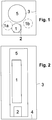
- FIG. 1 a mixing column 1 and a supercooling countercurrent 2 are arranged in a common coldbox 3.
- High-pressure column and low-pressure column of the distillation column system for nitrogen-oxygen separation are realized as a classic double column 5 and also housed in the common cold box 3.
- FIG. 2 shows the same arrangement in another view.
- FIG. 1 From the common coldbox 3 are in FIG. 1 only the lateral outer walls are shown. Details such as piping, valves and the interior of the apparatus 1, 2, 5 are not shown in the drawings.
- the space between the apparatus 1, 2, 5 and the outer wall of the common cold box 3 is filled with perlite.
- the underside of the common coldbox 3 is formed by a separate outer wall.
- the double column 5 is supported via a frame, not shown, on the bottom 4 of the common cold box 3.
- the mixing column 1 and the supercooling countercurrent are based on also not shown connecting elements on the double column 5 from. These fasteners are the same or similar to those in FIG. 3 executed connecting elements executed.
- a main heat exchanger is housed in the first embodiment in a separate further coldbox (in the Figures 1 and 2 not shown).
- the two dashed circles 1a and 1b in FIG. 1 represent two modifications of the first embodiment, in which the mixing column is arranged offset to the supercooling countercurrent 2. However, the mixing column is here also above the supercooling countercurrent arranged (analogous to FIG. 2 ).
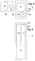
- the mixing column 1 and the double column 5 are arranged in the common coldbox 3.
- the subcooling countercurrent 2 is housed in another coldbox 12, together with the main heat exchanger 6.
- the main heat exchanger 6 is formed in the embodiment by a single heat exchanger block, in particular a plate heat exchanger. Alternatively, it may be formed by two or more blocks arranged horizontally next to each other and / or vertically one above the other.
- the supercooling countercurrent 2 may be arranged below the main heat exchanger 6.
- FIG. 4 shows the same common coldbox in different view.
- the space between the apparatus 1, 2, 5 and the outer wall of the common cold box 3 is filled with perlite.
- the underside of the common coldbox 3 is formed by a separate outer wall.
- the double column 5 is supported on the bottom 4 of the common cold box 3 via a frame (frame), not shown.
- the mixing column 1 is supported exclusively on the double column 5, specifically via at least two connecting elements which are respectively arranged in the upper and lower region of the mixing column 1.
- the connecting elements are dimensioned accordingly, if necessary, more than two connecting elements can be used.
- two pairs of connecting elements are used, which are each arranged in the upper and lower regions of the mixing column 1.
- the upper pair of these connecting elements 10, 11 is in FIG. 3 shown schematically.
- the upper element is preferably designed as a fixed point (welded or screwed on both columns), but the lower element is designed as a guide bearing in order to compensate for temperature stresses. This guide bearing fixes the horizontal arrangement and allows relative movement of mixing column and double column in the vertical direction.
- the roughly dashed line 14 in FIG. 3 represents a conceived rectangle, which has purely geometrical meaning, but to which no apparatus part corresponds.
- the space between the dashed line 14 and the outer wall 3 of the box here marks the minimum insulation distance in which no cold component may be located.
- the imaginary rectangle 14 is in the horizontal, is oriented parallel to the walls of the coldbox 3 and lies also on the outer walls of the two columns 1, 5 at.
- the mixing column 1 is preferably arranged in a corner of this rectangle 14, that is, it is touched by the rectangle 14 in two places. ( FIG. 4 For reasons of drawing, this aspect is not completely correct.)
- the fine dashed lines in the FIGS. 3 and 4 represent a modification of the first embodiment, in which the mixing column 1a is arranged differently.
- the upper end 24 of the mixing column is located 0.4 m below the upper end 15 of the double column 5 at a total height of the double column of about 35 m.
- the orientation of the two cold boxes to each other may be different from that shown in the drawings and depending on the spatial boundary conditions are arbitrary.
Landscapes
- Engineering & Computer Science (AREA)
- Physics & Mathematics (AREA)
- Mechanical Engineering (AREA)
- Thermal Sciences (AREA)
- General Engineering & Computer Science (AREA)
- Separation By Low-Temperature Treatments (AREA)
Claims (7)
- Dispositif destiné à la séparation cryogénique d'air, pourvu d'un échangeur thermique principal (6), doté d'un système de colonnes de distillation pour la séparation oxygène/azote (5), qui comporte une double colonne (5) contenant une colonne haute pression et une colonne basse pression, pourvu d'une colonne mélangeuse (1) et pourvu de moyens destinés à introduire de l'air de charge par l'intermédiaire de l'échangeur thermique principal (6) dans la colonne haute pression et dans la colonne mélangeuse, pourvu d'un conduit à oxygène liquide, destiné à introduire de l'oxygène liquide sortant de la colonne basse pression dans la zone supérieure de la colonne mélangeuse (1) et pourvu d'un conduit à produits d'oxygène, destiné au soutirage d'oxygène gazeux hors de la zone supérieure de la colonne mélangeuse (1) via l'échangeur thermique principal (6), la colonne mélangeuse (1) étant placée latéralement à côté de la double colonne (5), caractérisé en ce que la colonne mélangeuse (1) et la double colonne (5) sont placées dans une boîte froide (3) commune et en ce que la colonne mélangeuse (1) est fixée par l'intermédiaire d'éléments de liaison (10, 11) latéralement sur la double colonne (5), la colonne mélangeuse (1) étant supportée par l'intermédiaire des éléments de liaison (10, 11) sur la double colonne (5).
- Dispositif selon la revendication 1, caractérisé en ce que la colonne mélangeuse (1) n'est pas soutenue par le dessous.
- Dispositif selon la revendication 1 ou 2, caractérisé en ce que l'échangeur thermique principal (6) est placé dans une boîte froide (12) additionnelle, séparée de la boîte froide (3).
- Dispositif selon l'une quelconque de la revendication 3, caractérisé par un échangeur de sous-refroidissement à contre-courant (2), qui est placé dans une boîte froide (12) additionnelle.
- Dispositif selon l'une quelconque des revendications précédentes 1 à 3, caractérisé par un échangeur de sous-refroidissement à contre-courant (2), qui est placé dans la boîte froide (3) commune, en-dessous de la colonne mélangeuse (1).
- Dispositif selon l'une quelconque des revendications précédentes 1 à 5, caractérisé en ce que l'extrémité supérieure (24) de la colonne mélangeuse (1) est placée au moins à hauteur de l'extrémité supérieure (15) de la double colonne (5) ou en-dessous de la valeur d'au plus un cinquième de la longueur de la double colonne (5) de l'extrémité supérieure de la double colonne (5).
- Dispositif selon l'une quelconque des revendications précédentes 1 à 6, caractérisé en ce que la colonne mélangeuse (1) est placée dans un angle d'un rectangle (14) qui se situe dans l'horizontale, qui est orienté à la parallèle des parois de la boîte froide (3) commune et qui touche les parois extérieures de la de colonne mélangeuse (1) et de la double colonne (5).
Priority Applications (1)
| Application Number | Priority Date | Filing Date | Title |
|---|---|---|---|
| PL11714930T PL2553370T3 (pl) | 2010-03-26 | 2011-03-25 | Urządzenie do niskotemperaturowej separacji powietrza |
Applications Claiming Priority (3)
| Application Number | Priority Date | Filing Date | Title |
|---|---|---|---|
| DE102010012920A DE102010012920A1 (de) | 2010-03-26 | 2010-03-26 | Vorrichtung zur Tieftemperaturzerlegung von Luft |
| PCT/EP2011/001004 WO2011116871A2 (fr) | 2010-03-26 | 2011-03-01 | Dispositif pour le fractionnement cryogénique de l'air |
| PCT/EP2011/001509 WO2011116981A2 (fr) | 2010-03-26 | 2011-03-25 | Dispositif pour la décomposition à basse température d'air |
Publications (2)
| Publication Number | Publication Date |
|---|---|
| EP2553370A2 EP2553370A2 (fr) | 2013-02-06 |
| EP2553370B1 true EP2553370B1 (fr) | 2019-05-15 |
Family
ID=46245691
Family Applications (1)
| Application Number | Title | Priority Date | Filing Date |
|---|---|---|---|
| EP11714930.2A Active EP2553370B1 (fr) | 2010-03-26 | 2011-03-25 | Dispositif pour la séparation cryogénique d'air |
Country Status (3)
| Country | Link |
|---|---|
| EP (1) | EP2553370B1 (fr) |
| PL (1) | PL2553370T3 (fr) |
| WO (1) | WO2011116981A2 (fr) |
Families Citing this family (6)
| Publication number | Priority date | Publication date | Assignee | Title |
|---|---|---|---|---|
| JP5817327B2 (ja) * | 2010-09-29 | 2015-11-18 | 東ソー株式会社 | 酸化物焼結体、その製造方法、それを用いて得られる酸化物透明導電膜及び太陽電池 |
| DE102011015233A1 (de) | 2011-03-25 | 2012-09-27 | Linde Ag | Vorrichtung zur Tieftemperaturzerlegung von Luft |
| DE102012006484A1 (de) * | 2012-03-29 | 2013-10-02 | Linde Aktiengesellschaft | Transportables Paket mit einer Coldbox und Verfahren zum Herstellen einer Tieftemperatur-Luftzerlegungsanlage |
| US10145514B2 (en) * | 2013-11-18 | 2018-12-04 | Man Energy Solutions Se | Cold-box system and method for power management aboard ships |
| FR3119884B1 (fr) * | 2021-02-18 | 2022-12-30 | Air Liquide | Procédé de séparation d’air par distillation cryogénique |
| FR3123113B1 (fr) * | 2021-05-19 | 2023-06-09 | Air Liquide | Colonne de distillation et méthode de transportation d’une colonne de distillation |
Citations (1)
| Publication number | Priority date | Publication date | Assignee | Title |
|---|---|---|---|---|
| WO2011116871A2 (fr) * | 2010-03-26 | 2011-09-29 | Linde Aktiengesellschaft | Dispositif pour le fractionnement cryogénique de l'air |
Family Cites Families (19)
| Publication number | Priority date | Publication date | Assignee | Title |
|---|---|---|---|---|
| US4022030A (en) | 1971-02-01 | 1977-05-10 | L'air Liquide, Societe Anonyme Pour L'etude Et L'exploitation Des Procedes Georges Claude | Thermal cycle for the compression of a fluid by the expansion of another fluid |
| US5454227A (en) | 1994-08-17 | 1995-10-03 | The Boc Group, Inc. | Air separation method and apparatus |
| US5490391A (en) | 1994-08-25 | 1996-02-13 | The Boc Group, Inc. | Method and apparatus for producing oxygen |
| DE19803437A1 (de) | 1998-01-29 | 1999-03-18 | Linde Ag | Verfahren und Vorrichtung zur Gewinnung eines Druckprodukts durch Tieftemperaturzerlegung von Luft |
| FR2774752B1 (fr) | 1998-02-06 | 2000-06-16 | Air Liquide | Installation de distillation d'air et boite froide correspondante |
| FR2778234B1 (fr) | 1998-04-30 | 2000-06-02 | Air Liquide | Installation de distillation d'air et boite froide correspondante |
| FR2778233B1 (fr) | 1998-04-30 | 2000-06-02 | Air Liquide | Installation de distillation d'air et boite froide correspondante |
| US6134915A (en) * | 1999-03-30 | 2000-10-24 | The Boc Group, Inc. | Distillation column arrangement for air separation plant |
| DE19951521A1 (de) | 1999-10-26 | 2001-05-03 | Linde Ag | Verfahren und Vorrichtung zur Gewinnung eines Druckprodukts durch Tieftemperaturzerlegung von Luft |
| DE10015602A1 (de) | 2000-03-29 | 2001-10-04 | Linde Ag | Verfahren und Vorrichtung zur Gewinnung eines Druckprodukts durch Tieftemperaturzerlegung von Luft |
| DE10139727A1 (de) | 2001-08-13 | 2003-02-27 | Linde Ag | Verfahren und Vorrichtung zur Gewinnung eines Druckprodukts durch Tieftemperaturzerlegung von Luft |
| DE10161584A1 (de) * | 2001-12-14 | 2003-06-26 | Linde Ag | Vorrichtung und Verfahren zur Erzeugung gasförmigen Sauerstoffs unter erhöhtem Druck |
| DE10209421A1 (de) | 2002-03-05 | 2003-04-03 | Linde Ag | Verfahren und Vorrichtung zur Gewinnung eines Druckprodukts durch Tieftemperaturzerlegung von Luft |
| DE10217093A1 (de) | 2002-04-17 | 2003-01-23 | Linde Ag | Verfahren zur Regelung eines Trennsäulen-Systems zur Gaszerlegung |
| DE10228111A1 (de) | 2002-06-24 | 2004-01-15 | Linde Ag | Luftzerlegungsverfahren und -anlage mit Mischsäule und Krypton-Xenon-Gewinnung |
| EP1387136A1 (fr) | 2002-08-02 | 2004-02-04 | Linde AG | Procédé et appareil de production d'oxygène impur par distillation cryogénique de l'air |
| GB0307404D0 (en) * | 2003-03-31 | 2003-05-07 | Air Prod & Chem | Apparatus for cryogenic air distillation |
| EP1666824A1 (fr) | 2004-12-03 | 2006-06-07 | Linde Aktiengesellschaft | Procédé et dispositif pour la récupération d'Argon par séparation cryogénique d'air |
| US7621152B2 (en) * | 2006-02-24 | 2009-11-24 | Praxair Technology, Inc. | Compact cryogenic plant |
-
2011
- 2011-03-25 EP EP11714930.2A patent/EP2553370B1/fr active Active
- 2011-03-25 PL PL11714930T patent/PL2553370T3/pl unknown
- 2011-03-25 WO PCT/EP2011/001509 patent/WO2011116981A2/fr active Application Filing
Patent Citations (1)
| Publication number | Priority date | Publication date | Assignee | Title |
|---|---|---|---|---|
| WO2011116871A2 (fr) * | 2010-03-26 | 2011-09-29 | Linde Aktiengesellschaft | Dispositif pour le fractionnement cryogénique de l'air |
Also Published As
| Publication number | Publication date |
|---|---|
| WO2011116981A2 (fr) | 2011-09-29 |
| WO2011116981A3 (fr) | 2012-08-30 |
| EP2553370A2 (fr) | 2013-02-06 |
| PL2553370T3 (pl) | 2019-11-29 |
Similar Documents
| Publication | Publication Date | Title |
|---|---|---|
| EP2553370B1 (fr) | Dispositif pour la séparation cryogénique d'air | |
| DE19904526B4 (de) | Luftdestillationsanlage und zugehörige Kältebox | |
| EP2553369B1 (fr) | Dispositif pour le fractionnement cryogénique de l'air | |
| EP2503269B1 (fr) | Dispositif de décomposition à basse température de l'air | |
| WO2004005651A1 (fr) | Enveloppe en tole pour boite froide | |
| EP2841858A2 (fr) | Paquet transportable comprenant une boîte froide, installation de décomposition de l'air à basse température et procédé de fabrication d'une installation de décomposition de l'air à basse température | |
| EP2986924B1 (fr) | Dispositif pouvant être rééquipé, destiné à la décomposition à basse température de l'air, installation pouvant être rééquipée et procédé de rééquipement d'une installation de décomposition de l'air à basse température | |
| WO2020038608A1 (fr) | Système de séparation d'air, procédé de séparation d'air à basse température et procédé de construction d'une installation de séparation d'air | |
| DE10040391A1 (de) | Tieftemperaturluftzerlegungsanlage | |
| EP3592653B1 (fr) | Dispositif de transport et procédé et dispositif de fabrication du dispositif de transport | |
| WO2014154399A1 (fr) | Couloir de refroidissement pourvu d'une rampe de pulvérisation inférieure | |
| WO2016146246A1 (fr) | Système permettant de produire de l'oxygène par fractionnement d'air à basse température | |
| EP3067649A1 (fr) | Système de colonnes de distillation et procédé de production d'oxygène par séparation cryogénique de l'air | |
| EP1473531B1 (fr) | Système de colonne et procédé pour sa réalisation | |
| DE202009004099U1 (de) | Vorrichtung zur Tieftemperaturzerlegung von Luft | |
| EP3176526A1 (fr) | Procede et agencement de transfert de fluide | |
| EP2645032A1 (fr) | Paquet transportable avec boîtier frigorifique et procédé de fabrication d'une installation de décomposition de l'air à basse température | |
| EP2831524A2 (fr) | Pack transportable comportant une boîte cryogénique et procédé pour fabriquer une installation de fractionnement de l'air à basse température | |
| EP3067648A1 (fr) | Système de colonnes de distillation et procédé de production d'oxygène par séparation cryogénique de l'air | |
| DE102011116498A1 (de) | Doppelsäule für eine Tieftemperatur-Luftzerlegungsanlage | |
| DE10319755A1 (de) | Kolonnensystem und Verfahren zu dessen Herstellung | |
| WO2020038606A1 (fr) | Installation de séparation d'air, procédé pour séparer l'air à basse température au moyen de l'installation de séparation d'air et procédé pour réaliser une installation de séparation d'air | |
| WO2023030682A2 (fr) | Installation et procédé de séparation cryogénique de l'air | |
| EP4177004A1 (fr) | Dispositif et ensemble de soudage bout à bout de plaques métalliques, procédé d'alignement de plaques métalliques pour un processus de soudage ainsi que de fabrication d'un réservoir et utilisation d'un tel dispositif | |
| DE202018004476U1 (de) | Luftzerlegungsanlage und Luftzerlegungsanlagensystem |
Legal Events
| Date | Code | Title | Description |
|---|---|---|---|
| PUAI | Public reference made under article 153(3) epc to a published international application that has entered the european phase |
Free format text: ORIGINAL CODE: 0009012 |
|
| 17P | Request for examination filed |
Effective date: 20120809 |
|
| AK | Designated contracting states |
Kind code of ref document: A2 Designated state(s): AL AT BE BG CH CY CZ DE DK EE ES FI FR GB GR HR HU IE IS IT LI LT LU LV MC MK MT NL NO PL PT RO RS SE SI SK SM TR |
|
| DAX | Request for extension of the european patent (deleted) | ||
| 17Q | First examination report despatched |
Effective date: 20160307 |
|
| STAA | Information on the status of an ep patent application or granted ep patent |
Free format text: STATUS: EXAMINATION IS IN PROGRESS |
|
| GRAP | Despatch of communication of intention to grant a patent |
Free format text: ORIGINAL CODE: EPIDOSNIGR1 |
|
| STAA | Information on the status of an ep patent application or granted ep patent |
Free format text: STATUS: GRANT OF PATENT IS INTENDED |
|
| INTG | Intention to grant announced |
Effective date: 20190103 |
|
| GRAS | Grant fee paid |
Free format text: ORIGINAL CODE: EPIDOSNIGR3 |
|
| GRAA | (expected) grant |
Free format text: ORIGINAL CODE: 0009210 |
|
| STAA | Information on the status of an ep patent application or granted ep patent |
Free format text: STATUS: THE PATENT HAS BEEN GRANTED |
|
| AK | Designated contracting states |
Kind code of ref document: B1 Designated state(s): AL AT BE BG CH CY CZ DE DK EE ES FI FR GB GR HR HU IE IS IT LI LT LU LV MC MK MT NL NO PL PT RO RS SE SI SK SM TR |
|
| REG | Reference to a national code |
Ref country code: CH Ref legal event code: EP Ref country code: GB Ref legal event code: FG4D Free format text: NOT ENGLISH |
|
| REG | Reference to a national code |
Ref country code: IE Ref legal event code: FG4D Free format text: LANGUAGE OF EP DOCUMENT: GERMAN |
|
| REG | Reference to a national code |
Ref country code: DE Ref legal event code: R096 Ref document number: 502011015723 Country of ref document: DE |
|
| REG | Reference to a national code |
Ref country code: RO Ref legal event code: EPE |
|
| REG | Reference to a national code |
Ref country code: NL Ref legal event code: MP Effective date: 20190515 |
|
| REG | Reference to a national code |
Ref country code: LT Ref legal event code: MG4D |
|
| PG25 | Lapsed in a contracting state [announced via postgrant information from national office to epo] |
Ref country code: AL Free format text: LAPSE BECAUSE OF FAILURE TO SUBMIT A TRANSLATION OF THE DESCRIPTION OR TO PAY THE FEE WITHIN THE PRESCRIBED TIME-LIMIT Effective date: 20190515 Ref country code: PT Free format text: LAPSE BECAUSE OF FAILURE TO SUBMIT A TRANSLATION OF THE DESCRIPTION OR TO PAY THE FEE WITHIN THE PRESCRIBED TIME-LIMIT Effective date: 20190915 Ref country code: NL Free format text: LAPSE BECAUSE OF FAILURE TO SUBMIT A TRANSLATION OF THE DESCRIPTION OR TO PAY THE FEE WITHIN THE PRESCRIBED TIME-LIMIT Effective date: 20190515 Ref country code: LT Free format text: LAPSE BECAUSE OF FAILURE TO SUBMIT A TRANSLATION OF THE DESCRIPTION OR TO PAY THE FEE WITHIN THE PRESCRIBED TIME-LIMIT Effective date: 20190515 Ref country code: NO Free format text: LAPSE BECAUSE OF FAILURE TO SUBMIT A TRANSLATION OF THE DESCRIPTION OR TO PAY THE FEE WITHIN THE PRESCRIBED TIME-LIMIT Effective date: 20190815 Ref country code: HR Free format text: LAPSE BECAUSE OF FAILURE TO SUBMIT A TRANSLATION OF THE DESCRIPTION OR TO PAY THE FEE WITHIN THE PRESCRIBED TIME-LIMIT Effective date: 20190515 Ref country code: SE Free format text: LAPSE BECAUSE OF FAILURE TO SUBMIT A TRANSLATION OF THE DESCRIPTION OR TO PAY THE FEE WITHIN THE PRESCRIBED TIME-LIMIT Effective date: 20190515 Ref country code: FI Free format text: LAPSE BECAUSE OF FAILURE TO SUBMIT A TRANSLATION OF THE DESCRIPTION OR TO PAY THE FEE WITHIN THE PRESCRIBED TIME-LIMIT Effective date: 20190515 |
|
| PG25 | Lapsed in a contracting state [announced via postgrant information from national office to epo] |
Ref country code: RS Free format text: LAPSE BECAUSE OF FAILURE TO SUBMIT A TRANSLATION OF THE DESCRIPTION OR TO PAY THE FEE WITHIN THE PRESCRIBED TIME-LIMIT Effective date: 20190515 Ref country code: GR Free format text: LAPSE BECAUSE OF FAILURE TO SUBMIT A TRANSLATION OF THE DESCRIPTION OR TO PAY THE FEE WITHIN THE PRESCRIBED TIME-LIMIT Effective date: 20190816 Ref country code: LV Free format text: LAPSE BECAUSE OF FAILURE TO SUBMIT A TRANSLATION OF THE DESCRIPTION OR TO PAY THE FEE WITHIN THE PRESCRIBED TIME-LIMIT Effective date: 20190515 Ref country code: BG Free format text: LAPSE BECAUSE OF FAILURE TO SUBMIT A TRANSLATION OF THE DESCRIPTION OR TO PAY THE FEE WITHIN THE PRESCRIBED TIME-LIMIT Effective date: 20190815 |
|
| PG25 | Lapsed in a contracting state [announced via postgrant information from national office to epo] |
Ref country code: CZ Free format text: LAPSE BECAUSE OF FAILURE TO SUBMIT A TRANSLATION OF THE DESCRIPTION OR TO PAY THE FEE WITHIN THE PRESCRIBED TIME-LIMIT Effective date: 20190515 Ref country code: SK Free format text: LAPSE BECAUSE OF FAILURE TO SUBMIT A TRANSLATION OF THE DESCRIPTION OR TO PAY THE FEE WITHIN THE PRESCRIBED TIME-LIMIT Effective date: 20190515 Ref country code: DK Free format text: LAPSE BECAUSE OF FAILURE TO SUBMIT A TRANSLATION OF THE DESCRIPTION OR TO PAY THE FEE WITHIN THE PRESCRIBED TIME-LIMIT Effective date: 20190515 Ref country code: EE Free format text: LAPSE BECAUSE OF FAILURE TO SUBMIT A TRANSLATION OF THE DESCRIPTION OR TO PAY THE FEE WITHIN THE PRESCRIBED TIME-LIMIT Effective date: 20190515 |
|
| REG | Reference to a national code |
Ref country code: DE Ref legal event code: R097 Ref document number: 502011015723 Country of ref document: DE |
|
| PG25 | Lapsed in a contracting state [announced via postgrant information from national office to epo] |
Ref country code: SM Free format text: LAPSE BECAUSE OF FAILURE TO SUBMIT A TRANSLATION OF THE DESCRIPTION OR TO PAY THE FEE WITHIN THE PRESCRIBED TIME-LIMIT Effective date: 20190515 Ref country code: IT Free format text: LAPSE BECAUSE OF FAILURE TO SUBMIT A TRANSLATION OF THE DESCRIPTION OR TO PAY THE FEE WITHIN THE PRESCRIBED TIME-LIMIT Effective date: 20190515 |
|
| PLBE | No opposition filed within time limit |
Free format text: ORIGINAL CODE: 0009261 |
|
| STAA | Information on the status of an ep patent application or granted ep patent |
Free format text: STATUS: NO OPPOSITION FILED WITHIN TIME LIMIT |
|
| PG25 | Lapsed in a contracting state [announced via postgrant information from national office to epo] |
Ref country code: TR Free format text: LAPSE BECAUSE OF FAILURE TO SUBMIT A TRANSLATION OF THE DESCRIPTION OR TO PAY THE FEE WITHIN THE PRESCRIBED TIME-LIMIT Effective date: 20190515 |
|
| 26N | No opposition filed |
Effective date: 20200218 |
|
| PG25 | Lapsed in a contracting state [announced via postgrant information from national office to epo] |
Ref country code: SI Free format text: LAPSE BECAUSE OF FAILURE TO SUBMIT A TRANSLATION OF THE DESCRIPTION OR TO PAY THE FEE WITHIN THE PRESCRIBED TIME-LIMIT Effective date: 20190515 |
|
| REG | Reference to a national code |
Ref country code: DE Ref legal event code: R081 Ref document number: 502011015723 Country of ref document: DE Owner name: LINDE GMBH, DE Free format text: FORMER OWNER: LINDE AKTIENGESELLSCHAFT, 80331 MUENCHEN, DE |
|
| PG25 | Lapsed in a contracting state [announced via postgrant information from national office to epo] |
Ref country code: ES Free format text: LAPSE BECAUSE OF FAILURE TO SUBMIT A TRANSLATION OF THE DESCRIPTION OR TO PAY THE FEE WITHIN THE PRESCRIBED TIME-LIMIT Effective date: 20190515 Ref country code: MC Free format text: LAPSE BECAUSE OF FAILURE TO SUBMIT A TRANSLATION OF THE DESCRIPTION OR TO PAY THE FEE WITHIN THE PRESCRIBED TIME-LIMIT Effective date: 20190515 |
|
| REG | Reference to a national code |
Ref country code: CH Ref legal event code: PL |
|
| REG | Reference to a national code |
Ref country code: BE Ref legal event code: MM Effective date: 20200331 |
|
| PG25 | Lapsed in a contracting state [announced via postgrant information from national office to epo] |
Ref country code: LU Free format text: LAPSE BECAUSE OF NON-PAYMENT OF DUE FEES Effective date: 20200325 |
|
| PG25 | Lapsed in a contracting state [announced via postgrant information from national office to epo] |
Ref country code: IE Free format text: LAPSE BECAUSE OF NON-PAYMENT OF DUE FEES Effective date: 20200325 Ref country code: LI Free format text: LAPSE BECAUSE OF NON-PAYMENT OF DUE FEES Effective date: 20200331 Ref country code: CH Free format text: LAPSE BECAUSE OF NON-PAYMENT OF DUE FEES Effective date: 20200331 |
|
| PG25 | Lapsed in a contracting state [announced via postgrant information from national office to epo] |
Ref country code: BE Free format text: LAPSE BECAUSE OF NON-PAYMENT OF DUE FEES Effective date: 20200331 |
|
| GBPC | Gb: european patent ceased through non-payment of renewal fee |
Effective date: 20200325 |
|
| PG25 | Lapsed in a contracting state [announced via postgrant information from national office to epo] |
Ref country code: GB Free format text: LAPSE BECAUSE OF NON-PAYMENT OF DUE FEES Effective date: 20200325 |
|
| REG | Reference to a national code |
Ref country code: AT Ref legal event code: MM01 Ref document number: 1133932 Country of ref document: AT Kind code of ref document: T Effective date: 20200325 |
|
| PG25 | Lapsed in a contracting state [announced via postgrant information from national office to epo] |
Ref country code: AT Free format text: LAPSE BECAUSE OF NON-PAYMENT OF DUE FEES Effective date: 20200325 |
|
| PG25 | Lapsed in a contracting state [announced via postgrant information from national office to epo] |
Ref country code: MT Free format text: LAPSE BECAUSE OF FAILURE TO SUBMIT A TRANSLATION OF THE DESCRIPTION OR TO PAY THE FEE WITHIN THE PRESCRIBED TIME-LIMIT Effective date: 20190515 Ref country code: CY Free format text: LAPSE BECAUSE OF FAILURE TO SUBMIT A TRANSLATION OF THE DESCRIPTION OR TO PAY THE FEE WITHIN THE PRESCRIBED TIME-LIMIT Effective date: 20190515 |
|
| PG25 | Lapsed in a contracting state [announced via postgrant information from national office to epo] |
Ref country code: MK Free format text: LAPSE BECAUSE OF FAILURE TO SUBMIT A TRANSLATION OF THE DESCRIPTION OR TO PAY THE FEE WITHIN THE PRESCRIBED TIME-LIMIT Effective date: 20190515 Ref country code: IS Free format text: LAPSE BECAUSE OF FAILURE TO SUBMIT A TRANSLATION OF THE DESCRIPTION OR TO PAY THE FEE WITHIN THE PRESCRIBED TIME-LIMIT Effective date: 20190915 |
|
| PGFP | Annual fee paid to national office [announced via postgrant information from national office to epo] |
Ref country code: FR Payment date: 20230320 Year of fee payment: 13 |
|
| PGFP | Annual fee paid to national office [announced via postgrant information from national office to epo] |
Ref country code: PL Payment date: 20230310 Year of fee payment: 13 |
|
| P01 | Opt-out of the competence of the unified patent court (upc) registered |
Effective date: 20230523 |
|
| PGFP | Annual fee paid to national office [announced via postgrant information from national office to epo] |
Ref country code: RO Payment date: 20240319 Year of fee payment: 14 Ref country code: DE Payment date: 20240321 Year of fee payment: 14 |