EP2551601B1 - Haushaltsgerät mit einer Haushaltsgerätetür und einer Beleuchtungseinrichtung - Google Patents
Haushaltsgerät mit einer Haushaltsgerätetür und einer Beleuchtungseinrichtung Download PDFInfo
- Publication number
- EP2551601B1 EP2551601B1 EP12178205.6A EP12178205A EP2551601B1 EP 2551601 B1 EP2551601 B1 EP 2551601B1 EP 12178205 A EP12178205 A EP 12178205A EP 2551601 B1 EP2551601 B1 EP 2551601B1
- Authority
- EP
- European Patent Office
- Prior art keywords
- light
- domestic appliance
- door
- light guide
- light source
- Prior art date
- Legal status (The legal status is an assumption and is not a legal conclusion. Google has not performed a legal analysis and makes no representation as to the accuracy of the status listed.)
- Active
Links
Images


Classifications
-
- F—MECHANICAL ENGINEERING; LIGHTING; HEATING; WEAPONS; BLASTING
- F24—HEATING; RANGES; VENTILATING
- F24C—DOMESTIC STOVES OR RANGES ; DETAILS OF DOMESTIC STOVES OR RANGES, OF GENERAL APPLICATION
- F24C15/00—Details
- F24C15/008—Illumination for oven cavities
-
- F—MECHANICAL ENGINEERING; LIGHTING; HEATING; WEAPONS; BLASTING
- F24—HEATING; RANGES; VENTILATING
- F24C—DOMESTIC STOVES OR RANGES ; DETAILS OF DOMESTIC STOVES OR RANGES, OF GENERAL APPLICATION
- F24C15/00—Details
- F24C15/02—Doors specially adapted for stoves or ranges
- F24C15/04—Doors specially adapted for stoves or ranges with transparent panels
Definitions
- a household appliance having a receiving space that can be loaded by a charging opening, wherein the charging opening can be closed by a household appliance door and the household appliance door has at least one cold area, which is arranged laterally of the charging opening in a closed state of the household appliance door, and at least one lighting device with at least a light source for illuminating the receiving space, wherein the at least one semiconductor light source is within the cold region, the cold region of a hot region covering the feed opening in a closed state of the household appliance door by means of a Separation is separated and the separation at least one Licht micleitö réelle for passing through the light generated by the at least one light source and at least one light guide extends through a Licht twistleitö Maschinen.
- the at least one light source By arranging the at least one light source in the cold area, it can be maintained at a low thermal level even at high temperatures in the receiving space. In particular, the light source is not exposed to direct heat radiation. Consequently, a particularly long life of the lighting device can be achieved, even if an associated household appliance is pyrolyserash.
- the cold area can in particular be that cold area which is located on that side of the household appliance door on which it can be pivoted or has at least one door hinge. Such a cold area is comparatively large, so that a sufficient, non-compressed installation space is available for accommodating the at least one light source. It is an embodiment that the cold area is a lower cold area.
- a lower cold area may in particular be understood to mean a cold area which is arranged below the feed opening in the closed state of the household appliance door.
- a cold area is available in particular for downwardly opening doors such as oven doors.
- the cold area in particular in the case of a laterally opening or laterally pivotable household appliance door, may be a cold side area (eg for refrigerators or microwave ovens) or, in particular, in the case of a household appliance door which opens upwards or pivots on the top side (eg in the case of a built-in appliance).
- the at least one light source is arranged in a partial region of the lower cold region, which extends up to 100 mm from a lower door edge and / or up to 150 mm from lateral door profiles.
- a semiconductor light source is particularly durable, structurally compact and can generate a high luminous flux.
- the at least one semiconductor light source comprises at least one light-emitting diode. If several LEDs are present, they can be lit in the same color or in different colors. A color can be monochrome (eg red, green, blue etc.) or multichrome (eg white). Several light emitting diodes can produce a mixed light; eg a white mixed light.
- the at least one light-emitting diode may contain at least one wavelength-converting phosphor (conversion LED). The phosphor may alternatively or additionally be arranged remotely from the light-emitting diode ("remote phosphor").
- the at least one light-emitting diode can be in the form of at least one individually housed light-emitting diode or in the form of at least one LED chip. Several LED chips can be mounted on a common substrate ("submount").
- the at least one light emitting diode may be equipped with at least one own and / or common optics for beam guidance, for example at least one Fresnel lens, collimator, and so on.
- inorganic light-emitting diodes for example based on InGaN or AllnGaP, it is generally also possible to use organic LEDs (OLEDs, for example polymer OLEDs).
- the at least one semiconductor light source may, for example, comprise at least one diode laser.
- the household appliance door may have at least one electrical connection to the associated (remaining) household appliance for supplying power to the at least one light source.
- an associated driver may be present in the household appliance door, in particular in the cold area, or alternatively in the (remaining) domestic appliance.
- the household appliance door is zwangsbelrichbar. As a result, a temperature in the appliance door is further lowered, which is a
- the waste heat generating light sources can be cooled particularly effectively.
- the at least one light source is thermally conductively connected to at least one heat sink. This improves heat dissipation and cooling of the light source and thus their life.
- the heatsink can simultaneously represent a holder for the light emitting diode for a compact design and easy installation.
- the heat sink or holder can be attached to a reflector for cost-effective production, for a reduction of mounting tolerances and for ease of installation and in particular be pre-assembled on this.
- the quay area is separated from a hot area covering the charging opening in a closed state of the household appliance door by partition, and the partition has at least one light transmission opening for passing light generated by the at least one light source. This facilitates light guidance between the cold area and the warm area.
- the partition may be at least partially permeable to air to allow a cooling air flow between panes of the appliance door.
- the illumination device has at least one light guide, in which light at least one light source can be coupled in and which is arranged and arranged to radiate light coupled into it into the receiving space.
- a light guide can be made thermally particularly insensitive, for example, in an embodiment of glass or glass ceramic.
- the glass is preferably borosilicate glass.
- the light guide consists of a vitreous material (glass, glass ceramic or the like). Glassy material is highly temperature resistant and typically transparent. An optical property can be easily and precisely changed by adding fillers. So the light guide likes as a diffusely scattering Be configured light guide.
- vitreous material is relatively inexpensive, versatile moldable and its surface easily retreatable.
- the optical fiber may be made of plastic, which further simplifies manufacture.
- the plastic is preferably a highly temperature-resistant plastic.
- the plastic is preferably made of polycarbonate (PC), acrylonitrile-butadiene-styrene (ABS) and / or polymethyl methacrylate (PMMA).
- the light guide can be a light guide which can guide light within its material or body ("light guide body").
- the light guide is in particular a body which can guide the light by means of total internal reflection (TIR body).
- TIR body total internal reflection
- the light guide is in particular a solid body.
- the at least one light guide is arranged between an inner pane and an adjacent pane (for example a front pane or an intermediate pane). This allows a particularly high illumination efficiency.
- a good thermal shielding of the windshield is possible in the presence of at least one washer, since then the at least one washer can be configured thick without affecting the lighting.
- the at least one light guide is integrated in a pane of the household appliance door. So parts can be saved and also a space can be reduced. In addition, an increased illumination efficiency compared to an arranged behind this disc light guide is made possible by avoiding surface reflections.
- this disk can be an intermediate disk for good heat shielding of the windshield, since the intermediate disk (s) can then also be made sufficiently thick.
- at least one optical waveguide can also be arranged between two intermediate disks, the intermediate disks then being made thinner, if appropriate, in order not to increase their installation space.
- At least one light guide extends at least over a height of the feed opening. So the recording room can over its entire height be illuminated, us even if at least one rack level o.ä. is occupied.
- the light guide is preferably oriented vertically.
- At least one optical waveguide can be set up and arranged for illuminating a plurality of (in particular all) insertion levels of the receiving space, in particular a vertical optical waveguide.
- a light guide may be arranged in particular perpendicular or horizontal.
- a vertical arrangement allows illumination over the height of the receiving space, in particular over several insertion levels.
- a vertical light guide preferably runs parallel to a door profile of the household appliance door.
- at least one vertically arranged light guide can be arranged in particular in a region of a left edge (left-hand arranged light guide) and / or a right edge (right-hand arranged light guide) of a viewing window of the household appliance door.
- a light guide arranged on the left-hand side and a light guide arranged on the right-hand side can in particular be designed and / or arranged mirror-symmetrically with respect to a door central axis in order to support a uniform illumination of the receiving space.
- At least one light guide may be set up and arranged for illumination of only one insertion level in each case.
- the light guide can be arranged in particular horizontally to allow uniform illumination across the width of the receiving space.
- a horizontally arranged light guide can be arranged in particular in a region of an upper edge and / or a lower edge of a viewing window of the household appliance door.
- At least one light guide thermally shields an adjacent door profile at least in regions.
- the light guide can therefore in particular be arranged between the receiving space and the door profile. As a result, heating of the door profile can be reduced, which is advantageous in particular for door profiles made of plastic.
- a light guide may in particular be a vertical light guide, which may extend in particular over the height of the feed opening.
- a thickness of at least one light guide is preferably between 5 mm and 30 mm.
- the thickness is not limited to this.
- a cross-sectional profile of at least one light guide is curved at least in sections and in particular circular-cylindrical, circular segment-shaped or oval may be formed.
- a curved or a more curved region of a lateral surface of the light guide preferably faces the receiving space.
- the cross-sectional profile is not limited thereto, but may be e.g. also angular and / or free-form.
- the light guide is preferably rectilinear, but may in principle also be curved.
- the optical waveguide has at least one surface area at which a light exit is prevented or suppressed, and has at least one (in particular complementary) surface area which is provided for a light emission, wherein the at least one surface area provided for a light emission is directed essentially into the receiving space.
- the at least one surface area preventing or suppressing light emission is masked, in particular opaque coated or roughened.
- a light guide where light leakage is to be prevented, light-absorbing or, preferably, for a high light output, be reflective coated.
- a roughening or other microstructuring can be effected for example by sandblasting or etching and makes the roughened surface area appear milky or diffuse. The roughening or other microstructuring causes a diffuse reflection or back reflection of the light into the light guide, often at an angle which causes an increased light emission from the light guide at the illuminated by the back reflection location of the light guide.
- the light guide is configured or prepared in a constant over its length circumferential angle ⁇ about its longitudinal axis L for a targeted light emission.
- the invention is not limited thereto, and the circumferential angle ⁇ may vary with the length of the optical fiber.
- the circumferential angle ⁇ is preferably in a range between about 45 ° and about 270 °, so that in a development intensified light in the complementary circumferential angle range between about 315 ° and about 90 ° can emerge (on which the surface of the Light guide is especially smooth and uncoated).
- the light guide may also have spaced over its length areas which have, for example, a mutually equal circumferential angle ⁇ .
- the regions can be arranged angularly offset in a row or, for example, also about the longitudinal axis.
- At least one optical fiber extends through a light transmission opening.
- the light guide upstream elements can be accommodated in the cold area, where they are thermally protected.
- the light guide is preceded by an intermediate piece, in which light at least one light source can be coupled and which forwards the coupled-in light to the light guide.
- the intermediate piece allows an effective coupling of light from the at least one light source and consequently a high luminous efficacy.
- the intermediate piece is preferably housed in the cold area.
- the intermediate piece is or has an optical element.
- a particularly versatile beam guidance can be achieved, in particular for a high luminous efficacy.
- the intermediate piece is made of plastic and the optical fiber is made of glass.
- the intermediate piece is preferably housed in the cold area, in particular in pyrolysis household appliances.
- the intermediate piece and the optical fiber may alternatively be used e.g. both are made of the same material, e.g. made of glass or plastic, in particular integrally formed. This simplifies a production.
- the light guide, the intermediate piece and the at least one associated light-emitting diode are arranged in series or collinear with each other, which allows a high photometric illumination efficiency.
- At least one light guide is associated with a reflector to reflect incident light from this light guide in the receiving space. This increases a luminous efficacy.
- the reflector may, for example, be specular or diffusely reflective.
- the reflector may further be configured tubular with a hollow cylindrical profile, which has at least one light exit opening in its lateral surface. The reflector can then absorb the light guide in particular.
- the hollow cylindrical profile may be circular cylindrical and / or angular.
- the at least one light exit opening may comprise a light exit opening extending over the entire length of the lateral surface.
- the at least one light exit opening can be directed in particular into the receiving space.
- the reflector can in particular serve as a heat shield, in particular to thermally shield a door profile against the receiving space.
- the reflector can also serve as a holder for at least one or another element of the lighting device.
- the household appliance can fall in particular in the field of "white goods” and in particular serve to do household chores such as cooking, baking, washing, cleaning and so on.
- the household appliance may be a large household appliance (eg comprising a refrigerator, a freezer, a freezer, an electric oven, a washing machine, a dishwasher and a tumble dryer) or a household appliance (eg comprising a microwave oven).
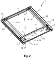
- the frame 3 delimits in a view from the front or rear at least about an area ("warm area” W) of the oven door 1, which a feed opening 11 of a closable from the oven door 1 receiving space or oven chamber 12 of a baking oven 13 (see more precisely Figure 6 ) directly covers.
- the intermediate discs 6, 7 are limited to heat insulation on this warm area W.
- the cold area K is zwangsbellusterbar by means of a blower (o.Fig.), So that it is flowed through by the flow of cooling air when the blower is switched on.
- the forced ventilation can be performed by means of a fan located in the oven door 1 (o.Fig.) Or arranged in a body of the oven 13 fan.
- the cold area K is separated from the heat area W by means of a partition 14, which is formed on a lower edge of the frame 3 and extends over the entire width between the door profiles 2.
- the outer sides of the door handle 10 and the door profiles 2 form on each side of an elongated guide 15 for sliding or rolling receiving a guide member (o.Fig.) To push the oven door 1 in a body of the oven 13 can.
- Fig.2 shows in an oblique view a back of the oven door 1 with the rear disc removed in a higher accuracy.
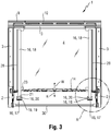
- Figure 3 shows the oven door 1 with removed rear inner pane 8 in a rear view.
- the oven door 1 also has a lighting device 16, by means of which the oven chamber 12 of the oven 13 can be illuminated (see more precisely Figure 6 ).
- the illumination device 16 has on the left side and on the right side in each case a light source Shape of a light emitting diode 17, to each of which a rod-shaped light guide 18 connects.
- the left-side part and the right-side part can in particular be designed to have the same effect in terms of shape analogously (eg mirror-symmetrically to a center line of the door).
- the LEDs 17 are located in the cold area K, so that they are sufficiently thermally protected even at high temperatures in the furnace chamber 12. For the light-emitting diodes 17 are firstly not directly exposed to the heat radiation emerging from the oven chamber 12 and also ventilated by the forced ventilation of the cold room K. As a result, the LEDs 17 can withstand temperatures of 400 ° C to 500 ° C in the furnace chamber 12 in a pyrolysis operation without a significant reduction in their life.
- the light emitting diodes 17 are each arranged on the left side or right side in a partial region of the lower cold region K, which extends up to 100 mm from a lower door edge 30 and up to 150 mm from a next door profile 2.
- the light-emitting diodes 17 are mounted on respective carriers 19, which in turn are glued to the windshield 4.
- the carriers 19 can also serve as heat sinks and for this purpose are preferably made of a good heat-conductive material, in particular with a thermal conductivity of more than 15 W / (m ⁇ K), for example aluminum.
- the serving as a heat sink support 19 can be flowed around by the cooling air flow flowing in the cold region K.
- the supports 19 may have on their outside at least one cooling structure (o.Fig.), E.g. Cooling fins, cooling pins, cooling fins, etc.
- the cooling structure may be integrally connected to the support 19, or e.g. as a dedicated heat sink to be fixedly connected to the carrier 19, e.g. be screwed or clamped or glued to it.
- heat dissipation from the light-emitting diodes 17 may be achieved by a thermally highly conductive connection to the door profiles 2, for example by means of a connection of the supports 19 with a respective door profile 2.
- the light-emitting diodes 17 may for example be clamped to the carrier 19 and / or be attached to the carrier via a thermal interface material (TIM).
- TIM thermal interface material
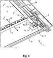
- the light emitting diodes 17 is arranged downstream of each one intermediate piece 20 and thus optically downstream.
- the intermediate piece 20 serves to couple light emitted by the associated light-emitting diode 17 and to decouple it in a targeted manner.
- the intermediate piece 20 for this purpose has a frustoconical basic shape and has a dome-like, for example, on a smaller lower cover surface facing the light-emitting diode 17. spherical cap-shaped recess (o.Fig.), Which overhangs the light emitting diode 17 at least substantially, and also laterally.
- the intermediate piece 20 thus also serves as an optical system or an optical element, here: for beam shaping.
- the intermediate piece 20 Since the intermediate piece 20 is completely in the cold region K, it does not need to meet any special thermal requirements and may consist of a thermally less resistant material, e.g. made of transparent plastic. However, the intermediate piece 20 is not limited thereto and may be e.g. made of glass, glass ceramic, etc. The intermediate piece 20 is also supported on the carrier 19.
- the light guide 18 Facing away from the recess, upper flat top surface 21 of the intermediate piece 20, the light guide 18 connects flat. Both the intermediate piece 20 and the light guide 18 conduct light by total internal reflection (TIR), so are designed as a TIR body. Light entering at the spherical cap-shaped recess is irradiated into the light guide 18 through the upper cover surface 21 if the refractive indices of the light guide 18 and the intermediate piece 20 are sufficiently coincident, especially with a same material (e.g., glass). To improve a light transmission, at least one optical transition layer (o.Fig.) May be provided on the upper cover surface 21.
- TIR total internal reflection
- the light guides 18 are each arranged vertically in the oven door 1 and parallel to the door profiles 2. They extend from the intermediate piece 20 to an upper crosspiece 22 of the frame 3.
- the optical waveguide 18, the intermediate piece 20 and the light-emitting diode 17 of a respective side are arranged in series or collinear with one another, which allows a high photometric illumination efficiency.
- a length of the respective light guide 18 is less here than a height of the oven door 1.
- the length of the light guide 18 is the same here.
- the separation For the passage of the optical waveguide 18 through the partition 14, the separation has two Licht twistleitö réelleen 23, through which a respective optical fiber 18 extends so that light 17 produced by the light-emitting diodes in the optical fibers 18 can be passed through the partition 14.
- the light guide 18 be made of a thermally resistant material, which in particular in the receiving space of e.g. 400 ° C to 500 ° C without damage.
- This material is preferably glass or glass ceramic.
- the light guide 18 and the intermediate piece 20 may be, e.g. for ease of assembly, be formed integrally, e.g. of glass.
- a light guide 18 then has, in particular, a section which corresponds to the intermediate piece 20 in shape and / or function, but is integrated in the light guide 18.
- the intermediate piece may be made of plastic (e.g., polycarbonate, PMMA or epoxy resin) and the glass optical fiber 18 or the like.
- the light guide 18 may be made of plastic.
- the light guides 18 are arranged and arranged to radiate light coupled thereinto through the charging opening 11 into the furnace chamber 12.
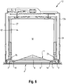
- Figure 6 shows in plan view a possible, of the two light guides 18 in the furnace chamber 12 irradiated light Lichtabstrahlmusters M.
- the Lichtabstrahlmuster M can illuminate a respective insertion level almost completely, highly uniformly.
- the light guides 18 have the further advantage that they can serve as a thermal barrier and so the adjacent door profile 2 against heat from the furnace chamber 12th can shield. This can be advantageous in particular for door profiles 2 made of plastic.
- the baking oven 13 has a muffle 27 which is open on one side by the feed opening 11 to form the oven space 12.
- the muffle 27 is separated from a housing 13 a of the oven 13 by a heat insulation 24.
- the oven door 1 is in its closed state shown laterally on a surrounding the feed opening surrounding flange 25 of the muffle 27.
- the two light guides 18 are arranged so that they lie at least in sections in the warm area W of the oven door 1, which allows a broad-angle light irradiation into the oven chamber 12.
- the light guides 18 are here seconded between the inner pane 8 and the intermediate pane 7 adjacent thereto, e.g. because then the intermediate discs 6, 7 can be configured thick without affecting the lighting.
- a thickness of the here circular cylindrical light guide 18 is preferably 5 mm to 30 mm, but is not limited thereto.
- a cross-sectional profile of the light guides 18 is here curved at least in sections and may be e.g. be circular cylindrical, circular segment or oval.
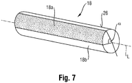
- a curved or a more strongly curved region of a lateral surface 26 of the light guide 18 preferably faces the furnace chamber 12.
- the light guides 18, in particular directly into the furnace chamber 12 these can be at least partially designed or prepared accordingly, in particular on its surface.
- a light guide 18 may be masked where light leakage is to be prevented.
- the optical waveguide 18 may be light-absorbing or, for a high luminous efficacy, it may be reflective coated.
- a light guide 18 in a region 18 a where a light leakage is to be prevented or suppressed, roughened or otherwise microstructured as appropriate.
- This microstructuring in particular Roughening, causes a diffuse reflection of the light into the light guide 18, and often at an angle which causes increased light emission from the light guide 18 at the illuminated by the back reflection location of the light guide 18.
- light is increasingly emitted from a non-roughened (smooth) portion 18b of the light guide 18.
- a roughening can be effected by sandblasting or etching and makes the roughened surface area appear milky or diffuse.
- an upper, free top surface of the light guides is also configured rather opaque.
- the optical waveguide 18 is preferably designed or prepared for a uniform light emission over its length in a circumferential angular range ⁇ that is constant over its length about its longitudinal axis L for a targeted emission of light.
- the circumferential angle range ⁇ is preferably between 45 ° and 270 °, so that in a development intensified light can emerge in the complementary circumferential angle range between 315 ° and 90 ° (on which the surface of the light guide 18 is in particular smooth and uncoated).
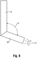
- Figure 8 shows a light guide 18, on which an intermediate piece at an angle ⁇ bent adjacent.
- the lighting device 16 may extend substantially over the entire height of the oven door 1.
- the bending angle ⁇ is here between 90 ° and 180 °.
- the light guide may be angled at the bending angle ⁇ .
- a reflector may be present on the light guides 18, which partially surrounds the light guide 18, in particular via its longitudinal section radiating into the furnace chamber 12 (in this case, the section protruding into the heat region W).
- Figure 9 a tubular or tubular reflector 28 with a circular sector-shaped configuration.
- the reflector 28 partially surrounds the light guide 18 (serving as a light emitting element) with respect to a circumferential direction.
- the reflector 28 surrounds the light guide 18 in a longitudinal section outside the cold room K or within the hot room W.
- the light passage opening 29 points in the direction of the furnace chamber 12. The orientation and size of the opening 29 allow the furnace chamber 12 to be specifically illuminated.
- the amplified light-emitting region 18b of the light guide 18 is directed in an analogous manner to the light exit opening 29. Thus, a high proportion of the light emitted by the light guide 18 is emitted directly from the light exit opening 29.
- the reflector 28 and the light guide are aligned parallel to each other in the longitudinal direction. Light radiated from the light guide 18 onto the reflector 28 can be reflected by the reflector 28 through the light passage opening 29 into the furnace chamber 12. Consequently, light emerging from the light guide 18 can be radiated directly into the furnace chamber 12 through the light passage opening 29 or indirectly via the reflector 28.
- the reflector 28 can also serve as a heat shield, which thermally shields the door profile 2 against the furnace chamber. This can be advantageous in particular for door profiles 2 made of plastic.
- the reflector 28 may be specular on its side facing the optical waveguide 18 or may be designed to be diffusely reflecting, for a uniform light emission.
- the reflector 28 may serve as a support for the light guide 18 at the same time.
- the reflector 28 may be in one or more parts. In a multi-part construction, different parts for different functions, e.g. be provided for reflecting, carrying, positioning, etc., which supports a standardization of components.
- the reflector 28 may be, for example, a reflective coated plastic body.
- the reflector 28, for example, a reflective coated or a shiny polished metal body be.
- a reflective coating may comprise, for example, aluminum and / or chromium.
- the reflector 28 may be an iron or steel sheet coated with high-gloss aluminum.
- the optical fibers may also be curved or angled in their length, that is, not just straight.
- the reflector can serve as a carrier for the light guide, the intermediate piece and the light-emitting diode (s).
- a prefabricated lighting unit can be manufactured and mounted in a particularly simple and possibly also standardized manner. Also, manufacturing tolerances can be reduced.
- only one light guide or may be more than two light guides may be provided.
Landscapes
- Engineering & Computer Science (AREA)
- Chemical & Material Sciences (AREA)
- Combustion & Propulsion (AREA)
- Mechanical Engineering (AREA)
- General Engineering & Computer Science (AREA)
- Arrangement Of Elements, Cooling, Sealing, Or The Like Of Lighting Devices (AREA)
- Planar Illumination Modules (AREA)
Priority Applications (1)
| Application Number | Priority Date | Filing Date | Title |
|---|---|---|---|
| PL12178205T PL2551601T3 (pl) | 2011-07-29 | 2012-07-27 | Urządzenie gospodarstwa domowego z drzwiami urządzenia gospodarstwa domowego oraz urządzeniem oświetleniowym |
Applications Claiming Priority (1)
| Application Number | Priority Date | Filing Date | Title |
|---|---|---|---|
| DE102011080078A DE102011080078A1 (de) | 2011-07-29 | 2011-07-29 | Haushaltsgerätetür mit Beleuchtungseinrichtung |
Publications (3)
| Publication Number | Publication Date |
|---|---|
| EP2551601A2 EP2551601A2 (de) | 2013-01-30 |
| EP2551601A3 EP2551601A3 (de) | 2013-04-03 |
| EP2551601B1 true EP2551601B1 (de) | 2017-03-15 |
Family
ID=46639338
Family Applications (1)
| Application Number | Title | Priority Date | Filing Date |
|---|---|---|---|
| EP12178205.6A Active EP2551601B1 (de) | 2011-07-29 | 2012-07-27 | Haushaltsgerät mit einer Haushaltsgerätetür und einer Beleuchtungseinrichtung |
Country Status (4)
| Country | Link |
|---|---|
| EP (1) | EP2551601B1 (pl) |
| DE (1) | DE102011080078A1 (pl) |
| ES (1) | ES2623919T3 (pl) |
| PL (1) | PL2551601T3 (pl) |
Families Citing this family (11)
| Publication number | Priority date | Publication date | Assignee | Title |
|---|---|---|---|---|
| DE102011088083A1 (de) * | 2011-12-09 | 2013-06-13 | BSH Bosch und Siemens Hausgeräte GmbH | Tür für ein Haushaltsgerät, Haushaltsgerät mit einer Tür und Verfahren zum Montieren eines Türprofils |
| DE102013205824A1 (de) * | 2013-04-03 | 2014-10-09 | BSH Bosch und Siemens Hausgeräte GmbH | Beleuchtungsvorrichtung für einen Innenraum eines Haushaltsgeräts sowie Haushaltsgerät mit einer derartigen Beleuchtungsvorrichtung |
| DE102013210823B3 (de) | 2013-06-10 | 2014-12-11 | Irlbacher Blickpunkt Glas Gmbh | LED-Heißraumleuchte sowie diese Heißraumleuchte enthaltendes Haushaltsgerät |
| ITPR20130017U1 (it) * | 2013-10-03 | 2015-04-04 | Bake Off Italiana S R L | Porta per forno di cottura ad uso alimentare e forno di cottura per alimenti |
| EP2977682B1 (en) | 2014-07-25 | 2018-05-30 | Electrolux Appliances Aktiebolag | Oven door, oven comprising an oven door and method for displaying information at an oven door |
| ES2564877B1 (es) * | 2014-09-25 | 2017-01-18 | BSH Electrodomésticos España S.A. | Aparato doméstico para el tratamiento de prendas de ropa con una ventana de cristal con revestimiento específico de una puerta |
| DE102015206579B4 (de) * | 2015-04-13 | 2024-10-17 | BSH Hausgeräte GmbH | Beleuchtungsvorrichtung zum Ausleuchten eines Garraums eines Gargeräts sowie Gargerät mit einer Beleuchtungsvorrichtung |
| DE202015103887U1 (de) | 2015-07-24 | 2015-08-28 | Debag Deutsche Backofenbau Gmbh | Tür für ein Gerät zur Wärmebehandlung von Lebensmitteln |
| KR102493915B1 (ko) * | 2016-06-03 | 2023-02-01 | 삼성전자주식회사 | 오븐 |
| DE102016013323A1 (de) * | 2016-11-09 | 2018-05-09 | Liebherr-Hausgeräte Ochsenhausen GmbH | Kühl- und/oder Gefriergerät |
| DE102022116376A1 (de) | 2022-06-30 | 2024-01-04 | Miele & Cie. Kg | Haushaltgerät, Verfahren zum Beleuchten einer Dufteinheit und Vorrichtung |
Family Cites Families (6)
| Publication number | Priority date | Publication date | Assignee | Title |
|---|---|---|---|---|
| DE3827528A1 (de) * | 1988-01-15 | 1989-08-10 | Cirbus Rudolf | Vorrichtung fuer die beleuchtung der backmuffel und des garraums |
| DE102005045367A1 (de) * | 2005-09-22 | 2007-03-29 | BSH Bosch und Siemens Hausgeräte GmbH | Innenraumbeleuchtungsvorrichtung |
| DE102007015237A1 (de) * | 2007-03-29 | 2008-10-02 | BSH Bosch und Siemens Hausgeräte GmbH | Hausgerätevorrichtung |
| EP1995522B1 (en) | 2007-05-25 | 2011-01-05 | Candy S.p.A. | Oven |
| US7874690B2 (en) * | 2008-06-24 | 2011-01-25 | Tyco Electronics Corporation | LED lighting fixture for illuminating a cavity |
| ITTO20090999A1 (it) * | 2009-12-17 | 2011-06-18 | Indesit Co Spa | Sistema di illuminazione per un forno domestico e ad un forno provvisto di tale sistema di illuminazione |
-
2011
- 2011-07-29 DE DE102011080078A patent/DE102011080078A1/de not_active Withdrawn
-
2012
- 2012-07-27 EP EP12178205.6A patent/EP2551601B1/de active Active
- 2012-07-27 ES ES12178205.6T patent/ES2623919T3/es active Active
- 2012-07-27 PL PL12178205T patent/PL2551601T3/pl unknown
Non-Patent Citations (1)
| Title |
|---|
| None * |
Also Published As
| Publication number | Publication date |
|---|---|
| DE102011080078A1 (de) | 2013-01-31 |
| PL2551601T3 (pl) | 2017-08-31 |
| EP2551601A3 (de) | 2013-04-03 |
| ES2623919T3 (es) | 2017-07-12 |
| EP2551601A2 (de) | 2013-01-30 |
Similar Documents
| Publication | Publication Date | Title |
|---|---|---|
| EP2551601B1 (de) | Haushaltsgerät mit einer Haushaltsgerätetür und einer Beleuchtungseinrichtung | |
| EP2602553B1 (de) | Haushaltsgerätetür mit Beleuchtungseinrichtung | |
| DE102011080073B4 (de) | Haushaltsgerätetür mit Beleuchtungseinrichtung | |
| EP2251588B1 (de) | Lampe für hausgerät sowie hausgerät, insbesondere zum zubereiten von lebensmitteln, mit einer lampe | |
| EP2049835B1 (de) | Leuchte | |
| EP2278228B1 (de) | Backofen mit einer Beleuchtungseinrichtung für den Behandlungsraum des Backofens | |
| DE102013206869A1 (de) | Geschirrspülmaschine mit wenigstens einem von einem Leuchtflächenelement und diesem beigeordneten Flächenelement überdeckten Durchbruch in mindestens einer Wand ihres Spülbehälters | |
| EP2815193A1 (de) | Kältegerät mit indirekter kühlkammerbeleuchtung | |
| DE102010060218A1 (de) | Beleuchtungsanordnung zur Beleuchtung einer Arbeitsplatte | |
| DE102011080072B4 (de) | Haushaltsgerätetür mit Beleuchtungseinrichtung | |
| DE102013206865A1 (de) | Geschirrspülmaschine mit zwei Leuchtflächenelementen in wenigstens einer Wand ihres Spülbehälters | |
| EP2236912A2 (de) | Leuchte | |
| EP2813765B1 (de) | LED-Heißraumleuchte sowie diese Heißraumleuchte enthaltendes Haushaltsgerät | |
| DE102020112524A1 (de) | Leuchte für ein elektrisches Haushaltsgerät, insbesondere einen Haushalts-Ofen | |
| WO2004097303A1 (de) | Gargerät | |
| DE102011080071B4 (de) | Haushaltsgerätetür mit Beleuchtungseinrichtung | |
| EP1598682A2 (de) | Faseroptische Vorrichtung zur Innenbeleuchtung von Küchen und Hausgeräten | |
| EP3290810B1 (de) | Haushaltegeräteleuchte | |
| WO2008135428A2 (de) | Beleuchtung für kältegerät mit transparenter tür | |
| DE102016116446B4 (de) | Haushaltsgeräteleuchte | |
| DE202009017408U1 (de) | LED-Kühlregalleuchte | |
| DE202012101368U1 (de) | Leuchte | |
| WO2011124399A1 (de) | Led-lampe | |
| DE102015208195A1 (de) | Kochfeld mit mindestens einer Halbleiterlichtquelle und Lichtstreukörper | |
| DE102017208003A1 (de) | Beleuchtungsvorrichtung für Haushaltsgerät und Haushaltsgerät |
Legal Events
| Date | Code | Title | Description |
|---|---|---|---|
| PUAI | Public reference made under article 153(3) epc to a published international application that has entered the european phase |
Free format text: ORIGINAL CODE: 0009012 |
|
| AK | Designated contracting states |
Kind code of ref document: A2 Designated state(s): AL AT BE BG CH CY CZ DE DK EE ES FI FR GB GR HR HU IE IS IT LI LT LU LV MC MK MT NL NO PL PT RO RS SE SI SK SM TR |
|
| AX | Request for extension of the european patent |
Extension state: BA ME |
|
| PUAL | Search report despatched |
Free format text: ORIGINAL CODE: 0009013 |
|
| AK | Designated contracting states |
Kind code of ref document: A3 Designated state(s): AL AT BE BG CH CY CZ DE DK EE ES FI FR GB GR HR HU IE IS IT LI LT LU LV MC MK MT NL NO PL PT RO RS SE SI SK SM TR |
|
| AX | Request for extension of the european patent |
Extension state: BA ME |
|
| RIC1 | Information provided on ipc code assigned before grant |
Ipc: F24C 15/00 20060101AFI20130227BHEP Ipc: F24C 15/04 20060101ALI20130227BHEP |
|
| 17P | Request for examination filed |
Effective date: 20131004 |
|
| RBV | Designated contracting states (corrected) |
Designated state(s): AL AT BE BG CH CY CZ DE DK EE ES FI FR GB GR HR HU IE IS IT LI LT LU LV MC MK MT NL NO PL PT RO RS SE SI SK SM TR |
|
| RAP1 | Party data changed (applicant data changed or rights of an application transferred) |
Owner name: BSH HAUSGERAETE GMBH |
|
| 17Q | First examination report despatched |
Effective date: 20160113 |
|
| GRAP | Despatch of communication of intention to grant a patent |
Free format text: ORIGINAL CODE: EPIDOSNIGR1 |
|
| INTG | Intention to grant announced |
Effective date: 20161020 |
|
| GRAS | Grant fee paid |
Free format text: ORIGINAL CODE: EPIDOSNIGR3 |
|
| GRAA | (expected) grant |
Free format text: ORIGINAL CODE: 0009210 |
|
| AK | Designated contracting states |
Kind code of ref document: B1 Designated state(s): AL AT BE BG CH CY CZ DE DK EE ES FI FR GB GR HR HU IE IS IT LI LT LU LV MC MK MT NL NO PL PT RO RS SE SI SK SM TR |
|
| REG | Reference to a national code |
Ref country code: CH Ref legal event code: EP Ref country code: GB Ref legal event code: FG4D Free format text: NOT ENGLISH |
|
| REG | Reference to a national code |
Ref country code: IE Ref legal event code: FG4D Free format text: LANGUAGE OF EP DOCUMENT: GERMAN |
|
| REG | Reference to a national code |
Ref country code: AT Ref legal event code: REF Ref document number: 875980 Country of ref document: AT Kind code of ref document: T Effective date: 20170415 |
|
| REG | Reference to a national code |
Ref country code: DE Ref legal event code: R096 Ref document number: 502012009768 Country of ref document: DE |
|
| REG | Reference to a national code |
Ref country code: ES Ref legal event code: FG2A Ref document number: 2623919 Country of ref document: ES Kind code of ref document: T3 Effective date: 20170712 |
|
| REG | Reference to a national code |
Ref country code: NL Ref legal event code: MP Effective date: 20170315 |
|
| REG | Reference to a national code |
Ref country code: LT Ref legal event code: MG4D |
|
| PG25 | Lapsed in a contracting state [announced via postgrant information from national office to epo] |
Ref country code: GR Free format text: LAPSE BECAUSE OF FAILURE TO SUBMIT A TRANSLATION OF THE DESCRIPTION OR TO PAY THE FEE WITHIN THE PRESCRIBED TIME-LIMIT Effective date: 20170616 Ref country code: LT Free format text: LAPSE BECAUSE OF FAILURE TO SUBMIT A TRANSLATION OF THE DESCRIPTION OR TO PAY THE FEE WITHIN THE PRESCRIBED TIME-LIMIT Effective date: 20170315 Ref country code: FI Free format text: LAPSE BECAUSE OF FAILURE TO SUBMIT A TRANSLATION OF THE DESCRIPTION OR TO PAY THE FEE WITHIN THE PRESCRIBED TIME-LIMIT Effective date: 20170315 Ref country code: NO Free format text: LAPSE BECAUSE OF FAILURE TO SUBMIT A TRANSLATION OF THE DESCRIPTION OR TO PAY THE FEE WITHIN THE PRESCRIBED TIME-LIMIT Effective date: 20170615 Ref country code: HR Free format text: LAPSE BECAUSE OF FAILURE TO SUBMIT A TRANSLATION OF THE DESCRIPTION OR TO PAY THE FEE WITHIN THE PRESCRIBED TIME-LIMIT Effective date: 20170315 |
|
| PG25 | Lapsed in a contracting state [announced via postgrant information from national office to epo] |
Ref country code: BG Free format text: LAPSE BECAUSE OF FAILURE TO SUBMIT A TRANSLATION OF THE DESCRIPTION OR TO PAY THE FEE WITHIN THE PRESCRIBED TIME-LIMIT Effective date: 20170615 Ref country code: RS Free format text: LAPSE BECAUSE OF FAILURE TO SUBMIT A TRANSLATION OF THE DESCRIPTION OR TO PAY THE FEE WITHIN THE PRESCRIBED TIME-LIMIT Effective date: 20170315 Ref country code: SE Free format text: LAPSE BECAUSE OF FAILURE TO SUBMIT A TRANSLATION OF THE DESCRIPTION OR TO PAY THE FEE WITHIN THE PRESCRIBED TIME-LIMIT Effective date: 20170315 Ref country code: LV Free format text: LAPSE BECAUSE OF FAILURE TO SUBMIT A TRANSLATION OF THE DESCRIPTION OR TO PAY THE FEE WITHIN THE PRESCRIBED TIME-LIMIT Effective date: 20170315 |
|
| PG25 | Lapsed in a contracting state [announced via postgrant information from national office to epo] |
Ref country code: NL Free format text: LAPSE BECAUSE OF FAILURE TO SUBMIT A TRANSLATION OF THE DESCRIPTION OR TO PAY THE FEE WITHIN THE PRESCRIBED TIME-LIMIT Effective date: 20170315 |
|
| PG25 | Lapsed in a contracting state [announced via postgrant information from national office to epo] |
Ref country code: SK Free format text: LAPSE BECAUSE OF FAILURE TO SUBMIT A TRANSLATION OF THE DESCRIPTION OR TO PAY THE FEE WITHIN THE PRESCRIBED TIME-LIMIT Effective date: 20170315 Ref country code: CZ Free format text: LAPSE BECAUSE OF FAILURE TO SUBMIT A TRANSLATION OF THE DESCRIPTION OR TO PAY THE FEE WITHIN THE PRESCRIBED TIME-LIMIT Effective date: 20170315 Ref country code: EE Free format text: LAPSE BECAUSE OF FAILURE TO SUBMIT A TRANSLATION OF THE DESCRIPTION OR TO PAY THE FEE WITHIN THE PRESCRIBED TIME-LIMIT Effective date: 20170315 Ref country code: RO Free format text: LAPSE BECAUSE OF FAILURE TO SUBMIT A TRANSLATION OF THE DESCRIPTION OR TO PAY THE FEE WITHIN THE PRESCRIBED TIME-LIMIT Effective date: 20170315 |
|
| PG25 | Lapsed in a contracting state [announced via postgrant information from national office to epo] |
Ref country code: SM Free format text: LAPSE BECAUSE OF FAILURE TO SUBMIT A TRANSLATION OF THE DESCRIPTION OR TO PAY THE FEE WITHIN THE PRESCRIBED TIME-LIMIT Effective date: 20170315 Ref country code: IS Free format text: LAPSE BECAUSE OF FAILURE TO SUBMIT A TRANSLATION OF THE DESCRIPTION OR TO PAY THE FEE WITHIN THE PRESCRIBED TIME-LIMIT Effective date: 20170715 Ref country code: PT Free format text: LAPSE BECAUSE OF FAILURE TO SUBMIT A TRANSLATION OF THE DESCRIPTION OR TO PAY THE FEE WITHIN THE PRESCRIBED TIME-LIMIT Effective date: 20170717 |
|
| REG | Reference to a national code |
Ref country code: DE Ref legal event code: R097 Ref document number: 502012009768 Country of ref document: DE |
|
| PLBE | No opposition filed within time limit |
Free format text: ORIGINAL CODE: 0009261 |
|
| STAA | Information on the status of an ep patent application or granted ep patent |
Free format text: STATUS: NO OPPOSITION FILED WITHIN TIME LIMIT |
|
| PG25 | Lapsed in a contracting state [announced via postgrant information from national office to epo] |
Ref country code: DK Free format text: LAPSE BECAUSE OF FAILURE TO SUBMIT A TRANSLATION OF THE DESCRIPTION OR TO PAY THE FEE WITHIN THE PRESCRIBED TIME-LIMIT Effective date: 20170315 |
|
| 26N | No opposition filed |
Effective date: 20171218 |
|
| PG25 | Lapsed in a contracting state [announced via postgrant information from national office to epo] |
Ref country code: SI Free format text: LAPSE BECAUSE OF FAILURE TO SUBMIT A TRANSLATION OF THE DESCRIPTION OR TO PAY THE FEE WITHIN THE PRESCRIBED TIME-LIMIT Effective date: 20170315 |
|
| REG | Reference to a national code |
Ref country code: CH Ref legal event code: PL |
|
| GBPC | Gb: european patent ceased through non-payment of renewal fee |
Effective date: 20170727 |
|
| REG | Reference to a national code |
Ref country code: IE Ref legal event code: MM4A |
|
| REG | Reference to a national code |
Ref country code: FR Ref legal event code: ST Effective date: 20180330 |
|
| PG25 | Lapsed in a contracting state [announced via postgrant information from national office to epo] |
Ref country code: GB Free format text: LAPSE BECAUSE OF NON-PAYMENT OF DUE FEES Effective date: 20170727 Ref country code: CH Free format text: LAPSE BECAUSE OF NON-PAYMENT OF DUE FEES Effective date: 20170731 Ref country code: IE Free format text: LAPSE BECAUSE OF NON-PAYMENT OF DUE FEES Effective date: 20170727 Ref country code: LI Free format text: LAPSE BECAUSE OF NON-PAYMENT OF DUE FEES Effective date: 20170731 |
|
| PG25 | Lapsed in a contracting state [announced via postgrant information from national office to epo] |
Ref country code: FR Free format text: LAPSE BECAUSE OF NON-PAYMENT OF DUE FEES Effective date: 20170731 |
|
| REG | Reference to a national code |
Ref country code: BE Ref legal event code: MM Effective date: 20170731 |
|
| PG25 | Lapsed in a contracting state [announced via postgrant information from national office to epo] |
Ref country code: LU Free format text: LAPSE BECAUSE OF NON-PAYMENT OF DUE FEES Effective date: 20170727 |
|
| PG25 | Lapsed in a contracting state [announced via postgrant information from national office to epo] |
Ref country code: BE Free format text: LAPSE BECAUSE OF NON-PAYMENT OF DUE FEES Effective date: 20170731 |
|
| REG | Reference to a national code |
Ref country code: AT Ref legal event code: MM01 Ref document number: 875980 Country of ref document: AT Kind code of ref document: T Effective date: 20170727 |
|
| PG25 | Lapsed in a contracting state [announced via postgrant information from national office to epo] |
Ref country code: MT Free format text: LAPSE BECAUSE OF FAILURE TO SUBMIT A TRANSLATION OF THE DESCRIPTION OR TO PAY THE FEE WITHIN THE PRESCRIBED TIME-LIMIT Effective date: 20170315 |
|
| PG25 | Lapsed in a contracting state [announced via postgrant information from national office to epo] |
Ref country code: AT Free format text: LAPSE BECAUSE OF NON-PAYMENT OF DUE FEES Effective date: 20170727 |
|
| PG25 | Lapsed in a contracting state [announced via postgrant information from national office to epo] |
Ref country code: MC Free format text: LAPSE BECAUSE OF FAILURE TO SUBMIT A TRANSLATION OF THE DESCRIPTION OR TO PAY THE FEE WITHIN THE PRESCRIBED TIME-LIMIT Effective date: 20170315 Ref country code: HU Free format text: LAPSE BECAUSE OF FAILURE TO SUBMIT A TRANSLATION OF THE DESCRIPTION OR TO PAY THE FEE WITHIN THE PRESCRIBED TIME-LIMIT; INVALID AB INITIO Effective date: 20120727 |
|
| PG25 | Lapsed in a contracting state [announced via postgrant information from national office to epo] |
Ref country code: CY Free format text: LAPSE BECAUSE OF NON-PAYMENT OF DUE FEES Effective date: 20170315 |
|
| PG25 | Lapsed in a contracting state [announced via postgrant information from national office to epo] |
Ref country code: MK Free format text: LAPSE BECAUSE OF FAILURE TO SUBMIT A TRANSLATION OF THE DESCRIPTION OR TO PAY THE FEE WITHIN THE PRESCRIBED TIME-LIMIT Effective date: 20170315 |
|
| PG25 | Lapsed in a contracting state [announced via postgrant information from national office to epo] |
Ref country code: AL Free format text: LAPSE BECAUSE OF FAILURE TO SUBMIT A TRANSLATION OF THE DESCRIPTION OR TO PAY THE FEE WITHIN THE PRESCRIBED TIME-LIMIT Effective date: 20170315 |
|
| REG | Reference to a national code |
Ref country code: DE Ref legal event code: R084 Ref document number: 502012009768 Country of ref document: DE |
|
| REG | Reference to a national code |
Ref country code: ES Ref legal event code: GC2A Effective date: 20240905 |
|
| PGFP | Annual fee paid to national office [announced via postgrant information from national office to epo] |
Ref country code: ES Payment date: 20250819 Year of fee payment: 14 |
|
| PGFP | Annual fee paid to national office [announced via postgrant information from national office to epo] |
Ref country code: DE Payment date: 20250731 Year of fee payment: 14 |
|
| PGFP | Annual fee paid to national office [announced via postgrant information from national office to epo] |
Ref country code: PL Payment date: 20250711 Year of fee payment: 14 Ref country code: TR Payment date: 20250723 Year of fee payment: 14 Ref country code: IT Payment date: 20250731 Year of fee payment: 14 |