EP2548784B1 - Zugsteuersystem - Google Patents
Zugsteuersystem Download PDFInfo
- Publication number
- EP2548784B1 EP2548784B1 EP12177162.0A EP12177162A EP2548784B1 EP 2548784 B1 EP2548784 B1 EP 2548784B1 EP 12177162 A EP12177162 A EP 12177162A EP 2548784 B1 EP2548784 B1 EP 2548784B1
- Authority
- EP
- European Patent Office
- Prior art keywords
- information
- train
- rail
- time
- rail range
- Prior art date
- Legal status (The legal status is an assumption and is not a legal conclusion. Google has not performed a legal analysis and makes no representation as to the accuracy of the status listed.)
- Not-in-force
Links
- 230000005540 biological transmission Effects 0.000 claims description 19
- 238000012937 correction Methods 0.000 claims description 13
- 230000001133 acceleration Effects 0.000 claims description 8
- 230000005856 abnormality Effects 0.000 claims description 7
- 238000012545 processing Methods 0.000 claims description 7
- 238000012806 monitoring device Methods 0.000 claims 2
- 238000000034 method Methods 0.000 description 15
- 238000004891 communication Methods 0.000 description 11
- 238000010586 diagram Methods 0.000 description 9
- 239000005433 ionosphere Substances 0.000 description 9
- 238000012544 monitoring process Methods 0.000 description 9
- 230000000694 effects Effects 0.000 description 5
- 230000002159 abnormal effect Effects 0.000 description 2
- 238000001514 detection method Methods 0.000 description 2
- 230000003416 augmentation Effects 0.000 description 1
- 238000005452 bending Methods 0.000 description 1
- 230000003111 delayed effect Effects 0.000 description 1
- 230000006866 deterioration Effects 0.000 description 1
- 238000009434 installation Methods 0.000 description 1
- 238000012423 maintenance Methods 0.000 description 1
- 238000004519 manufacturing process Methods 0.000 description 1
- 230000035945 sensitivity Effects 0.000 description 1
- 238000000547 structure data Methods 0.000 description 1
- 238000012876 topography Methods 0.000 description 1
Images


Classifications
-
- B—PERFORMING OPERATIONS; TRANSPORTING
- B61—RAILWAYS
- B61L—GUIDING RAILWAY TRAFFIC; ENSURING THE SAFETY OF RAILWAY TRAFFIC
- B61L25/00—Recording or indicating positions or identities of vehicles or trains or setting of track apparatus
- B61L25/02—Indicating or recording positions or identities of vehicles or trains
- B61L25/025—Absolute localisation, e.g. providing geodetic coordinates
-
- B—PERFORMING OPERATIONS; TRANSPORTING
- B61—RAILWAYS
- B61L—GUIDING RAILWAY TRAFFIC; ENSURING THE SAFETY OF RAILWAY TRAFFIC
- B61L27/00—Central railway traffic control systems; Trackside control; Communication systems specially adapted therefor
- B61L27/20—Trackside control of safe travel of vehicle or train, e.g. braking curve calculation
-
- B—PERFORMING OPERATIONS; TRANSPORTING
- B61—RAILWAYS
- B61L—GUIDING RAILWAY TRAFFIC; ENSURING THE SAFETY OF RAILWAY TRAFFIC
- B61L2205/00—Communication or navigation systems for railway traffic
- B61L2205/04—Satellite based navigation systems, e.g. global positioning system [GPS]
Definitions
- the present invention relates to a system that performs train control on the basis of train positions calculated by respective trains and a method for the system.
- traveling control is performed by a railroad signal system to prevent trains from colliding with each other.
- a railroad signal system employing track circuits
- only one train is permitted to be on rails in one track circuit to secure safety among trains. Therefore, a train interval in a regular service depends on the length of the track circuits.
- shorter track circuits should be used since it is necessary to reduce the train interval.
- the track circuits have a drawback in that equipment needs to be provided every several hundred meters, which leads to high installation and maintenance expenses for the equipment.
- CBTC communication-based train control
- on-board equipment equipment mounted on a car
- track-side equipment control equipment located on the ground
- the track-side equipment calculates a limit point for safe traveling of the train and transmits the limit point to the train.
- the respective trains control the trains themselves to be capable of safely stopping before the stop target.
- a widely used position estimating method for the railroad security system is to utilize a tacho-generator.
- Transponders are used to correct the accumulated position detection errors.
- the transponders are devices that transmit position information to the on-board equipment and are provided along a railroad.
- a worst value of possible position errors is assumed from an interval of the transponders to fixedly set a margin distance for safety and calculate a stop target.
- the safety margin distance is set in advance to a value such that traveling is allowed for two transponders. If the on-board equipment fails to acquire the position correction information of the two transponders in a row, safety is secured by an emergency stop. Unfortunately, it is necessary to set the safety margin distance longer than necessary. The trains may stop because of abnormality of transponders. Further, the number of provided transponders is increased in order to reduce the safety margin distance, which leads to an increase in costs.
- Japanese Patent Laid-Open Publication No. 2010-120484 discloses a system for, if position correction by a transponder is failed, increasing the safety margin distance to cause the train to travel by a fixed amount (corresponding to an error that may occur before a train reaches the next transponder).
- GPS data is received from four GPS satellites and three-dimensional positions (the latitude, the longitude, and the altitude) of a reception place and a time error of a GPS receiving section are corrected on the basis of a difference between transmission time and reception time of the GPS data. If the multi-path or the propagation delay in the ionosphere occurs, an error is included in a position estimation result. Therefore, there is a system for correcting a position error by applying map matching. However, if a delay error is large, it is likely that the position error is corrected to a wrong position.
- the system calculates a train on-rail range using data from the outside (e.g., time information and position information from the GPS) and enables safe train control.
- a train control system is a train control system as defined in claim 1 that allows transmission and reception of information between a train and the outside of the train and controls a service of the train on the basis of the information
- the train control system including: a transmitting and receiving section configured to receive position and time information including position information and time information from the outside; a measuring section configured to measure information concerning on-board time when the position and time information is received; an on-rail range calculating section configured to calculate on-rail range information of the train according to the position and time information and the information concerning on-board time when the position and time information is received; and a traveling control section configured to control traveling of the train.
- the train control system controls a start, speed, or a stop of the traveling of the train according to the on-rail range information, wherein the on-rail range calculating section records map information including two-dimensional or three-dimensional position information of a railroad on which the train is traveling, and improves the accuracy of the on-rail range using the map information.
- a train control system is a train control system that allows transmission and reception of information between a train and the outside of the train and controls a service of the train on the basis of the information
- the train control system including: a train including: a transmitting and receiving section configured to receive position and time information including position information and time information from the outside; a measuring section configured to measure information concerning on-board time when the position and time information is received; an on-rail range calculating section configured to calculate on-rail range information of the train according to the position and time information and the information concerning on-board time when the position and time information is received; and a traveling control section configured to control traveling of the train; and track-side equipment configured to transmit the on-rail range information or the position and time information to the outside of the train and receive the on-rail range information or the position and time information.
- the track-side equipment includes: a track-side communication section configured to transmit and receive the information; and a train control information calculating section configured to calculate train control information from the received on-rail range information or position and time information.
- the train control system transmits the train control information from the track-side communication section to the train and performs traveling control for the train according to the on-rail range information or the train control information.
- the present invention it can be possible to realize a train control system that can follow, even if a delay error occurs in data reception time from the outside received by the own train or the preceding train, a change in the data reception time and calculate an optimum stop target from the viewpoints of safety, service density, and energy saving of the trains.
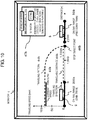
- on-board equipment 20 includes a GPS receiving section 21 that receives GPS data 11a (track data and data transmission time information) transmitted by a GPS satellite 10a, an on-board clock 22 that specifies reception time 221 of the GPS data, and an on-rail range calculating section 23 that calculates on-rail range information 231 of an own train according to GPS data 211 received by the GPS receiving section 21 and the reception time 221.
- GPS data 11a track data and data transmission time information
- on-board clock 22 that specifies reception time 221 of the GPS data
- an on-rail range calculating section 23 that calculates on-rail range information 231 of an own train according to GPS data 211 received by the GPS receiving section 21 and the reception time 221.
- the on-board equipment 20 further includes an on-board communication section 24 that performs transmission of the on-rail range information 231 to track-side equipment 30 and reception of information such as stop target information 321 transmitted from the track-side equipment 30 and a speed control section 25 that performs traveling speed control for the train according to a speed control signal 241 calculated according to the received stop target information 321.
- the track-side equipment 30 includes a track-side communication section 31 that executes transmission of on-rail range information transmitted from respective trains and transmission of the stop target information 321 to the trains and a stop target calculating section 32 that calculates stop targets of the respective trains on the basis of an on-rail range of a train traveling on the same traveling path.
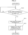
- a control flow by the on-board equipment 20 is shown in Figure 2 .
- a control flow by the track-side equipment 30 is shown in Figure 3 .
- the on-board equipment 20 checks whether a stop target is received from the track-side equipment 30 (step 9100). If a stop target is not received (No in step 9100), the on-board equipment 20 checks whether the GPS data 11a is received by the GPS receiving section 21 (step 9102). If a stop target is received (Yes in step 9100), the on-board equipment 20 specifies, from the on-board clock 22, time when the GPS receiving section 21 receives the GPS data 11a (GPS data reception time 221) (step 9103).
- the on-board equipment 20 inputs the received GPS data 211 and the GPS data reception time 221 to the on-rail range calculating section 23 (step 9104).
- the on-rail range calculating section 23 calculates on-rail range information 231 of the train according to the input data (step 9105) and transmits the on-rail range information 231 to the track-side equipment 30 through the on-board communication section 24 (step 9106).
- the track-side equipment 30 calculates stop target information 321 of the train taking into account an on-rail range of the preceding train traveling on the same traveling path (step 9201).
- the track-side equipment 30 transmits the stop target information 321 to the on-board equipment 20 through the track-side communication section 31 (step 9202).
- the on-board equipment 20 executes speed control in step 9101 and enables the own train to safely stop at the stop target.
- FIGS. 4 and 5 An image of calculation of an on-rail range by the on-rail range calculating section 23 is shown in FIGS. 4 and 5 .
- reception distance a distance from a GPS satellite 1a to the GPS receiving section 21 mounted on the on-board equipment 20 of a train 2
- reference numeral 101 corresponds to the reception distance.
- a circumference portion where a sphere having the reception distance 101 as a radius overlaps the earth's surface (the ground) is an on-rail range of the train.
- the circumference portion is calculated from track information PS (Px, Py, Pz) transmitted from the GPS satellite 1a together with the transmission time information Ts.
- a center coordinate 14a of the circumference portion is (Px, Py).
- propagation delay time Tt2 propagation delay time Tt 1 + propagation delay time Td
- propagation delay time Tt 2 propagation delay time Tt 1 + propagation delay time Td
- a circumference portion where a sphere having the pseudo-range 102 as a radius overlaps the earth's surface (the ground) is the on-rail range of the train.
- the center coordinate 14a of the circumference portion is (Px, Py).
- a ground for guaranteeing that the train is not on rails on the outer side of the on-rail range 204a is explained. It is assumed that information (track information, GPS data, transmission time, and the like) included in the GPS data received from the GPS satellite 1a is correct and time information stored by the GPS satellite 1a and time stored by a clock of the on-board equipment 20 are also correct.
- the pseudo-range 102 and the reception distance 101 are equal.
- the pseudo-range 102 is larger than the reception distance 101. This is because reception time is further delayed by the multi-path or the propagation delay in the ionosphere than a delay in reception time that occurs when the multi-path or the propagation delay Td in the ionosphere does not occur.
- the pseudo-range is larger than the reception distance and is never smaller than the reception distance.
- the circumference 204a calculated from the pseudo-range is larger the circumference 203a calculated from the reception distance by 205a. Therefore, even if the multi-path or the propagation delay in the ionosphere or the like occurs, it is guaranteed that a train is absent in a further distance than the circumference calculated from the pseudo-range, i.e., a train is always on rails within the circumference. This applies not only in the train 2.
- a circumference 504a calculated from a pseudo-range is larger than a circumference 503a calculated from a reception distance by 505a.
- the on-rail range calculating section 23 can store two-dimensional or three-dimensional map information of the railroad 6 on which the train 2 travels.
- a more accurate on-rail range can be specified by treating only a range 61 on a railroad included in the calculated on-rail range as an on-rail range using the stored map information.
- An image of calculation of an on-rail range 61 from the GPS data received from the GPS satellite 10a and the map information is shown in Figure 6 .
- the map information can also be sequentially captured from the track-side equipment 30 through radio or wire 31 to be able to follow a change in a traveling state.
- An on-rail range can also be changed according to the accuracy of the map information. For example, if the map information includes a fixed position error, a range including the error is applied as the on-rail range. Consequently, for example, it is possible to narrow the on-rail range by using detailed map information and realize high service density. On the other hand, in a low-density train line, since a detailed map is unnecessary, it is possible to reduce costs for a topography survey in creating a map.
- a train on-rail range is calculated by the on-rail range calculating section 23 shown in Figure 1 , for example, any one of a track circuit, an acceleration sensor, a gyro sensor, a tacho-generator, a transponder, a balise, radio information of a wireless LAN, an ultrasonic sensor, a Doppler radar, a camera, an infrared sensor, an axle counter is used together with the GPS to calculate the train on-rail range.
- the on-rail range calculating section 23 may use one kind of devices among the abovementioned device or may use plural kinds of devices in combination. It is also possible to properly use devices in use as appropriate according to a traveling point. Further, a position specifying technique widely used in the conventional train control and car navigation systems may be used.
- the tacho-generator is a device used for measuring a traveling distance. Errors increase in proportion to the traveling distance because of a slip during traveling, an error of a wheel diameter, and the like. Therefore, an on-rail range is calculated taking into account about several percent of the traveling distance as an error range. It is possible to grasp a more accurate on-rail range by calculating, as an on-rail range, an on-rail range calculated using GPS data and an on-rail range calculated using the tacho-generator.
- traveling speed is controlled by the speed control section 25 shown in Figure 1 , the traveling speed is calculated using at least one of an on-rail range of a train, traveling speed, a distance to a stop target, topological information (a curvature of a traveling path, a gradient, and the like), car performance (motor performance, brake performance, weight, and the like).
- topological information a curvature of a traveling path, a gradient, and the like
- car performance motor performance, brake performance, weight, and the like.
- the track-side equipment 30 can set a stop target corresponding to a change in on-rail ranges of respective trains. It is possible to perform train control corresponding to the performance of the on-rail range calculating sections 23 of the respective trains. It is also possible to control the services of the respective trains by directly exchanging on-rail ranges between trains (e.g., the train 2 and the train 5 shown in Figure 5 ) not via the track-side equipment 30.
- a stop target is calculated by the method, when propagation delay errors of GPS data in the preceding train or the own train increase because of a change in the surrounding environment or the like, in some case, a stop target shifts to behind a point of a previous stop target with respect to a traveling direction. In this case, it is assumed that the own train cannot stop before the stop target depending on a situation, an emergency brake is applied, and riding comfort and energy saving properties are markedly deteriorated.
- the stop target is not updated and the stop target at the present point in time is continuously used.
- the stop position is fixed near the entrance of the tunnel while the train is passing the tunnel.
- the stop position shifts to near the exit of the tunnel at a point in time when the train finishes passing the tunnel. If it is likely that the preceding train moves back, a point obtained by subtracting, from the stop target, a distance that the preceding train is likely to move back only has to be set as a stop target.
- the on-board equipment 20 or the track-side equipment 30 can also include a monitor 4 and include means for displaying processing situations of the devices or informing the processing situations by sound.
- the track-side equipment 30 transmits stop target information to the on-board equipment 20.
- the track-side equipment 30 may transmit speed limits of the train at respective points to the on-board equipment 20 instead of the stop target.
- the on-board equipment 20 includes the on-rail range calculating section 23.
- the track-side equipment 30 may include the on-rail range calculating section 23.
- the on-board equipment 20 transmits the GPS data 11a and the reception time information 221 of the reception by the GPS receiving section 21 to the track-side equipment 30.
- the devices e.g., the tacho-generator and the transponder
- the track-side equipment 30 inputs the information received from the on-board equipment 20 to an on-rail range calculating section 33, calculates an on-rail range 331, calculates a stop target 321 of the train taking into account an on-rail range of the preceding train traveling on the same traveling path, and transmits the on-rail range 331 and the stop target 321 to the on-board equipment 20. Processing performed thereafter is assumed to be same as the processing in the abovementioned configuration. In the configuration, since the on-board equipment 20 does not need to include the on-rail range calculating section 23, it is possible to simplify the configuration of the on-board equipment 20.
- the track-side equipment 30 grasps an on-rail range using information transmitted from the on-board equipment 20.
- the track-side equipment 30 can also calculate an on-rail range using information other than the information transmitted from the on-board equipment 20.
- the configuration is a configuration in which the information is directly input to the track-side equipment 30 not through the on-board equipment 20.
- Examples of the configuration include information input from a device located on the ground side such as a track circuit or an axle counter.
- the track-side equipment 30 calculates an on-rail range and controls a service on the basis of information acquired by the device located on the ground side other than the information input from the on-board equipment 20 of respective trains.
- train control system In the train control system explained above, as an application example, a GPS in the United States is used. However, the train control system can also be applied to other global positioning systems (e.g., Galileo in Europe, GLONASS in Russia, and Hokuto in China).
- other global positioning systems e.g., Galileo in Europe, GLONASS in Russia, and Hokuto in China.
- the track-side equipment 30 calculates a stop target.
- the on-board equipment 20 may calculate a stop target.
- the on-board equipment 20 includes the on-rail range calculating section 23 and the stop target calculating section 32.
- the on-board equipment 20 calculates an on-rail range of the own train with the on-rail range calculating section 23 and transmits the on-rail range 204a of the own train to the other train 5 traveling on the same traveling path 6.
- the on-board equipment 20 receives the on-rail range 504a from the other train 5 traveling on the same traveling path 6. If the on-rail range 504a is received from the other train 5, the on-board equipment 20 calculates the point 206 closest from the on-rail range 204a of the own train 2 as a stop target and controls the traveling speed of the own train 2.
- the on-board equipment 20 includes one GPS receiving section 21 to make it possible to receive data from one or more GPS satellites.
- the on-board equipment 20 may include plural GPS receiving sections 21 and the respective GPS receiving sections 21 may correspond to the respective GPS satellites in a one-to-one relation and receive data.
- the on-board equipment 20 including one GPS receiving section 21 may be provided for each one train car and a plurality of the train cars may be coupled to compose the train 2.
- the on-rail range calculating section 23 can also calculate an on-rail range on the basis of GPS data received by the plural GPS receiving sections 21. That can be attained by, in calculating an on-rail range on the basis of the GPS data of the plural GPS receiving sections 21, measuring locations of the respective GPS receiving sections 21 in advance and using a relative positional relation as an offset in calculating an on-rail range.
- one GPS receiving section 21 is provided at each of the leading end and the trailing end of a train having composition length of 100 meters, it is also possible to move an on-rail range, which is calculated from GPS data received by the GPS receiving section 21 at the trailing end, forward 100 meters along a traveling direction on a railroad on which the train travels, compare the on-rail range with an on-rail range calculated from GPS data received by the GPS receiving section 21 at the leading end, and set an overlapping portion as a range in which the leading end of the train is on rails.
- a circumference portion where a sphere formed by a reception distance (or a pseudo-range) overlaps the earth's ground is calculated for each of the GPS satellites and a portion where circumferences overlap one another is set as an on-rail range.
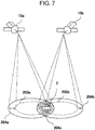
- An image of calculation of an on-rail range from GPS data received from plural satellites 1 is shown in Figure 7 . It is possible to specify a more highly accurate on-rail range by receiving track information (position information) and time information from the plural GPS satellites in this way.
- the GPS satellite originates information received from the outside of the train 2. However, this is not a limitation.
- the on-rail range calculating section 23 performs the traveling control on the basis of the GPS data received at the present point in time.
- An error change in traveling in future is not taken into account. For example, when a train passes a tunnel, a GPS data reception environment is suddenly deteriorated. Therefore, it is conceivable that an on-rail range expands and the following train needs to quickly decelerate. Conversely, when the preceding train passes the tunnel, the GPS data reception environment is suddenly improved and the on-rail range is narrowed. Therefore, quick acceleration is necessary to increase service density.
- the on-board equipment 20 or the track-side equipment 30 includes an on-rail range predicting section 34 that predicts a change in on-rail range of respective trains.
- a configuration in which the track-side equipment 30 includes the on-rail range predicting section 34 is shown in Figure 8 .
- the track-side equipment 30 predicts an on-rail range of a train at a certain point in time in future using a predicted on-rail range predicted by the on-rail range predicting section 34.
- the track-side equipment 30 calculates a predicted stop target of the train taking into account a predicted on-rail range of the preceding train traveling on the same traveling path at the same point in time and transmits the predicted stop target to the on-board equipment 20.
- the on-board equipment 20 controls traveling speed such that, at the point in time, the own train can stop at the predicted stop target safely and taking into account energy saving properties.
- the on-board equipment 20 can travel with unnecessary acceleration and deceleration suppressed by traveling while controlling speed on the basis of the predicted stop target. Consequently, the track-side equipment 30 can set a stop target to correspond to a future change in on-rail ranges of the on-board equipment 20. It is possible to perform train control with safety, service density, and energy saving properties further improved.
- a large number of methods are proposed as a method of predicting, on the basis of various kinds of information, a tendency of data that successively changes.
- a Kalman filer is used for calculating positions of a target object at respective points of time in the past, at present, and in future on the basis of sensor information.
- the on-rail range predicting section 34 can predict an on-rail range in future as well on the basis of change data of an on-rail range acquired during traveling in the past.
- the same effect can be obtained by providing, in the track-side equipment 30, a database for recording on-rail range information of respective trains collected in traveling in the past and providing the on-rail range predicting section 34 that predicts a change in an on-rail range on the basis of the recorded information.
- map information (a tunnel position, a gradient, a bending ratio, and the like) shown in Figure 6
- map information (a tunnel position, a gradient, a bending ratio, and the like) shown in Figure 6
- the same prediction effect can be obtained by providing, in the track-side equipment 30, a database for recording at least one of topological data of a traveling path, location data of a transponder, structure data (a tunnel position and the like) in the periphery, a traveling timetable, car performance data, GPS satellite data, and weather data and providing the on-rail range predicting section 34 that predicts a change in an on-rail range on the basis of the recorded information.
- train traveling is performed taking into account energy saving, it is important to reduce unnecessary acceleration and deceleration and increase coasting.
- unnecessary acceleration and deceleration increase if speed is changed following the stop target. This causes deterioration in energy saving properties. It is possible to predict fluctuation in a stop target by using the on-rail range predicting section 34. Therefore, it is possible to calculate optimum traveling speed taking into account even fluctuation of the stop target in future.
- the on-board equipment 20 or the track-side equipment 30 includes a GPS monitoring section 26 that monitors GPS data transmitted by a GPS satellite. If an error is included in information (track information, GPS data transmission time, and the like) included in the GPS data, the GPS monitoring section 26 outputs a warning to the on-board equipment 20. If the on-board equipment 20 receives the warning, the on-board equipment 20 corrects at least one of a stop target, an on-rail range, and control speed according to the error and executes notification to the track-side equipment 30 and train control.
- a GPS monitoring section 26 that monitors GPS data transmitted by a GPS satellite. If an error is included in information (track information, GPS data transmission time, and the like) included in the GPS data, the GPS monitoring section 26 outputs a warning to the on-board equipment 20. If the on-board equipment 20 receives the warning, the on-board equipment 20 corrects at least one of a stop target, an on-rail range, and control speed according to the error and executes notification to the track-side equipment 30 and train control.
- a configuration in which the on-board equipment 20 includes the GPS monitoring section 26 is shown in Figure 11 .
- a differential GPS hereinafter, DGPS
- a satellite-based augmentation system or the like is used, which is a system for providing, for example, a stationary station, which has an accurate clock and a coordinate of which is known, and improving accuracy from a difference between a position calculated from GPS reception data and the position of the stationary station.
- the on-board equipment 20 in calculating an on-rail range from the received GPS data, the on-board equipment 20 communicates with the track-side equipment 30, which stores an accurate clock, and corrects the time error of the on-board clock 22 according to accurate clock information 222 received by the on-board equipment 20.
- the track-side equipment 30 stores the accurate clock according to an NTP (Network Time Protocol), which is a communication protocol for synchronizing the DGPS or a clock of a connection apparatus to a network 70 shown in Figure 6 with accurate time.
- NTP Network Time Protocol
- the on-rail range calculating section 23 in the present invention can store a nominal error of a manufacture of the on-board clock 22 and calculate an on-rail range expanded according to a difference between the corrected time and GPS data reception time.
- the on-board clock 22 having a nominal error of ⁇ 1 ppm is used and time correction is performed after 200 milliseconds from the reception of GPS data, the on-board clock 22 shifts 1/5 million second in 200 milliseconds at the maximum. Since a radio wave travels about 60 meters in 1/500 million second, the on-rail range calculating section 23 calculates an on-rail range using a pseudo-range expanded by 60 meters.
- a conventional system for performing time correction using GPS data received from a GPS satellite which is generally adopted, may be adopted. If the GPS satellite is used, a coordinate value and corrected time at a reception point are calculated. In order to prevent a time correction error due to a propagation delay error such as a multi-path of the GPS satellite, the coordinate value of the reception point calculated from the GPS data and a coordinate value of a presence point calculated by another position estimating system such as a tacho-generator are compared and reliability of the time correction is verified on the basis of a shift between the coordinate values.
- a propagation delay error such as a multi-path of the GPS satellite
- the train is on rails in the on-rail range obtained from the GPS data. Therefore, as shown in Figure 7 , if an on-rail range is calculated using GPS data received in the same period of time by plural GPS satellites, a place where all on-rail ranges calculated from the GPS data overlap one another is always present.
- the GPS monitoring section 26 compares on-rail ranges 263 calculated from the received respective GPS data 211 and confirms that a place where all the on-rail ranges calculated from the GPS data overlap one another (e.g., 204c in Figure 7 ) is present. If at least one place where the on-rail ranges do not overlap each other is present, the GPS monitoring section 26 determines that there is an error of the GPS data or abnormality of the on-board clock 22 and outputs the error or the abnormality to the track-side equipment 30 as warning information 262. With this configuration, it is possible to instantly detect abnormality of the GPSs.
- the GPS monitoring section 26 outputs speed control information 261 to the speed control section 25 and executes deceleration of the train 2 (for changing traveling speed from 41a in Figure 9 to 41b in Figure 10 and changing a traveling pattern from 44a to 44b), a change of a stop target point (for changing the stop target point from 46a to 46b, 200 m before 46a, and changing a travelable distance from 1900 m of 45a to 1700 m of 45b).
- the GPS monitoring section 26 monitors reception information 212 (the number of reception satellites, reception sensitivity, and the like) received by the GPS receiving section 21. For example, whereas the number of GPS satellites acquired at normal time is five as indicated by 47a in Figure 9 , only three GPS satellites can be acquired at abnormal time as indicated by 47b in Figure 10 . Even in such a case, it is possible to perform the abnormality notification and the service control as explained above.
- the on-board equipment 20 or the track-side equipment 30 can grasp a state on the monitor 4. Therefore, it is possible to specify a cause of the abnormality and manually perform train service control (deceleration, a change of a stop target, and the like).
- the train control system is explained.
- the present invention is applicable to, in the same configuration, mobile control systems for airplane service control, automobile control, elevator control, and the like.
Landscapes
- Engineering & Computer Science (AREA)
- Mechanical Engineering (AREA)
- Train Traffic Observation, Control, And Security (AREA)
- Electric Propulsion And Braking For Vehicles (AREA)
Claims (10)
- Zugsteuersystem, das das Senden und Empfangen von Informationen zwischen einem Zug (2) und einem Satelliten (10a) eines globalen Positionsbestimmungssystems (GPS) erlaubt und aufgrund der Informationen einen Dienst des Zugs steuert, wobei das Zugsteuersystem Folgendes umfasst:einen Sende- und Empfangsabschnitt (21) zum Empfang von Positions-und Zeitinformationen einschließlich Positionsinformationen und Zeitinformationen von einem GPS-Satelliten;einen Zeitmessabschnitt (22) zum Messen von Informationen über eine bordeigene Zeit, wenn die Positions- und Zeitinformationen empfangen werden;einen Gleisbereichs-Berechnungsabschnitt (23, 33) zum Berechnen von Gleisbereichsinformationen des Zugs entsprechend den Positions- und Zeitinformationen und den Informationen über die bordeigene Zeit, wenn die Positions- und Zeitinformationen empfangen werden; undeinen Fahrtsteuerabschnitt (25) zum Steuern der Fahrt des Zugs, wobeidas Zugsteuersystem Start, Geschwindigkeit oder Halt der Fahrt des Zugs entsprechend den Gleisbereichsinformationen steuert,dadurch gekennzeichnet, dass der Gleisbereichs-Berechnungsabschnitt Karteninformationen einschließlich zweidimensionaler oder dreidimensionaler Positionsinformationen eines Schienenwegs, auf dem sich der Zug bewegt, verzeichnet und die Genauigkeit des Gleisbereichs unter Verwendung der Karteninformationen verbessert.
- Zugsteuersystem nach Anspruch 1, wobei der Gleisbereichs-Berechnungsabschnitt den Gleisbereich unter Verwendung von Informationen, die mittels mindestens eines Geräts unter einer Gleiskreisschaltung, einem Beschleunigungssensor, einem Gyrosensor, einem Tachogenerator, einem Transponder, einer Balise, Radiowelleninformationen eines drahtlosen LANs, einem Ultraschallsensor, einem Doppler-Radar, einer Kamera, einem Infrarotsensor und/oder einem Achszähler gewonnen werden, sowie unter Verwendung der GPS-Positions- und Zeitinformationen und der bordeigenen Zeitinformationen berechnet.
- Zugsteuersystem nach Anspruch 1 oder 2 mit einem Halteziel-Berechnungsabschnitt (32), um beim Berechnen eines Halteziels ein Halteziel bei einem letzten Berechnungspunkt zu berechnen, wenn ein Halteziel eines vorhergehenden Zugs oder des eigenen Zugs sich bezüglich einer Fahrtrichtung hinter ein Halteziel bei dem letzten Berechnungspunkt verschiebt, oder um dann, wenn sich der vorhergehenden Zug wahrscheinlich rückwärts bewegt, einen Punkt zu berechnen, der durch Subtrahieren einer Strecke, um die sich der vorhergehende Zug wahrscheinlich rückwärts bewegt, vom Halteziel gewonnen wird.
- Zugsteuersystem nach einem der vorhergehenden Ansprüche mit einem bordeigenen oder gleisseitigen Monitor (4), der Verarbeitungszustände der entsprechenden Ausrüstungsgegenstände anzeigt, oder einer Einrichtung zur Mitteilung der Arbeitszustände durch Schall.
- Zugsteuersystem nach Anspruch 1 mit bordeigener Ausrüstung, die einen Halteziel-Berechnungsabschnitt (32) beinhaltet,
wobei die bordeigene Ausrüstung außerdem den Gleisbereichs-Berechnungsabschnitt enthält, der den Gleisbereich des eigenen Zugs berechnet und den Gleisbereich an andere auf dem gleichen Fahrtweg fahrende Züge sendet und von diesen empfängt, und
wobei der Halteziel-Berechnungsabschnitt aufgrund des Gleisbereichs ein Halteziel berechnet und die Fahrtgeschwindigkeit des eigenen Zugs steuert. - Zugsteuersystem nach einem der vorhergehenden Ansprüche mit bordeigener Ausrüstung, die mehrere Empfangsgeräte für Züge einer bestimmten Zusammensetzung beinhaltet,
wobei der Gleisbereichs-Berechnungsabschnitt vorab Ortsinformationen der Empfangsgeräte verzeichnet und misst und aufgrund der von den Empfangsgeräten empfangenen Daten und der Ortsinformationen der Empfangsgeräte sowie unter Verwendung der GPS-Positions- und Zeitinformationen und der bordeigenen Zeitinformationen den Gleisbereich berechnet. - Zugsteuersystem nach einem der vorhergehenden Ansprüche mit einem bordeigenen oder gleisseitigen Gleisbereichs-Vorhersageabschnitt (34),
wobei der Gleisbereichs-Vorhersageabschnitt Gleisbereiche entsprechender Züge zu gewissen Zeitpunkten in der Zukunft vorhersagt und vorhergesagte Halteziele der Züge berechnet, wobei ein Gleisbereich eines auf dem gleichen Fahrtweg zum gleichen Zeitpunkt fahrenden vorhergehenden Zugs in Betracht gezogen wird. - Zugsteuersystem nach einem der vorhergehenden Ansprüche, außerdem umfassend:ein bordeigenes oder gleisseitiges externes Informationsüberwachungsgerät, das von außerhalb her empfangene Informationen überwacht,eine gleisseitige Uhr (35), undeine gleisseitige Einrichtung zum Vorab-Verzeichnen eines Orts einer gleisseitigen Ausrüstung und zum Erfassen mindestens einer Art von Informationen aus Positionsinformationen und einer externen Datensendezeit unter Informationen, die in durch ein externes Empfangsgerät empfangenen externen Daten enthalten sind, und zum Ausgeben einer Warnung an eine bordeigene Ausrüstung, wenn ein Fehler der externen Daten erkannt wird.
- Zugsteuersystem nach einem der vorhergehenden Ansprüche, wobei das Zugsteuersystem zum Korrigieren eines Zeitfehlers in dem Zeitmessabschnitt einen Koordinatenwert und eine Korrekturzeit eines Gleispunkts, der aus externen Daten berechnet wird, und einen Gleispunkt vergleicht, der aus Informationen berechnet wird, die mittels mindestens eines Geräts unter einem Gleiskreisschaltung, einem Beschleunigungssensor, einem Gyrosensor, einem Tachogenerator, einem Transponder, einer Balise, Radiowelleninformationen eines drahtlosen LANs, einem Ultraschallsensor, einem Doppler-Radar, einer Kamera, einem Infrarotsensor und/oder einem Achszähler gewonnen werden, und die Zuverlässigkeit der Zeitkorrektur aufgrund einer Verschiebung zwischen dem Koordinatenwert und der Korrekturzeit und dem Gleispunkt überprüft.
- Zugsteuersystem nach Anspruch 8, wobei das externe Informations-Überwachungsgerät aus den externen Daten berechnete Gleisbereiche vergleicht, verifiziert, dass ein Ort vorliegt, an dem all die aus den externen Daten berechneten Gleisbereiche einander überlappen, und dann, wenn der Ort fehlt, an dem all die Gleisbereiche einander überlappen, bestimmt, dass unter den in den externen Daten enthaltenen Informationen ein Fehler bei mindestens einer Art von Information aus den Ortsinformationen und/oder der Datensendezeit vorliegt oder dass eine Abnormität des Zeitmessabschnitts vorliegt, und an eine bordeigene Ausrüstung eine Warnung ausgibt.
Applications Claiming Priority (1)
| Application Number | Priority Date | Filing Date | Title |
|---|---|---|---|
| JP2011158975A JP5373861B2 (ja) | 2011-07-20 | 2011-07-20 | 列車制御システム |
Publications (3)
| Publication Number | Publication Date |
|---|---|
| EP2548784A2 EP2548784A2 (de) | 2013-01-23 |
| EP2548784A3 EP2548784A3 (de) | 2016-07-13 |
| EP2548784B1 true EP2548784B1 (de) | 2018-04-11 |
Family
ID=46548303
Family Applications (1)
| Application Number | Title | Priority Date | Filing Date |
|---|---|---|---|
| EP12177162.0A Not-in-force EP2548784B1 (de) | 2011-07-20 | 2012-07-19 | Zugsteuersystem |
Country Status (5)
| Country | Link |
|---|---|
| EP (1) | EP2548784B1 (de) |
| JP (1) | JP5373861B2 (de) |
| CN (1) | CN102887150B (de) |
| IN (1) | IN2012DE02209A (de) |
| RU (1) | RU2536271C2 (de) |
Families Citing this family (31)
| Publication number | Priority date | Publication date | Assignee | Title |
|---|---|---|---|---|
| JP6296716B2 (ja) | 2013-07-19 | 2018-03-20 | 株式会社東芝 | 運転曲線作成装置、運転曲線作成装置の制御方法及び制御プログラム |
| CN103723165A (zh) * | 2014-01-23 | 2014-04-16 | 黑龙江精达信息技术有限责任公司 | 城市轨道交通安全智能监控装置及监控方法 |
| JP2015189361A (ja) * | 2014-03-28 | 2015-11-02 | 公益財団法人鉄道総合技術研究所 | 無線列車制御方法および無線列車制御システム |
| JP6420972B2 (ja) * | 2014-06-13 | 2018-11-07 | 公益財団法人鉄道総合技術研究所 | 列車制御システム設計用シミュレータ |
| CN104408972A (zh) * | 2014-12-02 | 2015-03-11 | 合肥工大高科信息科技股份有限公司 | 一种基于dgps的矿用车辆防碰撞装置及其控制方法 |
| JP6239160B2 (ja) | 2015-01-28 | 2017-11-29 | 三菱電機株式会社 | 列車位置検知装置 |
| JP6310868B2 (ja) * | 2015-02-12 | 2018-04-11 | 株式会社日立製作所 | 進路制御システム、進路制御方法、及び地上装置 |
| JP6504560B2 (ja) * | 2015-03-02 | 2019-04-24 | 大同信号株式会社 | 無線式鉄道制御システム及び地上装置 |
| WO2016166879A1 (ja) * | 2015-04-17 | 2016-10-20 | 株式会社日立製作所 | 鉄道運行管理システム |
| WO2017145575A1 (ja) | 2016-02-24 | 2017-08-31 | 三菱電機株式会社 | 衛星測位装置及び列車制御システム |
| JP6801995B2 (ja) * | 2016-07-26 | 2020-12-16 | 株式会社日立製作所 | 列車定位置停止制御装置およびそれを搭載した鉄道車両 |
| DE102016215767A1 (de) * | 2016-08-23 | 2018-03-01 | Siemens Aktiengesellschaft | Vorhersage des Zuglaufs |
| JP6846946B2 (ja) | 2017-02-24 | 2021-03-24 | 三菱重工エンジニアリング株式会社 | 車両制御装置、車両制御方法、プログラム |
| CN109298656B (zh) * | 2017-07-24 | 2020-07-14 | 株洲中车时代电气股份有限公司 | 一种机车车辆远程监视系统及方法 |
| EP3683085A4 (de) * | 2017-09-15 | 2021-06-09 | Hitachi, Ltd. | Zugsteuerungssystem |
| CN109552361B (zh) * | 2018-10-31 | 2020-09-04 | 交控科技股份有限公司 | 一种互联互通跨线的轨旁设备模拟方法及系统 |
| CN109878555B (zh) * | 2019-01-28 | 2021-06-08 | 卡斯柯信号有限公司 | 一种基于无源应答器的列车控制方法 |
| WO2021116944A1 (en) | 2019-12-09 | 2021-06-17 | Thales Canada Inc. | Stationary status resolution system |
| DE102020204195A1 (de) * | 2020-03-31 | 2021-09-30 | Siemens Mobility GmbH | Verfahren zur Positionsüberwachung eines abgestellten Schienenfahrzeugs und Computerprogramm, insbesondere für Zugsicherungssystem |
| CN111929670B (zh) * | 2020-07-28 | 2023-12-29 | 胡运成 | 一种轨道交通列车速度测量方法及系统 |
| CN112308976A (zh) * | 2020-10-28 | 2021-02-02 | 上海恒润数字科技集团股份有限公司 | 一种轨道车及其执行控制机构的误差控制方法和装置 |
| JP7229433B2 (ja) * | 2021-02-26 | 2023-02-27 | 三菱電機株式会社 | 状態監視装置、地上無線装置、車上無線装置、障害リスク判定方法、制御回路および記憶媒体 |
| TWI850559B (zh) * | 2021-05-24 | 2024-08-01 | 中華電信股份有限公司 | 鐵道偵測之物聯網系統、方法及電腦可讀媒介 |
| CN113401170B (zh) * | 2021-06-28 | 2023-05-16 | 通号城市轨道交通技术有限公司 | 列车自主运行系统下的移动授权方法及系统 |
| CN113548094B (zh) * | 2021-07-28 | 2023-08-18 | 通号城市轨道交通技术有限公司 | 基于多传感器的列车定位、联挂方法及系统 |
| CN113978519A (zh) * | 2021-12-03 | 2022-01-28 | 同济大学 | 轨道交通列车运行控制系统北斗时间同步方法和系统 |
| JP7747880B2 (ja) * | 2022-03-31 | 2025-10-01 | 株式会社日立製作所 | 列車制御システムおよび列車制御方法 |
| CN115635989B (zh) * | 2022-11-01 | 2025-03-07 | 交控科技股份有限公司 | 轨道列车运行控制方法及轨道列车 |
| CN115848460B (zh) * | 2023-01-29 | 2023-05-12 | 北京全路通信信号研究设计院集团有限公司 | 一种半自动闭塞线路的信号授权方法及系统 |
| CN116108702B (zh) * | 2023-04-11 | 2023-07-11 | 卡斯柯信号(北京)有限公司 | 列控系统完全模式下接收临时限速的测试方法及装置 |
| CN116811971B (zh) * | 2023-07-27 | 2024-02-20 | 江苏飞梭智行设备有限公司 | 一种轨道车安全控制系统 |
Family Cites Families (23)
| Publication number | Priority date | Publication date | Assignee | Title |
|---|---|---|---|---|
| JPH06331373A (ja) * | 1993-05-26 | 1994-12-02 | Alpine Electron Inc | 車両位置検出方法 |
| JP3431430B2 (ja) * | 1996-12-12 | 2003-07-28 | 株式会社日立製作所 | 列車情報伝送方法、列車速度制御方法および列車制御システム |
| JP2002027617A (ja) * | 2000-07-11 | 2002-01-25 | Nippon Signal Co Ltd:The | 列車走行制御システム、及び列車走行制御方法 |
| JP2002225708A (ja) * | 2001-02-01 | 2002-08-14 | Omron Corp | 位置検出装置および情報処理装置、並びに位置検出システム |
| JP4490606B2 (ja) * | 2001-08-03 | 2010-06-30 | 東芝トランスポートエンジニアリング株式会社 | 列車運行制御装置 |
| US7209810B2 (en) * | 2002-01-10 | 2007-04-24 | Lockheed Martin Corp. | Locomotive location system and method |
| AUPS123702A0 (en) * | 2002-03-22 | 2002-04-18 | Nahla, Ibrahim S. Mr | The train navigtion and control system (TNCS) for multiple tracks |
| JP3854528B2 (ja) * | 2002-04-11 | 2006-12-06 | 株式会社京三製作所 | 列車制御システム、及び、列車制御方法 |
| JP4090852B2 (ja) * | 2002-11-21 | 2008-05-28 | 財団法人鉄道総合技術研究所 | Gps測位による列車走行情報検出装置及びその列車走行情報検出方法 |
| JP4087786B2 (ja) * | 2003-12-19 | 2008-05-21 | 株式会社日立製作所 | 列車位置検知方法 |
| JP4454303B2 (ja) * | 2003-12-22 | 2010-04-21 | 株式会社日立製作所 | 信号保安システム |
| JP2006098246A (ja) * | 2004-09-30 | 2006-04-13 | Nippon Seiki Co Ltd | 車両位置検出装置 |
| JP2006136041A (ja) * | 2004-11-02 | 2006-05-25 | Kyosan Electric Mfg Co Ltd | 列車停止制御装置 |
| JP4714490B2 (ja) * | 2005-03-18 | 2011-06-29 | 北海道旅客鉄道株式会社 | 車載装置及び運行管理装置 |
| US7522990B2 (en) * | 2005-06-08 | 2009-04-21 | General Electric Company | System and method for improved train handling and fuel consumption |
| US8370006B2 (en) * | 2006-03-20 | 2013-02-05 | General Electric Company | Method and apparatus for optimizing a train trip using signal information |
| JP5185575B2 (ja) * | 2007-08-10 | 2013-04-17 | 川崎重工業株式会社 | 列車の自車位置検出装置、車体傾斜制御システム、操舵システム、アクティブ制振システム及びセミアクティブ制振システム |
| JP2010120484A (ja) | 2008-11-19 | 2010-06-03 | Hitachi Ltd | 列車停止制御システム |
| RU85434U1 (ru) * | 2009-04-13 | 2009-08-10 | Открытое акционерное общество "Российские железные дороги" (ОАО "РЖД") | Система управления движением поездов на однопутной железной дороге с двухпутными вставками |
| JP2010284983A (ja) * | 2009-06-09 | 2010-12-24 | Mitsubishi Electric Corp | 鉄道車両用時刻補正装置、鉄道車両時刻補正用gps時計および鉄道車両用時刻補正方法 |
| JP5377260B2 (ja) * | 2009-12-10 | 2013-12-25 | 株式会社京三製作所 | 列車制御装置 |
| JP5398500B2 (ja) * | 2009-12-10 | 2014-01-29 | 株式会社京三製作所 | 列車制御装置 |
| RU94939U1 (ru) * | 2010-03-01 | 2010-06-10 | Открытое акционерное общество "Научно-исследовательский и проектно-конструкторский институт информатизации, автоматизации и связи на железнодорожном транспорте" (ОАО "НИИАС") | Система контроля и управления скоростным электропоездом |
-
2011
- 2011-07-20 JP JP2011158975A patent/JP5373861B2/ja not_active Expired - Fee Related
-
2012
- 2012-07-16 CN CN201210245778.XA patent/CN102887150B/zh not_active Expired - Fee Related
- 2012-07-17 IN IN2209DE2012 patent/IN2012DE02209A/en unknown
- 2012-07-19 EP EP12177162.0A patent/EP2548784B1/de not_active Not-in-force
- 2012-07-19 RU RU2012130863/11A patent/RU2536271C2/ru active
Non-Patent Citations (1)
| Title |
|---|
| None * |
Also Published As
| Publication number | Publication date |
|---|---|
| RU2536271C2 (ru) | 2014-12-20 |
| CN102887150B (zh) | 2015-06-24 |
| JP5373861B2 (ja) | 2013-12-18 |
| EP2548784A2 (de) | 2013-01-23 |
| CN102887150A (zh) | 2013-01-23 |
| RU2012130863A (ru) | 2014-01-27 |
| JP2013023054A (ja) | 2013-02-04 |
| IN2012DE02209A (de) | 2015-09-25 |
| EP2548784A3 (de) | 2016-07-13 |
Similar Documents
| Publication | Publication Date | Title |
|---|---|---|
| EP2548784B1 (de) | Zugsteuersystem | |
| CN103221291B (zh) | 对位置的估计的完整性进行实时检测的用于定位列车的系统 | |
| ES2673851T3 (es) | Conducción de vehículos en convoy | |
| JP5619632B2 (ja) | 移動体制御システム | |
| US20090043435A1 (en) | Methods and systems for making a gps signal vital | |
| EP2762381B1 (de) | Zugsteuersystem | |
| CN110972066A (zh) | 列车及其安全定位系统 | |
| US20140100713A1 (en) | Gnss/imu positioning, communication, and computation platforms for automotive safety applications | |
| JP2010234979A (ja) | 鉄道車両の運転保安システムにおける位置検出装置およびその位置検出方法 | |
| JP5506762B2 (ja) | 車上装置および列車位置計算方法 | |
| EP2614983A2 (de) | Zugsteuersystem | |
| JP6544415B2 (ja) | 衛星測位利用車両用制御システムの制御方法 | |
| CN104973093A (zh) | 计算铁路车辆在铁路轨道上的位置范围的方法及相关装置 | |
| JP2008247217A (ja) | 列車位置検知装置 | |
| Neri et al. | A train integrity solution based on GNSS double-difference approach | |
| JP4548604B2 (ja) | 車車間通信システム | |
| KR101262762B1 (ko) | 열차의 위치 오차 보정 장치 및 방법 | |
| KR102687315B1 (ko) | 열차 제어 시스템 | |
| JP2007284013A (ja) | 車両位置測位装置及び車両位置測位方法 | |
| JP6534701B2 (ja) | 位置検出システム | |
| Neri | Train control and rail traffic management systems | |
| RU2763015C1 (ru) | Способ и система децентрализованного интервального регулирования движения поездов | |
| US20250060486A1 (en) | Device and method for autonomous positioning of vehicles | |
| CN115812226B (zh) | 交互式车辆交通运输网络的系统和方法 | |
| JP2010234978A (ja) | 鉄道車両の速度照査式の運転保安システムにおける速度検出装置およびその速度検出方法 |
Legal Events
| Date | Code | Title | Description |
|---|---|---|---|
| PUAI | Public reference made under article 153(3) epc to a published international application that has entered the european phase |
Free format text: ORIGINAL CODE: 0009012 |
|
| 17P | Request for examination filed |
Effective date: 20120806 |
|
| AK | Designated contracting states |
Kind code of ref document: A2 Designated state(s): AL AT BE BG CH CY CZ DE DK EE ES FI FR GB GR HR HU IE IS IT LI LT LU LV MC MK MT NL NO PL PT RO RS SE SI SK SM TR |
|
| AX | Request for extension of the european patent |
Extension state: BA ME |
|
| PUAL | Search report despatched |
Free format text: ORIGINAL CODE: 0009013 |
|
| AK | Designated contracting states |
Kind code of ref document: A3 Designated state(s): AL AT BE BG CH CY CZ DE DK EE ES FI FR GB GR HR HU IE IS IT LI LT LU LV MC MK MT NL NO PL PT RO RS SE SI SK SM TR |
|
| AX | Request for extension of the european patent |
Extension state: BA ME |
|
| RIC1 | Information provided on ipc code assigned before grant |
Ipc: B61L 25/02 20060101AFI20160607BHEP Ipc: B61L 27/00 20060101ALI20160607BHEP |
|
| 17Q | First examination report despatched |
Effective date: 20170412 |
|
| GRAP | Despatch of communication of intention to grant a patent |
Free format text: ORIGINAL CODE: EPIDOSNIGR1 |
|
| INTG | Intention to grant announced |
Effective date: 20171222 |
|
| GRAS | Grant fee paid |
Free format text: ORIGINAL CODE: EPIDOSNIGR3 |
|
| GRAA | (expected) grant |
Free format text: ORIGINAL CODE: 0009210 |
|
| AK | Designated contracting states |
Kind code of ref document: B1 Designated state(s): AL AT BE BG CH CY CZ DE DK EE ES FI FR GB GR HR HU IE IS IT LI LT LU LV MC MK MT NL NO PL PT RO RS SE SI SK SM TR |
|
| REG | Reference to a national code |
Ref country code: GB Ref legal event code: FG4D |
|
| REG | Reference to a national code |
Ref country code: CH Ref legal event code: EP |
|
| REG | Reference to a national code |
Ref country code: AT Ref legal event code: REF Ref document number: 987695 Country of ref document: AT Kind code of ref document: T Effective date: 20180415 |
|
| REG | Reference to a national code |
Ref country code: IE Ref legal event code: FG4D |
|
| REG | Reference to a national code |
Ref country code: DE Ref legal event code: R096 Ref document number: 602012044977 Country of ref document: DE |
|
| REG | Reference to a national code |
Ref country code: NL Ref legal event code: MP Effective date: 20180411 |
|
| REG | Reference to a national code |
Ref country code: LT Ref legal event code: MG4D |
|
| PG25 | Lapsed in a contracting state [announced via postgrant information from national office to epo] |
Ref country code: NL Free format text: LAPSE BECAUSE OF FAILURE TO SUBMIT A TRANSLATION OF THE DESCRIPTION OR TO PAY THE FEE WITHIN THE PRESCRIBED TIME-LIMIT Effective date: 20180411 |
|
| PG25 | Lapsed in a contracting state [announced via postgrant information from national office to epo] |
Ref country code: ES Free format text: LAPSE BECAUSE OF FAILURE TO SUBMIT A TRANSLATION OF THE DESCRIPTION OR TO PAY THE FEE WITHIN THE PRESCRIBED TIME-LIMIT Effective date: 20180411 Ref country code: AL Free format text: LAPSE BECAUSE OF FAILURE TO SUBMIT A TRANSLATION OF THE DESCRIPTION OR TO PAY THE FEE WITHIN THE PRESCRIBED TIME-LIMIT Effective date: 20180411 Ref country code: SE Free format text: LAPSE BECAUSE OF FAILURE TO SUBMIT A TRANSLATION OF THE DESCRIPTION OR TO PAY THE FEE WITHIN THE PRESCRIBED TIME-LIMIT Effective date: 20180411 Ref country code: LT Free format text: LAPSE BECAUSE OF FAILURE TO SUBMIT A TRANSLATION OF THE DESCRIPTION OR TO PAY THE FEE WITHIN THE PRESCRIBED TIME-LIMIT Effective date: 20180411 Ref country code: PL Free format text: LAPSE BECAUSE OF FAILURE TO SUBMIT A TRANSLATION OF THE DESCRIPTION OR TO PAY THE FEE WITHIN THE PRESCRIBED TIME-LIMIT Effective date: 20180411 Ref country code: FI Free format text: LAPSE BECAUSE OF FAILURE TO SUBMIT A TRANSLATION OF THE DESCRIPTION OR TO PAY THE FEE WITHIN THE PRESCRIBED TIME-LIMIT Effective date: 20180411 Ref country code: NO Free format text: LAPSE BECAUSE OF FAILURE TO SUBMIT A TRANSLATION OF THE DESCRIPTION OR TO PAY THE FEE WITHIN THE PRESCRIBED TIME-LIMIT Effective date: 20180711 Ref country code: BG Free format text: LAPSE BECAUSE OF FAILURE TO SUBMIT A TRANSLATION OF THE DESCRIPTION OR TO PAY THE FEE WITHIN THE PRESCRIBED TIME-LIMIT Effective date: 20180711 |
|
| PG25 | Lapsed in a contracting state [announced via postgrant information from national office to epo] |
Ref country code: RS Free format text: LAPSE BECAUSE OF FAILURE TO SUBMIT A TRANSLATION OF THE DESCRIPTION OR TO PAY THE FEE WITHIN THE PRESCRIBED TIME-LIMIT Effective date: 20180411 Ref country code: LV Free format text: LAPSE BECAUSE OF FAILURE TO SUBMIT A TRANSLATION OF THE DESCRIPTION OR TO PAY THE FEE WITHIN THE PRESCRIBED TIME-LIMIT Effective date: 20180411 Ref country code: GR Free format text: LAPSE BECAUSE OF FAILURE TO SUBMIT A TRANSLATION OF THE DESCRIPTION OR TO PAY THE FEE WITHIN THE PRESCRIBED TIME-LIMIT Effective date: 20180712 Ref country code: HR Free format text: LAPSE BECAUSE OF FAILURE TO SUBMIT A TRANSLATION OF THE DESCRIPTION OR TO PAY THE FEE WITHIN THE PRESCRIBED TIME-LIMIT Effective date: 20180411 |
|
| REG | Reference to a national code |
Ref country code: AT Ref legal event code: MK05 Ref document number: 987695 Country of ref document: AT Kind code of ref document: T Effective date: 20180411 |
|
| PG25 | Lapsed in a contracting state [announced via postgrant information from national office to epo] |
Ref country code: PT Free format text: LAPSE BECAUSE OF FAILURE TO SUBMIT A TRANSLATION OF THE DESCRIPTION OR TO PAY THE FEE WITHIN THE PRESCRIBED TIME-LIMIT Effective date: 20180813 |
|
| REG | Reference to a national code |
Ref country code: DE Ref legal event code: R097 Ref document number: 602012044977 Country of ref document: DE |
|
| PG25 | Lapsed in a contracting state [announced via postgrant information from national office to epo] |
Ref country code: SK Free format text: LAPSE BECAUSE OF FAILURE TO SUBMIT A TRANSLATION OF THE DESCRIPTION OR TO PAY THE FEE WITHIN THE PRESCRIBED TIME-LIMIT Effective date: 20180411 Ref country code: EE Free format text: LAPSE BECAUSE OF FAILURE TO SUBMIT A TRANSLATION OF THE DESCRIPTION OR TO PAY THE FEE WITHIN THE PRESCRIBED TIME-LIMIT Effective date: 20180411 Ref country code: DK Free format text: LAPSE BECAUSE OF FAILURE TO SUBMIT A TRANSLATION OF THE DESCRIPTION OR TO PAY THE FEE WITHIN THE PRESCRIBED TIME-LIMIT Effective date: 20180411 Ref country code: AT Free format text: LAPSE BECAUSE OF FAILURE TO SUBMIT A TRANSLATION OF THE DESCRIPTION OR TO PAY THE FEE WITHIN THE PRESCRIBED TIME-LIMIT Effective date: 20180411 Ref country code: CZ Free format text: LAPSE BECAUSE OF FAILURE TO SUBMIT A TRANSLATION OF THE DESCRIPTION OR TO PAY THE FEE WITHIN THE PRESCRIBED TIME-LIMIT Effective date: 20180411 Ref country code: RO Free format text: LAPSE BECAUSE OF FAILURE TO SUBMIT A TRANSLATION OF THE DESCRIPTION OR TO PAY THE FEE WITHIN THE PRESCRIBED TIME-LIMIT Effective date: 20180411 |
|
| PLBE | No opposition filed within time limit |
Free format text: ORIGINAL CODE: 0009261 |
|
| STAA | Information on the status of an ep patent application or granted ep patent |
Free format text: STATUS: NO OPPOSITION FILED WITHIN TIME LIMIT |
|
| PG25 | Lapsed in a contracting state [announced via postgrant information from national office to epo] |
Ref country code: IT Free format text: LAPSE BECAUSE OF FAILURE TO SUBMIT A TRANSLATION OF THE DESCRIPTION OR TO PAY THE FEE WITHIN THE PRESCRIBED TIME-LIMIT Effective date: 20180411 Ref country code: SM Free format text: LAPSE BECAUSE OF FAILURE TO SUBMIT A TRANSLATION OF THE DESCRIPTION OR TO PAY THE FEE WITHIN THE PRESCRIBED TIME-LIMIT Effective date: 20180411 |
|
| REG | Reference to a national code |
Ref country code: CH Ref legal event code: PL |
|
| 26N | No opposition filed |
Effective date: 20190114 |
|
| PG25 | Lapsed in a contracting state [announced via postgrant information from national office to epo] |
Ref country code: MC Free format text: LAPSE BECAUSE OF FAILURE TO SUBMIT A TRANSLATION OF THE DESCRIPTION OR TO PAY THE FEE WITHIN THE PRESCRIBED TIME-LIMIT Effective date: 20180411 Ref country code: LU Free format text: LAPSE BECAUSE OF NON-PAYMENT OF DUE FEES Effective date: 20180719 |
|
| REG | Reference to a national code |
Ref country code: BE Ref legal event code: MM Effective date: 20180731 |
|
| REG | Reference to a national code |
Ref country code: IE Ref legal event code: MM4A |
|
| PG25 | Lapsed in a contracting state [announced via postgrant information from national office to epo] |
Ref country code: FR Free format text: LAPSE BECAUSE OF NON-PAYMENT OF DUE FEES Effective date: 20180731 Ref country code: LI Free format text: LAPSE BECAUSE OF NON-PAYMENT OF DUE FEES Effective date: 20180731 Ref country code: CH Free format text: LAPSE BECAUSE OF NON-PAYMENT OF DUE FEES Effective date: 20180731 Ref country code: IE Free format text: LAPSE BECAUSE OF NON-PAYMENT OF DUE FEES Effective date: 20180719 |
|
| PG25 | Lapsed in a contracting state [announced via postgrant information from national office to epo] |
Ref country code: BE Free format text: LAPSE BECAUSE OF NON-PAYMENT OF DUE FEES Effective date: 20180731 Ref country code: SI Free format text: LAPSE BECAUSE OF FAILURE TO SUBMIT A TRANSLATION OF THE DESCRIPTION OR TO PAY THE FEE WITHIN THE PRESCRIBED TIME-LIMIT Effective date: 20180411 |
|
| PG25 | Lapsed in a contracting state [announced via postgrant information from national office to epo] |
Ref country code: MT Free format text: LAPSE BECAUSE OF NON-PAYMENT OF DUE FEES Effective date: 20180719 |
|
| PG25 | Lapsed in a contracting state [announced via postgrant information from national office to epo] |
Ref country code: TR Free format text: LAPSE BECAUSE OF FAILURE TO SUBMIT A TRANSLATION OF THE DESCRIPTION OR TO PAY THE FEE WITHIN THE PRESCRIBED TIME-LIMIT Effective date: 20180411 |
|
| PG25 | Lapsed in a contracting state [announced via postgrant information from national office to epo] |
Ref country code: HU Free format text: LAPSE BECAUSE OF FAILURE TO SUBMIT A TRANSLATION OF THE DESCRIPTION OR TO PAY THE FEE WITHIN THE PRESCRIBED TIME-LIMIT; INVALID AB INITIO Effective date: 20120719 |
|
| PG25 | Lapsed in a contracting state [announced via postgrant information from national office to epo] |
Ref country code: CY Free format text: LAPSE BECAUSE OF FAILURE TO SUBMIT A TRANSLATION OF THE DESCRIPTION OR TO PAY THE FEE WITHIN THE PRESCRIBED TIME-LIMIT Effective date: 20180411 Ref country code: MK Free format text: LAPSE BECAUSE OF NON-PAYMENT OF DUE FEES Effective date: 20180411 |
|
| PG25 | Lapsed in a contracting state [announced via postgrant information from national office to epo] |
Ref country code: IS Free format text: LAPSE BECAUSE OF FAILURE TO SUBMIT A TRANSLATION OF THE DESCRIPTION OR TO PAY THE FEE WITHIN THE PRESCRIBED TIME-LIMIT Effective date: 20180811 |
|
| PGFP | Annual fee paid to national office [announced via postgrant information from national office to epo] |
Ref country code: GB Payment date: 20220606 Year of fee payment: 11 |
|
| PGFP | Annual fee paid to national office [announced via postgrant information from national office to epo] |
Ref country code: DE Payment date: 20220531 Year of fee payment: 11 |
|
| REG | Reference to a national code |
Ref country code: DE Ref legal event code: R119 Ref document number: 602012044977 Country of ref document: DE |
|
| GBPC | Gb: european patent ceased through non-payment of renewal fee |
Effective date: 20230719 |
|
| PG25 | Lapsed in a contracting state [announced via postgrant information from national office to epo] |
Ref country code: DE Free format text: LAPSE BECAUSE OF NON-PAYMENT OF DUE FEES Effective date: 20240201 Ref country code: GB Free format text: LAPSE BECAUSE OF NON-PAYMENT OF DUE FEES Effective date: 20230719 |