EP2546846A1 - Schlauchverschluss - Google Patents
Schlauchverschluss Download PDFInfo
- Publication number
- EP2546846A1 EP2546846A1 EP12005119A EP12005119A EP2546846A1 EP 2546846 A1 EP2546846 A1 EP 2546846A1 EP 12005119 A EP12005119 A EP 12005119A EP 12005119 A EP12005119 A EP 12005119A EP 2546846 A1 EP2546846 A1 EP 2546846A1
- Authority
- EP
- European Patent Office
- Prior art keywords
- hose
- insert
- closure
- hollow body
- elastomeric
- Prior art date
- Legal status (The legal status is an assumption and is not a legal conclusion. Google has not performed a legal analysis and makes no representation as to the accuracy of the status listed.)
- Granted
Links
Images


Classifications
-
- B—PERFORMING OPERATIONS; TRANSPORTING
- B60—VEHICLES IN GENERAL
- B60J—WINDOWS, WINDSCREENS, NON-FIXED ROOFS, DOORS, OR SIMILAR DEVICES FOR VEHICLES; REMOVABLE EXTERNAL PROTECTIVE COVERINGS SPECIALLY ADAPTED FOR VEHICLES
- B60J10/00—Sealing arrangements
-
- B—PERFORMING OPERATIONS; TRANSPORTING
- B29—WORKING OF PLASTICS; WORKING OF SUBSTANCES IN A PLASTIC STATE IN GENERAL
- B29C—SHAPING OR JOINING OF PLASTICS; SHAPING OF MATERIAL IN A PLASTIC STATE, NOT OTHERWISE PROVIDED FOR; AFTER-TREATMENT OF THE SHAPED PRODUCTS, e.g. REPAIRING
- B29C45/00—Injection moulding, i.e. forcing the required volume of moulding material through a nozzle into a closed mould; Apparatus therefor
- B29C45/14—Injection moulding, i.e. forcing the required volume of moulding material through a nozzle into a closed mould; Apparatus therefor incorporating preformed parts or layers, e.g. injection moulding around inserts or for coating articles
- B29C45/14336—Coating a portion of the article, e.g. the edge of the article
-
- B—PERFORMING OPERATIONS; TRANSPORTING
- B29—WORKING OF PLASTICS; WORKING OF SUBSTANCES IN A PLASTIC STATE IN GENERAL
- B29C—SHAPING OR JOINING OF PLASTICS; SHAPING OF MATERIAL IN A PLASTIC STATE, NOT OTHERWISE PROVIDED FOR; AFTER-TREATMENT OF THE SHAPED PRODUCTS, e.g. REPAIRING
- B29C45/00—Injection moulding, i.e. forcing the required volume of moulding material through a nozzle into a closed mould; Apparatus therefor
- B29C45/14—Injection moulding, i.e. forcing the required volume of moulding material through a nozzle into a closed mould; Apparatus therefor incorporating preformed parts or layers, e.g. injection moulding around inserts or for coating articles
- B29C45/14598—Coating tubular articles
-
- B—PERFORMING OPERATIONS; TRANSPORTING
- B60—VEHICLES IN GENERAL
- B60J—WINDOWS, WINDSCREENS, NON-FIXED ROOFS, DOORS, OR SIMILAR DEVICES FOR VEHICLES; REMOVABLE EXTERNAL PROTECTIVE COVERINGS SPECIALLY ADAPTED FOR VEHICLES
- B60J10/00—Sealing arrangements
- B60J10/20—Sealing arrangements characterised by the shape
- B60J10/24—Sealing arrangements characterised by the shape having tubular parts
-
- H—ELECTRICITY
- H01—ELECTRIC ELEMENTS
- H01H—ELECTRIC SWITCHES; RELAYS; SELECTORS; EMERGENCY PROTECTIVE DEVICES
- H01H3/00—Mechanisms for operating contacts
- H01H3/02—Operating parts, i.e. for operating driving mechanism by a mechanical force external to the switch
- H01H3/14—Operating parts, i.e. for operating driving mechanism by a mechanical force external to the switch adapted for operation by a part of the human body other than the hand, e.g. by foot
- H01H3/141—Cushion or mat switches
- H01H3/142—Cushion or mat switches of the elongated strip type
-
- B—PERFORMING OPERATIONS; TRANSPORTING
- B29—WORKING OF PLASTICS; WORKING OF SUBSTANCES IN A PLASTIC STATE IN GENERAL
- B29C—SHAPING OR JOINING OF PLASTICS; SHAPING OF MATERIAL IN A PLASTIC STATE, NOT OTHERWISE PROVIDED FOR; AFTER-TREATMENT OF THE SHAPED PRODUCTS, e.g. REPAIRING
- B29C45/00—Injection moulding, i.e. forcing the required volume of moulding material through a nozzle into a closed mould; Apparatus therefor
- B29C45/14—Injection moulding, i.e. forcing the required volume of moulding material through a nozzle into a closed mould; Apparatus therefor incorporating preformed parts or layers, e.g. injection moulding around inserts or for coating articles
- B29C45/14065—Positioning or centering articles in the mould
-
- B—PERFORMING OPERATIONS; TRANSPORTING
- B29—WORKING OF PLASTICS; WORKING OF SUBSTANCES IN A PLASTIC STATE IN GENERAL
- B29K—INDEXING SCHEME ASSOCIATED WITH SUBCLASSES B29B, B29C OR B29D, RELATING TO MOULDING MATERIALS OR TO MATERIALS FOR MOULDS, REINFORCEMENTS, FILLERS OR PREFORMED PARTS, e.g. INSERTS
- B29K2023/00—Use of polyalkenes or derivatives thereof as moulding material
- B29K2023/16—EPM, i.e. ethylene-propylene copolymers; EPDM, i.e. ethylene-propylene-diene copolymers; EPT, i.e. ethylene-propylene terpolymers
-
- H—ELECTRICITY
- H01—ELECTRIC ELEMENTS
- H01H—ELECTRIC SWITCHES; RELAYS; SELECTORS; EMERGENCY PROTECTIVE DEVICES
- H01H13/00—Switches having rectilinearly-movable operating part or parts adapted for pushing or pulling in one direction only, e.g. push-button switch
- H01H13/02—Details
- H01H13/12—Movable parts; Contacts mounted thereon
- H01H13/14—Operating parts, e.g. push-button
- H01H13/16—Operating parts, e.g. push-button adapted for operation by a part of the human body other than the hand, e.g. by foot
-
- H—ELECTRICITY
- H01—ELECTRIC ELEMENTS
- H01H—ELECTRIC SWITCHES; RELAYS; SELECTORS; EMERGENCY PROTECTIVE DEVICES
- H01H35/00—Switches operated by change of a physical condition
- H01H35/24—Switches operated by change of fluid pressure, by fluid pressure waves, or by change of fluid flow
- H01H35/32—Switches operated by change of fluid pressure, by fluid pressure waves, or by change of fluid flow actuated by bellows
Definitions
- the invention relates to a hose closure comprising a forming insert inserted into the hose end and an elastomeric body closing the hose end.
- Hoses which are used, for example, as sheath for electrical safety edges must be closed at the ends.
- sealing plugs are used to seal hoses.
- electrical safety edges electrical connections must be led out of the tube interior.
- sealing plug can be provided with a bore.
- cap-like end pieces are pushed onto the tube and pressed together (crimped) or glued. This results in an increase in the tube dimensions.
- Still other measures are to provide the outside of the sealing plug with adhesive, so that it adheres to the inside of the tube after being pulled into the wall. The cavity to the end of the tube is filled with sealant and a final piece glued to the hose end.
- a dimensionally stable plate element in the form of a chip component with electrically conductive top and bottom is inserted with one end centrally in the body of the contacting and is inserted with the other end in the switching strip hose.
- a terminal resistor is accommodated in the contacting component and is electrically conductively connected to the plate element via connecting wires.
- tips or mandrels can be provided on the contacting component, which are inserted into the electrically conductive contact walls. Between the hose outer wall and the outer surface of the Needles Industriessbauteils there is a difference in height, which determines the installation conditions.
- An electrical safety edge which comprises two conductors in an electrically insulating tubular body which are separated from one another by one or two webs of electrically insulating, soft, elastic material. There is shown a two conductor connector having serrations for anchoring in the conductors. By means of shrink tubing, the connection is closed.
- a safety edge which has a contoured body as a connection component at the end. From this, a non-conductive Kunststoffungsfortsatz with a conductive surface and two contact pins, which extend to the strands of the electrical lines, extends into the tube interior. The assembly of the contoured body takes place after strong expansion of the front end of the hose. If the expansion means removed, the hose closes due to its residual stress around the contoured body and the contact pins pierce the contact walls of the hose. As a further measure is described to press the contact mandrels defined in the contact walls.
- the invention has for its object to provide a hose closure which is suitable for electrical safety edges and allows easy to handle during manufacture.
- a hose closure according to the invention comprises a forming insert inserted into the hose end and an elastomeric body closing the hose end.
- the hose and the elastomer body are made of rubber, preferably EPDM.
- the elastomeric body is vulcanized to the front side of the hose and continues this flush in the longitudinal direction.
- the insert protrudes with the free end beyond the end of the hose and is surrounded by the elastomeric body, wherein the insert has in the region provided for the hose interior on opposite sides-at least one spiked projection, with which it pierces the hose wall.
- the insert which is located with one part in the end region of the hose and is surrounded by the other part of the elastomeric body, gives stability to this connection and facilitates the attachment of the elastomeric body to the hose end, by allowing an alignment thereof in a simple manner.
- the vulcanization of the elastomer body provides a continuous tangential continuation of the hose without dimensional change (increase in size), as they otherwise arise when plugging and pressing or shrinking or gluing an elastomeric part. That is, the transition of hose and elastomer body is without any step or thickening as a single part.
- Through the spiked protrusions the insert is firmly held during assembly and also later and the hose end stably closed. In the case of a switching strip hose, there is a positive connection between the conductive spiked projections and the electrically conductive jacket regions of the hose.
- a strain relief is formed for this by the material connection with the elastomeric material. If a test resistor or other component is attached to the insert, this additionally represents a resistance to tension in the longitudinal direction.
- a device for producing a hose closure according to the invention is provided with a hollow body which comprises a receptacle for the hose end including the inserted insert and a cavity for the elastomeric body to be formed. In the cavity ends an injection channel. Furthermore, a clamping device is provided, which encloses the hose end and pressurizes. A heating device is provided which heats the clamping device and the hollow body in the region of the resulting elastomer body.
- the clamping device is integrated with the hollow body.
- the hose end only needs to be inserted into the receptacle and then the second part to be placed.
- Recesses for the cable bushing are provided appropriately.
- the tensioning device is preferably with a profiling provided to reinforce the retaining engagement with the hose end. It comes here to a fixing acting deformation of the hose jacket, which forms completely elastic after removal of the tube provided with the closure.
- the insert is inserted in the intended length in the hose to a defined depth. This can be sufficiently elastic to allow insertion. Otherwise, the jacket can also be widened by slight lateral pressure. As a result, in particular in the case of spiked projections, the required height is released. Only in exceptional cases will it be necessary to widen the end of the hose first.
- the hose end with the partially protruding insert is formed into an injection mold, i. the inclusion of an injection-vulcanizing device introduced.
- the receptacle has a cavity in the inner region for the elastomeric body to be formed. There ends an injection channel. If several hose closures in a tool are parallel, i. At the same time, are produced correspondingly many cavities, injection channels, etc. available. The following description refers to an embodiment for the production of a single tube closure with a corresponding cavity.
- the end of the hose is enclosed by the injection mold and held by a clamping device and pressurized.
- the tube is usually compressed until its original outer contour is again or almost reached again.
- the insert is then fixed immovably.
- spiked projections they are pressed into the hose jacket during clamping and anchored there. If it is the hose of a safety edge, the spike projections penetrate in the electrically conductive material, wherein a conductive connection between the insert and the conductive part of the hose jacket is made.
- the insert By pressing the insert over the hose end, the insert is centered in the cavity during manufacture of the hose closure.
- the receptacle is heated in the region of the elastomeric body to be formed.
- the stamp of the device i. the clamping device is heated with, so that the hose end reaches a sufficiently high temperature.
- the heating is only local and the hose outside of the tube part introduced into the device has a substantially lower temperature than the heated area and can therefore be handled in a simple manner.
- the elastomeric material is injected into the cavity and vulcanized to the front edges of the tube. Through the insert results in a stabilization of the elastomeric body formed. If the insert body is provided with spiked projections, the spike projections anchored in the hose jacket prevent the insert from slipping inside the hose due to the overpressure that arises during the injection process. During the pressing process, the spiky protrusions usually do not penetrate to their foot into the tubular jacket. In the space thus formed between the hose inner surface and the insert flows during injection elastomer material and connects the elastomer body there also with the hose jacket. The increased Anspritz Design in addition to the end face of the cohesion is improved.
- An electrical switching strip in the illustrated embodiment has a hose 2, which is composed of several components. Externally, it comprises a jacket 4 of non-conductive material (preferably EPDM - ethylene-propylene-diene rubber). On opposite inner surfaces of the jacket 4 is provided with a layer 6 of conductive material (preferably EPDM), in which preferably an electrical wire 8 is extruded.
- the tube 2 delimits a hollow chamber 10. At the end, in each case a shaping insert 20 (20a, 20b) is partially inserted into the tube 2, which will be described in more detail below.
- the illustrated insert 20a, 20b is plate-shaped. This is not mandatory depending on the embodiment and application. Other designs are possible.
- the main body 22a, 22b of the insert 20a, 20b is made of electrically non-conductive material. At opposite surfaces - in the present case above and below - the surface of the insert 20a, 20b is wholly or partially provided with a layer 24a, 24b of conductive material.
- spiked projections 26a, 26b extend from the layer 24a, 24b in the form of tapered spines (conical or pyramidal) or pins.
- the spiked projections 26a, 26b may also be soldered, for example. At least one projection is provided per surface.
- Its shape could also be a cylindrical pin or a bridge or a rib or a body of other shape, as long as the body ends in a point, a ridge or the like.
- connecting wires 28a are soldered on top and bottom and, if necessary, structures are provided.
- the portion of the insert 20b located outside the tube 2 is provided with a test resistor 30b or other structures, and the layers 24b are connected to each other at the end edge 32b. Alternatively, the layers 24b may also be connected through a hole in the insert.
- the dimensioning of the insert 20 and the hollow chamber 10 in the illustrated embodiment is such that the hollow chamber 10 receives the insert 20 during insertion and this then rests with the top and bottom between the conductive layers 6 more or less close to this fitting, as in Fig. 4 is shown.
- the spikes 26 (26 a, 26 b) are pressed into the conductive layers 6 and ensure electrical contact with them, while also anchoring the insert in the hose 2.
- a cap-like elastomer body 40 (40a, 40b) of preferably EPDM adjoins the end face of the hose 2 in each case in alignment.
- the elastomeric body 40 has been manufactured by injection molding and bonded by vulcanization to the hose at its end face, as illustrated by the arrow 42.
- the connecting wires 28a extend to the outside.
- the insulation of the connecting wires is vulcanized with the elastomer body.
- the resistor 30b embedded in the elastomeric body 40b provides additional anchoring of the insert 22b. This is also the case for additional structures on the insert.
- FIGS. 5 and 6 illustrate the structure of an injection vulcanizing apparatus (tool) 50 for making hose closures as shown.
- the views correspond to the state after the manufacturing procedure and before removal of the finished parts.
- the tool 50 comprises a hollow body 52 with a receptacle 53 for the hose end including insert (see Fig. 7 ) and a cavity 54 for the elastomeric body 40a to be formed.
- In the cavity 54 opens an injection channel 56.
- a clamping device 58 two of the punch are shown, is integrated into the tool 50 and pressurizes the end of the hose 2.
- the working surfaces of the punch 58 have a profiling 580 to improve the Holding engagement of the clamping device 58.
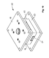
- Fig. 7 to 10 illustrate in more detail the construction of an example of such a multi-piece tool 50, which enables the simultaneous manufacture of four hose closures.
- a base plate 60 On a base plate 60 sits a block 62, in which receptacles 53, cavities 54 and injection channels 56 are located.
- the embodiment of the tool 50 is provided for the production of four Verschlüsssen (two each with inserts 20a, 20b).
- receptacles 53 and bushings 92 for the connecting wires 28a.
- Supply and discharge channels (heating channels) 64 are recessed.
- Blocks and bolts 66 and bores 68 are provided for supporting and guiding plates thereon.
- a fixing block 70 which may be multi-part.
- the tensioning device comprehensive plate 74 having two outer regions 76, 80 of greater height and a central region 78 of lesser height.
- the region 76 covers the block 70.
- the region 78 covers and defines the cavities 54.
- Fig. 10 shows an overall view of the tool 50 with the cover plate 82nd
Landscapes
- Engineering & Computer Science (AREA)
- Mechanical Engineering (AREA)
- Manufacturing & Machinery (AREA)
- Injection Moulding Of Plastics Or The Like (AREA)
- Rigid Pipes And Flexible Pipes (AREA)
- Protection Of Pipes Against Damage, Friction, And Corrosion (AREA)
Abstract
Description
- Die Erfindung betrifft einen Schlauchverschluss, umfassend ein formgebendes Einsatzstück, das in das Schlauchende eingesetzt ist, und einen Elastomerkörper, der das Schlauchende verschließt.
- Schläuche, die beispielsweise als Mantel für elektrische Schaltleisten eingesetzt werden, müssen an den Enden verschlossen werden. Häufig werden zur Abdichtung von Schläuchen Dichtstopfen eingesetzt. Im Fall der elektrischen Schaltleisten müssen elektrische Anschlüsse aus dem Schlauchinneren herausgeführt werden. Hierzu können Dichtstopfen mit einer Bohrung versehen sein. Alternativ werden kappenartige Endstücke auf den Schlauch geschoben und zusammengepresst (gecrimpt) oder festgeklebt. Hierdurch ergibt sich eine Vergrößerung der Schlauchabmessungen. Noch andere Maßnahmen bestehen darin, den Dichtstopfen außen mit Klebstoff zu versehen, so dass er nach dem Einziehen in das Schlauchinnere an der Wandung haftet. Der Hohlraum bis zum Schlauchende wird mit Dichtmasse gefüllt und ein Abschlussstück mit dem Schlauchende verklebt.
- Gemäß der
DE 200 13 310 U1 ist auf das Stirnende eines Kontaktinnenwandungen aufweisenden Schaltleistenschlauchs ein Kontaktierungsbauteil aufschiebbar, das mit einem flexiblen Mantelende ausgestattet ist. Ein formstabiles Plattenelement in Form eines Chipbauteils mit elektrisch leitfähiger Ober-und Unterseite ist mit einem Ende zentral in den Körper des Kontaktierungsbauteils eingesteckt und ist mit dem anderen Ende in den Schaltleistenschlauch eingeschoben. Ein Endwiderstand ist im Kontaktierungsbauteil untergebracht und ist über Anschlussdrähte elektrisch leitend mit dem Plattenelement verbunden. Auf das flexible Mantelende des Kontaktierungsbauteils ist ein Pressring aufgeschoben und zusammengepresst, wodurch eine Flächenpressung zu den Oberflächen des Plattenelements erzielt wird, die eine Fixierung des Kontaktierungsbauteils und elektrische Kontaktierung sicherstellen. Alternativ können am Kontaktierungsbauteil Spitzen oder Dorne vorgesehen sein, die in die elektrisch leitenden Kontaktwandungen eingesteckt werden. Zwischen der Schlauchaußenwandung und der Außenfläche des Kontaktierungsbauteils besteht ein Höhenunterschied, der die Einbaubedingungen mitbestimmt. - Aus der
EP 0 383 671 A1 ist eine elektrische Schaltleiste bekannt, die in einem elektrisch isolierenden Rohrkörper zwei Leiter umfasst, die durch ein oder zwei Stege aus elektrisch isolierendem, weichem, elastischem Material von einander getrennt sind. Es ist ein Anschluss mit zwei Leitern gezeigt, die Zahnungen für eine Verankerung in den Leitern aufweisen. Mittels Schrumpfschlauch wird die Verbindung verschlossen. - In der
DE 196 32 592 C1 ist eine Schaltleiste offenbart, die am Ende einen Konturkörper als Anschlussbauteil aufweist. Von diesem aus erstreckt sich ein nichtleitender Kontaktierungsfortsatz mit leitender Oberfläche und zwei Kontaktdornen, die bis zu den Litzen der elektrischen Leitungen reichen, ins Schlauchinnere. Die Montage des Konturkörpers erfolgt nach starkem Aufweiten des Stirnendes des Schlauchs. Werden die Aufweitmittel entfernt, schließt sich der Schlauch aufgrund seiner Eigenspannung um den Konturkörper und die Kontaktdorne stechen in die Kontaktwandungen des Schlauchs ein. Als weitere Maßnahme ist beschrieben, die Kontaktdorne definiert in die Kontaktwandungen einzudrücken. - Der Erfindung liegt die Aufgabe zugrunde, einen Schlauchverschluss zu schaffen, der für elektrische Schaltleisten verwendbar ist und bei der Herstellung ein einfaches Handhaben erlaubt.
- Diese Aufgabe ist durch die Erfindung bei einem Schlauchverschluss mit den Merkmalen des Anspruchs 1 gelöst. Vorteilhafte Weiterbildungen des erfindungsgemäßen Schlauchverschlusses sind Gegenstand der Unteransprüche.
- Ein Schlauchverschluss gemäß der Erfindung umfasst ein formgebendes Einsatzstück, das in das Schlauchende eingesetzt ist, und einen Elastomerkörper, der das Schlauchende verschließt. Der Schlauch sowie der Elastomerkörper sind aus Kautschuk, vorzugsweise EPDM. Der Elastomerkörper ist an die Stirnseite des Schlauchs anvulkanisiert und setzt diesen in Längsrichtung bündig fort. Das Einsatzstück ragt mit dem freien Ende über das Schlauchende hinaus und ist dort von dem Elastomerkörper umgeben, wobei das Einsatzstück in dem für das Schlauchinnere vorgesehenen Bereich an gegenüberliegenden Seiten-mindestens jeweils einen Stachelvorsprung aufweist, mit dem es in die Schlauchwandung sticht.
- Das Einsatzstück, das sich mit einem Teil im Endbereich des Schlauchs befindet und mit dem anderen Teil vom Elastomerkörper umgeben ist, verleiht dieser Verbindung Stabilität und erleichtert die Anfügung des Elastomerkörpers an das Schlauchende, indem es eine Ausrichtung desselben auf einfache Weise ermöglicht. Die Anvulkanisation des Elastomerkörpers liefert eine durchgehende tangentiale Fortsetzung des Schlauchs ohne Dimensionsänderung (Vergrößerung der Abmessungen), wie sie ansonsten bei Aufstecken und Verpressen oder Aufschrumpfen bzw. Verkleben eines Elastomerteils entsteht. Das heißt, der Übergang von Schlauch und Elastomerkörper ist ohne jegliche Stufe oder Verdickung wie bei einem einzigen Teil. Durch die Stachelvorsprünge ist das Einsatzstück während der Montage und auch später fest gehaltert und das Schlauchende stabil geschlossen. Im Fall eines Schaltleistenschlauchs besteht eine formschlüssige Verbindung zwischen den leitenden Stachelvorsprüngen und den elektrisch leitenden Mantelbereichen des Schlauchs.
- Sind am Einsatzstück Anschlussdrähte vorgesehen, ist für diese durch die stoffschlüssige Verbindung mit dem Elastomermaterial eine Zugentlastung gebildet. Ist am Einsatzstück ein Prüfwiderstand oder ein sonstiges Bauteil angebracht, stellt dieser zusätzlich einen Widerstand gegen Zug in Längsrichtung dar.
- Dadurch, dass das Elastomermaterial und der Schlauchmantel heiß zusammenvulkanisiert werden, ergibt sich eine stoffschlüssige Verbindung, die besonders dicht und fest ist.
- Eine Vorichtung zur Herstellung eines erfindungsgemäßen Schlauchverschlusses ist mit einem Hohlkörper versehen, der eine Aufnahme für das Schlauchende einschließlich des eingesetzten Einsatzstücks und einen Hohlraum für den zu bildenden Elastomerkörper umfasst. Im Hohlraum endet ein Einspritzkanal. Des Weiteren ist eine Spannvorrichtung vorgesehen, die das Schlauchende umschließt und druckbeaufschlagt. Eine Heizeinrichtung ist vorgesehen, die die Spannvorrichtung sowie den Hohlkörper im Bereich des entstehenden Elastomerkörpers erwärmt.
- Bei einer vorteilhaften Ausführung der erfindungsgemäßen Vorrichtung ist die Spannvorrichtung mit dem Hohlkörper integriert.
- Bei einer mehrteiligen, vorzugsweise zweiteiligen Ausführung der Vorrichtung braucht das Schlauchende lediglich in die Aufnahme eingelegt und dann der zweite Teil aufgesetzt werden. Aussparungen für die Kabeldurchführung sind zweckmäßig vorgesehen.
- Die Spannvorrichtung ist vorzugsweise mit einer Profilierung versehen, um den Halteeingriff mit dem Schlauchende zu verstärken. Es kommt hierbei zu einer fixierend wirkenden Verformung des Schlauchmantels, die sich nach der Entnahme des mit dem Verschluss versehenen Schlauchs vollständig elastisch zurückbildet.
- Die Abläufe bei der Herstellung des Schlauchverschlusses unter Verwendung der beschriebenen Vorrichtung sind wie folgt:
- Das Einsatzstück wird in der vorgesehenen Länge in den Schlauch bis zu einer definierten Tiefe eingeschoben. Dieser kann ausreichend elastisch sein, um das Einschieben zu ermöglichen. Andernfalls kann der Mantel auch durch leichten seitlichen Druck aufgeweitet werden. Dadurch wird insbesondere im Fall von Stachelvorsprüngen die erforderliche Höhe freigegeben. Lediglich in Ausnahmefällen wird es erforderlich sein, zuvor das Schlauchende aufzuweiten.
- Dann wird das Schlauchende mit dem teilweise vorstehenden Einsatzstück in eine Spritzform, d.h. die Aufnahme einer Einspritz-Vulkanisier-Vorrichtung, eingebracht. Die Aufnahme hat im inneren Bereich einen Hohlraum für den zu bildenden Elastomerkörper. Dort endet ein Einspritzkanal. Sofern mehrere Schlauchverschlüsse in einem Werkzeug parallel, d.h. gleichzeitig, gefertigt werden, sind entsprechend viele Hohlräume, Einspritzkanäle, etc. vorhanden. Die folgende Beschreibung bezieht sich auf eine Ausführung für die Herstellung eines einzigen Schlauchverschlusses mit entsprechend einem Hohlraum.
- Das Schlauchende wird von der Spritzform umschlossen und dabei von einer Spannvorrichtung gehaltert und druckbeaufschlagt. Der Schlauch wird in der Regel zusammengedrückt, bis seine ursprüngliche Außenkontur wieder oder nahezu wieder erreicht ist. Das Einsatzstück ist dann unverrückbar fixiert. Im Fall von Stachelvorsprüngen werden diese beim Festspannen in den Schlauchmantel gepresst und verankern sich dort. Handelt es sich um den Schlauch einer Schaltleiste, dringen die Stachelvorsprünge in das elektrisch leitende Material ein, wobei eine leitende Verbindung zwischen dem Einsatzstück und dem leitenden Teil des Schlauchmantels hergestellt wird.
- Durch das Pressen des Einsatzstücks über das Schlauchende wird das Einsatzstück während der Herstellung des Schlauchverschlusses zentriert im Hohlraum gehalten.
- Die Aufnahme wird im Bereich des zu bildenden Elastomerkörpers erwärmt. Der Stempel der Vorrichtung, d.h. die Spannvorrichtung, wird mit aufgeheizt, damit das Schlauchende eine genügend hohe Temperatur erreicht. Die Erwärmung ist jedoch nur örtlich und der Schlauch außerhalb des in die Vorrichtung eingebrachten Schlauchteils hat eine wesentlich niedrigere Temperatur als der aufgeheizte Bereich und kann daher auf einfache Weise gehandhabt werden.
- Das Elastomermaterial wird in den Hohlraum eingespritzt und wird an den Stirnkanten des Schlauchs anvulkanisiert. Durch das Einsatzstück ergibt sich eine Stabilisierung des gebildeten Elastomerkörpers. Wenn der Einsatzkörper mit Stachelvorsprüngen versehen ist, verhindern die im Schlauchmantel verankerten Stachelvorsprünge ein Verrutschen des Einsatzstücks ins Schlauchinnere aufgrund des beim Spritzvorgang entstehenden Überdrucks. Beim Pressvorgang dringen die Stachelvorsprünge gewöhnlich nicht bis zu ihrem Fuß in den Schlauchmantel ein. In den so gebildeten Zwischenraum zwischen der Schlauchinnenfläche und dem Einsatzstück fließt während des Einspritzens Elastomermaterial und verbindet den Elastomerkörper dort ebenfalls mit dem Schlauchmantel. Durch die vergrößerte Anspritzfläche zusätzlich zu der Stirnseitenfläche wird der Zusammenhalt verbessert.
- Die Erfindung wird im folgenden weiter anhand eines Ausführungsbeispiels und der Zeichnung beschrieben. Diese Darstellung dient lediglich zur Veranschaulichungszwecken und soll die Erfindung nicht auf die konkret angegebenen Merkmalskombinationen einschränken. Es zeigen
- Fig. 1
- eine Längsschnittansicht einer elektrischen Schaltleiste mit an beiden Enden gemäß der Erfindung ausgestattetem Schlauchverschluss,
- Fig. 2
- und 3 Schnittansichten der Einsatzstücke der beiden Schlauchverschlüsse von
Fig. 1 mit elektrischen Anschlussleitungen und Prüfwiderstand, - Fig. 4
- eine Querschnittansicht eines Schlauchendes mit Einsatzstück vor dem Einspritzen von Elastomermaterial,
- Fig. 5
- und 6 schematische Schnittansichten einer Einspritz-Vulkanisier-Vorrichtung gemäß der Erfindung mit bereits fertiggestellten Schlauchverschlüssen gemäß
Fig. 1 mit Anschlussleitungen bzw. Prüfwiderstand, - Fig. 7
- eine perspektivische Draufsicht des unteren Teils einer Einspritz-Vulkanisier-Vorrichtung mit vier Aufnahmen für vier Schlauchenden,
- Fig. 8
- eine perspektivische Draufsicht des unteren Teils der Einspritz-Vulkanisier-Vorrichtung von
Fig. 7 mit aufgesetztem Fixierblock, - Fig. 9
- eine perspektivische Draufsicht der Einspritz-Vulkanisier-Vorrichtung ähnlich
Fig. 8 mit einer weiteren aufgelegten Platte und - Fig. 10
- eine perspektivische Gesamtansicht der Einspritz-Vulkanisier-Vorrichtung von
Fig. 7 bis 9 . - Im Folgenden werden der Aufbau und die Anordnung eines erfindungsgemäßen Schlauchverschlusses am Beispiel eines Schaltleistenschlauchs anhand von
Fig. 1 bis 3 beschrieben. - Eine elektrische Schaltleiste in dem dargestellten Ausführungsbeispiel hat einen Schlauch 2, der aus mehreren Komponenten aufgebaut ist. Außen umfasst er einen Mantel 4 aus nicht leitendem Material (vorzugsweise EPDM - Ethylen-Propylen-DienKautschuk). An gegenüberliegenden Innenflächen ist der Mantel 4 mit einer Schicht 6 aus leitendem Material (vorzugsweise EPDM) versehen, in die vorzugsweise ein elektrischer Draht 8 einextrudiert ist. Im Übrigen umgrenzt der Schlauch 2 eine Hohlkammer 10. Am Ende ist in den Schlauch 2 jeweils ein formgebendes Einsatzstück 20 (20a, 20b) teilweise eingeschoben, das im Folgenden mehr im Einzelnen beschrieben wird.
- Das gezeigte Einsatzstück 20a, 20b ist plattenförmig. Dies ist je nach Ausführungsbeispiel und Anwendungsfall nicht zwingend. Andere Gestaltungen sind möglich. Der Grundkörper 22a, 22b des Einsatzstücks 20a, 20b ist aus elektrisch nicht leitendem Material. An gegenüber liegenden Flächen - vorliegend oben und unten - ist die Oberfläche des Einsatzstücks 20a, 20b ganz oder teilweise mit einer Schicht 24a, 24b aus leitendem Material versehen. An dem in den Schlauch 2 ragenden Abschnitt des Einsatzstücks 20a, 20b erstrecken sich aus der Schicht 24a, 24b Stachelvorsprünge 26a, 26b in der Form von sich verjüngenden Stacheln (mit konischer oder Pyramidenform) oder Pins fort. Die Stachelvorsprünge 26a, 26b können z.B. auch aufgelötet sein. Pro Fläche ist mindestens ein Vorsprung vorgesehen. Ihre Gestalt könnte auch ein zylindrischer Stift oder ein Steg oder eine Rippe oder ein Körper anderer Gestalt sein, sofern der Körper in einer Spitze, einem Grat oder dergleichen endet. An dem sich außerhalb des Schlauchs 2 befindenden Abschnitt des Einsatzstücks 20a sind oben und unten Anschlussdrähte 28a angelötet und bedarfsweise Aufbauten vorhanden. Der sich außerhalb des Schlauchs 2 befindende Abschnitt des Einsatzstücks 20b ist mit einem Prüfwiderstand 30b oder anderen Aufbauten versehen und die Schichten 24b sind an der Stirnkante 32b miteinander verbunden. Alternativ können die Schichten 24b auch durch ein Loch im Einsatzstück verbunden sein.
- Die Dimensionierung des Einsatzstücks 20 und der Hohlkammer 10 beim dargestellten Ausführungsbeispiel ist derart, dass die Hohlkammer 10 das Einsatzstück 20 beim Einschieben aufnimmt und dieses danach mit der Ober- und Unterseite zwischen den leitenden Schichten 6 mehr oder weniger eng an diesen anliegend ruht, wie in
Fig. 4 gezeigt ist. Die Stacheln 26 (26a, 26b) sind in die leitenden Schichten 6 eingedrückt und stellen einen elektrischen Kontakt mit diesen sicher, wobei sie außerdem das Einsatzstück im Schlauch 2 verankern. - An die Stirnseite des Schlauchs 2 schließt sich jeweils fluchtend ein kappenartiger Elastomerkörper 40 (40a, 40b) aus vorzugsweise EPDM an. Der Elastomerkörper 40 ist durch Anspritzen hergestellt worden und durch Vulkanisation mit dem Schlauch an dessen Stirnfläche verbunden worden, wie durch den Pfeil 42 veranschaulicht ist. Durch den Elastomerkörper 40a erstrecken sich die Anschlussdrähte 28a nach außen. Bei Verwendung von vorzugsweise EPDM-isolierten Anschlussdrähten wird die Isolierung der Anschlussdrähte mit dem Elastomerkörper vulkanisiert. Durch ihre Einbettung in das Elastomermaterial sind sie gegen Zug gesichert und abgedichtet. Der Widerstand 30b, der in den Elastomerkörper 40b eingebettet ist, stellt eine zusätzliche Verankerung des Einsatzstücks 22b dar. Dies ist auch der Fall für zusätzliche Aufbauten auf dem Einsatzstück.
-
Fig. 5 und 6 veranschaulichen den Aufbau einer Einspritz-Vulkanisier-Vorrichtung (Werkzeug) 50 zur Herstellung von Schlauchverschlüssen wie gezeigt. Die Ansichten entsprechen dem Zustand nach der Herstellungsprozedur und vor Entnahme der fertigen Teile. Das Werkzeug 50 umfasst einen Hohlkörper 52 mit einer Aufnahme 53 für das Schlauchende einschließlich Einsatzstück (sieheFig. 7 ) und einem Hohlraum 54 für den zu bildenden Elastomerkörper 40a. In den Hohlraum 54 mündet ein Einspritzkanal 56. Eine Spannvorrichtung 58, von der zwei Stempel gezeigt sind, ist in das Werkzeug 50 integriert und druckbeaufschlagt das Ende des Schlauchs 2. Die Arbeitsflächen der Stempel 58 weisen eine Profilierung 580 zur Verbesserung des Halteeingriffs der Spannvorrichtung 58 auf. Mittels der Profilierung 580 wird eine formgebende Klemmung des Schlauchendes während des Produktionsprozesses ermöglicht. Nach dem Lösen der Spannvorrichtung formt sich der Mantel 4 des Schlauchs an den Klemmstellen wieder zurück. Für die Anschlussdrähte 28a der Einsatzstücke 20a sind Durchführungen 92 und Aussparungen 84, 90 vorgesehen, sieheFig. 7 bis 10 . - Die Arbeitsschritte zur Herstellung eines Schlauchverschlusses gemäß der Erfindung sind wie folgt:
- Einschieben eines Teils des Einsatzstücks in das Schlauchende,
- Einführen des Schlauchendes in einen Hohlkörper einer Einspritz-Vulkanisier-Vorrichtung,
- Pressen des mit dem Einsatzstück versehenen Schlauchendes, vorzugsweise, bis die Schlauchaußenkontur wieder oder nahezu wieder erreicht wird, und vorzugsweise formgebend,
- Erwärmen des Schlauchendes und des Hohlkörpers im Bereich des zu bildenden Elastomerkörpers,
- Einspritzen von Elastomermaterial in den Hohlkörper und
- Anvulkanisation an das Schlauchende.
-
Fig. 7 bis 10 veranschaulichen den Aufbau eines Beispiels eines solchen mehrteiligen Werkzeugs 50 mehr im Einzelnen, das die gleichzeitige Herstellung von vier Schlauchverschlüssen ermöglicht. Auf einer Grundplatte 60 sitzt ein Block 62, in dem sich Aufnahmen 53, Hohlräume 54 und Einspritzkanäle 56 befinden. Das Ausführungsbeispiel des Werkzeugs 50 ist für die Herstellung von vier Verschlüsssen (je zwei mit Einsatzstücken 20a, 20b) vorgesehen. Bei den zwei äußeren Stationen befinden sich Aufnahmen 53 und Durchführungen 92 für die Anschlussdrähte 28a. Zu- und Ableitungskanäle (Heizkanäle) 64 sind ausgespart. Blöcke und Bolzen 66 sowie Bohrungen 68 sind zur Halterung und Führung von darauf liegenden Platten vorgesehen. - Quer über die Aufnahmen 53 erstreckt sich ein Fixierblock 70, der mehrteilig sein kann. Hierauf ist eine die Spannvorrichtung umfassende Platte 74 aufgesetzt, die zwei äußere Bereiche 76, 80 mit größerer Höhe und einen mittleren Bereich 78 mit geringerer Höhe aufweist. Der Bereich 76 überdeckt den Block 70. Der Bereich 78 überdeckt und definiert die Hohlräume 54.
Fig. 10 zeigt eine Gesamtansicht des Werkzeugs 50 mit der Deckplatte 82.
Claims (13)
- Schlauchverschluss, umfassend ein formgebendes Einsatzstück (20), das in das Schlauchende eingesetzt ist, und einen Elastomerkörper (40), der das Schlauchende verschließt,
dadurch gekennzeichnet, dass der Schlauch (2) aus Kautschuk ist,
der Elastomerkörper (40) aus Kautschuk ist, an den Schlauch anvulkanisiert ist und diesen in Längsrichtung bündig fortsetzt und
das Einsatzstück (20) mit dem freien Ende über das Schlauchende hinausragt und dort von dem Elastomerkörper (40) umgeben ist, wobei das Einsatzstück (20) in dem für das Schlauchinnere vorgesehenen Bereich an gegenüberliegenden Seiten mindestens jeweils einen Stachelvorsprung (26) aufweist, mit dem es in die Schlauchwandung sticht. - Schlauchverschluss nach Anspruch 1, dadurch gekennzeichnet, dass das Einsatzstück (20a, 20b) mit Aufbauten (30b) versehen ist.
- Schlauchverschluss nach Anspruch 1 oder 2 für eine elektrische Schaltleiste mit elektrisch leitender Schlauchinnenschicht, dadurch gekennzeichnet, dass das Einsatzstück (20a) aus nicht leitendem Material ist, zwei voneinander elektrisch isolierte Außenflächen (24a) mit jeweils mindestens einem elektrisch leitenden Stachelvorsprung (26a) sowie zwei mit diesem verbundene elektrische Anschlussleitungen (28a) aufweist.
- Schlauchverschluss nach Anspruch 1 oder 2 für eine elektrische Schaltleiste mit elektrisch leitender Schlauchinnenschicht, dadurch gekennzeichnet, dass das Einsatzstück (20b) aus nicht leitendem Material ist, zwei voneinander elektrisch isolierte Außenflächen (24b) mit jeweils mindestens einem elektrisch leitenden Stachelvorsprung (26b) und einen Prüfwiderstand (30b) sowie eine Verbindung der Außenflächen (32b) aufweist.
- Schlauchverschluss nach einem der Ansprüche 1 bis 4, dadurch gekennzeichnet, dass die Stachelvorsprünge (26) sich von dem Einsatzstück (20) aus nach außen verjüngen.
- Schlauchverschluss nach einem der Ansprüche 1 bis 5, dadurch gekennzeichnet, dass die Eingriffsenden der Stachelvorsprünge (26) als Spitzen oder Kanten ausgeführt sind.
- Einspritz-Vulkanisier-Vorrichtung zur Herstellung eines Schlauchverschlusses nach einem der Ansprüche 1 bis 6, dadurch gekennzeichnet, dass
ein Hohlkörper (50) eine Aufnahme für das Schlauchende einschließlich des eingesetzten Einsatzstücks mit einem Hohlraum (54) für den zu bildenden Elastomerkörper (40) umfasst,
ein Einspritzkanal (56) im Hohlraum endet,
eine Spannvorrichtung (58) vorgesehen ist, die das Schlauchende umschließt und druckbeaufschlagt, und
eine Heizeinrichtung vorgesehen ist, die die Spannvorrichtung (58) sowie den Hohlkörper (50) im Bereich des entstehenden Elastomerkörpers (40) erwärmt. - Vorrichtung nach Anspruch 7, dadurch gekennzeichnet, dass die Spannvorrichtung (58) mit dem Hohlkörper (50) integriert ist.
- Vorrichtung nach Anspruch 7 oder 8, dadurch gekennzeichnet, dass die Spannvorrichtung (58) mehrteilig, vorzugsweise zweiteilig, ist.
- Vorrichtung nach einem der Ansprüche 7 bis 9, dadurch gekennzeichnet, dass die Spannvorrichtung (58) mit einer Profilierung (580) versehen ist.
- Vorrichtung nach einem der Ansprüche 7 bis 10, dadurch gekennzeichnet dass eine oder mehrere Aussparungen (84) für die Kabeldurchführung vorgesehen sind.
- Verfahren zur Herstellung des Verschlusses eines Schlauchs mit einem formgebenden Einsatzstück, insbesondere für elektrische Schaltleisten, insbesondere nach einem der Ansprüche 1 bis 6, umfassend die folgenden Schritte:Einschieben eines Teils des Einsatzstücks in das Schlauchende,Einführen des Schlauchendes in einen Hohlkörper einer Einspritz-Vulkanisier-Vorrichtung,Pressen des mit dem Einsatzstück versehenen Schlauchendes,Erwärmen des Schlauchendes und des Hohlkörpers im Bereich des zu bildenden Elastomerkörpers,Einspritzen von Elastomermaterial in den Hohlkörper undAnvulkanisation an das Schlauchende.
- Verfahren nach Anspruch 12, bei dem ein Einsatzstück mit Stachelvorsprüngen verwendet wird, dadurch gekennzeichnet, dass das Schlauchende nach dem Einschieben des Einsatzstücks gepresst wird, bis die Ausgangskontur des Schlauchs erreicht oder nahezu erreicht wird.
Priority Applications (2)
| Application Number | Priority Date | Filing Date | Title |
|---|---|---|---|
| EP19168111.3A EP3582240B1 (de) | 2011-07-13 | 2012-07-11 | Schlauchverschluss |
| PL12005119T PL2546846T3 (pl) | 2011-07-13 | 2012-07-11 | Zamknięcie węża |
Applications Claiming Priority (1)
| Application Number | Priority Date | Filing Date | Title |
|---|---|---|---|
| DE202011050716U DE202011050716U1 (de) | 2011-07-13 | 2011-07-13 | Schlauchverschluss |
Related Child Applications (1)
| Application Number | Title | Priority Date | Filing Date |
|---|---|---|---|
| EP19168111.3A Division EP3582240B1 (de) | 2011-07-13 | 2012-07-11 | Schlauchverschluss |
Publications (2)
| Publication Number | Publication Date |
|---|---|
| EP2546846A1 true EP2546846A1 (de) | 2013-01-16 |
| EP2546846B1 EP2546846B1 (de) | 2019-04-10 |
Family
ID=46551350
Family Applications (2)
| Application Number | Title | Priority Date | Filing Date |
|---|---|---|---|
| EP19168111.3A Active EP3582240B1 (de) | 2011-07-13 | 2012-07-11 | Schlauchverschluss |
| EP12005119.8A Active EP2546846B1 (de) | 2011-07-13 | 2012-07-11 | Schlauchverschluss |
Family Applications Before (1)
| Application Number | Title | Priority Date | Filing Date |
|---|---|---|---|
| EP19168111.3A Active EP3582240B1 (de) | 2011-07-13 | 2012-07-11 | Schlauchverschluss |
Country Status (8)
| Country | Link |
|---|---|
| EP (2) | EP3582240B1 (de) |
| DE (2) | DE202011050716U1 (de) |
| DK (1) | DK2546846T3 (de) |
| ES (1) | ES2733556T3 (de) |
| HU (1) | HUE044382T2 (de) |
| PL (1) | PL2546846T3 (de) |
| PT (1) | PT2546846T (de) |
| TR (1) | TR201905597T4 (de) |
Cited By (2)
| Publication number | Priority date | Publication date | Assignee | Title |
|---|---|---|---|---|
| EP3093115A1 (de) * | 2015-05-13 | 2016-11-16 | Stefan Pfaff Werkzeug- und Formenbau GmbH Co KG | Aufnahmevorrichtung und anspritzverfahren |
| US9605470B2 (en) | 2014-03-18 | 2017-03-28 | Nishikawa Rubber Co., Ltd. | Protector with sensor and method of molding end part of the same |
Citations (7)
| Publication number | Priority date | Publication date | Assignee | Title |
|---|---|---|---|---|
| DE2156396A1 (de) * | 1970-11-13 | 1972-05-18 | Esso Research and Engineering Co , Linden, NJ (VStA) | Verfahren und Vorrichtung zur Her stellung von Hohlkörpern |
| DE2747157A1 (de) * | 1976-06-29 | 1979-04-26 | Mesnel Sa Ets | Verfahren und vorrichtung zur herstellung einer winkelverbindung aus zwei dichtungsteilen |
| EP0383671A1 (de) | 1989-02-13 | 1990-08-22 | Jaeger | Hindernisdetektor mit einem verbesserten Verbindungszusammenbau |
| DE4126594A1 (de) * | 1991-08-12 | 1993-02-18 | Alexandros Taskas | Verfahren zum herstellen von gummielastischen teilen aus einem kautschukartigen material |
| DE19632592C1 (de) | 1996-08-13 | 1998-01-02 | Mayser Gmbh & Co | Schaltleiste mit einem bei einer Krafteinleitung auf seine Außenseite elastisch nachgiebigen Hohlprofil |
| DE20013310U1 (de) | 2000-07-31 | 2000-12-21 | Mayser GmbH & Co, 89073 Ulm | Schaltleiste mit einem Hohlprofil |
| DE102008010074B3 (de) * | 2008-02-19 | 2009-02-19 | Mayser Gmbh & Co. Kg | Schaltleiste |
Family Cites Families (2)
| Publication number | Priority date | Publication date | Assignee | Title |
|---|---|---|---|---|
| WO1994008119A1 (en) * | 1992-09-25 | 1994-04-14 | Rockwell International Corporation | Safety edge switch system |
| DE69408788T2 (de) * | 1993-09-22 | 1998-07-02 | Whitaker Corp | Elektrische Verbindung für zweiadrigen leitende Elastomerleiste |
-
2011
- 2011-07-13 DE DE202011050716U patent/DE202011050716U1/de not_active Expired - Lifetime
-
2012
- 2012-07-11 ES ES12005119T patent/ES2733556T3/es active Active
- 2012-07-11 EP EP19168111.3A patent/EP3582240B1/de active Active
- 2012-07-11 HU HUE12005119 patent/HUE044382T2/hu unknown
- 2012-07-11 PL PL12005119T patent/PL2546846T3/pl unknown
- 2012-07-11 DE DE102012014227A patent/DE102012014227A1/de active Pending
- 2012-07-11 EP EP12005119.8A patent/EP2546846B1/de active Active
- 2012-07-11 TR TR2019/05597T patent/TR201905597T4/tr unknown
- 2012-07-11 DK DK12005119.8T patent/DK2546846T3/da active
- 2012-07-11 PT PT12005119T patent/PT2546846T/pt unknown
Patent Citations (7)
| Publication number | Priority date | Publication date | Assignee | Title |
|---|---|---|---|---|
| DE2156396A1 (de) * | 1970-11-13 | 1972-05-18 | Esso Research and Engineering Co , Linden, NJ (VStA) | Verfahren und Vorrichtung zur Her stellung von Hohlkörpern |
| DE2747157A1 (de) * | 1976-06-29 | 1979-04-26 | Mesnel Sa Ets | Verfahren und vorrichtung zur herstellung einer winkelverbindung aus zwei dichtungsteilen |
| EP0383671A1 (de) | 1989-02-13 | 1990-08-22 | Jaeger | Hindernisdetektor mit einem verbesserten Verbindungszusammenbau |
| DE4126594A1 (de) * | 1991-08-12 | 1993-02-18 | Alexandros Taskas | Verfahren zum herstellen von gummielastischen teilen aus einem kautschukartigen material |
| DE19632592C1 (de) | 1996-08-13 | 1998-01-02 | Mayser Gmbh & Co | Schaltleiste mit einem bei einer Krafteinleitung auf seine Außenseite elastisch nachgiebigen Hohlprofil |
| DE20013310U1 (de) | 2000-07-31 | 2000-12-21 | Mayser GmbH & Co, 89073 Ulm | Schaltleiste mit einem Hohlprofil |
| DE102008010074B3 (de) * | 2008-02-19 | 2009-02-19 | Mayser Gmbh & Co. Kg | Schaltleiste |
Cited By (4)
| Publication number | Priority date | Publication date | Assignee | Title |
|---|---|---|---|---|
| US9605470B2 (en) | 2014-03-18 | 2017-03-28 | Nishikawa Rubber Co., Ltd. | Protector with sensor and method of molding end part of the same |
| EP3093115A1 (de) * | 2015-05-13 | 2016-11-16 | Stefan Pfaff Werkzeug- und Formenbau GmbH Co KG | Aufnahmevorrichtung und anspritzverfahren |
| WO2016180817A1 (de) * | 2015-05-13 | 2016-11-17 | Stefan Pfaff Werkzeug- Und Formenbau Gmbh & Co Kg | Aufnahmevorrichtung und anspitzverfahren |
| US10751921B2 (en) | 2015-05-13 | 2020-08-25 | Stefan Pfaff Werkzeug—Und Formenbau GmbH & Co. KG | Receiving device and injection-molding method |
Also Published As
| Publication number | Publication date |
|---|---|
| EP2546846B1 (de) | 2019-04-10 |
| PT2546846T (pt) | 2019-07-17 |
| DE102012014227A1 (de) | 2013-01-17 |
| ES2733556T3 (es) | 2019-11-29 |
| DE202011050716U1 (de) | 2012-07-27 |
| EP3582240B1 (de) | 2023-02-15 |
| TR201905597T4 (tr) | 2019-05-21 |
| DK2546846T3 (da) | 2019-07-15 |
| PL2546846T3 (pl) | 2019-09-30 |
| HUE044382T2 (hu) | 2019-10-28 |
| EP3582240A1 (de) | 2019-12-18 |
Similar Documents
| Publication | Publication Date | Title |
|---|---|---|
| DE102013101876B3 (de) | Verfahren zum stoffschlüssigen Fügen eines Kabels mit einem Anschlusselement sowie konfiguriertes Kabel | |
| DE102004060186B4 (de) | Verbindungskappe und Kabelverbindungsverfahren, welches dieselbe verwendet | |
| DE102010031771B4 (de) | Verbinderherstellungsverfahren, Formwerkzeug | |
| DE112011102236T5 (de) | Elektrischer Draht mit Anschluss und Verbinder | |
| EP1016168A1 (de) | Elektrische kontakteinrichtung sowie verfahren zur schneidkontaktherstellung | |
| EP2490302A1 (de) | Hochspannungs-Steckverbindungsteil für ein Hochspannungskabel und Verfahren zur Herstellung desselben | |
| EP3695469B1 (de) | Elektrische leitungsanordnung mit direktkontaktierung und verfahren zu deren herstellung | |
| DE102008003848A1 (de) | Kunststoffgehäuse mit integrierter Steckerschnittstelle | |
| DE3912139C2 (de) | Verfahren zum Umspritzen der Verbindungsstelle zweier elektrischer Leitungen | |
| EP2546846B1 (de) | Schlauchverschluss | |
| DE10054714B4 (de) | Verfahren zum Abdichten eines Kabels oder Kabelsatzes an/in einem Kabeldurchführungselement sowie ein Kabeldurchführungselement | |
| DE19539184C3 (de) | Kontaktelement zur Erzeugung eines elektrischen Kontaktes zwischen Hauptleiter und Abzweigleiter sowie Anschlußklemme mit diesem Kontaktelement | |
| DE102008004526A1 (de) | Anschlusseinrichtung | |
| EP2849299A2 (de) | Vorrichtung zur Fixierung eines Kabels und Funktionseinheit | |
| DE10341997A1 (de) | Vorrichtung zum elektrischen Verbinden von mindestens zwei isolierten Hauptleitern eines Energieversorgungskabels, insbesondere Kabelabzweigklemme | |
| DE19845875A1 (de) | Verfahren und mehrpolige Kontaktvorrichtung zum stirnseitigen Kontaktieren von Litzenleitern | |
| DE3806369A1 (de) | Verfahren zur herstellung eines kabelsteckers und giess- oder spritzform zur durchfuehrung des verfahrens | |
| DE102018006083A9 (de) | Abdichteinrichtung und Verfahren zum Abdichten zumindest einer Verbindungsstelle sowie beheizbare Medienleitung mit zumindest einer Abdichteinrichtung | |
| DE19526345C2 (de) | Einrichtung zur elektrischen Verbindung von vorzugsweise zwei elektrischen Leitern | |
| EP3503307A1 (de) | Elektrisches kupplungsteil und dichtelement | |
| EP1473801B1 (de) | Kabelabzweigklemme für Energieversorgungskabel | |
| DE3326386C2 (de) | ||
| EP1283536A2 (de) | Elektrisches Gerät mit einer Wandung aus Kunststoff, umfassend zumindest einen flexiblen Leiter, sowie ein Verfahren zur Herstellung enes solchen elektrischen Gerätes | |
| DE102024136459B3 (de) | Verfahren zur herstellung eines steckverbinders | |
| DE3809209A1 (de) | Isolierkoerper |
Legal Events
| Date | Code | Title | Description |
|---|---|---|---|
| PUAI | Public reference made under article 153(3) epc to a published international application that has entered the european phase |
Free format text: ORIGINAL CODE: 0009012 |
|
| AK | Designated contracting states |
Kind code of ref document: A1 Designated state(s): AL AT BE BG CH CY CZ DE DK EE ES FI FR GB GR HR HU IE IS IT LI LT LU LV MC MK MT NL NO PL PT RO RS SE SI SK SM TR |
|
| AX | Request for extension of the european patent |
Extension state: BA ME |
|
| 17P | Request for examination filed |
Effective date: 20130211 |
|
| STAA | Information on the status of an ep patent application or granted ep patent |
Free format text: STATUS: EXAMINATION IS IN PROGRESS |
|
| 17Q | First examination report despatched |
Effective date: 20170519 |
|
| GRAP | Despatch of communication of intention to grant a patent |
Free format text: ORIGINAL CODE: EPIDOSNIGR1 |
|
| STAA | Information on the status of an ep patent application or granted ep patent |
Free format text: STATUS: GRANT OF PATENT IS INTENDED |
|
| GRAS | Grant fee paid |
Free format text: ORIGINAL CODE: EPIDOSNIGR3 |
|
| GRAA | (expected) grant |
Free format text: ORIGINAL CODE: 0009210 |
|
| STAA | Information on the status of an ep patent application or granted ep patent |
Free format text: STATUS: THE PATENT HAS BEEN GRANTED |
|
| INTG | Intention to grant announced |
Effective date: 20190214 |
|
| AK | Designated contracting states |
Kind code of ref document: B1 Designated state(s): AL AT BE BG CH CY CZ DE DK EE ES FI FR GB GR HR HU IE IS IT LI LT LU LV MC MK MT NL NO PL PT RO RS SE SI SK SM TR |
|
| REG | Reference to a national code |
Ref country code: GB Ref legal event code: FG4D Free format text: NOT ENGLISH |
|
| REG | Reference to a national code |
Ref country code: AT Ref legal event code: REF Ref document number: 1119803 Country of ref document: AT Kind code of ref document: T Effective date: 20190415 Ref country code: CH Ref legal event code: EP |
|
| REG | Reference to a national code |
Ref country code: CH Ref legal event code: NV Representative=s name: RENTSCH PARTNER AG, CH |
|
| REG | Reference to a national code |
Ref country code: IE Ref legal event code: FG4D Free format text: LANGUAGE OF EP DOCUMENT: GERMAN |
|
| REG | Reference to a national code |
Ref country code: DE Ref legal event code: R096 Ref document number: 502012014571 Country of ref document: DE |
|
| REG | Reference to a national code |
Ref country code: NL Ref legal event code: FP |
|
| REG | Reference to a national code |
Ref country code: DK Ref legal event code: T3 Effective date: 20190708 |
|
| REG | Reference to a national code |
Ref country code: PT Ref legal event code: SC4A Ref document number: 2546846 Country of ref document: PT Date of ref document: 20190717 Kind code of ref document: T Free format text: AVAILABILITY OF NATIONAL TRANSLATION Effective date: 20190708 |
|
| REG | Reference to a national code |
Ref country code: SE Ref legal event code: TRGR |
|
| REG | Reference to a national code |
Ref country code: LT Ref legal event code: MG4D |
|
| REG | Reference to a national code |
Ref country code: HU Ref legal event code: AG4A Ref document number: E044382 Country of ref document: HU |
|
| PG25 | Lapsed in a contracting state [announced via postgrant information from national office to epo] |
Ref country code: HR Free format text: LAPSE BECAUSE OF FAILURE TO SUBMIT A TRANSLATION OF THE DESCRIPTION OR TO PAY THE FEE WITHIN THE PRESCRIBED TIME-LIMIT Effective date: 20190410 Ref country code: LT Free format text: LAPSE BECAUSE OF FAILURE TO SUBMIT A TRANSLATION OF THE DESCRIPTION OR TO PAY THE FEE WITHIN THE PRESCRIBED TIME-LIMIT Effective date: 20190410 Ref country code: AL Free format text: LAPSE BECAUSE OF FAILURE TO SUBMIT A TRANSLATION OF THE DESCRIPTION OR TO PAY THE FEE WITHIN THE PRESCRIBED TIME-LIMIT Effective date: 20190410 Ref country code: NO Free format text: LAPSE BECAUSE OF FAILURE TO SUBMIT A TRANSLATION OF THE DESCRIPTION OR TO PAY THE FEE WITHIN THE PRESCRIBED TIME-LIMIT Effective date: 20190710 |
|
| PG25 | Lapsed in a contracting state [announced via postgrant information from national office to epo] |
Ref country code: RS Free format text: LAPSE BECAUSE OF FAILURE TO SUBMIT A TRANSLATION OF THE DESCRIPTION OR TO PAY THE FEE WITHIN THE PRESCRIBED TIME-LIMIT Effective date: 20190410 Ref country code: LV Free format text: LAPSE BECAUSE OF FAILURE TO SUBMIT A TRANSLATION OF THE DESCRIPTION OR TO PAY THE FEE WITHIN THE PRESCRIBED TIME-LIMIT Effective date: 20190410 Ref country code: BG Free format text: LAPSE BECAUSE OF FAILURE TO SUBMIT A TRANSLATION OF THE DESCRIPTION OR TO PAY THE FEE WITHIN THE PRESCRIBED TIME-LIMIT Effective date: 20190710 Ref country code: GR Free format text: LAPSE BECAUSE OF FAILURE TO SUBMIT A TRANSLATION OF THE DESCRIPTION OR TO PAY THE FEE WITHIN THE PRESCRIBED TIME-LIMIT Effective date: 20190711 |
|
| REG | Reference to a national code |
Ref country code: ES Ref legal event code: FG2A Ref document number: 2733556 Country of ref document: ES Kind code of ref document: T3 Effective date: 20191129 |
|
| PG25 | Lapsed in a contracting state [announced via postgrant information from national office to epo] |
Ref country code: IS Free format text: LAPSE BECAUSE OF FAILURE TO SUBMIT A TRANSLATION OF THE DESCRIPTION OR TO PAY THE FEE WITHIN THE PRESCRIBED TIME-LIMIT Effective date: 20190810 |
|
| REG | Reference to a national code |
Ref country code: DE Ref legal event code: R097 Ref document number: 502012014571 Country of ref document: DE |
|
| PG25 | Lapsed in a contracting state [announced via postgrant information from national office to epo] |
Ref country code: SK Free format text: LAPSE BECAUSE OF FAILURE TO SUBMIT A TRANSLATION OF THE DESCRIPTION OR TO PAY THE FEE WITHIN THE PRESCRIBED TIME-LIMIT Effective date: 20190410 Ref country code: EE Free format text: LAPSE BECAUSE OF FAILURE TO SUBMIT A TRANSLATION OF THE DESCRIPTION OR TO PAY THE FEE WITHIN THE PRESCRIBED TIME-LIMIT Effective date: 20190410 Ref country code: RO Free format text: LAPSE BECAUSE OF FAILURE TO SUBMIT A TRANSLATION OF THE DESCRIPTION OR TO PAY THE FEE WITHIN THE PRESCRIBED TIME-LIMIT Effective date: 20190410 |
|
| PLBE | No opposition filed within time limit |
Free format text: ORIGINAL CODE: 0009261 |
|
| STAA | Information on the status of an ep patent application or granted ep patent |
Free format text: STATUS: NO OPPOSITION FILED WITHIN TIME LIMIT |
|
| PG25 | Lapsed in a contracting state [announced via postgrant information from national office to epo] |
Ref country code: MC Free format text: LAPSE BECAUSE OF FAILURE TO SUBMIT A TRANSLATION OF THE DESCRIPTION OR TO PAY THE FEE WITHIN THE PRESCRIBED TIME-LIMIT Effective date: 20190410 Ref country code: SM Free format text: LAPSE BECAUSE OF FAILURE TO SUBMIT A TRANSLATION OF THE DESCRIPTION OR TO PAY THE FEE WITHIN THE PRESCRIBED TIME-LIMIT Effective date: 20190410 |
|
| 26N | No opposition filed |
Effective date: 20200113 |
|
| PG25 | Lapsed in a contracting state [announced via postgrant information from national office to epo] |
Ref country code: LU Free format text: LAPSE BECAUSE OF NON-PAYMENT OF DUE FEES Effective date: 20190711 Ref country code: SI Free format text: LAPSE BECAUSE OF FAILURE TO SUBMIT A TRANSLATION OF THE DESCRIPTION OR TO PAY THE FEE WITHIN THE PRESCRIBED TIME-LIMIT Effective date: 20190410 |
|
| PG25 | Lapsed in a contracting state [announced via postgrant information from national office to epo] |
Ref country code: IE Free format text: LAPSE BECAUSE OF NON-PAYMENT OF DUE FEES Effective date: 20190711 |
|
| PG25 | Lapsed in a contracting state [announced via postgrant information from national office to epo] |
Ref country code: CY Free format text: LAPSE BECAUSE OF FAILURE TO SUBMIT A TRANSLATION OF THE DESCRIPTION OR TO PAY THE FEE WITHIN THE PRESCRIBED TIME-LIMIT Effective date: 20190410 |
|
| PG25 | Lapsed in a contracting state [announced via postgrant information from national office to epo] |
Ref country code: MT Free format text: LAPSE BECAUSE OF FAILURE TO SUBMIT A TRANSLATION OF THE DESCRIPTION OR TO PAY THE FEE WITHIN THE PRESCRIBED TIME-LIMIT Effective date: 20190410 |
|
| PG25 | Lapsed in a contracting state [announced via postgrant information from national office to epo] |
Ref country code: MK Free format text: LAPSE BECAUSE OF FAILURE TO SUBMIT A TRANSLATION OF THE DESCRIPTION OR TO PAY THE FEE WITHIN THE PRESCRIBED TIME-LIMIT Effective date: 20190410 |
|
| PGFP | Annual fee paid to national office [announced via postgrant information from national office to epo] |
Ref country code: PT Payment date: 20250624 Year of fee payment: 14 |
|
| PGFP | Annual fee paid to national office [announced via postgrant information from national office to epo] |
Ref country code: CZ Payment date: 20250627 Year of fee payment: 14 |
|
| PGFP | Annual fee paid to national office [announced via postgrant information from national office to epo] |
Ref country code: NL Payment date: 20250723 Year of fee payment: 14 |
|
| PGFP | Annual fee paid to national office [announced via postgrant information from national office to epo] |
Ref country code: HU Payment date: 20250703 Year of fee payment: 14 |
|
| PGFP | Annual fee paid to national office [announced via postgrant information from national office to epo] |
Ref country code: ES Payment date: 20250819 Year of fee payment: 14 Ref country code: FI Payment date: 20250722 Year of fee payment: 14 |
|
| PGFP | Annual fee paid to national office [announced via postgrant information from national office to epo] |
Ref country code: DK Payment date: 20250723 Year of fee payment: 14 Ref country code: DE Payment date: 20250722 Year of fee payment: 14 |
|
| PGFP | Annual fee paid to national office [announced via postgrant information from national office to epo] |
Ref country code: TR Payment date: 20250704 Year of fee payment: 14 Ref country code: PL Payment date: 20250701 Year of fee payment: 14 Ref country code: IT Payment date: 20250731 Year of fee payment: 14 |
|
| PGFP | Annual fee paid to national office [announced via postgrant information from national office to epo] |
Ref country code: BE Payment date: 20250722 Year of fee payment: 14 Ref country code: GB Payment date: 20250724 Year of fee payment: 14 |
|
| PGFP | Annual fee paid to national office [announced via postgrant information from national office to epo] |
Ref country code: AT Payment date: 20250721 Year of fee payment: 14 Ref country code: FR Payment date: 20250723 Year of fee payment: 14 |
|
| PGFP | Annual fee paid to national office [announced via postgrant information from national office to epo] |
Ref country code: SE Payment date: 20250723 Year of fee payment: 14 Ref country code: CH Payment date: 20250801 Year of fee payment: 14 |