EP2546843B1 - Magnetic element for wireless power transmission and power supply device - Google Patents
Magnetic element for wireless power transmission and power supply device Download PDFInfo
- Publication number
- EP2546843B1 EP2546843B1 EP11753244.0A EP11753244A EP2546843B1 EP 2546843 B1 EP2546843 B1 EP 2546843B1 EP 11753244 A EP11753244 A EP 11753244A EP 2546843 B1 EP2546843 B1 EP 2546843B1
- Authority
- EP
- European Patent Office
- Prior art keywords
- magnetic
- conductor
- section
- magnetic material
- power transmission
- Prior art date
- Legal status (The legal status is an assumption and is not a legal conclusion. Google has not performed a legal analysis and makes no representation as to the accuracy of the status listed.)
- Not-in-force
Links
Images


Classifications
-
- H—ELECTRICITY
- H01—ELECTRIC ELEMENTS
- H01F—MAGNETS; INDUCTANCES; TRANSFORMERS; SELECTION OF MATERIALS FOR THEIR MAGNETIC PROPERTIES
- H01F38/00—Adaptations of transformers or inductances for specific applications or functions
- H01F38/14—Inductive couplings
-
- H—ELECTRICITY
- H02—GENERATION; CONVERSION OR DISTRIBUTION OF ELECTRIC POWER
- H02J—CIRCUIT ARRANGEMENTS OR SYSTEMS FOR SUPPLYING OR DISTRIBUTING ELECTRIC POWER; SYSTEMS FOR STORING ELECTRIC ENERGY
- H02J50/00—Circuit arrangements or systems for wireless supply or distribution of electric power
- H02J50/005—Mechanical details of housing or structure aiming to accommodate the power transfer means, e.g. mechanical integration of coils, antennas or transducers into emitting or receiving devices
-
- H—ELECTRICITY
- H02—GENERATION; CONVERSION OR DISTRIBUTION OF ELECTRIC POWER
- H02J—CIRCUIT ARRANGEMENTS OR SYSTEMS FOR SUPPLYING OR DISTRIBUTING ELECTRIC POWER; SYSTEMS FOR STORING ELECTRIC ENERGY
- H02J50/00—Circuit arrangements or systems for wireless supply or distribution of electric power
- H02J50/70—Circuit arrangements or systems for wireless supply or distribution of electric power involving the reduction of electric, magnetic or electromagnetic leakage fields
-
- H—ELECTRICITY
- H02—GENERATION; CONVERSION OR DISTRIBUTION OF ELECTRIC POWER
- H02J—CIRCUIT ARRANGEMENTS OR SYSTEMS FOR SUPPLYING OR DISTRIBUTING ELECTRIC POWER; SYSTEMS FOR STORING ELECTRIC ENERGY
- H02J50/00—Circuit arrangements or systems for wireless supply or distribution of electric power
- H02J50/10—Circuit arrangements or systems for wireless supply or distribution of electric power using inductive coupling
-
- H—ELECTRICITY
- H02—GENERATION; CONVERSION OR DISTRIBUTION OF ELECTRIC POWER
- H02J—CIRCUIT ARRANGEMENTS OR SYSTEMS FOR SUPPLYING OR DISTRIBUTING ELECTRIC POWER; SYSTEMS FOR STORING ELECTRIC ENERGY
- H02J50/00—Circuit arrangements or systems for wireless supply or distribution of electric power
- H02J50/40—Circuit arrangements or systems for wireless supply or distribution of electric power using two or more transmitting or receiving devices
- H02J50/402—Circuit arrangements or systems for wireless supply or distribution of electric power using two or more transmitting or receiving devices the two or more transmitting or the two or more receiving devices being integrated in the same unit, e.g. power mats with several coils or antennas with several sub-antennas
Definitions
- the present invention relates to a magnetic element for wireless power transmission
- Patent document 1 suggests a structure to realize high transmission efficiency and downsizing, which includes a spiral planer coil buried on one side of a magnetic layer, a magnetic window arranged at the center portion of the planer coil, and the magnetic window at least partially structured by a magnetic material.
- Patent document 1 Japanese Unexamined Patent Publication No. 47700/2004 ( Tokukai 2004-47700 )
- CA 2 692 247 A1 discloses a contactless power transmission apparatus in which a planar coil is laminated with a magnetic layer in order to enhance the power transmission.
- US 5 198 647 A discloses a non-contact IC card based on an electromagnetic induction system using small thin-film coils.
- the coils exhibit shielding walls made from an electrically conductive materials to reduce the magnetic flux leakage influencing adjacent coils.
- the present invention is made in view of the above problem, and it is an object of the present invention to provide a magnetic element for wireless power
- An aspect of the present invention is a magnetic element for wireless power transmission, which generates an induced electromotive force by magnetic coupling according to claim 1.
- the aspect of the present invention may be adapted so that the one or more protruding regions are arranged on both sides of the magnetic element relative to the direction of magnetic coupling.
- the one or more protruding regions arranged on the other side relative to the direction of magnetic coupling exert the same function as the magnetic material provided in the direction of aligning the conductor sections arranged in parallel. Therefore, power feeding and power reception at even higher transmission efficiency is possible.
- the aspect of the present invention may be adapted so that the one or more protruding regions are provided throughout the entire magnetic element in a direction of aligning the conductor sections.
- the protruding regions are provided to the entire magnetic element in the direction of aligning the conductor sections. This enables power feeding and power reception at even higher transmission efficiency.
- the aspect of the present invention may be adapted so that the at least one magnetic material section is formed by a soft magnetism substance.
- the soft magnetism substance may be a metal magnetic substance.
- the metal magnetic substance may be an amorphous magnetic substance.
- the above structure with the protruding regions, enables power feeding and power reception at even higher transmission efficiency.
- Another aspect of the present invention is a magnetic element for wireless power transmission according to claim 12.
- the structure of the magnetic element when compared with a structure without the protruding regions, reduces a magnetic field around the conductor section which is not involved in magnetic coupling, and restrains expansion of the overall magnetic field. As a result, it is possible to raise the magnetic flux density at the time of magnetic coupling.
- the magnetic field generated by the flow of the alternating current in the conductor section interplays with another conductor section arranged, thereby generating an induced current.
- a phenomenon in which this induced current works as a resistance is restrained by the magnetic material section arranged in parallel to the conductor section.
- the resistance caused by the induced current is reduced. This enables power feeding and power reception at high transmission efficiency, whether the magnetic element is used on the magnetically-coupling side or on the magnetically-coupled side.
- the conductor section and the magnetic material section may be combined so that the conductor section and the magnetic material section are at least partially integrated with each other while being electrically insulated.
- the conductor section and the magnetic material section are at least partially integrated by bonding with each other, the positional relation of the conductor section and the magnetic material section and the form of protruding regions are maintained as they are at the initial state, even when the conductor section and the magnetic material section are subjected to an external force as vibration or an impact.
- high transmission efficiency of the initial state is maintained for a long time.
- the conductor section when the conductor section generates heat, the heat of the conductor section is efficiently transferred to the magnetic material section via the portion where these sections are integrated. Therefore, the heat of the conductor section is efficiently released through the magnetic material section. This increases distribution of the electric energy, when compared to a case of separating the conductor section from the magnetic material section.
- the conductor section is kept from excessively heating while increasing the transmission quantity, simply by partially integrating the conductor section with the magnetic material section. Further, handling of the conductor section and the magnetic material section becomes easier by the integration. As a result, the magnetic element is easily stored and mounted to various apparatuses.
- the conductor section may have coating made of an electric insulator, and the magnetic material section is bonded with the coating so as to be integrated with the conductor section. That is, the conductor section may have coating made of an electric insulator and the magnetic material section is bonded with the coating.
- Another aspect of the present invention is a power supply device comprising a plurality of the above-described magnetic elements for wireless power transmission, wherein the magnetic elements for wireless power transmission are arranged so as to be flush with one another.
- a power supply device in the form of sheet, mat, or a plate, whose minimum thickness is the height of the magnetic element for wireless power transmission. Further, by two-dimensionally arranging the magnetic elements for wireless power transmission, it is possible to feed power to a power receiving device at the same conditions in any position within the power supply device.
- a magnetic element 1 for wireless power transmission (hereinafter, simply referred to as magnetic element 1) is structured so as to cause an induced electromotive force by magnetic coupling and is usable for power feeding and power reception.
- Examples of such an element for power feeding include those for use in power supply devices 10 whose transmission power ranges from 0.1 W to 500 W and whose power transmission distance ranges from 1 mm to 10 cm.
- the magnetic element 1 is applicable to a power supply device 10 for a wall-hung apparatus such as a wall-hanging thin television set, a power supply device 10 for a settled-type apparatus such as a personal computer and a mouse, a power supply device 10 for a small medical apparatus such as a pacemaker which is implanted in a human body, or the like.
- the magnetic element 1 may be also applicable to a power supply device 10 whose transmission power and power transmission distance exceed those described above; e.g., a power supply device 10 for a robot or an electric vehicle.
- Examples of the magnetic element 1 for power reception include those used in a wall-hung apparatus such as a wall-hanging thin television set, a settled-type apparatus such as a personal computer or a mouse, a small medical apparatus such as a pacemaker which is implanted in a human body, or the like, which are brought into contact with the power supply device 10. Further, the magnetic element 1 is applicable to a robot or an electric vehicle.
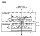
- the magnetic element 1 used as described above is structured so that, in a cross section taken in a direction of magnetic coupling, there are conductor sections 2 and magnetic material sections 3 which are aligned in parallel and adjacent to one another in a direction perpendicular to the direction of magnetic coupling. Further, the magnetic element 1 has protruding regions 61 which are portions of the conductor sections 2 protruding from the magnetic material sections 3 in the direction of magnetic coupling, or portions of the magnetic material sections 3 protruding from the conductor sections 2 in the direction of magnetic coupling.
- the magnetic element 1 has the long conductor sections 2, the long magnetic material sections 3 aligned in parallel and adjacent to the conductor sections 2, and protruding regions 61 which are width directional end portions of the conductor sections 2 extending beyond the width directional end portions of the magnetic material sections 3 or width directional end portions of the magnetic material sections 3 extending beyond the width directional end portions of the conductor sections 2.
- direction of magnetic coupling means a direction of a line connecting the center portions of the magnetic elements 1 on the magnetically-coupling side (power feeding side) and the magnetically-coupled side (power receiving side), when the magnetic elements 1 are arranged face to face so as to achieve a positional relation to cause the strongest magnetic coupling, thus generating the maximum induced electromotive force.
- perpendicular direction means substantially perpendicular.
- the magnetic element 1 structured as described above has the conductor sections 2, the magnetic material sections 3, and the protruding regions 61 which are portions of the conductor sections 2 protruding from the magnetic material sections 3 in the direction of magnetic coupling, or portions of the magnetic material sections 3 protruding from the conductor sections 2 in the direction of magnetic coupling.
- This structure when compared to a structure without the protruding regions 61, reduces a magnetic field around the conductor section 2 which is not involved in magnetic coupling, and restrains expansion of the overall magnetic field. Thus, it is possible to increase the magnetic flux density at the time of magnetic coupling. Further, the magnetic element 1, whether it is on the magnetically-coupling side or on the magnetically-coupled side, achieves a high magnetic flux density. This enables power feeding and power reception with high transmission efficiency.
- the magnetic element 1 is structured so that, in the cross section taken in the direction of magnetic coupling, the plurality of conductor sections 2 are aligned in parallel to each other, and the magnetic material section 3 is provided in at least one gap between a plurality of the conductor sections 2 through which an alternating current flows in the same direction.
- the magnetic element 1 is structured so that the magnetic material section 3 is provided in all the gaps between the conductor sections 2 and that the conductor sections 2 and the magnetic material sections 3 are alternated.
- a structure such that, in the cross section taken in the direction of magnetic coupling, an alternating current flows in the same direction through the plurality of conductor sections 2 is formed by winding the long conductor section 2 and the magnetic material section 3 from the inner to the outer circumferences, or by forming a plurality of conductor sections 2 and a plurality of magnetic material sections 3 in annular shapes sharing a single center point.
- the magnetic field generated by the flow of the alternating current in the conductor section 2 interplays with another conductor section 2 arranged in parallel, thereby generating an induced current.
- a phenomenon in which this induced current works as a resistance is restrained by the magnetic material sections 3 (protruding regions 61) provided in the gaps between conductor sections 2.
- the resistance caused by the induced current is reduced. This enables power feeding and power reception at high transmission efficiency, whether the magnetic element 1 is used on the magnetically-coupling side or on the magnetically-coupled side.
- the magnetic element 1 has a conductor-collected section 6.
- the conductor-collected section 6 has a flat plane shape and has a front surface 6a and a back surface 6b which serve as a magnetism releasing surface to face an apparatus on the power receiving side or on the power feeding side.
- the conductor-collected section 6 may have any given two-dimensional shape.
- the conductor-collected section 6 may have a triangular shape, quadrangular shape, a polygonal shape, an oval or a circular shape.
- the conductor-collected section 6 has the long conductor section 2 and the long magnetic material section 3.
- the conductor section 2 and the magnetic material section 3 are spiraled at equal intervals from the inner circumference side to the outer circumference side.
- the plurality of conductor sections 2 and the plurality of magnetic material sections 3 are arranged in parallel in the direction perpendicular to the direction of magnetic coupling.
- a core section made of a magnetic material may be arranged on the inner circumference side of the conductor-collected section 6. This concentrates the magnetic field to the inner circumference side of the conductor-collected section 6. Further, the magnetic element 1 may have the conductor-collected section 6 exposed to the outside. However, to protect the front surface of the conductor-collected section 6, the front surface 6a and the back surface 6b of the conductor-collected section 6 may have coating made of a protective material made of a non-magnetic and electric insulator; e.g., an insulative resin such as epoxy resin, polyimide resin, glass, or the like.
- the magnetic material section 3 is made of a material having a high magnetic permeability. That is, the magnetic material section 3 may be made of a soft magnetism substance.
- the soft magnetism substance may be a metal magnetic substance.
- the metal magnetic substance may be an amorphous magnetic substance.
- the magnetic material section 3 is formed by compacting magnetic powder with a resin.
- the magnetic powder is for example ferrite, sendust, an amorphous compound, or a magnetic substance having a fine crystal.
- the magnetic material section 3 may be formed by using a strip of ribbon obtained through a rapid solidification processing or the like or a magnetic film formed by conducting a vapor phase epitaxy such as spattering or vapor deposition on an insulative film.
- the amorphous compound may be a Co based amorphous compound, an Fe based amorphous compound.
- the magnetic substance having the fine crystal may be an Fe based magnetic substance having a fine crystal of 300 Angstrom (0.03 ⁇ m).
- the magnetic film formed by vapor phase epitaxy or plating may be a magnetic film based on CoZrNb, CoZrNbTa, FeBN, CoFeB-SiO, CoFeAlO, CoAlPdO, CoFeMn, CoFeN, FeNi, or the like.
- the magnetic material section 3 has a width matching the direction of magnetic coupling and a thickness matching the direction of magnetic coupling (the radial direction of the conductor-collected section 6).
- the conductor section 2 has its ends relative to the length direction connected to a pair of not-shown terminals, respectively.
- each terminal is connected to a power supply unit 8.
- the power supply unit 8 is capable of supplying an alternated power of any given frequency to the conductor section 2.
- each terminal is connected to a rectifier.
- the rectifier smoothens the alternated power formed through electromagnetic induction to a direct-power for use charging a battery, or for use in activating a driving apparatus.
- the magnetic material section 3 when the magnetic material section 3 is made by compacting powder of magnetic substance such as ferrite or amorphous compound by resin; i.e., if the magnetic material section 3 is insulative, the magnetic material section 3 and the conductor section 2 may be brought into contact with each other.
- an insulation layer needs to be disposed between the magnetic material section 3 and the conductor section 2.
- the insulation layer may be, for example, an insulative resin such as polyethylene terephthalate, or an inorganic insulative material such as an oxide.
- the magnetic element 1 has protruding regions 61 which are width directional end portions of the magnetic material sections 3 protruding from the conductor sections 2, or width directional end portions of the conductor sections 2 protruding from the magnetic material sections 3.
- the protruding regions 61 are provided throughout the entire front surface 6a of the conductor-collected section 6. Note that the protruding regions 61 may be provided to one of the front surface 6a and the back surface 6b of the conductor-collected section 6, or may be provided to a part of the front surface 6a and the back surface 6b. In other words, the protruding regions 61 are provided to at least a part of at least one of the front surface 6a and the back surface 6b of the conductor-collected section 6.
- the protruding regions 61 are the width directional end portions of the magnetic material sections 3 projecting from the width directional end portions of the conductor sections 2 so that the front surfaces of the magnetic material sections 3 and the side surfaces of the portions of the magnetic material section 3 protruding from the conductor sections 2 are exposed to outside.
- the protruding regions 61 are preferably such that the exposed surface of each magnetic material section 3 is increased.
- the magnetic material section 3 made of a highly magnetic-permeable material is easily affected by the magnetic field. This prevents a decrease in the occurrence efficiency of a magnetic field, which is attributed to the induced current generated by the magnetic field interplaying between adj acent conductor sections 2 , as shown in FIG. 4 .
- the protruding regions 61 may be width directional end portions of the conductor section 2 protruding from the width directional end portions of the magnetic material section 3.
- the magnetic material section 3 between adjacent conductor sections 2 prevents a decrease in the occurrence efficiency of a magnetic field which is attributed to the induced current generated between the conductor sections 2.
- the protrusion length of the magnetic material sections 3 or the conductor section 2 is preferably such that Dm/d is 0.2 to 3.0. This is because too short a protrusion length causes difficulty in bringing about the effect of preventing a decrease in the occurrence efficiency of the magnetic field while too long a protrusion length causes mechanical problems such as interference of the protruding portions with each other.
- the magnetic elements 1 are two-dimensionally arranged at an even distribution density as in a case of a matrix. This achieves a function of supplying power at evenly high transmission efficiency, throughout the entire power supply device 10. Further, the power supply device 10 may have a plurality of placement regions each having a different distribution density of the magnetic elements 1 from the other regions. In this case, it is possible to adjust the power feeding amount based on the position of the apparatus 9. For example, when the apparatus 9 is a light emitting apparatus having a dimmer control function, the amount of light emitted can be adjusted by changing the position of the apparatus.
- each of the magnetic elements 1 is set so that the front surface 6a to serve as a magnetically releasing surface (magnetism releasing surface) matches with the top surface (placement surface) of the power supply device 10.
- the magnetism releasing surface means the surface of the power feeding side or the power receiving side, and is at least one of the front surface 6a and the back surface 6b of the magnetic element 1.
- the power supply device 10 includes: a placement layer 101 which directly contacts the apparatus 9 and which fixes and holds the conductor section 2 and the magnetic material section 3 ; a support layer 103 having the magnetic element 1; a shielding layer 104 provided on the lower surface of the support layer 103; and a protection layer 105 provided on the lower surface of the shielding layer 104.
- the placement layer 101, the support layer 103, and the protection layer 105 are made of a non-magnetic synthetic resin or the like.
- the shielding layer 104 is made of at least one of a conductive material and a magnetic substance, and is structured to prevent leakage of a magnetic field from the lower side (back surface side) of the power supply device 10.
- the support layer 103 has a not-shown power circuit substrate in the form of sheet. The power circuit substrate enables supplying of a high frequency alternated power from the power supply unit 8 to the magnetic element 1.
- each magnetic element 1 when the power supply device 10 having therein the magnetic elements 1 is connected to the power supply unit 8, and a high frequency alternating current (alternated power) is supplied to the device 10, each magnetic element 1 generates an alternating magnetic field.
- each magnetic element 1 is structured so that, in the cross section taken in the direction of magnetic coupling, the magnetic material section 3 is provided at least one gap between the conductor sections 2 through which the alternating current flows in the same direction, and that each of the conductor sections 2 has a protruding region 61 protruding from the magnetic material section 3 in the direction of magnetic coupling or the magnetic material section 3 has a protruding region 61 protruding from the conductor sections 2 in the direction of magnetic coupling.
- the magnetic element 1 when compared with the structure without the protruding regions 61, reduces a magnetic field around the conductor section 2 which is not involved in magnetic coupling, and restrains expansion of the overall magnetic field.
- This structure of the magnetic element 1 increases the density of magnetic flux towards the apparatus 9 placed on the power supply device 10.
- the power supply device 10 with many magnetic elements 1 is capable of feeding power to the apparatus 9 at high transmission efficiency.
- the magnetic field generated by the flow of the alternating current in the conductor section 2 interplays with another adjacent conductor section 2, thereby generating an induced current.
- a phenomenon in which this induced current works as a resistance is restrained by the magnetic material sections 3 (protruding regions 61) provided in gaps between conductor sections 2.
- the resistance caused by the induced current is reduced. This enables power feeding at high transmission efficiency.
- the power supply device 10 having these magnetic elements 1 When the magnetic field is released from the front surfaces 6a serving as the magnetism releasing surfaces of all the magnetic elements 1 as described above, the power supply device 10 having these magnetic elements 1 outputs from its entire surface an alternating magnetic field of a frequency corresponding to the frequency of the alternated power. Accordingly, when the apparatus 9 which activates with an induced electromotive force is placed on the power supply device 10, the coil built in the apparatus 9 is magnetically coupled and interplays with the alternating magnetic field to generate an induced electromotive force, as shown in FIG. 2 . The alternated power is then rectified and supplied to the control chip or the like. Note the apparatus 9 may include the magnetic element 1 for power reception, in which case power feeding at even a higher efficiency is possible.
- the present embodiment deals with a case where the magnetic element 1 is structured so that the protruding regions 61 are on the front surface 6a of the conductor-collected section 6, as shown in FIG. 1 and FIG. 3 ; however, the present invention is not limited to this structure.
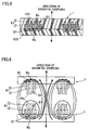
- the magnetic element 1 may have the protruding regions 61 arranged on the front surface 6a and the back surface 6b as shown in FIG. 5 .
- This structure of the magnetic element 1 increases the density of magnetic flux in the direction of magnetic coupling, as shown in FIG. 6 .
- the magnetic element 1 may have the protruding regions 61 arranged only on the back surface 6b which is opposite to the magnetism releasing surface. This structure of the magnetic element 1 also increases the density of magnetic flux in the direction of magnetic coupling, as shown in FIG. 8 .
- the magnetic element 1 may have the protruding regions 61 arranged only on the inner circumference side of the conductor-collected section 6. Alternatively, the magnetic element 1 may have the protruding regions 61 on the outer circumference side of the conductor-collected section 6. Further, in the magnetic element 1, the protrusion length of the protruding regions 61 may be reduced from the inner circumference side to the outer circumference side of the conductor-collected section 6 so that the area of protrusion of the magnetic material section 3 on the inner circumference side is the largest. Further, the conductor sections 2 may have therebetween a plurality of magnetic material sections 3 spaced from each other. Alternatively, the magnetic material sections 3 may have therebetween a plurality of conductor sections 2 spaced from each other. Note that the magnetic element 1 may have a structure which is a combination of the above mentioned structures.
- a magnetic element 201 for wireless power transmission (hereinafter, simply referred to as magnetic element 201) of the present embodiment includes a roll 206 having a lamination 204 which includes a conductor layer 202 through which an alternating current flows; and a magnetic material layer 203 arranged parallel to the length of the conductor layer 202.
- the magnetic material layer 203 has width directional end portions protruding from the width directional end portions of the conductor layer 202, thus forming protruding regions 261.
- the protruding regions 261 may be width directional end portions of the magnetic material layer 203 projecting from the width directional end portions of the conductor layer 202, or the width directional end portions of the conductor layer 202 projecting from the width directional end portions of the magnetic material layer 203.
- the magnetic element 201 has a roll 206.
- the roll 206 has a cylindrical outline, a side circumferential surface 206a, and end surfaces 206b on both ends of the side circumferential surface 206a.
- the end surfaces 206b each forms a magnetism releasing surface.
- the roll 206 may have any given outline.
- the roll 206 may be formed in the form of prism whose end surfaces 206b have a triangular shape, a quadrangular shape, or the like.
- the roll 206 is formed by winding several times the ribbon-like lamination 204. This way, in the vertical section of the roll 206 taken in the axial direction (cross section taken along the line A-A'), a plurality of lamination 204 are aligned in parallel to one another in a radial direction.
- the lamination 204 is wound on the outer circumference of a cylindrical core member 207.
- the core member 207 may be a non-magnetic material or a magnetic material. However, the magnetic material is preferred, because the magnetic field is concentrated at the inner circumference side of the roll 206 wound around the core member 207. Note that the lamination 204 may be wound in a tubular manner, without the core member 207. Further, the shape of winding may be circular, oval, rectangular or any other given shape.
- the lamination 204 has the conductor layer 202 and the magnetic material layer 203.
- the conductor layer 202 and the magnetic material layer 203 are parallel to each other.
- the lamination 204 includes: a magnetic sheet 41 having protection sheets 411 and 412 each made of Polyethylene Terephthalate (PET), which sandwich therebetween a magnetic material layer 203; and a conductive sheet 43 having a substrate 431 made of polyimide (PI) and a conductor layer 202 formed on the substrate 431.
- PET Polyethylene Terephthalate
- PI polyimide
- the magnetic element 201 may have the roll 206 exposed to the outside. However, to protect the front surface of the roll 206, the side circumferential surface 206a and the end surfaces 206b of the roll 206 may have coating of a protective material made of a non-magnetic and electric insulator; e.g., an insulative resin such as epoxy resin, polyimide resin; glass; or the like. Further, to prevent interference of the adjacent magnetic material layers 203 with each other and to prevent deformation of the magnetic material layers 203 adjacent relative to the radial direction, the magnetic element 201 may have a protective material filled in between the magnetic material layers 203.
- a protective material made of a non-magnetic and electric insulator
- the magnetic layer of less than 0.1 ⁇ m in thickness could be too thin to achieve sufficient magnetic property. Further, manufacturing such a thin magnetic layer will require complicated controls. Therefore, the lower limit value of the thickness is preferably 0.1 ⁇ m.
- a preferable material is an amorphous compound which enables manufacturing ribbon through rapid solidification processing. In particular, a preferable magnetic property is achieved with a Co based amorphous compound.
- the conductor layer 202 is made of the same material as the conductor section 2 of the first embodiment.
- the conductor layer 202 is preferably made of a metal material such as Cu, Al, or the like.
- the conductor layer 202 may be a thin film formed through a vapor phase epitaxy, plating, or the like, instead of forming the same in the form of ribbon.
- the magnetic element 201 has protruding regions 261.
- the protruding regions 261 are provided throughout the entire end surfaces 206b on both sides of the roll 206. Note that the protruding regions 261 may be provided to the end surface 206b of one side of the roll 206, or a part of the end surface 206b. In other words, the protruding regions 261 are provided to at least a part of at least one end surface 206b of the roll 206.
- the magnetic element 201 structured as described above is provided to a power supply device 210 as shown in FIG. 9 .
- the power supply device 210 is formed as a sheet or a plate so that one or more apparatuses 9 such as a mobile phone or a personal computer which activates with contactless power feeding is/are placeable. Throughout the entire surface of the power supply device 210 are buried many magnetic elements 201.
- the magnetic element 201 is arranged so that one of its end surfaces 206b, which serves as a magnetically releasing surface (magnetism releasing surface), is the top surface.
- the shielding layer 104 is made of at least one of a conductive material and a magnetic substance, and is structured to prevent leakage of a magnetic field from the lower side of the power supply device 210.
- a not-shown circuit board in the form of a sheet, which is connected to the inner circumference side and the outer circumference side of the conductor layer 202 of the magnetic element 201. The circuit board enables supplying of high frequency alternated power from the power supply unit 8 to the magnetic element 201.
- the electrically insulated state can be achieved by providing an insulator between the conductor section 2 (conductor layer 202) and the magnetic material section 3 (magnetic material layer 203).
- an insulator coating made of an insulative material is formed at least one of the conductor section 2 (conductor layer 202) and the magnetic material section 3 (magnetic material layer 203), through vapor deposition or plating, or an insulative sheet is interposed between the conductor section 2 (conductor layer 202) and the magnetic material section 3 (magnetic material layer 203).
- the insulator and the magnetic material section 3 (magnetic material layer 203) have a higher thermal conductivity than the airspace.
- the conductor section 2 (conductor layer 202) and the magnetic material section 3 (magnetic material layer 203) are at least partially integrated, the positional relation of the conductor section 2 (conductor layer 202) and the magnetic material section 3 (magnetic material layer 203) and the form of protruding regions 61 (261) are maintained as they are at the initial state, even when the conductor section 2 (conductor layer 202) and the magnetic material section 3 (magnetic material layer 203) are subjected to an external force such as vibration or an impact.
- an external force such as vibration or an impact.
- the conductor section 2 (conductor layer 202) generates heat
- the heat of the conductor section 2 (conductor layer 202) is efficiently transferred to the magnetic material section 3 (magnetic material layer 203) via the portion where these sections are integrated. Therefore, the heat of the conductor section 2 (conductor layer 202) is efficiently released through the magnetic material section 3 (magnetic material layer 203). This increases distribution of the electric energy, when compared to a case of separating the conductor section 2 (conductor layer 202) from the magnetic material section 3 (magnetic material layer 203).
- the conductor section 2 may have coating made of an electric insulator, and the magnetic material section 3 (magnetic material layer 203) may be bonded with the coating so as to be integrated with the conductor section 2 (conductor layer 202). That is, the conductor section 2 (conductor layer 202) may have coating made of an electric insulator and the magnetic material section 3 (magnetic material layer 203) may be bonded with the coating.
- a typical coil or the like having insulation coating may be adopted for the conductor section 2 (conductor layer 202). Therefore, the magnetic element 1 (201) is easily obtained. Further, it is possible to obtain an effect similar to that obtained from the rolled coil having a wound shape explained in the above embodiment.
- examples 1 to 3 below a transmission status of a magnetic element 201 having the protruding regions 261 was measured.
- comparative examples 1 and 2 below a transmission status of a magnetic element without the protruding regions 261 was measured.
- the magnetic sheet 41 was cut out in a size of 7 mm (W) x 300 mm (L).
- the conductive sheet 43 was cut out in a size of 5 mm (W) x 300 mm (L).
- One end of the magnetic sheet 41 and one end of the conductive sheet 43 were aligned so that the other end of the magnetic sheet 41 protrudes from the other end of the conductive sheet 43 by 2 mm.
- the both sheets 41 and 43 were bonded by an adhesive layer of 20 ⁇ m, thus preparing a lamination 204.
- An adhesive was applied on the substrate 431 side of the lamination 204 to form an adhesive layer 42 of 20 ⁇ m.
- the lamination 204 was then wound 6.5 times about a cork-made core member 207 of 13 mm ⁇ in diameter.
- a roll 206 having protruding regions 261 on one side was formed. Then one end of a signal line was connected to an end portion on the inner circumference sides of the conductor layer 202 of the roll 206 and one end of another signal line was connected to the outer circumference side of the conductor layer 202 of the roll 206.
- Two rolls 206 were prepared as described above and were arranged symmetrically on the right and left so that the respective sides of the rolls 206 on which the magnetic sheets 41 protruded by 2 mm faced each other. In other words, the rolls 206 were arranged so that the protruding regions 261 of the rolls 206 faced each other. At this time, the conductor layers 202 facing each other were spaced 5 mm away from each other. Further, the rolls 206 were held so that the core of the rolls 206 were concentric.
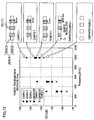
- the other ends of the signal lines having the one ends connected to the rolls 206 were connected to a terminal 1 and a terminal 2 of Network Analyzer (Agilent Technologies Inc.), respectively, and the insertion loss of S parameter (S21) was measured at measurement frequency of 300 kHz, 500 kHz, and 1000 kHz.
- S21 means signals passing through the terminal 2, when signals are input to the terminal 1. S21 is expressed in decibel and the greater the value, the higher the transmission efficiency.
- Two rolls 206 were prepared as described in the example 1 and were symmetrically arranged on the left and right so that the sides of the rolls 206 on which the edges of the magnetic sheet 41 and the conductive sheet 43 were aligned faced each other. In other words, the rolls 206 were arranged so that the protruding regions 261 of the rolls 206 did not face each other. At this time, the conductor layers 202 facing each other were spaced 5 mm away from each other. Then, under the same conditions as the example 1, the insertion loss of S parameter (S21) was measured at measurement frequencies of 300 kHz, 500 kHz, and 1000 kHz.
- a magnetic sheet 41 prepared as described in the example 1 was cut out in a size of 9 mm (W) x 300 mm (L). Further, a conductive sheet 43 same as that of example 1 was cut out in a size of 5 mm (W) x 300 mm (L). Then, a lamination 204 was prepared by aligning the middle portions of the magnetic sheet 41 and the conductive sheet 43 so that the both ends of the magnetic sheet 41 protruded from the copper foil by 2 mm. The lamination 204 was then wound 6.5 times about a cork-made core member 207 of 13 mm ⁇ in diameter. Thus, a roll 206 having protruding regions 261 on both sides was formed.
- Two rolls 206 were prepared as described above and were symmetrically arranged on the left and right so that one side of each roll 206 faced each other. At this time, the conductor layers 202 facing each other were spaced 5 mm away from each other. Then, under the same conditions as the example 1, the insertion loss of S parameter (S21) was measured at measurement frequencies of 300 kHz, 500 kHz, and 1000 kHz.
- a magnetic element 100 having no protruding region 261 was prepared. That is, a magnetic sheet 41 and a conductive sheet 43 were prepared as described in example 1 and were cut out in a size of 5 mm (W) x 300 mm (L). Then, a lamination 204 was formed by laminating the magnetic sheet 41 and the conductive sheet 43 so that the both end surfaces of these sheets were aligned. The lamination 204 was then wound about a cork-made core member 207 of 13 mm ⁇ in diameter, thus forming a roll 206. Two rolls 206 were formed this way and were symmetrically arranged on the left and right so that one side of each roll 206 faced each other.
- the conductor layers 202 facing each other were spaced 5 mm away from each other. Then, under the same conditions as the example 1, the insertion loss of S parameter (S21) was measured at measurement frequencies of 300 kHz, 500 kHz, and 1000 kHz.
- a magnetic element 100 having no magnetic material layer 203 was prepared. That is, instead of the magnetic sheet 41 of example 1, there was formed a lamination 204 having a protection sheet 411 having the same thickness as the magnetic sheet 41. The lamination 204 was then wound about a cork-made core member 207 of 13 mm ⁇ in diameter, thus forming a roll 206. Two rolls 206 were formed this way and were symmetrically arranged on the left and right so that one side of each roll 206 faced each other. At this time, the rolls 206 were spaced 5 mm away from each other. Then, under the same conditions as the example 1, the insertion loss of S parameter (S21) was measured at measurement frequencies of 300 kHz, 500 kHz, and 1000 kHz.
- S21 insertion loss of S parameter
- the examples 1 to 3 having the protruding regions 261 are found to result in higher transmission efficiencies than those resulting from the comparative example 1 having no protruding regions 261 and the comparative example 2 having no magnetic material layer 203. Based on this, the transmission efficiency of the magnetic element 201 is found to be increased with the protruding regions 261, which are the portions of the magnetic material layer 203 protruding from the conductor layer 202.
- the rolls 206 of example 3 having the protruding regions 261 on both sides are found to achieve higher transmission efficiencies than the rolls 206 of examples 1 and 2 having the protruding regions 261 on one side.
- the example 2 in which the protruding regions 261 of the rolls 206 do not face each other is found to achieve higher transmission efficiencies than example 1 in which protruding regions 261 of the rolls 206 face each other. From the above findings, there are clarified that, to improve the transmission efficiency, it is important to arrange protruding regions 261 on both sides having the magnetism releasing surface, and that the transmission efficiency can be improved even without the protruding regions 261 on the side of the magnetism releasing surface.
Applications Claiming Priority (2)
| Application Number | Priority Date | Filing Date | Title |
|---|---|---|---|
| JP2010052049 | 2010-03-09 | ||
| PCT/JP2011/054770 WO2011111585A1 (ja) | 2010-03-09 | 2011-03-02 | 無線電力伝送用磁気素子及び電力供給装置 |
Publications (3)
| Publication Number | Publication Date |
|---|---|
| EP2546843A1 EP2546843A1 (en) | 2013-01-16 |
| EP2546843A4 EP2546843A4 (en) | 2014-06-11 |
| EP2546843B1 true EP2546843B1 (en) | 2016-01-20 |
Family
ID=44563389
Family Applications (1)
| Application Number | Title | Priority Date | Filing Date |
|---|---|---|---|
| EP11753244.0A Not-in-force EP2546843B1 (en) | 2010-03-09 | 2011-03-02 | Magnetic element for wireless power transmission and power supply device |
Country Status (7)
| Country | Link |
|---|---|
| US (1) | US9390849B2 (zh) |
| EP (1) | EP2546843B1 (zh) |
| JP (1) | JP5364745B2 (zh) |
| KR (1) | KR20130014546A (zh) |
| CN (1) | CN102792401B (zh) |
| DK (1) | DK2546843T3 (zh) |
| WO (1) | WO2011111585A1 (zh) |
Families Citing this family (20)
| Publication number | Priority date | Publication date | Assignee | Title |
|---|---|---|---|---|
| JP2012204440A (ja) | 2011-03-24 | 2012-10-22 | Nitto Denko Corp | 無線電力伝送用磁気素子及びその製造方法 |
| EP2730005B1 (en) * | 2011-07-08 | 2021-05-05 | Auckland UniServices Limited | Interoperability of magnetic structures for inductive power transfer systems |
| JP5923916B2 (ja) * | 2011-10-03 | 2016-05-25 | 日産自動車株式会社 | 非接触給電装置 |
| JP5965148B2 (ja) * | 2012-01-05 | 2016-08-03 | 日東電工株式会社 | 無線電力伝送を用いたモバイル端末用受電モジュール及び当該モバイル端末用受電モジュールを備えたモバイル端末用充電池 |
| JP5184705B1 (ja) | 2012-01-05 | 2013-04-17 | 日東電工株式会社 | 無線給電式発光素子、及び発光装置 |
| JP5918020B2 (ja) * | 2012-05-21 | 2016-05-18 | 株式会社神戸製鋼所 | 非接触給電用コイル |
| JP2015015452A (ja) * | 2013-06-06 | 2015-01-22 | Tdk株式会社 | ワイヤレス電力伝送用コイル装置 |
| JP6253998B2 (ja) * | 2013-10-23 | 2017-12-27 | 東芝テック株式会社 | チェックアウト端末 |
| US9123466B2 (en) * | 2013-11-11 | 2015-09-01 | Eaton Corporation | Wireless power transfer systems containing foil-type transmitter and receiver coils |
| KR101762778B1 (ko) | 2014-03-04 | 2017-07-28 | 엘지이노텍 주식회사 | 무선 충전 및 통신 기판 그리고 무선 충전 및 통신 장치 |
| WO2015161053A1 (en) * | 2014-04-16 | 2015-10-22 | Witricity Corporation | Wireless energy transfer for mobile device applications |
| WO2015161035A1 (en) * | 2014-04-17 | 2015-10-22 | Witricity Corporation | Wireless power transfer systems with shield openings |
| JP6365109B2 (ja) * | 2014-08-20 | 2018-08-01 | Tdk株式会社 | コイルユニット |
| JP6365108B2 (ja) * | 2014-08-20 | 2018-08-01 | Tdk株式会社 | コイルユニット |
| JP6365110B2 (ja) * | 2014-08-20 | 2018-08-01 | Tdk株式会社 | コイルユニット |
| CN104682576B (zh) * | 2015-03-01 | 2017-08-29 | 华南理工大学 | 添加自适应双端阻抗变换网络的谐振式无线电能传输系统 |
| US10847299B2 (en) * | 2015-10-26 | 2020-11-24 | Quanten Technologies Limited | Magnetic structures with self-enclosed magnetic paths |
| KR20170058704A (ko) * | 2015-11-19 | 2017-05-29 | 삼성전자주식회사 | 전자 장치 및 그의 액세서리 장치 |
| DE102016103042A1 (de) * | 2016-02-22 | 2017-08-24 | Ipt Technology Gmbh | Spuleneinheit einer Vorrichtung zur induktiven Übertragung elektrischer Energie |
| JP7131815B2 (ja) * | 2018-09-14 | 2022-09-06 | 国立大学法人信州大学 | ワイヤレス電力伝送コイルユニット |
Family Cites Families (19)
| Publication number | Priority date | Publication date | Assignee | Title |
|---|---|---|---|---|
| JPS6120724Y2 (zh) * | 1980-12-05 | 1986-06-21 | ||
| US5062197A (en) * | 1988-12-27 | 1991-11-05 | General Electric Company | Dual-permeability core structure for use in high-frequency magnetic components |
| US5198647A (en) * | 1989-11-28 | 1993-03-30 | Mitsubishi Denki Kabushiki Kaisha | Plural-coil non-contact ic card having pot cores and shielding walls |
| JPH0390371U (zh) * | 1989-12-28 | 1991-09-13 | ||
| JPH0982553A (ja) * | 1995-09-12 | 1997-03-28 | Sanyo Electric Co Ltd | コイルの巻回方法及びコイル |
| JPH11176677A (ja) | 1997-12-09 | 1999-07-02 | Tokin Corp | コードレスパワーステーション |
| JP2000150238A (ja) * | 1998-11-13 | 2000-05-30 | Alps Electric Co Ltd | 平面型磁気素子及び平面型磁気素子の製造方法 |
| JP2000200725A (ja) * | 1998-12-29 | 2000-07-18 | Tokin Corp | 非接触電力伝送装置 |
| JP2003173921A (ja) * | 2001-12-07 | 2003-06-20 | Kawasaki Steel Corp | 非接触充電器用の平面磁気素子 |
| JP2004047700A (ja) | 2002-07-11 | 2004-02-12 | Jfe Steel Kk | 非接触充電器用平面磁気素子 |
| JP4706036B2 (ja) | 2005-02-03 | 2011-06-22 | 学校法人東京理科大学 | 非接触電力供給システム及びそれを用いた医療システム |
| JP2007081239A (ja) | 2005-09-15 | 2007-03-29 | Toshiba Corp | 磁気デバイスおよびそれを用いたスイッチング電源 |
| JP4960710B2 (ja) * | 2007-01-09 | 2012-06-27 | ソニーモバイルコミュニケーションズ株式会社 | 無接点電力伝送コイル、携帯端末及び端末充電装置、平面コイルの磁性体層形成装置及び磁性体層形成方法 |
| JP2008294385A (ja) * | 2007-04-24 | 2008-12-04 | Panasonic Electric Works Co Ltd | 非接触電力伝送機器及びその受電用コイルブロックの製造方法 |
| JP5118394B2 (ja) | 2007-06-20 | 2013-01-16 | パナソニック株式会社 | 非接触電力伝送機器 |
| CN101848891A (zh) | 2007-08-07 | 2010-09-29 | 爱莫里大学 | 通过π-烯丙基过渡金属络合体形成制备合成核苷 |
| JP2009158598A (ja) | 2007-12-25 | 2009-07-16 | Panasonic Electric Works Co Ltd | 平面コイル及びこれを用いた非接触電力伝送機器 |
| JP2010041906A (ja) * | 2008-07-10 | 2010-02-18 | Nec Tokin Corp | 非接触電力伝送装置、軟磁性体シート及びそれを用いたモジュール |
| JPWO2011030539A1 (ja) * | 2009-09-11 | 2013-02-04 | パナソニック株式会社 | 電磁誘導コイルユニットおよび電磁誘導装置 |
-
2011
- 2011-03-02 CN CN201180013298.4A patent/CN102792401B/zh not_active Expired - Fee Related
- 2011-03-02 JP JP2011045231A patent/JP5364745B2/ja not_active Expired - Fee Related
- 2011-03-02 WO PCT/JP2011/054770 patent/WO2011111585A1/ja active Application Filing
- 2011-03-02 DK DK11753244.0T patent/DK2546843T3/en active
- 2011-03-02 KR KR1020127026202A patent/KR20130014546A/ko not_active Application Discontinuation
- 2011-03-02 EP EP11753244.0A patent/EP2546843B1/en not_active Not-in-force
- 2011-03-02 US US13/583,525 patent/US9390849B2/en not_active Expired - Fee Related
Also Published As
| Publication number | Publication date |
|---|---|
| WO2011111585A1 (ja) | 2011-09-15 |
| EP2546843A1 (en) | 2013-01-16 |
| CN102792401A (zh) | 2012-11-21 |
| DK2546843T3 (en) | 2016-03-21 |
| US9390849B2 (en) | 2016-07-12 |
| EP2546843A4 (en) | 2014-06-11 |
| JP5364745B2 (ja) | 2013-12-11 |
| US20130002041A1 (en) | 2013-01-03 |
| JP2011211176A (ja) | 2011-10-20 |
| KR20130014546A (ko) | 2013-02-07 |
| CN102792401B (zh) | 2016-06-29 |
Similar Documents
| Publication | Publication Date | Title |
|---|---|---|
| EP2546843B1 (en) | Magnetic element for wireless power transmission and power supply device | |
| KR101707883B1 (ko) | 하이브리드형 자기장 차폐시트 및 이를 구비하는 안테나 모듈 | |
| US20200112176A1 (en) | Device having a multimode antenna with conductive wire width | |
| CN107912075B (zh) | 车辆用无线电力传输模块 | |
| KR101399023B1 (ko) | 무선 충전기용 자기장 차폐시트 및 그의 제조방법과 이를 이용한 무선충전기용 수신장치 | |
| JP5522227B2 (ja) | 移動体通信端末 | |
| WO2017073588A1 (ja) | アンテナ装置および電子機器 | |
| KR101890326B1 (ko) | 무선전력 전송모듈 및 이를 포함하는 휴대용 보조배터리 | |
| KR20170093029A (ko) | 무선전력 전송모듈용 차폐유닛 및 이를 구비한 무선전력 전송모듈 | |
| US11108276B2 (en) | High-performance shielding sheet and preparation method thereof and coil module comprising the same | |
| US11282639B2 (en) | Antenna device and electronic apparatus | |
| US20190341692A1 (en) | Antenna device and electronic appliance | |
| WO2017119215A1 (ja) | 複合アンテナおよび電子機器 | |
| KR102085646B1 (ko) | 무선전력 송신장치 | |
| KR20190069365A (ko) | 무선전력 전송모듈용 차폐유닛 및 이를 구비한 무선전력 전송모듈 | |
| US11876305B2 (en) | Electronic apparatus | |
| EP3016203B1 (en) | Receiving antenna and wireless power receiving apparatus comprising same | |
| KR20160144042A (ko) | 기능성 전자파 자성시트를 갖는 무선 충전 장치 | |
| KR102503650B1 (ko) | 무선전력 송신모듈 | |
| KR102557111B1 (ko) | 코일 표면에 자성체 성분을 입힌 무선 충전 코일 모듈 | |
| US20220320912A1 (en) | Shielding structures for wireless charging systems | |
| JP2023516688A (ja) | 高固有品質受信機構造 | |
| JP2020170988A (ja) | アンテナ装置及び電子機器 | |
| KR20180130645A (ko) | 무선충전 방식 무선전력 수신모듈 | |
| KR20180130646A (ko) | 무선충전 방식 무선전력 수신모듈 |
Legal Events
| Date | Code | Title | Description |
|---|---|---|---|
| PUAI | Public reference made under article 153(3) epc to a published international application that has entered the european phase |
Free format text: ORIGINAL CODE: 0009012 |
|
| 17P | Request for examination filed |
Effective date: 20120913 |
|
| AK | Designated contracting states |
Kind code of ref document: A1 Designated state(s): AL AT BE BG CH CY CZ DE DK EE ES FI FR GB GR HR HU IE IS IT LI LT LU LV MC MK MT NL NO PL PT RO RS SE SI SK SM TR |
|
| DAX | Request for extension of the european patent (deleted) | ||
| A4 | Supplementary search report drawn up and despatched |
Effective date: 20140512 |
|
| RIC1 | Information provided on ipc code assigned before grant |
Ipc: H02J 7/02 20060101ALI20140506BHEP Ipc: H01F 38/14 20060101AFI20140506BHEP |
|
| GRAP | Despatch of communication of intention to grant a patent |
Free format text: ORIGINAL CODE: EPIDOSNIGR1 |
|
| INTG | Intention to grant announced |
Effective date: 20150227 |
|
| GRAP | Despatch of communication of intention to grant a patent |
Free format text: ORIGINAL CODE: EPIDOSNIGR1 |
|
| INTG | Intention to grant announced |
Effective date: 20150812 |
|
| GRAS | Grant fee paid |
Free format text: ORIGINAL CODE: EPIDOSNIGR3 |
|
| GRAA | (expected) grant |
Free format text: ORIGINAL CODE: 0009210 |
|
| AK | Designated contracting states |
Kind code of ref document: B1 Designated state(s): AL AT BE BG CH CY CZ DE DK EE ES FI FR GB GR HR HU IE IS IT LI LT LU LV MC MK MT NL NO PL PT RO RS SE SI SK SM TR |
|
| REG | Reference to a national code |
Ref country code: GB Ref legal event code: FG4D |
|
| REG | Reference to a national code |
Ref country code: CH Ref legal event code: NV Representative=s name: BOHEST AG, CH Ref country code: CH Ref legal event code: EP |
|
| REG | Reference to a national code |
Ref country code: IE Ref legal event code: FG4D |
|
| REG | Reference to a national code |
Ref country code: AT Ref legal event code: REF Ref document number: 772060 Country of ref document: AT Kind code of ref document: T Effective date: 20160215 |
|
| REG | Reference to a national code |
Ref country code: DE Ref legal event code: R096 Ref document number: 602011022836 Country of ref document: DE |
|
| REG | Reference to a national code |
Ref country code: DK Ref legal event code: T3 Effective date: 20160315 |
|
| REG | Reference to a national code |
Ref country code: FR Ref legal event code: PLFP Year of fee payment: 6 |
|
| PGFP | Annual fee paid to national office [announced via postgrant information from national office to epo] |
Ref country code: DK Payment date: 20160331 Year of fee payment: 6 Ref country code: CH Payment date: 20160322 Year of fee payment: 6 |
|
| REG | Reference to a national code |
Ref country code: LT Ref legal event code: MG4D Ref country code: NL Ref legal event code: MP Effective date: 20160120 |
|
| PGFP | Annual fee paid to national office [announced via postgrant information from national office to epo] |
Ref country code: FR Payment date: 20160322 Year of fee payment: 6 Ref country code: GB Payment date: 20160317 Year of fee payment: 6 |
|
| REG | Reference to a national code |
Ref country code: AT Ref legal event code: MK05 Ref document number: 772060 Country of ref document: AT Kind code of ref document: T Effective date: 20160120 |
|
| PG25 | Lapsed in a contracting state [announced via postgrant information from national office to epo] |
Ref country code: NL Free format text: LAPSE BECAUSE OF FAILURE TO SUBMIT A TRANSLATION OF THE DESCRIPTION OR TO PAY THE FEE WITHIN THE PRESCRIBED TIME-LIMIT Effective date: 20160120 |
|
| PG25 | Lapsed in a contracting state [announced via postgrant information from national office to epo] |
Ref country code: ES Free format text: LAPSE BECAUSE OF FAILURE TO SUBMIT A TRANSLATION OF THE DESCRIPTION OR TO PAY THE FEE WITHIN THE PRESCRIBED TIME-LIMIT Effective date: 20160120 Ref country code: HR Free format text: LAPSE BECAUSE OF FAILURE TO SUBMIT A TRANSLATION OF THE DESCRIPTION OR TO PAY THE FEE WITHIN THE PRESCRIBED TIME-LIMIT Effective date: 20160120 Ref country code: IT Free format text: LAPSE BECAUSE OF FAILURE TO SUBMIT A TRANSLATION OF THE DESCRIPTION OR TO PAY THE FEE WITHIN THE PRESCRIBED TIME-LIMIT Effective date: 20160120 Ref country code: GR Free format text: LAPSE BECAUSE OF FAILURE TO SUBMIT A TRANSLATION OF THE DESCRIPTION OR TO PAY THE FEE WITHIN THE PRESCRIBED TIME-LIMIT Effective date: 20160421 Ref country code: NO Free format text: LAPSE BECAUSE OF FAILURE TO SUBMIT A TRANSLATION OF THE DESCRIPTION OR TO PAY THE FEE WITHIN THE PRESCRIBED TIME-LIMIT Effective date: 20160420 Ref country code: FI Free format text: LAPSE BECAUSE OF FAILURE TO SUBMIT A TRANSLATION OF THE DESCRIPTION OR TO PAY THE FEE WITHIN THE PRESCRIBED TIME-LIMIT Effective date: 20160120 |
|
| PGFP | Annual fee paid to national office [announced via postgrant information from national office to epo] |
Ref country code: DE Payment date: 20160329 Year of fee payment: 6 |
|
| PG25 | Lapsed in a contracting state [announced via postgrant information from national office to epo] |
Ref country code: PL Free format text: LAPSE BECAUSE OF FAILURE TO SUBMIT A TRANSLATION OF THE DESCRIPTION OR TO PAY THE FEE WITHIN THE PRESCRIBED TIME-LIMIT Effective date: 20160120 Ref country code: RS Free format text: LAPSE BECAUSE OF FAILURE TO SUBMIT A TRANSLATION OF THE DESCRIPTION OR TO PAY THE FEE WITHIN THE PRESCRIBED TIME-LIMIT Effective date: 20160120 Ref country code: IS Free format text: LAPSE BECAUSE OF FAILURE TO SUBMIT A TRANSLATION OF THE DESCRIPTION OR TO PAY THE FEE WITHIN THE PRESCRIBED TIME-LIMIT Effective date: 20160520 Ref country code: PT Free format text: LAPSE BECAUSE OF FAILURE TO SUBMIT A TRANSLATION OF THE DESCRIPTION OR TO PAY THE FEE WITHIN THE PRESCRIBED TIME-LIMIT Effective date: 20160520 Ref country code: LV Free format text: LAPSE BECAUSE OF FAILURE TO SUBMIT A TRANSLATION OF THE DESCRIPTION OR TO PAY THE FEE WITHIN THE PRESCRIBED TIME-LIMIT Effective date: 20160120 Ref country code: SE Free format text: LAPSE BECAUSE OF FAILURE TO SUBMIT A TRANSLATION OF THE DESCRIPTION OR TO PAY THE FEE WITHIN THE PRESCRIBED TIME-LIMIT Effective date: 20160120 Ref country code: BE Free format text: LAPSE BECAUSE OF NON-PAYMENT OF DUE FEES Effective date: 20160331 Ref country code: LT Free format text: LAPSE BECAUSE OF FAILURE TO SUBMIT A TRANSLATION OF THE DESCRIPTION OR TO PAY THE FEE WITHIN THE PRESCRIBED TIME-LIMIT Effective date: 20160120 Ref country code: AT Free format text: LAPSE BECAUSE OF FAILURE TO SUBMIT A TRANSLATION OF THE DESCRIPTION OR TO PAY THE FEE WITHIN THE PRESCRIBED TIME-LIMIT Effective date: 20160120 |
|
| REG | Reference to a national code |
Ref country code: DE Ref legal event code: R097 Ref document number: 602011022836 Country of ref document: DE |
|
| PG25 | Lapsed in a contracting state [announced via postgrant information from national office to epo] |
Ref country code: EE Free format text: LAPSE BECAUSE OF FAILURE TO SUBMIT A TRANSLATION OF THE DESCRIPTION OR TO PAY THE FEE WITHIN THE PRESCRIBED TIME-LIMIT Effective date: 20160120 Ref country code: LU Free format text: LAPSE BECAUSE OF FAILURE TO SUBMIT A TRANSLATION OF THE DESCRIPTION OR TO PAY THE FEE WITHIN THE PRESCRIBED TIME-LIMIT Effective date: 20160302 Ref country code: MC Free format text: LAPSE BECAUSE OF FAILURE TO SUBMIT A TRANSLATION OF THE DESCRIPTION OR TO PAY THE FEE WITHIN THE PRESCRIBED TIME-LIMIT Effective date: 20160120 |
|
| PLBE | No opposition filed within time limit |
Free format text: ORIGINAL CODE: 0009261 |
|
| STAA | Information on the status of an ep patent application or granted ep patent |
Free format text: STATUS: NO OPPOSITION FILED WITHIN TIME LIMIT |
|
| PG25 | Lapsed in a contracting state [announced via postgrant information from national office to epo] |
Ref country code: SK Free format text: LAPSE BECAUSE OF FAILURE TO SUBMIT A TRANSLATION OF THE DESCRIPTION OR TO PAY THE FEE WITHIN THE PRESCRIBED TIME-LIMIT Effective date: 20160120 Ref country code: RO Free format text: LAPSE BECAUSE OF FAILURE TO SUBMIT A TRANSLATION OF THE DESCRIPTION OR TO PAY THE FEE WITHIN THE PRESCRIBED TIME-LIMIT Effective date: 20160120 Ref country code: SM Free format text: LAPSE BECAUSE OF FAILURE TO SUBMIT A TRANSLATION OF THE DESCRIPTION OR TO PAY THE FEE WITHIN THE PRESCRIBED TIME-LIMIT Effective date: 20160120 Ref country code: CZ Free format text: LAPSE BECAUSE OF FAILURE TO SUBMIT A TRANSLATION OF THE DESCRIPTION OR TO PAY THE FEE WITHIN THE PRESCRIBED TIME-LIMIT Effective date: 20160120 |
|
| 26N | No opposition filed |
Effective date: 20161021 |
|
| REG | Reference to a national code |
Ref country code: IE Ref legal event code: MM4A |
|
| PG25 | Lapsed in a contracting state [announced via postgrant information from national office to epo] |
Ref country code: BE Free format text: LAPSE BECAUSE OF FAILURE TO SUBMIT A TRANSLATION OF THE DESCRIPTION OR TO PAY THE FEE WITHIN THE PRESCRIBED TIME-LIMIT Effective date: 20160120 |
|
| PG25 | Lapsed in a contracting state [announced via postgrant information from national office to epo] |
Ref country code: IE Free format text: LAPSE BECAUSE OF NON-PAYMENT OF DUE FEES Effective date: 20160302 |
|
| PG25 | Lapsed in a contracting state [announced via postgrant information from national office to epo] |
Ref country code: SI Free format text: LAPSE BECAUSE OF FAILURE TO SUBMIT A TRANSLATION OF THE DESCRIPTION OR TO PAY THE FEE WITHIN THE PRESCRIBED TIME-LIMIT Effective date: 20160120 Ref country code: BG Free format text: LAPSE BECAUSE OF FAILURE TO SUBMIT A TRANSLATION OF THE DESCRIPTION OR TO PAY THE FEE WITHIN THE PRESCRIBED TIME-LIMIT Effective date: 20160420 |
|
| PG25 | Lapsed in a contracting state [announced via postgrant information from national office to epo] |
Ref country code: MT Free format text: LAPSE BECAUSE OF FAILURE TO SUBMIT A TRANSLATION OF THE DESCRIPTION OR TO PAY THE FEE WITHIN THE PRESCRIBED TIME-LIMIT Effective date: 20160120 |
|
| REG | Reference to a national code |
Ref country code: DE Ref legal event code: R119 Ref document number: 602011022836 Country of ref document: DE |
|
| REG | Reference to a national code |
Ref country code: DK Ref legal event code: EBP Effective date: 20170331 |
|
| REG | Reference to a national code |
Ref country code: CH Ref legal event code: PL |
|
| GBPC | Gb: european patent ceased through non-payment of renewal fee |
Effective date: 20170302 |
|
| REG | Reference to a national code |
Ref country code: FR Ref legal event code: ST Effective date: 20171130 |
|
| PG25 | Lapsed in a contracting state [announced via postgrant information from national office to epo] |
Ref country code: FR Free format text: LAPSE BECAUSE OF NON-PAYMENT OF DUE FEES Effective date: 20170331 Ref country code: DE Free format text: LAPSE BECAUSE OF NON-PAYMENT OF DUE FEES Effective date: 20171003 |
|
| PG25 | Lapsed in a contracting state [announced via postgrant information from national office to epo] |
Ref country code: CH Free format text: LAPSE BECAUSE OF NON-PAYMENT OF DUE FEES Effective date: 20170331 Ref country code: GB Free format text: LAPSE BECAUSE OF NON-PAYMENT OF DUE FEES Effective date: 20170302 Ref country code: LI Free format text: LAPSE BECAUSE OF NON-PAYMENT OF DUE FEES Effective date: 20170331 |
|
| PG25 | Lapsed in a contracting state [announced via postgrant information from national office to epo] |
Ref country code: DK Free format text: LAPSE BECAUSE OF NON-PAYMENT OF DUE FEES Effective date: 20170331 |
|
| PG25 | Lapsed in a contracting state [announced via postgrant information from national office to epo] |
Ref country code: HU Free format text: LAPSE BECAUSE OF FAILURE TO SUBMIT A TRANSLATION OF THE DESCRIPTION OR TO PAY THE FEE WITHIN THE PRESCRIBED TIME-LIMIT; INVALID AB INITIO Effective date: 20110302 Ref country code: CY Free format text: LAPSE BECAUSE OF FAILURE TO SUBMIT A TRANSLATION OF THE DESCRIPTION OR TO PAY THE FEE WITHIN THE PRESCRIBED TIME-LIMIT Effective date: 20160120 |
|
| PG25 | Lapsed in a contracting state [announced via postgrant information from national office to epo] |
Ref country code: TR Free format text: LAPSE BECAUSE OF FAILURE TO SUBMIT A TRANSLATION OF THE DESCRIPTION OR TO PAY THE FEE WITHIN THE PRESCRIBED TIME-LIMIT Effective date: 20160120 Ref country code: MK Free format text: LAPSE BECAUSE OF FAILURE TO SUBMIT A TRANSLATION OF THE DESCRIPTION OR TO PAY THE FEE WITHIN THE PRESCRIBED TIME-LIMIT Effective date: 20160120 Ref country code: MT Free format text: LAPSE BECAUSE OF FAILURE TO SUBMIT A TRANSLATION OF THE DESCRIPTION OR TO PAY THE FEE WITHIN THE PRESCRIBED TIME-LIMIT Effective date: 20160331 |
|
| PG25 | Lapsed in a contracting state [announced via postgrant information from national office to epo] |
Ref country code: AL Free format text: LAPSE BECAUSE OF FAILURE TO SUBMIT A TRANSLATION OF THE DESCRIPTION OR TO PAY THE FEE WITHIN THE PRESCRIBED TIME-LIMIT Effective date: 20160120 |