EP2543538A1 - Kraftfahrzeugsitz - Google Patents
Kraftfahrzeugsitz Download PDFInfo
- Publication number
- EP2543538A1 EP2543538A1 EP12169981A EP12169981A EP2543538A1 EP 2543538 A1 EP2543538 A1 EP 2543538A1 EP 12169981 A EP12169981 A EP 12169981A EP 12169981 A EP12169981 A EP 12169981A EP 2543538 A1 EP2543538 A1 EP 2543538A1
- Authority
- EP
- European Patent Office
- Prior art keywords
- seat
- base
- spring
- seat structure
- removable
- Prior art date
- Legal status (The legal status is an assumption and is not a legal conclusion. Google has not performed a legal analysis and makes no representation as to the accuracy of the status listed.)
- Granted
Links
Images


Classifications
-
- B—PERFORMING OPERATIONS; TRANSPORTING
- B60—VEHICLES IN GENERAL
- B60N—SEATS SPECIALLY ADAPTED FOR VEHICLES; VEHICLE PASSENGER ACCOMMODATION NOT OTHERWISE PROVIDED FOR
- B60N2/00—Seats specially adapted for vehicles; Arrangement or mounting of seats in vehicles
- B60N2/005—Arrangement or mounting of seats in vehicles, e.g. dismountable auxiliary seats
- B60N2/015—Attaching seats directly to vehicle chassis
- B60N2/01508—Attaching seats directly to vehicle chassis using quick release attachments
- B60N2/01516—Attaching seats directly to vehicle chassis using quick release attachments with locking mechanisms
- B60N2/01583—Attaching seats directly to vehicle chassis using quick release attachments with locking mechanisms locking on transversal elements on the vehicle floor or rail, e.g. transversal rods
-
- B—PERFORMING OPERATIONS; TRANSPORTING
- B60—VEHICLES IN GENERAL
- B60N—SEATS SPECIALLY ADAPTED FOR VEHICLES; VEHICLE PASSENGER ACCOMMODATION NOT OTHERWISE PROVIDED FOR
- B60N2/00—Seats specially adapted for vehicles; Arrangement or mounting of seats in vehicles
- B60N2/02—Seats specially adapted for vehicles; Arrangement or mounting of seats in vehicles the seat or part thereof being movable, e.g. adjustable
- B60N2/20—Seats specially adapted for vehicles; Arrangement or mounting of seats in vehicles the seat or part thereof being movable, e.g. adjustable the back-rest being tiltable, e.g. to permit easy access
- B60N2/206—Seats specially adapted for vehicles; Arrangement or mounting of seats in vehicles the seat or part thereof being movable, e.g. adjustable the back-rest being tiltable, e.g. to permit easy access to a position in which it can be used as a support for objects, e.g. as a tray
-
- B—PERFORMING OPERATIONS; TRANSPORTING
- B60—VEHICLES IN GENERAL
- B60N—SEATS SPECIALLY ADAPTED FOR VEHICLES; VEHICLE PASSENGER ACCOMMODATION NOT OTHERWISE PROVIDED FOR
- B60N2/00—Seats specially adapted for vehicles; Arrangement or mounting of seats in vehicles
- B60N2/24—Seats specially adapted for vehicles; Arrangement or mounting of seats in vehicles for particular purposes or particular vehicles
- B60N2/30—Non-dismountable or dismountable seats storable in a non-use position, e.g. foldable spare seats
- B60N2/3002—Non-dismountable or dismountable seats storable in a non-use position, e.g. foldable spare seats back-rest movements
- B60N2/3004—Non-dismountable or dismountable seats storable in a non-use position, e.g. foldable spare seats back-rest movements by rotation only
- B60N2/3009—Non-dismountable or dismountable seats storable in a non-use position, e.g. foldable spare seats back-rest movements by rotation only about transversal axis
- B60N2/3011—Non-dismountable or dismountable seats storable in a non-use position, e.g. foldable spare seats back-rest movements by rotation only about transversal axis the back-rest being hinged on the cushion, e.g. "portefeuille movement"
-
- B—PERFORMING OPERATIONS; TRANSPORTING
- B60—VEHICLES IN GENERAL
- B60N—SEATS SPECIALLY ADAPTED FOR VEHICLES; VEHICLE PASSENGER ACCOMMODATION NOT OTHERWISE PROVIDED FOR
- B60N2/00—Seats specially adapted for vehicles; Arrangement or mounting of seats in vehicles
- B60N2/24—Seats specially adapted for vehicles; Arrangement or mounting of seats in vehicles for particular purposes or particular vehicles
- B60N2/30—Non-dismountable or dismountable seats storable in a non-use position, e.g. foldable spare seats
- B60N2/3038—Cushion movements
- B60N2/304—Cushion movements by rotation only
- B60N2/3045—Cushion movements by rotation only about transversal axis
- B60N2/305—Cushion movements by rotation only about transversal axis the cushion being hinged on the vehicle frame
Definitions
- the present invention relates to a removable seat assembly for a motor vehicle and in particular for a minibus or van.
- the second and third row of seats is often configured collapsible. This allows boarding and disembarking the vehicle occupants of the third row of seats. Furthermore, a simple enlargement of the luggage space is possible without removing the row of seats.
- a seat arrangement shows, for example, the document US 2002/0027383 A1 . As a rule, when the row of seats is folded, the backrest is placed over the seat surface and the entire seat is then positioned forward over a pivot axis in the front area of the seat base.
- such seating arrangements are also designed to be removable in order to achieve the most variable possible design of the interior of the motor vehicle.
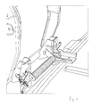
- FIGS. 1 to 4 show a first preferred embodiment of a removable seat assembly 1, which is usually arranged in the second or third row of seats of a van.
- the removable seat arrangement 1 comprises a seat cushion with a seat cushion and an associated part of a first support structure 2 designed as a seat structure.
- the part of the first support structure 2 assigned to the seat cushion extends substantially within the seat cushion and gives it the mechanical stability required for the intended use. From the drawing it can be seen that the support structure 2 is formed in the manner of a frame or framework.
- the framework includes a front and a rear tubular cross strut 3,4 and the cross struts connecting Side cheeks 5,6.
- the first support structure 2 continues in a number of projecting support struts 7, which expedient at approximately right angles or with a slight inclination to the plane of Support surface of the seat cushion are aligned.
- the support struts 7 are at the edge of the front cross member 3 in the region of the side walls 5, 6 executed.
- the removable seat arrangement or the support struts 7 of the first support structure 2 comprise a base 8 and serve for the detachable connection of the collapsible seat arrangement 1 to a vehicle body.
- connection of the seat arrangement 1 in the front region is set up to enable a pivoting of the seat structure in the region of the front portion of the seat cushion on the pedestals 8 about a pivot axis A.
- This is in the FIG. 2 represented by the arrow 9.
- the base 8 can be both a component associated with the seat assembly 1 and a component associated with the inner bottom of the motor vehicle.
- a spring means 10 for biasing the seat structure 1 with respect to a pivoting movement according to arrow 9 is provided to the stowage position.
- spring devices known spring means, for example, coil springs, torsion springs, etc. can be used.
- limiting means for limiting the action of the spring means 10 on a first portion of the pivoting movement after leaving the stowed position are provided.
- coil springs are provided as spring means, which are each arranged on a bearing axis 15 on both sides of the base 8 and the bearing points. An end portion 16 of the coil spring 10 is fixed to the base 8 and the bearing point of the first support structure 2, the second end portion 17 of the coil spring 10 is supported on a vehicle floor side connecting part 12 from.
- the support struts 7 are designed as front bearing points and each have a connecting part 11 for connection to an associated vehicle floor-side connecting part 12.
- the connection is designed such that a pivoting of the first support structure 2 is possible.
- the connection between the first connecting part 11 and the associated vehicle floor-side connecting part 12 can be blocked by a rotary lock 17 against the intended pivoting.
- the turnstile 17 may include locking and unlocking.
- the locking and unlocking means are formed as locks comprising a catch and an associated pawl arrangement.
- the releasable locking of the first support structure 2 with respect to a pivoting results in a known manner by an interaction of a arranged on the first connecting part of the latch with a disposed on the vehicle floor side connecting part 9 closing member, namely a transverse pin 18th
- the seat assembly 1 In the rear region of the seat cushion in the region of the side cheeks 5, 6 are further means for releasably connecting the seat assembly 1 to the vehicle body formed. These means each have a connecting part for releasable connection to an associated vehicle-floor-side connecting part. In the in Fig.1 shown use position, the connection between the first connecting part and the associated vehicle floor side connecting part via known locking elements and Entriegelunsele 19 is formed.
- the locking and unlocking means 19 are formed as locks comprising a latch and an associated pawl arrangement.
- the releasable locking of the rear portion of the support structure 2 on the inner bottom of the motor vehicle results in a known manner by an interaction of a arranged on the first connection part of the locking latch with a disposed on the vehicle floor side connecting member closing member, namely a transverse bolt.
- the seat assembly 1 further comprises a backrest 13, which is adjustably connected in the rear region of the seat cushion.
- the backrest 13 has a second support structure, which is likewise designed in the manner of a frame or framework.
- the second support structure is adapted to support the backrest cushion and mechanically stiffen.
- the backrest cushion is also not shown in the drawings. From the representation of Figures 1 and 2 can be seen that the backrest is connected in its peripheral region via a pivotable hinge connection 14 on the side walls 5, 6 of the seat cushion.
- the seat assembly 1 can first be placed in a so-called first stowage position. This storage location is in the Fig. 5 shown.
- the connection of the backrest 13 is unlocked at the first support structure and folded forward on the seat cushion by a not shown in detail and described unlocking device.
- the backrest points 13 a nearly horizontal position.
- the locking of the connecting parts of the connection of the seat assembly in the rear region of the side walls 5, 6 of the first support structure can be unlocked on the associated vehicle floor-side connecting part.
- the seat assembly 1 can now be pivoted starting from this position with the seat cushion folded backrest in the desired storage position (package order).
- the seat assembly 1 performs a pivoting movement about the pivot axis A arranged in the front lower region of the seat structure. This pivoting movement is in the FIG. 2 represented by the arrow S. Due to the arrangement and configuration of the spring device described below, by means of which the seat structure is prestressed with respect to the pivoting movement, a facilitated movement of the seat structure from the use into the stowage position and subsequent removal of the seat arrangement 1 is possible.
- the seat assembly 1 according to Fig. 2 is in the collapsed setting (stowage position)
- the seat cushion and the backrest assume an approximately upright stacked position.
- the position of use is in the Fig. 1 shown and is the usual during use of the motor vehicle seat position of the vehicle seat with the backrest folded up.
- the collapsed seat assembly 1 can now be removed from the vehicle interior. Due to the pivotal movement of the seat structure about the pivot axis A, the locking axis blocked by the locking lever are released, and a removal of the complete seat assembly from the vehicle-side connecting part is possible. The removal of the seat assembly 1 is further easily possible due to the cancellation of the spring preload.
- the spring device comprises a torsion spring 20 extending preferably along the swiveling axis A of the articulated connection of the seat structure to the base 8. This is in the area of the front Cross strut 3 a parallel below the transverse strut extending the bearing points of the base 8 connecting winding axis 21 is arranged.
- An end portion of the leg spring is connected to the seat structure, that other end 22 of the leg spring is supported on the vehicle floor side connection point 12 from.
- the winding axis coincides with the pivot axis of the seat structure, it is advantageous that the end region of the support leg spring does not change on the ground-side connection point.
- the first section includes the overturning of the center of gravity of the seat structure and the seat back resting thereon above the top dead center.
- This top dead center is defined as the gravitational impressed torques.
- These are designed as arranged on the seat structure stops 23 which strike at a pivoting of the seat structure according to a predetermined pivoting angle to the second end portion 22 of the leg spring and cancel the bottom-side support of the leg spring.
- the spring action is released and the seat structure can be further pivoted in the further pivoting without spring preload and then very easy to remove. This situation is in the Fig. 7 shown.
- end stops 24 are provided in the region of the bearing points, which block the further rotation of the seat structure from a certain maximum pivoting angle.
- the end stops on the vehicle floor side surfaces which are preferably provided in a bottom-side recess. This is not shown in the drawing.
Landscapes
- Engineering & Computer Science (AREA)
- Aviation & Aerospace Engineering (AREA)
- Transportation (AREA)
- Mechanical Engineering (AREA)
- Seats For Vehicles (AREA)
Abstract
Description
- Die vorliegende Erfindung betrifft eine entnehmbare Sitzanordnung für ein Kraftfahrzeug und insbesondere für einen Kleinbus oder Kastenwagen.
- In Kombinations-Kraftfahrzeugen, die üblicherweise als "Van" bezeichnet werden, Kleinbussen oder Kastenwagen ist die zweite bzw. dritte Sitzreihe häufig zusammenlegbar ausgestaltet. Dies ermöglicht ein Einsteigen und Aussteigen der Fahrzeuginsassen der dritten Sitzreihe. Des Weiteren wird eine einfache Vergrößerung des Gepäckraums ohne Ausbau der Sitzreihe möglich. Eine derartige Sitzanordnung zeigt beispielsweise die Druckschrift
US 2002 / 0027383 A1 . In der Regel wird beim Zusammenlegen der Sitzreihe die Rückenlehne über die Sitzfläche abgelegt und der gesamte Sitz anschließend über eine Schwenkachse im vorderen Bereich der Sitzbasis nach vorne aufgestellt. Üblicherweise sind derartige Sitzanordnungen auch entnehmbar ausgeführt, um eine möglichst variable Gestaltung des Innenraums des Kraftfahrzeugs erzielen zu können. - Es ist eine Aufgabe der vorliegenden Erfindung, eine entnehmbare Sitzanordnung für ein Kraftfahrzeug zu schaffen, die eine verbesserte Handhabung für den Fahrzeugnutzer beim Zusammenlegen in die Verstauposition und Herausnehmen der Sitzanordnung ermöglicht.
- Diese Aufgabe löst die vorliegende Erfindung durch eine entnehmbare Sitzanordnung mit den Merkmalen des Anspruch 1.
- Noch weitere vorteilhafte Ausgestaltungen der vorliegenden Erfindung sind in den jeweiligen Unteransprüchen angegeben.
- Bevorzugte Ausführungsformen der vorliegenden Erfindung werden nachfolgend beispielshalber beschrieben, wobei auf die anhängenden Zeichnungen Bezug genommen wird. Darin zeigen:
- Fig. 1
- eine perspektivische schematische Ansicht einer Sitzstruktur einer Sitzanordnung der vorliegenden Erfindung in einer Gebrauchslage;
- Fig. 2
- eine perspektivische schematische rückwärtige Ansicht der Sitzstruktur gemäß
Fig.1 in einer Verstaulage; - Fig. 3a
- eine perspektivische Detailansicht der Anbindungsstelle des Sockels, sowie eine Spiralfeder als Federeinrichtung in einer Ansicht von vorne;
- Fig. 3b
- eine perspektivische Detailansicht der Anbindungsstelle gemäß
Fig. 3a in einer rückwärtigen Ansicht; - Fig. 4
- eine perspektivische schematische Detailansicht des Bereichs des vorderen Abschnitts des Sitzkissens und der Anbindungsstelle in der Verstauposition;
- Fig. 5
- eine perspektivische schematische Ansicht einer weiteren Ausführungsvarianten einer Sitzstruktur einer Sitzanordnung in einer ersten Verstaulage mit nach vorne geklappter Rückenlehne;
- Fig. 6
- eine perspektivische schematische Seitenansicht eines Details der Sitzanordnung nach
Fig. 5 im Bereich des vorderen Abschnitts des Sitzkissens und der Verschwenkachse mit Federeinrichtung und Begrenzungsmittel; - Fig. 7
- eine perspektivische Detailansicht der Federeinrichtung gemäß
Fig. 6 mit einer Drehführung - Fig. 8
- die Detailansicht der
Fig. 7 in einer Vorderansicht, und - Fig. 9
- eine perspektivische schematische Seitenansicht des Bereichs der vorderen Anbindungsstelle.
- Die Figuren
Figuren 1 bis 4 zeigen eine erste bevorzugte Ausführungsform einer entnehmbaren Sitzanordnung 1, die üblicherweise in der zweiten oder dritten Sitzreihe eines Vans angeordnet ist. - Die entnehmbare Sitzanordnung 1 umfasst ein Sitzkissen mit einem Sitzpolster und einem zugeordneten Teil einer als Sitzstruktur ausgebildeten ersten Tragstruktur 2. Der dem Sitzkissen zugeordnete Teil der ersten Tragstruktur 2 erstreckt sich im Wesentlichen innerhalb des Sitzpolsters und verleiht diesem die für den vorgesehenen Gebrauch erforderliche mechanische Stabilität. Aus der Zeichnung lässt sich erkennen, dass die Tragstruktur 2 in der Art eines Gestells oder Rahmenwerks ausgebildet ist. Das Rahmenwerk umfasst dabei eine vordere und eine hintere rohrförmige Querstrebe 3,4 sowie die Querstreben verbindende Seitenwangen 5,6. Vorzugsweise im vorderen (der in Fahrtrichtung weisende Bereich, dargestellt durch den Pfeil P) unteren Bereich des Sitzkissens setzt sich die erste Tragstruktur 2 in einer Anzahl von abstehenden Stützstreben 7 fort, die zweckmäßig in annähernd rechtem Winkel oder mit leichter Neigung dazu gegenüber der Ebene der Auflagefläche des Sitzpolsters ausgerichtet sind. Die Stützstreben 7 sind randseitig an der vorderen Querstrebe 3 im Bereich der Seitenwangen 5, 6 ausgeführt. Die entnehmbare Sitzanordnung bzw. die Stützstreben 7 der ersten Tragstruktur 2 umfassen einen Sockel 8 und dienen zur lösbaren Anbindung der zusammenlegbaren Sitzanordnung 1 an einem Fahrzeugkörper. Des Weiteren ist diese Anbindung der Sitzanordnung 1 im vorderen Bereich dazu eingerichtet, ein Verschwenken der Sitzstruktur im Bereich des vorderen Abschnitts des Sitzkissens an den Sockeln 8 um eine Verschwenkachse A zu ermöglichen. Dies ist in der
Figur 2 durch den Pfeil 9 dargestellt. Der Sockel 8 kann dabei sowohl ein der Sitzanordnung 1 zugeordnetes Bauteil, als auch ein dem Innenboden des Kraftfahrzeugs zugeordnetes Bauteil sein. - Um ein Verschwenken der Sitzanordnung 1 von der Gebrauchslage in die Verstaulage zu erleichtern, ist eine Federeinrichtung 10 zum Vorspannen der Sitzstruktur 1 in Bezug auf eine Verschwenkbewegung gemäß Pfeil 9 zu der Verstaulage vorgesehen. Als Federeinrichtungen können bekannte Federmittel beispielsweise Spiralfedern, Schenkelfedern etc. eingesetzt werden. Weiterhin sind Begrenzungsmittel zum Begrenzen der Wirkung der Federeinrichtung 10 auf einem ersten Abschnitt der Verschwenkbewegung nach dem Verlassen der Verstauposition vorgesehen. Im gezeigten Ausführungsbeispiel sind als Federmittel Spiralfedern vorgesehen, die jeweils auf einer Lagerachse 15 beidseits der Sockel 8 bzw. der Lagerstellen angeordnet sind. Ein Endbereich 16 der Spiralfeder 10 ist an dem Sockel 8 bzw. der Lagerstelle der ersten Tragstruktur 2 festgelegt, der zweite Endbereich 17 der Spiralfeder 10 stützt sich auf einem fahrzeugbodenseitigen Verbindungsteil 12 ab.
- Die Stützstreben 7 sind als vordere Lagerstellen ausgeführt und weisen jeweils ein Verbindungsteil 11 zur Anbindung an einem zugeordneten fahrzeugbodenseitigen Verbindungsteil 12 auf. Die Verbindung ist derart ausgestaltet, dass ein Verschwenken der ersten Tragstruktur 2 möglich ist. In der in
Fig.1 dargestellten Gebrauchslage ist die Verbindung zwischen dem ersten Verbindungsteil 11 und dem zugeordneten fahrzeugbodenseitigen Verbindungsteil 12 durch eine Drehsperre 17 gegenüber dem vorgesehenen Verschwenken blockierbar. Die Drehsperre 17 kann dabei Verriegelungs- und Entriegelungselemente umfassen. Vorzugsweise sind die Verriegelungs- und Entriegelungsmittel als Schlösser ausgebildet, die eine Drehfalle und eine zugeordnete Sperrklinkenanordnung umfassen. Die lösbare Verriegelung der ersten Tragstruktur 2 gegenüber einem Verschwenken ergibt sich dabei in bekannter Weise durch ein Zusammenwirken einer an dem ersten Verbindungsteil angeordneten Schließfalle mit einem an dem fahrzeugbodenseitigen Verbindungsteil 9 angeordneten Schließglied, nämlich einem Querbolzen 18. - Im hinteren Bereich des Sitzkissens im Bereich der Seitenwangen 5, 6 sind weiterhin Mittel zur lösbaren Anbindung der Sitzanordnung 1 an dem Fahrzeugkörper ausgebildet. Diese Mittel weisen jeweils ein Verbindungsteil zur lösbaren Anbindung an einem zugeordneten fahrzeugbodenseitigen Verbindungsteil auf. In der in
Fig.1 dargestellten Gebrauchslage ist die Verbindung zwischen dem ersten Verbindungsteil und dem zugeordneten fahrzeugbodenseitigen Verbindungsteil über bekannte Verriegelungselemente und Entriegelunselemente 19 ausgebildet. Vorzugsweise sind die Verriegelungs- und Entriegelungsmittel 19 als Schlösser ausgebildet, die eine Schließfalle und eine zugeordnete Sperrklinkenanordnung umfassen. Die lösbare Verriegelung des hinteren Bereichs der Tragstruktur 2 an dem Innenboden des Kraftfahrzeugs ergibt sich dabei in bekannter Weise durch ein Zusammenwirken einer an dem ersten Verbindungsteil angeordneten Schließfalle mit einem an dem fahrzeugbodenseitigen Verbindungsteil angeordneten Schließglied, nämlich einem Querbolzen. - Die Sitzanordnung 1 weist des Weiteren eine Rückenlehne 13 auf, die im hinteren Bereich des Sitzkissens verstellbar angebunden ist. Die Rückenlehne 13 weist eine zweite Tragstruktur auf, die ebenfalls in der Art eines Gestells oder Rahmenwerks ausgebildet ist. Die zweite Tragstruktur ist dazu ausgebildet das Rückenlehnenpolster zu tragen und mechanisch zu versteifen. Das Rückenlehnenpolster ist ebenfalls in den Zeichnungen nicht dargestellt. Aus der Darstellung der
Figuren 1 und 2 kann man erkennen, dass die Rückenlehne in ihrem randseitigen Bereich über eine verschwenkbare Gelenkverbindung 14 an den Seitenwangen 5, 6 des Sitzkissens angebunden ist. - Zur Vergrößerung des Stauraums des Kraftfahrzeugs kann die Sitzanordnung 1 zunächst in eine sogenannte erste Verstaulage gebracht werden. Diese Verstaulage ist in der
Fig. 5 dargestellt. Hierfür wird zunächst durch eine nicht näher gezeigte und beschriebene Entriegelungsvorrichtung die Anbindung der Rückenlehne 13 an der ersten Tragstruktur entriegelt und nach vorne auf das Sitzkissen geklappt. In dieser Position weist die Rückenlehne 13 eine nahezu waagrechte Position auf. Nachdem diese erste Verstaulage erreicht ist, kann die Arretierung der Verbindungsteile der Anbindung der Sitzanordnung im hinteren Bereich der Seitenwangen 5, 6 der ersten Tragstruktur an dem zugeordneten fahrzeugbodenseitigen Verbindungsteil entriegelt werden. Die Sitzanordnung 1 kann nun ausgehend von dieser Position mit auf das Sitzkissen geklappter Rückenlehne in die gewünschte Verstaulage (Packagestellung) verschwenkt werden. Dabei lösen sich zunächst die Verbindungsteile der hinteren Anbindungsstellen der ersten Tragstruktur aus der fahrzeugbodenseitigen Verbindung und die Sitzstruktur wird im hinteren Bereich angehoben. Die Sitzanordnung 1 führt eine Schwenkbewegung um die im vorderen unteren Bereich der Sitzstruktur angeordneten Verschwenkachse A aus. Diese Schwenkbewegung ist in derFigur 2 durch den Pfeil S dargestellt. Aufgrund der nachfolgend beschriebenen Anordnung und Ausgestaltung der Federeinrichtung, durch die die Sitzstruktur in Bezug auf die Verschwenkbewegung vorgespannt ist, ist ein erleichtertes Verbringen der Sitzstruktur aus der Gebrauchs- in die Verstaulage und anschließendes Herausnehmen der Sitzanordnung 1 möglich. Wenn sich die Sitzanordnung 1 gemäßFig. 2 in der zusammengelegten Einstellung (Verstaulage) befindet, nehmen das Sitzkissen und die Rückenlehne eine ungefähr aufrecht gestapelte Stellung ein. Die Gebrauchslage ist in derFig. 1 dargestellt und ist die beim Gebrauch des Kraftfahrzeugsitzes übliche Position des Kraftfahrzeugsitzes mit hochgeklappter Rückenlehne. - Zur Vergrößerung des Gepäckraums kann nun die zusammengelegte Sitzanordnung 1 aus dem Fahrzeuginnenraum entnommen werden. Aufgrund der Schwenkbewegung der Sitzstruktur um die Verschwenkachse A werden die über Verriegelungshebel blockierte Lagerachse freigegeben, und ein Herausnehmen der kompletten Sitzanordnung aus dem fahrzeugseitigen Verbindungsteil ist möglich. Das Herausnehmen der Sitzanordnung 1 ist des Weiteren aufgrund der Aufhebung der Federvorspannung einfach möglich.
- Die in den
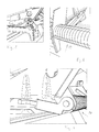
Figuren 5-9 dargestellte weitere Ausführungsvariante einer erfindungsgemäßen Sitzanordnung 1' unterscheidet sich von der zuvor beschriebenen Sitzanordnung in der Ausführungsform und Anordnung der Federeinrichtung 10. Gleiche bereits zuvor beschriebene Teile werden nachfolgend mit den gleichen Bezugszeichen benannt und in den Figuren gekennzeichnet. Aus denFiguren 5-7 ist zu erkennen, dass die Federeinrichtung eine vorzugsweise entlang der Verschwenkachse A der gelenkigen Anbindung der Sitzstruktur am Sockel 8 verlaufende Torsionsfeder 20 umfasst. Hierzu ist im Bereich der vorderen Querstrebe 3 eine parallel unterhalb der Querstrebe verlaufende die Lagerstellen der Sockel 8 verbindende Wickelachse 21 angeordnet. Diese Wickelachse 21 ist fluchtend zu der Verschwenkachse A vorgesehen und dient der Aufnahme der Schenkelfeder als Federeinrichtung 10. Ein Endbereich der Schenkelfeder ist dabei mit der Sitzstruktur verbunden, dass andere Ende 22 der Schenkelfeder stützt sich an der fahrzeugbodenseitigen Anbindungsstelle 12 ab. Bei der Ausführungsform, bei der die Wickelachse mit der Schwenkachse der Sitzstruktur zusammenfällt, ist es von Vorteil, dass sich der Endbereich der Abstützung Schenkelfeder auf der bodenseitigen Anbindungsstelle nicht verändert. - Des Weiteren sind aus der Darstellung der
Figur 7 die Begrenzungsmittel 23 zum Begrenzen der Wirkung der Federeinrichtung 10 auf einem ersten Abschnitt der Verschwenkbewegung nach dem Verlassen der Verstauposition dargestellt. Hierbei schließt der erste Abschnitt das Überschlagen des Schwerpunkts der Sitzstruktur und der darauf abgelegten Rückenlehne über den oberen Totpunkt ein. Dieser obere Totpunkt ist definiert als der von der Schwerkraft eingeprägten Drehmomente. Diese sind als an der Sitzstruktur angeordnete Anschläge 23 ausgebildet, die bei einem Verschwenken der Sitzstruktur nach einem vorbestimmten Verschwenkwinkel an den zweiten Endbereich 22 der Schenkelfeder anschlagen und die bodenseitige Abstützung der Schenkelfeder aufheben. Hierdurch wird die Federwirkung aufgehoben und die Sitzstruktur lässt sich im weiteren Verschwenkbereich ohne Federvorspannung weiter verschwenken und anschließend sehr einfach herausnehmen. Diese Situation ist in derFig. 7 dargestellt. - Diese Anschläge 23 laufen innerhalb des vom Außendurchmesser der Federeinrichtung vorgegebenen Zylinders um. Hierdurch wird eine platzsparende Bauweise erzielt. Des Weiteren ist der am Sockel 8 abstützbare Schenkel 22 der Federeinrichtung 10 in einer Drehführung 25 mit definierter Schwenkachse "B" gehalten. Diese Schwenkachse fällt vorzugsweise mit der Schwenkachse A der Sitzstruktur zusammen.
- Um eine Verschwenkbegrenzung der Sitzstruktur zu erzielen, sind im Bereich der Lagerstellen Endanschläge 24 vorgesehen, die ab einem bestimmten maximalen Verschwenkwinkel die weitere Drehung der Sitzstruktur blockieren. Hierzu schlagen die Endanschläge an fahrzeugbodenseitige Flächen an, die vorzugsweise in einer bodenseitigen Vertiefung vorgesehen sind. Dies ist zeichnerisch nicht näher dargestellt.
Claims (9)
- Entnehmbare Sitzanordnung (1, 1') für ein Kraftfahrzeug, aufweisend- einen Sockel (8) mit Verriegelungsmitteln (17, 19) zur lösbaren Anbindung an den Innenboden eines Kraftfahrzeugs,- eine Sitzstruktur (2) mit einem daran angeordneten Sitzkissen und einer daran angeordneten verstellbaren und auf dem Sitzkissen ablegbaren Rückenlehne (13), wobei die Sitzstruktur (2) im Bereich des vorderen Abschnitts (3) des Sitzkissens an dem Sockel (8) oder dem Fahrzeugboden gelenkig um eine Verschwenkachse "A" verschwenkbar angeschlagen ist, um nach dem Ablegen der Rückenlehne (13) aus der Gebrauchslage in eine aufrechte oder überkippte Verstaulage verlagerbar zu sein,- eine Federeinrichtung (10) zum Vorspannen der Sitzstruktur (2) in Bezug auf eine Verschwenkbewegung zu der Verstaulage, um dem Benutzer das Verbringen der Sitzstruktur (2) aus der Gebrauchs- in die Verstaulage zu erleichtern, und- Begrenzungsmittel (23) zum Begrenzen der Wirkung der Federeinrichtung (10) auf einem ersten Abschnitt der Verschwenkbewegung nach dem Verlassen der Verstauposition.
- Entnehmbare Sitzanordnung (1, 1') gemäß Anspruch 1, wobei der erste Abschnitt das Überschlagen des Schwerpunkts der Sitzstruktur (2) und der darauf abgelegten Rückenlehne (13) über den oberen Totpunkt einschließt.
- Entnehmbare Sitzanordnung (1, 1') gemäß Anspruch 1 oder Anspruch 2, wobei die Federeinrichtung (10) eine vorzugsweise entlang der Verschwenkachse A der gelenkigen Anbindung der Sitzstruktur (2) am Sockel (8) oder dem Fahrzeugboden verlaufende Torsionsfeder und insbesondere eine Drehstabfeder, eine Schraubentorsionsfeder oder eine Spiraltorsionsfeder umfasst.
- Entnehmbare Sitzanordnung (1, 1') gemäß einem der Ansprüche 1 bis 3, wobei die Begrenzungsmittel (23) eine Seite der Abstützung der Federeinrichtung (10) am Sockel (8) und an der Sitzstruktur bzw. dem Fahrzeugboden nach dem Überschreiten des ersten Abschnitts aufheben.
- Entnehmbare Sitzanordnung nach einem der Ansprüche 1 bis 4, wobei die Federeinrichtung (10) mit einem abstehenden Schenkel am Sockel (8) oder einem fahrzeugbodenseitigen Verbindungsteil (12) abstützbar ist.
- Entnehmbare Sitzanordnung gemäß Anspruch 5, wobei die Abstützung der Federeinrichtung am Sockel bzw. dem fahrzeugbodenseitigen Verbindungsteil (12) durch einen von der Sitzbasis mitbewegten Anschlag (23) aufgehoben wird.
- Entnehmbare Sitzanordnung gemäß Anspruch 6, wobei der Anschlag (23) innerhalb des vom Außendurchmesser der Federeinrichtung (10) vorgegebenen Zylinders umläuft.
- Entnehmbare Sitzanordnung nach einem der Ansprüche 4 bis 6, wobei der am Sockel bzw. dem fahrzeugseitigen Verbindungsteil abstützbare Schenkel der Federeinrichtung (10) in einer Drehführung (25) mit definierter Schwenkachse "B" gehalten ist.
- Entnehmbare Sitzanordnung gemäß Anspruch 8, wobei die Schwenkachse "B" der Drehführung (25) mit der Schwenkachse "A" der Sitzstruktur zusammen fällt.
Applications Claiming Priority (1)
| Application Number | Priority Date | Filing Date | Title |
|---|---|---|---|
| DE102011107909A DE102011107909A1 (de) | 2011-07-03 | 2011-07-03 | Kraftfahrzeugsitz |
Publications (2)
| Publication Number | Publication Date |
|---|---|
| EP2543538A1 true EP2543538A1 (de) | 2013-01-09 |
| EP2543538B1 EP2543538B1 (de) | 2016-01-20 |
Family
ID=46168299
Family Applications (1)
| Application Number | Title | Priority Date | Filing Date |
|---|---|---|---|
| EP12169981.3A Active EP2543538B1 (de) | 2011-07-03 | 2012-05-30 | Kraftfahrzeugsitz |
Country Status (2)
| Country | Link |
|---|---|
| EP (1) | EP2543538B1 (de) |
| DE (1) | DE102011107909A1 (de) |
Cited By (1)
| Publication number | Priority date | Publication date | Assignee | Title |
|---|---|---|---|---|
| CN105438036A (zh) * | 2015-12-08 | 2016-03-30 | 重庆宏立至信汽车部件制造有限公司 | 一种带地板锁的后排座框骨架总成 |
Families Citing this family (1)
| Publication number | Priority date | Publication date | Assignee | Title |
|---|---|---|---|---|
| US11332050B1 (en) * | 2021-02-12 | 2022-05-17 | Ford Global Technologies, Llc | Mechanism for seating assembly latch assembly |
Citations (4)
| Publication number | Priority date | Publication date | Assignee | Title |
|---|---|---|---|---|
| JP2000102438A (ja) * | 1998-07-30 | 2000-04-11 | Chuo Spring Co Ltd | 衝撃緩和装置 |
| WO2000021778A1 (en) * | 1998-10-09 | 2000-04-20 | Magna Seating Systems Inc. | Automated fold and tumble vehicle seat assembly |
| US20020027383A1 (en) | 2000-09-06 | 2002-03-07 | Honda Giken Kogyo Kabushiki Kaisha | Locking device for folding seat |
| DE102009033035A1 (de) * | 2009-07-02 | 2011-01-13 | Koki Technik Seating Systems Gmbh | Lehnenauswurf |
Family Cites Families (2)
| Publication number | Priority date | Publication date | Assignee | Title |
|---|---|---|---|---|
| US5671965A (en) * | 1996-03-26 | 1997-09-30 | Atoma International, Inc. | Tumble seat with displaceable side handle release |
| US7073862B2 (en) * | 2003-07-31 | 2006-07-11 | Intier Automotive Inc. | Tumble seat assembly having locking strut |
-
2011
- 2011-07-03 DE DE102011107909A patent/DE102011107909A1/de not_active Withdrawn
-
2012
- 2012-05-30 EP EP12169981.3A patent/EP2543538B1/de active Active
Patent Citations (4)
| Publication number | Priority date | Publication date | Assignee | Title |
|---|---|---|---|---|
| JP2000102438A (ja) * | 1998-07-30 | 2000-04-11 | Chuo Spring Co Ltd | 衝撃緩和装置 |
| WO2000021778A1 (en) * | 1998-10-09 | 2000-04-20 | Magna Seating Systems Inc. | Automated fold and tumble vehicle seat assembly |
| US20020027383A1 (en) | 2000-09-06 | 2002-03-07 | Honda Giken Kogyo Kabushiki Kaisha | Locking device for folding seat |
| DE102009033035A1 (de) * | 2009-07-02 | 2011-01-13 | Koki Technik Seating Systems Gmbh | Lehnenauswurf |
Cited By (1)
| Publication number | Priority date | Publication date | Assignee | Title |
|---|---|---|---|---|
| CN105438036A (zh) * | 2015-12-08 | 2016-03-30 | 重庆宏立至信汽车部件制造有限公司 | 一种带地板锁的后排座框骨架总成 |
Also Published As
| Publication number | Publication date |
|---|---|
| EP2543538B1 (de) | 2016-01-20 |
| DE102011107909A1 (de) | 2013-01-03 |
Similar Documents
| Publication | Publication Date | Title |
|---|---|---|
| DE10196288B4 (de) | Sitzverstellung und Bodenarretierung mit Blockierung | |
| DE60304991T2 (de) | Kopfstütze für kraftfahrzeuge | |
| EP2217467B1 (de) | Kraftfahrzeugsitz | |
| DE102006017797B4 (de) | Fahrzeugsitz-Löseanordnung | |
| DE102016202513B4 (de) | Fahrzeugsitz, insbesondere Kraftfahrzeugsitz | |
| DE102009021211A1 (de) | Fahrzeugsitz | |
| DE102011055585A1 (de) | Sitzeinrichtung für ein Kraftfahrzeug | |
| WO2005075241A1 (de) | Kopfstützenanordnung | |
| DE112018004025T5 (de) | Bewegliche Grundplattenabdeckung und innenliegendes Sperrgatter eines Liftsystems für ein motorisiertes Fahrzeug | |
| WO2013056792A1 (de) | Verriegelungs- und neigungsverstellanordnung, insbesondere lehnenschloss | |
| DE102015223221A1 (de) | Fahrzeugsitz | |
| EP0928717B1 (de) | Verstelleinrichtung für eine Fahrzeugsitz-Rückenlehne | |
| DE102007063565A1 (de) | Kraftfahrzeugsitz | |
| DE102007052529B4 (de) | Ein Sitz und Sitzanordnung in einem Kraftfahrzeug | |
| DE102010046562B4 (de) | Sitz oder Sitzanlage für ein Kraftfahrzeug und insbesondere einen Lieferwagen | |
| EP2543538B1 (de) | Kraftfahrzeugsitz | |
| EP3339091A1 (de) | Fahrzeugsitz mit einem sicherheitsgurtsystem | |
| EP3016819B1 (de) | Sitz und deren verwendung in einem gepanzerten fahrzeug | |
| EP1281566A2 (de) | Fahrzeugsitz mit Bodenstellung | |
| DE102007049838B3 (de) | Rückenlehne für ein Fahrzeug | |
| DE102005003603B4 (de) | Fahrzeugsitz mit einem rückwärtsgerichteten Faltmechanismus | |
| DE19945331C2 (de) | Fondsitz mit Kopfstütze | |
| DE2441398A1 (de) | Einrichtung zum verriegeln und entriegeln insbesondere eines am fahrzeugaufbau eines kraftfahrzeuges angeordneten fahrzeugsitzes | |
| DE102016213572A1 (de) | Schwenkvorrichtung für einen fahrzeugsitz | |
| DE102007021839A1 (de) | Vorrichtung zur lösbaren Verriegelung eines verschwenkbaren Fahrzeugteils an einer karosserieseitigen Befestigungsstelle |
Legal Events
| Date | Code | Title | Description |
|---|---|---|---|
| PUAI | Public reference made under article 153(3) epc to a published international application that has entered the european phase |
Free format text: ORIGINAL CODE: 0009012 |
|
| AK | Designated contracting states |
Kind code of ref document: A1 Designated state(s): AL AT BE BG CH CY CZ DE DK EE ES FI FR GB GR HR HU IE IS IT LI LT LU LV MC MK MT NL NO PL PT RO RS SE SI SK SM TR |
|
| AX | Request for extension of the european patent |
Extension state: BA ME |
|
| 17P | Request for examination filed |
Effective date: 20130614 |
|
| RBV | Designated contracting states (corrected) |
Designated state(s): AL AT BE BG CH CY CZ DE DK EE ES FI FR GB GR HR HU IE IS IT LI LT LU LV MC MK MT NL NO PL PT RO RS SE SI SK SM TR |
|
| GRAP | Despatch of communication of intention to grant a patent |
Free format text: ORIGINAL CODE: EPIDOSNIGR1 |
|
| INTG | Intention to grant announced |
Effective date: 20150930 |
|
| GRAS | Grant fee paid |
Free format text: ORIGINAL CODE: EPIDOSNIGR3 |
|
| GRAA | (expected) grant |
Free format text: ORIGINAL CODE: 0009210 |
|
| AK | Designated contracting states |
Kind code of ref document: B1 Designated state(s): AL AT BE BG CH CY CZ DE DK EE ES FI FR GB GR HR HU IE IS IT LI LT LU LV MC MK MT NL NO PL PT RO RS SE SI SK SM TR |
|
| REG | Reference to a national code |
Ref country code: GB Ref legal event code: FG4D Free format text: NOT ENGLISH |
|
| REG | Reference to a national code |
Ref country code: CH Ref legal event code: EP |
|
| REG | Reference to a national code |
Ref country code: IE Ref legal event code: FG4D Free format text: LANGUAGE OF EP DOCUMENT: GERMAN |
|
| REG | Reference to a national code |
Ref country code: AT Ref legal event code: REF Ref document number: 771538 Country of ref document: AT Kind code of ref document: T Effective date: 20160215 |
|
| REG | Reference to a national code |
Ref country code: DE Ref legal event code: R096 Ref document number: 502012005764 Country of ref document: DE |
|
| REG | Reference to a national code |
Ref country code: FR Ref legal event code: PLFP Year of fee payment: 5 |
|
| REG | Reference to a national code |
Ref country code: LT Ref legal event code: MG4D Ref country code: NL Ref legal event code: MP Effective date: 20160120 |
|
| PG25 | Lapsed in a contracting state [announced via postgrant information from national office to epo] |
Ref country code: NL Free format text: LAPSE BECAUSE OF FAILURE TO SUBMIT A TRANSLATION OF THE DESCRIPTION OR TO PAY THE FEE WITHIN THE PRESCRIBED TIME-LIMIT Effective date: 20160120 |
|
| PG25 | Lapsed in a contracting state [announced via postgrant information from national office to epo] |
Ref country code: HR Free format text: LAPSE BECAUSE OF FAILURE TO SUBMIT A TRANSLATION OF THE DESCRIPTION OR TO PAY THE FEE WITHIN THE PRESCRIBED TIME-LIMIT Effective date: 20160120 Ref country code: NO Free format text: LAPSE BECAUSE OF FAILURE TO SUBMIT A TRANSLATION OF THE DESCRIPTION OR TO PAY THE FEE WITHIN THE PRESCRIBED TIME-LIMIT Effective date: 20160420 Ref country code: ES Free format text: LAPSE BECAUSE OF FAILURE TO SUBMIT A TRANSLATION OF THE DESCRIPTION OR TO PAY THE FEE WITHIN THE PRESCRIBED TIME-LIMIT Effective date: 20160120 Ref country code: IT Free format text: LAPSE BECAUSE OF FAILURE TO SUBMIT A TRANSLATION OF THE DESCRIPTION OR TO PAY THE FEE WITHIN THE PRESCRIBED TIME-LIMIT Effective date: 20160120 Ref country code: FI Free format text: LAPSE BECAUSE OF FAILURE TO SUBMIT A TRANSLATION OF THE DESCRIPTION OR TO PAY THE FEE WITHIN THE PRESCRIBED TIME-LIMIT Effective date: 20160120 Ref country code: GR Free format text: LAPSE BECAUSE OF FAILURE TO SUBMIT A TRANSLATION OF THE DESCRIPTION OR TO PAY THE FEE WITHIN THE PRESCRIBED TIME-LIMIT Effective date: 20160421 |
|
| PG25 | Lapsed in a contracting state [announced via postgrant information from national office to epo] |
Ref country code: LT Free format text: LAPSE BECAUSE OF FAILURE TO SUBMIT A TRANSLATION OF THE DESCRIPTION OR TO PAY THE FEE WITHIN THE PRESCRIBED TIME-LIMIT Effective date: 20160120 Ref country code: LV Free format text: LAPSE BECAUSE OF FAILURE TO SUBMIT A TRANSLATION OF THE DESCRIPTION OR TO PAY THE FEE WITHIN THE PRESCRIBED TIME-LIMIT Effective date: 20160120 Ref country code: IS Free format text: LAPSE BECAUSE OF FAILURE TO SUBMIT A TRANSLATION OF THE DESCRIPTION OR TO PAY THE FEE WITHIN THE PRESCRIBED TIME-LIMIT Effective date: 20160520 Ref country code: RS Free format text: LAPSE BECAUSE OF FAILURE TO SUBMIT A TRANSLATION OF THE DESCRIPTION OR TO PAY THE FEE WITHIN THE PRESCRIBED TIME-LIMIT Effective date: 20160120 Ref country code: BE Free format text: LAPSE BECAUSE OF NON-PAYMENT OF DUE FEES Effective date: 20160531 Ref country code: PT Free format text: LAPSE BECAUSE OF FAILURE TO SUBMIT A TRANSLATION OF THE DESCRIPTION OR TO PAY THE FEE WITHIN THE PRESCRIBED TIME-LIMIT Effective date: 20160520 Ref country code: SE Free format text: LAPSE BECAUSE OF FAILURE TO SUBMIT A TRANSLATION OF THE DESCRIPTION OR TO PAY THE FEE WITHIN THE PRESCRIBED TIME-LIMIT Effective date: 20160120 Ref country code: PL Free format text: LAPSE BECAUSE OF FAILURE TO SUBMIT A TRANSLATION OF THE DESCRIPTION OR TO PAY THE FEE WITHIN THE PRESCRIBED TIME-LIMIT Effective date: 20160120 |
|
| REG | Reference to a national code |
Ref country code: DE Ref legal event code: R097 Ref document number: 502012005764 Country of ref document: DE |
|
| PG25 | Lapsed in a contracting state [announced via postgrant information from national office to epo] |
Ref country code: EE Free format text: LAPSE BECAUSE OF FAILURE TO SUBMIT A TRANSLATION OF THE DESCRIPTION OR TO PAY THE FEE WITHIN THE PRESCRIBED TIME-LIMIT Effective date: 20160120 Ref country code: DK Free format text: LAPSE BECAUSE OF FAILURE TO SUBMIT A TRANSLATION OF THE DESCRIPTION OR TO PAY THE FEE WITHIN THE PRESCRIBED TIME-LIMIT Effective date: 20160120 |
|
| PLBE | No opposition filed within time limit |
Free format text: ORIGINAL CODE: 0009261 |
|
| STAA | Information on the status of an ep patent application or granted ep patent |
Free format text: STATUS: NO OPPOSITION FILED WITHIN TIME LIMIT |
|
| PG25 | Lapsed in a contracting state [announced via postgrant information from national office to epo] |
Ref country code: RO Free format text: LAPSE BECAUSE OF FAILURE TO SUBMIT A TRANSLATION OF THE DESCRIPTION OR TO PAY THE FEE WITHIN THE PRESCRIBED TIME-LIMIT Effective date: 20160120 Ref country code: SM Free format text: LAPSE BECAUSE OF FAILURE TO SUBMIT A TRANSLATION OF THE DESCRIPTION OR TO PAY THE FEE WITHIN THE PRESCRIBED TIME-LIMIT Effective date: 20160120 Ref country code: SK Free format text: LAPSE BECAUSE OF FAILURE TO SUBMIT A TRANSLATION OF THE DESCRIPTION OR TO PAY THE FEE WITHIN THE PRESCRIBED TIME-LIMIT Effective date: 20160120 Ref country code: CZ Free format text: LAPSE BECAUSE OF FAILURE TO SUBMIT A TRANSLATION OF THE DESCRIPTION OR TO PAY THE FEE WITHIN THE PRESCRIBED TIME-LIMIT Effective date: 20160120 |
|
| 26N | No opposition filed |
Effective date: 20161021 |
|
| PG25 | Lapsed in a contracting state [announced via postgrant information from national office to epo] |
Ref country code: LU Free format text: LAPSE BECAUSE OF FAILURE TO SUBMIT A TRANSLATION OF THE DESCRIPTION OR TO PAY THE FEE WITHIN THE PRESCRIBED TIME-LIMIT Effective date: 20160530 |
|
| REG | Reference to a national code |
Ref country code: CH Ref legal event code: PL |
|
| PG25 | Lapsed in a contracting state [announced via postgrant information from national office to epo] |
Ref country code: LI Free format text: LAPSE BECAUSE OF NON-PAYMENT OF DUE FEES Effective date: 20160531 Ref country code: CH Free format text: LAPSE BECAUSE OF NON-PAYMENT OF DUE FEES Effective date: 20160531 |
|
| REG | Reference to a national code |
Ref country code: IE Ref legal event code: MM4A |
|
| PG25 | Lapsed in a contracting state [announced via postgrant information from national office to epo] |
Ref country code: SI Free format text: LAPSE BECAUSE OF FAILURE TO SUBMIT A TRANSLATION OF THE DESCRIPTION OR TO PAY THE FEE WITHIN THE PRESCRIBED TIME-LIMIT Effective date: 20160120 Ref country code: BG Free format text: LAPSE BECAUSE OF FAILURE TO SUBMIT A TRANSLATION OF THE DESCRIPTION OR TO PAY THE FEE WITHIN THE PRESCRIBED TIME-LIMIT Effective date: 20160420 |
|
| REG | Reference to a national code |
Ref country code: FR Ref legal event code: PLFP Year of fee payment: 6 |
|
| PG25 | Lapsed in a contracting state [announced via postgrant information from national office to epo] |
Ref country code: IE Free format text: LAPSE BECAUSE OF NON-PAYMENT OF DUE FEES Effective date: 20160530 |
|
| REG | Reference to a national code |
Ref country code: FR Ref legal event code: PLFP Year of fee payment: 7 |
|
| PG25 | Lapsed in a contracting state [announced via postgrant information from national office to epo] |
Ref country code: HU Free format text: LAPSE BECAUSE OF FAILURE TO SUBMIT A TRANSLATION OF THE DESCRIPTION OR TO PAY THE FEE WITHIN THE PRESCRIBED TIME-LIMIT; INVALID AB INITIO Effective date: 20120530 Ref country code: CY Free format text: LAPSE BECAUSE OF FAILURE TO SUBMIT A TRANSLATION OF THE DESCRIPTION OR TO PAY THE FEE WITHIN THE PRESCRIBED TIME-LIMIT Effective date: 20160120 |
|
| PG25 | Lapsed in a contracting state [announced via postgrant information from national office to epo] |
Ref country code: MK Free format text: LAPSE BECAUSE OF FAILURE TO SUBMIT A TRANSLATION OF THE DESCRIPTION OR TO PAY THE FEE WITHIN THE PRESCRIBED TIME-LIMIT Effective date: 20160120 Ref country code: MC Free format text: LAPSE BECAUSE OF FAILURE TO SUBMIT A TRANSLATION OF THE DESCRIPTION OR TO PAY THE FEE WITHIN THE PRESCRIBED TIME-LIMIT Effective date: 20160120 Ref country code: MT Free format text: LAPSE BECAUSE OF FAILURE TO SUBMIT A TRANSLATION OF THE DESCRIPTION OR TO PAY THE FEE WITHIN THE PRESCRIBED TIME-LIMIT Effective date: 20160120 |
|
| REG | Reference to a national code |
Ref country code: AT Ref legal event code: MM01 Ref document number: 771538 Country of ref document: AT Kind code of ref document: T Effective date: 20170530 |
|
| PG25 | Lapsed in a contracting state [announced via postgrant information from national office to epo] |
Ref country code: AT Free format text: LAPSE BECAUSE OF NON-PAYMENT OF DUE FEES Effective date: 20170530 |
|
| PG25 | Lapsed in a contracting state [announced via postgrant information from national office to epo] |
Ref country code: AL Free format text: LAPSE BECAUSE OF FAILURE TO SUBMIT A TRANSLATION OF THE DESCRIPTION OR TO PAY THE FEE WITHIN THE PRESCRIBED TIME-LIMIT Effective date: 20160120 |
|
| PGFP | Annual fee paid to national office [announced via postgrant information from national office to epo] |
Ref country code: FR Payment date: 20210525 Year of fee payment: 10 |
|
| PGFP | Annual fee paid to national office [announced via postgrant information from national office to epo] |
Ref country code: GB Payment date: 20210525 Year of fee payment: 10 |
|
| GBPC | Gb: european patent ceased through non-payment of renewal fee |
Effective date: 20220530 |
|
| PG25 | Lapsed in a contracting state [announced via postgrant information from national office to epo] |
Ref country code: FR Free format text: LAPSE BECAUSE OF NON-PAYMENT OF DUE FEES Effective date: 20220531 |
|
| PG25 | Lapsed in a contracting state [announced via postgrant information from national office to epo] |
Ref country code: GB Free format text: LAPSE BECAUSE OF NON-PAYMENT OF DUE FEES Effective date: 20220530 |
|
| REG | Reference to a national code |
Ref country code: DE Ref legal event code: R082 Ref document number: 502012005764 Country of ref document: DE Representative=s name: EULER, MATTHIAS, DR., DE |
|
| PGFP | Annual fee paid to national office [announced via postgrant information from national office to epo] |
Ref country code: DE Payment date: 20250521 Year of fee payment: 14 |
|
| PGFP | Annual fee paid to national office [announced via postgrant information from national office to epo] |
Ref country code: TR Payment date: 20250526 Year of fee payment: 14 |