EP2541281A1 - Dispositif d'imagerie radiologique - Google Patents
Dispositif d'imagerie radiologique Download PDFInfo
- Publication number
- EP2541281A1 EP2541281A1 EP11747235A EP11747235A EP2541281A1 EP 2541281 A1 EP2541281 A1 EP 2541281A1 EP 11747235 A EP11747235 A EP 11747235A EP 11747235 A EP11747235 A EP 11747235A EP 2541281 A1 EP2541281 A1 EP 2541281A1
- Authority
- EP
- European Patent Office
- Prior art keywords
- controller
- image capturing
- housing
- grip
- radiographic image
- Prior art date
- Legal status (The legal status is an assumption and is not a legal conclusion. Google has not performed a legal analysis and makes no representation as to the accuracy of the status listed.)
- Granted
Links
- 238000003384 imaging method Methods 0.000 title abstract description 5
- 230000005855 radiation Effects 0.000 claims abstract description 217
- 238000006243 chemical reaction Methods 0.000 claims abstract description 136
- 238000004891 communication Methods 0.000 claims description 58
- 239000000758 substrate Substances 0.000 claims description 53
- 239000000463 material Substances 0.000 claims description 44
- 230000007246 mechanism Effects 0.000 claims description 41
- 238000000034 method Methods 0.000 claims description 26
- 230000008569 process Effects 0.000 claims description 25
- 239000004065 semiconductor Substances 0.000 claims description 20
- 229920002457 flexible plastic Polymers 0.000 claims description 2
- 239000010408 film Substances 0.000 description 68
- 238000009826 distribution Methods 0.000 description 53
- 230000005484 gravity Effects 0.000 description 41
- 230000008901 benefit Effects 0.000 description 36
- 230000001965 increasing effect Effects 0.000 description 25
- 239000010410 layer Substances 0.000 description 23
- 230000000903 blocking effect Effects 0.000 description 22
- XQPRBTXUXXVTKB-UHFFFAOYSA-M caesium iodide Chemical compound [I-].[Cs+] XQPRBTXUXXVTKB-UHFFFAOYSA-M 0.000 description 18
- 230000004048 modification Effects 0.000 description 16
- 238000012986 modification Methods 0.000 description 16
- 238000003860 storage Methods 0.000 description 15
- 150000002894 organic compounds Chemical class 0.000 description 12
- 230000006870 function Effects 0.000 description 11
- 239000004760 aramid Substances 0.000 description 10
- 229920006231 aramid fiber Polymers 0.000 description 10
- 239000011368 organic material Substances 0.000 description 9
- 230000035945 sensitivity Effects 0.000 description 9
- OKTJSMMVPCPJKN-UHFFFAOYSA-N Carbon Chemical compound [C] OKTJSMMVPCPJKN-UHFFFAOYSA-N 0.000 description 8
- -1 preferably Al Substances 0.000 description 8
- OAICVXFJPJFONN-UHFFFAOYSA-N Phosphorus Chemical compound [P] OAICVXFJPJFONN-UHFFFAOYSA-N 0.000 description 7
- 239000002041 carbon nanotube Substances 0.000 description 7
- 229910021393 carbon nanotube Inorganic materials 0.000 description 7
- 238000010521 absorption reaction Methods 0.000 description 6
- 229910021417 amorphous silicon Inorganic materials 0.000 description 6
- 239000003990 capacitor Substances 0.000 description 6
- 241000894006 Bacteria Species 0.000 description 5
- 239000011521 glass Substances 0.000 description 5
- 239000011347 resin Substances 0.000 description 5
- 229920005989 resin Polymers 0.000 description 5
- 229920002678 cellulose Polymers 0.000 description 4
- 239000001913 cellulose Substances 0.000 description 4
- 150000001875 compounds Chemical class 0.000 description 4
- 238000001514 detection method Methods 0.000 description 4
- 238000010586 diagram Methods 0.000 description 4
- 238000002834 transmittance Methods 0.000 description 4
- QTBSBXVTEAMEQO-UHFFFAOYSA-N Acetic acid Chemical compound CC(O)=O QTBSBXVTEAMEQO-UHFFFAOYSA-N 0.000 description 3
- NRCMAYZCPIVABH-UHFFFAOYSA-N Quinacridone Chemical compound N1C2=CC=CC=C2C(=O)C2=C1C=C1C(=O)C3=CC=CC=C3NC1=C2 NRCMAYZCPIVABH-UHFFFAOYSA-N 0.000 description 3
- 230000008878 coupling Effects 0.000 description 3
- 238000010168 coupling process Methods 0.000 description 3
- 238000005859 coupling reaction Methods 0.000 description 3
- 238000001704 evaporation Methods 0.000 description 3
- 230000008020 evaporation Effects 0.000 description 3
- 229910052733 gallium Inorganic materials 0.000 description 3
- 229910052738 indium Inorganic materials 0.000 description 3
- 239000011159 matrix material Substances 0.000 description 3
- 230000002093 peripheral effect Effects 0.000 description 3
- 239000004033 plastic Substances 0.000 description 3
- 229920003023 plastic Polymers 0.000 description 3
- 239000000088 plastic resin Substances 0.000 description 3
- 230000009467 reduction Effects 0.000 description 3
- 230000004044 response Effects 0.000 description 3
- XLYOFNOQVPJJNP-UHFFFAOYSA-N water Substances O XLYOFNOQVPJJNP-UHFFFAOYSA-N 0.000 description 3
- 229910052725 zinc Inorganic materials 0.000 description 3
- GWEVSGVZZGPLCZ-UHFFFAOYSA-N Titan oxide Chemical compound O=[Ti]=O GWEVSGVZZGPLCZ-UHFFFAOYSA-N 0.000 description 2
- 229910007541 Zn O Inorganic materials 0.000 description 2
- 238000000862 absorption spectrum Methods 0.000 description 2
- 239000004020 conductor Substances 0.000 description 2
- 238000001816 cooling Methods 0.000 description 2
- 230000005525 hole transport Effects 0.000 description 2
- 238000012423 maintenance Methods 0.000 description 2
- 229910052751 metal Inorganic materials 0.000 description 2
- 239000002184 metal Substances 0.000 description 2
- 210000001724 microfibril Anatomy 0.000 description 2
- 239000000203 mixture Substances 0.000 description 2
- 239000012044 organic layer Substances 0.000 description 2
- 230000008520 organization Effects 0.000 description 2
- 239000004417 polycarbonate Substances 0.000 description 2
- 238000005070 sampling Methods 0.000 description 2
- 239000011669 selenium Substances 0.000 description 2
- 239000010409 thin film Substances 0.000 description 2
- XOLBLPGZBRYERU-UHFFFAOYSA-N tin dioxide Chemical compound O=[Sn]=O XOLBLPGZBRYERU-UHFFFAOYSA-N 0.000 description 2
- 235000002837 Acetobacter xylinum Nutrition 0.000 description 1
- 239000004925 Acrylic resin Substances 0.000 description 1
- 229920000178 Acrylic resin Polymers 0.000 description 1
- XMWRBQBLMFGWIX-UHFFFAOYSA-N C60 fullerene Chemical compound C12=C3C(C4=C56)=C7C8=C5C5=C9C%10=C6C6=C4C1=C1C4=C6C6=C%10C%10=C9C9=C%11C5=C8C5=C8C7=C3C3=C7C2=C1C1=C2C4=C6C4=C%10C6=C9C9=C%11C5=C5C8=C3C3=C7C1=C1C2=C4C6=C2C9=C5C3=C12 XMWRBQBLMFGWIX-UHFFFAOYSA-N 0.000 description 1
- 241001136169 Komagataeibacter xylinus Species 0.000 description 1
- MURCDOXDAHPNRQ-ZJKZPDEISA-N L-685,458 Chemical compound C([C@@H]([C@H](O)C[C@H](C(=O)N[C@@H](CC(C)C)C(=O)N[C@@H](CC=1C=CC=CC=1)C(N)=O)CC=1C=CC=CC=1)NC(=O)OC(C)(C)C)C1=CC=CC=C1 MURCDOXDAHPNRQ-ZJKZPDEISA-N 0.000 description 1
- 239000004695 Polyether sulfone Substances 0.000 description 1
- 239000004642 Polyimide Substances 0.000 description 1
- 239000004793 Polystyrene Substances 0.000 description 1
- BUGBHKTXTAQXES-UHFFFAOYSA-N Selenium Chemical compound [Se] BUGBHKTXTAQXES-UHFFFAOYSA-N 0.000 description 1
- XUIMIQQOPSSXEZ-UHFFFAOYSA-N Silicon Chemical compound [Si] XUIMIQQOPSSXEZ-UHFFFAOYSA-N 0.000 description 1
- 229910000831 Steel Inorganic materials 0.000 description 1
- BOPGJASFSFBTIY-UHFFFAOYSA-N [O-2].S.[Gd+3] Chemical compound [O-2].S.[Gd+3] BOPGJASFSFBTIY-UHFFFAOYSA-N 0.000 description 1
- 230000009471 action Effects 0.000 description 1
- 239000004840 adhesive resin Substances 0.000 description 1
- 229920006223 adhesive resin Polymers 0.000 description 1
- QVGXLLKOCUKJST-UHFFFAOYSA-N atomic oxygen Chemical compound [O] QVGXLLKOCUKJST-UHFFFAOYSA-N 0.000 description 1
- 230000002238 attenuated effect Effects 0.000 description 1
- 230000004888 barrier function Effects 0.000 description 1
- 239000008280 blood Substances 0.000 description 1
- 210000004369 blood Anatomy 0.000 description 1
- 229910052799 carbon Inorganic materials 0.000 description 1
- 239000011248 coating agent Substances 0.000 description 1
- 238000000576 coating method Methods 0.000 description 1
- 230000000295 complement effect Effects 0.000 description 1
- 238000013329 compounding Methods 0.000 description 1
- 239000013078 crystal Substances 0.000 description 1
- 238000002425 crystallisation Methods 0.000 description 1
- 230000008025 crystallization Effects 0.000 description 1
- 238000000151 deposition Methods 0.000 description 1
- 230000005684 electric field Effects 0.000 description 1
- 239000007772 electrode material Substances 0.000 description 1
- 230000002708 enhancing effect Effects 0.000 description 1
- 239000003822 epoxy resin Substances 0.000 description 1
- 239000000835 fiber Substances 0.000 description 1
- 230000005669 field effect Effects 0.000 description 1
- 229910003472 fullerene Inorganic materials 0.000 description 1
- 239000007789 gas Substances 0.000 description 1
- 239000012535 impurity Substances 0.000 description 1
- AMGQUBHHOARCQH-UHFFFAOYSA-N indium;oxotin Chemical compound [In].[Sn]=O AMGQUBHHOARCQH-UHFFFAOYSA-N 0.000 description 1
- 239000011229 interlayer Substances 0.000 description 1
- 230000031700 light absorption Effects 0.000 description 1
- 238000004519 manufacturing process Methods 0.000 description 1
- 229910044991 metal oxide Inorganic materials 0.000 description 1
- 150000004706 metal oxides Chemical class 0.000 description 1
- 239000004745 nonwoven fabric Substances 0.000 description 1
- JFNLZVQOOSMTJK-KNVOCYPGSA-N norbornene Chemical compound C1[C@@H]2CC[C@H]1C=C2 JFNLZVQOOSMTJK-KNVOCYPGSA-N 0.000 description 1
- 229910052760 oxygen Inorganic materials 0.000 description 1
- 239000001301 oxygen Substances 0.000 description 1
- YRZZLAGRKZIJJI-UHFFFAOYSA-N oxyvanadium phthalocyanine Chemical compound [V+2]=O.C12=CC=CC=C2C(N=C2[N-]C(C3=CC=CC=C32)=N2)=NC1=NC([C]1C=CC=CC1=1)=NC=1N=C1[C]3C=CC=CC3=C2[N-]1 YRZZLAGRKZIJJI-UHFFFAOYSA-N 0.000 description 1
- 230000035515 penetration Effects 0.000 description 1
- SLIUAWYAILUBJU-UHFFFAOYSA-N pentacene Chemical compound C1=CC=CC2=CC3=CC4=CC5=CC=CC=C5C=C4C=C3C=C21 SLIUAWYAILUBJU-UHFFFAOYSA-N 0.000 description 1
- IEQIEDJGQAUEQZ-UHFFFAOYSA-N phthalocyanine Chemical compound N1C(N=C2C3=CC=CC=C3C(N=C3C4=CC=CC=C4C(=N4)N3)=N2)=C(C=CC=C2)C2=C1N=C1C2=CC=CC=C2C4=N1 IEQIEDJGQAUEQZ-UHFFFAOYSA-N 0.000 description 1
- 229920002493 poly(chlorotrifluoroethylene) Polymers 0.000 description 1
- 229920003207 poly(ethylene-2,6-naphthalate) Polymers 0.000 description 1
- 229920003050 poly-cycloolefin Polymers 0.000 description 1
- 229920001230 polyarylate Polymers 0.000 description 1
- 229920000515 polycarbonate Polymers 0.000 description 1
- 239000005023 polychlorotrifluoroethylene (PCTFE) polymer Substances 0.000 description 1
- 229920000647 polyepoxide Polymers 0.000 description 1
- 229920000728 polyester Polymers 0.000 description 1
- 229920006393 polyether sulfone Polymers 0.000 description 1
- 239000011112 polyethylene naphthalate Substances 0.000 description 1
- 229920000139 polyethylene terephthalate Polymers 0.000 description 1
- 239000005020 polyethylene terephthalate Substances 0.000 description 1
- 229920001721 polyimide Polymers 0.000 description 1
- 229920000642 polymer Polymers 0.000 description 1
- 229920002223 polystyrene Polymers 0.000 description 1
- 238000012545 processing Methods 0.000 description 1
- 239000010453 quartz Substances 0.000 description 1
- 229910052711 selenium Inorganic materials 0.000 description 1
- 238000000926 separation method Methods 0.000 description 1
- 229910052710 silicon Inorganic materials 0.000 description 1
- 239000010703 silicon Substances 0.000 description 1
- VYPSYNLAJGMNEJ-UHFFFAOYSA-N silicon dioxide Inorganic materials O=[Si]=O VYPSYNLAJGMNEJ-UHFFFAOYSA-N 0.000 description 1
- 229910052709 silver Inorganic materials 0.000 description 1
- 239000004332 silver Substances 0.000 description 1
- 229910000679 solder Inorganic materials 0.000 description 1
- 238000001228 spectrum Methods 0.000 description 1
- 239000010959 steel Substances 0.000 description 1
- 238000012360 testing method Methods 0.000 description 1
- 238000012546 transfer Methods 0.000 description 1
- 238000013519 translation Methods 0.000 description 1
- 229910052727 yttrium Inorganic materials 0.000 description 1
Images


Classifications
-
- A—HUMAN NECESSITIES
- A61—MEDICAL OR VETERINARY SCIENCE; HYGIENE
- A61B—DIAGNOSIS; SURGERY; IDENTIFICATION
- A61B6/00—Apparatus or devices for radiation diagnosis; Apparatus or devices for radiation diagnosis combined with radiation therapy equipment
- A61B6/42—Arrangements for detecting radiation specially adapted for radiation diagnosis
- A61B6/4283—Arrangements for detecting radiation specially adapted for radiation diagnosis characterised by a detector unit being housed in a cassette
-
- A—HUMAN NECESSITIES
- A61—MEDICAL OR VETERINARY SCIENCE; HYGIENE
- A61B—DIAGNOSIS; SURGERY; IDENTIFICATION
- A61B6/00—Apparatus or devices for radiation diagnosis; Apparatus or devices for radiation diagnosis combined with radiation therapy equipment
-
- A—HUMAN NECESSITIES
- A61—MEDICAL OR VETERINARY SCIENCE; HYGIENE
- A61B—DIAGNOSIS; SURGERY; IDENTIFICATION
- A61B6/00—Apparatus or devices for radiation diagnosis; Apparatus or devices for radiation diagnosis combined with radiation therapy equipment
- A61B6/44—Constructional features of apparatus for radiation diagnosis
- A61B6/4488—Means for cooling
-
- G—PHYSICS
- G01—MEASURING; TESTING
- G01T—MEASUREMENT OF NUCLEAR OR X-RADIATION
- G01T1/00—Measuring X-radiation, gamma radiation, corpuscular radiation, or cosmic radiation
- G01T1/16—Measuring radiation intensity
- G01T1/20—Measuring radiation intensity with scintillation detectors
- G01T1/2018—Scintillation-photodiode combinations
- G01T1/20188—Auxiliary details, e.g. casings or cooling
-
- G—PHYSICS
- G01—MEASURING; TESTING
- G01T—MEASUREMENT OF NUCLEAR OR X-RADIATION
- G01T1/00—Measuring X-radiation, gamma radiation, corpuscular radiation, or cosmic radiation
- G01T1/16—Measuring radiation intensity
- G01T1/24—Measuring radiation intensity with semiconductor detectors
-
- G—PHYSICS
- G01—MEASURING; TESTING
- G01T—MEASUREMENT OF NUCLEAR OR X-RADIATION
- G01T1/00—Measuring X-radiation, gamma radiation, corpuscular radiation, or cosmic radiation
- G01T1/16—Measuring radiation intensity
- G01T1/24—Measuring radiation intensity with semiconductor detectors
- G01T1/244—Auxiliary details, e.g. casings, cooling, damping or insulation against damage by, e.g. heat, pressure or the like
-
- G—PHYSICS
- G03—PHOTOGRAPHY; CINEMATOGRAPHY; ANALOGOUS TECHNIQUES USING WAVES OTHER THAN OPTICAL WAVES; ELECTROGRAPHY; HOLOGRAPHY
- G03B—APPARATUS OR ARRANGEMENTS FOR TAKING PHOTOGRAPHS OR FOR PROJECTING OR VIEWING THEM; APPARATUS OR ARRANGEMENTS EMPLOYING ANALOGOUS TECHNIQUES USING WAVES OTHER THAN OPTICAL WAVES; ACCESSORIES THEREFOR
- G03B42/00—Obtaining records using waves other than optical waves; Visualisation of such records by using optical means
- G03B42/02—Obtaining records using waves other than optical waves; Visualisation of such records by using optical means using X-rays
- G03B42/04—Holders for X-ray films
-
- A—HUMAN NECESSITIES
- A61—MEDICAL OR VETERINARY SCIENCE; HYGIENE
- A61B—DIAGNOSIS; SURGERY; IDENTIFICATION
- A61B6/00—Apparatus or devices for radiation diagnosis; Apparatus or devices for radiation diagnosis combined with radiation therapy equipment
- A61B6/04—Positioning of patients; Tiltable beds or the like
-
- A—HUMAN NECESSITIES
- A61—MEDICAL OR VETERINARY SCIENCE; HYGIENE
- A61B—DIAGNOSIS; SURGERY; IDENTIFICATION
- A61B6/00—Apparatus or devices for radiation diagnosis; Apparatus or devices for radiation diagnosis combined with radiation therapy equipment
- A61B6/44—Constructional features of apparatus for radiation diagnosis
- A61B6/4423—Constructional features of apparatus for radiation diagnosis related to hygiene or sterilisation
-
- A—HUMAN NECESSITIES
- A61—MEDICAL OR VETERINARY SCIENCE; HYGIENE
- A61B—DIAGNOSIS; SURGERY; IDENTIFICATION
- A61B6/00—Apparatus or devices for radiation diagnosis; Apparatus or devices for radiation diagnosis combined with radiation therapy equipment
- A61B6/56—Details of data transmission or power supply, e.g. use of slip rings
Definitions
- the present invention relates to a radiographic image capturing apparatus (radiological imaging device) having a panel unit housing therein a radiation conversion panel for converting radiation into a radiographic image, and a controller for controlling the radiation conversion panel.
- radiographic image capturing apparatus which apply radiation to a subject and guide radiation that has passed through the subject to a radiation, conversion panel, thereby capturing a radiographic image of the subject.
- Known forms of radiation conversion panels include a radiation film for recording a radiographic image by way of exposure, and a stimulable phosphor panel for storing radiation energy representing a radiographic image in a phosphor and retrieving the radiographic image as stimulated light, which is emitted in response to application of exciting light.
- the radiation film with the radiographic image recorded therein is supplied to a developing apparatus to develop the recorded radiographic image.
- the stimulable phosphor panel with the radiographic image recorded therein is supplied to a reading apparatus to produce a radiographic image as a visible image.
- Radiation conversion panels that have been developed to meet such requirements include a direct-conversion-type radiation conversion panel, which employs a solid-state detector for converting radiation directly into electric signals, and an indirect-conversion-type radiation conversion panel, which employs a scintillator for converting radiation into visible light and a solid-state detector for converting the visible light into electric signals.
- a direct-conversion-type or an indirect-conversion-type of radiation conversion panel is housed in a panel unit.
- a radiographic image recorded in the radiation conversion panel is read by a controller that controls the radiation conversion panel.
- the panel unit and the controller jointly make up a radiographic image capturing apparatus, which is referred to as an electronic cassette.
- Such an electronic cassette should preferably be constructed so that the electronic cassette can be carried by a doctor or radiological technician (user).
- Japanese Laid-Open Patent Publication No. 2008-256685 proposes a controller having an integral grip, which is removably connected to a panel unit and can be gripped by the user.
- Japanese Laid-Open Patent Publication No. 2004-077641 proposes an electronic cassette with a grip attached to a side surface thereof and which is movable along the side surface.
- Japanese Laid-Open Patent Publication No. 2002-082172 proposes an electronic cassette having a center of gravity disposed on the central line of a grip.
- Japanese Laid-Open Patent Publication No. 2009-080103 proposes a panel unit and a controller, which are carried while being integrally coupled to each other. After the panel unit and the controller have been carried, a radiographic image is captured by the panel unit while the controller is spaced from the panel unit.
- Electronic cassettes incorporate relatively expensive electronic components, compared with radiographic image capturing apparatus that employ radiation films and stimulable phosphor panels, because the electronic cassettes read electric signals converted from radiation as representing a radiographic image. Consequently, when the user carries an electronic cassette, the user should pay full attention to safeguarding the electronic cassette against damage due to impacts upon falling or the like. For this reason, certain electronic cassettes have a grip, as disclosed in Japanese Laid-Open Patent Publication No. 2008-256685 , Japanese Laid-Open Patent Publication No. 2004-077641 , and Japanese Laid-Open Patent Publication No. 2002-082172 .
- the controller includes a power supply such as a battery for supplying electric power to the radiation conversion panel and to components in the controller as well as to a communication unit for communicating with external circuits. Therefore, the ratio of the weight of the controller to the weight of the electronic cassette is large.
- the power supply and the communication unit are often centralized in a certain area of the controller. Depending on the position of the controller in the electronic cassette, the weight distribution of the electronic cassette may be unbalanced. As a result, if the user grips the grip for carrying the electronic cassette, the electronic cassette may feel heavier than it actually is.
- Another object of the present invention is to provide a radiographic image capturing apparatus, which can be carried stably by eliminating an unbalanced weight distribution of the radiographic image capturing apparatus.
- a radiographic image capturing apparatus includes a panel unit housing therein a radiation conversion panel for converting radiation into a radiographic image, and a controller disposed on the panel unit, for controlling the radiation conversion panel, wherein the controller is thicker than the panel unit or protrudes from the panel unit.
- the radiographic image capturing apparatus is made thin and lightweight.
- the controller is disposed in a location outside of an area of the panel unit that is irradiated with radiation that has passed through a subject at least during an image capturing process. More desirably, the controller is disposed in a location outside of an image capturing area of the panel unit that is capable of being irradiated with radiation. Therefore, the controller does not present an obstacle to capturing of radiographic images.
- the controller is movable along a surface of the panel unit.
- the radiographic image capturing apparatus further includes a moving mechanism for translating the controller along the surface of the panel unit with respect to the panel unit.
- the controller which is responsible for an unbalanced weight distribution, is translated with respect to the panel unit by the moving mechanism, the center of gravity of the radiographic image capturing apparatus can be changed with ease.
- the radiographic image capturing apparatus has an unbalanced weight distribution as a whole.
- the controller is translated with respect to the panel unit to bring the central position and the center of gravity into substantial agreement with each other, for thereby easily eliminating the unbalanced weight distribution. Since the radiographic image capturing apparatus feels light when carried by the user, the user can carry the radiographic image capturing apparatus stably and easily. As a result, the user can carry the radiographic image capturing apparatus without dropping the radiographic image capturing apparatus or causing the controller to hit other objects. Thus the user experiences a reduced burden upon carrying the radiographic image capturing apparatus.
- the unbalanced weight distribution of the radiographic image capturing apparatus is easily eliminated by translating the controller with respect to the panel unit with the moving mechanism, the user can carry the radiographic image capturing apparatus in a stable manner.
- the panel unit includes a substantially rectangular first housing permeable to radiation, the radiation conversion panel being housed in the first housing, and the moving mechanism includes a substantially straight guide disposed on a surface of the first housing other than the image capturing area, and a moving member is capable of being translated in unison with the controller along the guide.
- the controller can be translated with respect to the panel unit by a simple mechanism. Even though the controller may be disposed over the image capturing area during carrying of the radiographic image capturing apparatus, the controller can be retracted away from the image capturing area during the image capturing process. Therefore, the controller and the guide do not present an obstacle to capturing of radiographic images.
- the controller may be turned, rather than being translated, with respect to the panel. More specifically, the radiographic image capturing apparatus may further include a moving mechanism for turning the controller along the surface of the panel unit with respect to the panel unit.
- the center of gravity of the radiographic image capturing apparatus can be changed easily by turning the controller, which is responsible for an unbalanced weight distribution, with respect to the panel unit.
- the controller is turned with respect to the panel unit to bring the central position and the center of gravity into substantial agreement with each other, for thereby easily eliminating the unbalanced weight distribution. Similar to the case of translating the controller, since the radiographic image capturing apparatus feels light when carried by the user, the user can carry the radiographic image capturing apparatus stably and easily. As a result, the user can carry the radiographic image capturing apparatus without dropping the radiographic image capturing apparatus or causing the controller to hit other objects. Thus, the user experiences a reduced burden upon carrying the radiographic image capturing apparatus.
- the unbalanced weight distribution of the radiographic image capturing apparatus is easily eliminated by turning the controller with respect to the panel unit using the moving mechanism, the user can carry the radiographic image capturing apparatus stably.
- the panel unit includes a substantially rectangular first housing permeable to radiation, the radiation conversion panel being housed in the first housing, and the moving mechanism includes a shaft disposed on a surface of the first housing other than the image capturing area, for turning the controller about the shaft.
- the controller Since the controller is capable of being turned about the shaft, the controller can be turned with respect to the panel unit by a simple mechanism. Even though the controller may be disposed over the image capturing area during carrying of the radiographic image capturing apparatus, the controller can be retracted away from the image capturing area during the image capturing process. Therefore, the controller and the shaft do not present an obstacle to capturing of radiographic images.
- the controller includes a panel controller for driving the radiation conversion panel and reading the radiographic image from the radiation conversion panel, a communication unit for communicating with an external circuit, and a power supply for supplying electric power to the panel controller, the communication unit, and the radiation conversion panel.
- the power supply stops supplying electric power to the communication unit and the panel unit. Therefore, wasteful electric power consumption is minimized.
- the panel unit includes a connector for electrically connecting the radiation conversion panel and the controller to each other, and the power supply stops supplying electric power to the communication unit and the radiation conversion panel if the connector and the controller are spaced away from each other and are electrically disconnected from each other while the controller is moved. Therefore, wasteful electric power consumption is reliably minimized.
- the panel controller may include a connection detector for detecting whether or not the connector and the controller are electrically connected to each other.
- the panel controller is electrically connected to the radiation conversion panel through the connector.
- the connection detector detects whether or not the connector and the controller are electrically connected to each other, the timing at which to control the panel unit, and the timing at which to read radiographic images from the radiation conversion panel can easily be grasped.
- the controller and/or the panel unit has a grip that is gripped by a user.
- the grip allows the user to carry the radiographic image capturing apparatus with ease.
- the panel unit includes a substantially rectangular first housing permeable to radiation, the radiation conversion panel being housed in the first housing, the controller is disposed in a location outside of the image capturing area on the surface of the first housing at least during the image capturing process, and the grip is disposed on a side surface of the first housing, an upper surface of a substantially rectangular second housing of the controller, and/or a side surface of the second housing.
- the grip is disposed on a side surface of the first housing, another side surface of the first housing, another surface thereof interconnecting the side surface and the other side surface, the upper surface of the second housing, and/or the side surface of the second housing.
- the grip disposed on the panel unit also allows the user to carry the radiographic image capturing apparatus with ease.
- the grip being disposed on the controller, since the user grips the grip and holds the controller, which is relatively heavy, upon carrying the radiographic image capturing apparatus, the carrying stability of the radiographic image capturing apparatus is increased.
- the controller is movable with respect to the panel unit, then the user can easily move the controller with respect to the panel unit while the user grips the grip.
- the grip With the grip being disposed on the controller, the grip may be pulled from the upper surface or side surface of the second housing, and then gripped when the radiographic image capturing apparatus is carried or the controller is moved. If the grip comprises a foldable grip, which is pulled out only if the radiographic image capturing apparatus is carried or the controller is moved, then the grip does not present an obstacle to capturing of radiographic images. Thus, the radiographic image capturing apparatus can be handled with increased ease.
- the radiation conversion panel includes a scintillator for converting radiation into visible light, solid-state detectors for converting visible light into an electric signal representing the radiographic image, switching elements for reading electric signals from the solid-state detectors, and a substrate on which the solid-state detectors and the switching elements are disposed.
- the substrate comprises a flexible plastic substrate, the solid-state detectors are made of an organic photoconductor, and the switching elements are made of an organic semiconductor material.
- the substrate, the switching elements, the solid-state detectors, and the scintillator, which is made of CsI, are arranged in this order along a direction in which radiation is applied, then it is possible to produce high-quality radiographic images.
- the first invention is concerned with a radiographic image capturing apparatus, which includes a moving mechanism for translating the controller with respect to the panel unit.
- the guide on the first housing extends along directions substantially perpendicular to two opposite sides of at least one of an irradiation surface that is irradiated with radiation and having the image capturing area, and a side surface of the first housing.
- the guide extends along longitudinal directions of the first housing, and the moving member and the controller can be translated linearly in unison with each other along the guide.
- the central position and the center of gravity are easily brought into agreement with each other, for thereby reliably eliminating unbalanced weight distribution.
- the image capturing area may be defined substantially centrally on the irradiation surface, and two guides may be provided in sandwiching relation to the image capturing area between the two opposite sides of the irradiation surface.
- the guides may be provided parallel to each other on two respective opposite side surfaces of the first housing.
- Two moving members are mounted on the controller and disposed on the respective two guides. As a result, the controller and the two moving members can be translated more stably and reliably along the two guides.
- the guides may comprise substantially straight recesses, grooves, or rails provided on surfaces of the first housing.
- the moving members may comprise sliders linearly slidable along the recesses or the rails, or wheels linearly movable along the grooves, whereby the controller can be translated simply and reliably with respect to the panel unit.
- Stop members may be disposed in the recesses or the grooves, or on the rails, for stopping the sliders from sliding along the recesses or the rails, or for stopping the wheels from moving along the grooves, whereby the controller can be stopped at any desired position with respect to the panel unit.
- the stop members may comprise teeth disposed in the recesses or the grooves, or on the rails, for stopping the sliders from sliding, or for stopping the wheels from moving upon abutment against the sliders or the wheels, whereby the controller can be reliably stopped at any desired position with respect to the panel unit.
- the second invention is concerned with a radiographic image capturing apparatus, which includes a moving mechanism for turning the controller with respect to the panel unit.
- the moving mechanism includes an oblong hole defined in the second housing, with the shaft extending through the oblong hole.
- the controller is rotatable about the shaft and is movable along the hole with respect to the shaft.
- the controller is turned about the shaft with respect to the panel unit, and is moved along the oblong hole with respect to the panel unit, the central position and the center of gravity are easily brought into agreement with each other for thereby reliably eliminating unbalanced weight distribution.
- the shaft may be disposed in a location outside of the image capturing area on the irradiation surface of the first housing.
- the oblong hole may be defined in a bottom surface, near the irradiation surface, of the second housing, and may extend in the longitudinal direction of the second housing.
- the controller can be moved more stably and reliably along the longitudinal direction.
- a protrusion is mounted on a distal end of the shaft, which is inserted into the second housing.
- the protrusion extends in a radial direction of the shaft, and has a width that is substantially the same as the diameter of the shaft.
- a movement limiting member which is disposed on the bottom surface of the second housing, substantially surrounds the hole as viewed in plan, and is open at one end of the hole.
- the shaft extends through the end of the hole.
- the movement limiting member is brought into contact with the distal end of the shaft and the protrusion, so as to limit the direction along which the controller is moved with respect to the shaft.
- the one end and the other end of the movement limiting member at the opening thereof, and the protrusion define the angular range within which the controller can be turned about the shaft.
- the movement limiting member, the distal end of the shaft, and the protrusion set the direction along which the controller is moved with respect to the shaft.
- the distance that the controller moves along the above direction is determined depending on the length of the oblong hole.
- stop members are provided on the movement member and are disposed in the opening for contacting the protrusion in order to stop the controller from moving along the hole, then the controller can be stopped at any desired position with respect to the panel unit.
- stop members comprise teeth for stopping the controller from moving by coming into abutment against the protrusion, then the controller can be reliably stopped at any desired position with respect to the panel unit.
- controller is turned with respect to the panel unit based on the oblong hole and the shaft.
- the second invention is not limited to such a description.
- the controller may also be turned in the following manner.
- the moving mechanism may further include a hole defined in the second housing with the shaft extending through the hole, whereby the controller is capable of being turned about the shaft.
- the shaft may be disposed in a location outside of the image capturing area on the irradiation surface of the first housing, and the hole may be defined in a bottom surface, near the irradiation surface, of the second housing.
- the controller can thus be turned more stably and reliably.
- a protrusion is mounted on a distal end of the shaft, which is inserted into the second housing.
- the protrusion extends in a radial direction of the shaft.
- a rotation limiting member which is disposed on the bottom surface of the second housing, substantially surrounds the hole as viewed in plan, and is partially open. In the case that the controller is turned about the shaft, one end and another end of the rotation limiting member at the opening thereof abut against the protrusion, thereby defining an angular range within which the controller is capable of being turned about the shaft.
- the one end and the other end of the rotation limiting member at the opening thereof, and the protrusion define the angular range within which the controller can be turned about the shaft. Therefore, it is possible to turn the controller with respect to the panel unit accurately and with high precision.
- the third invention is concerned with a radiographic image capturing apparatus, wherein the grip is disposed on the controller and/or on the panel unit in the vicinity of the controller.
- the user can carry the radiographic image capturing apparatus by gripping the grip, which is disposed on the heavy controller.
- the grip is disposed on the controller and/or on the panel unit in the vicinity of the controller.
- the user carries the radiographic image capturing apparatus by gripping the grip, with the controller and the grip on an upper portion thereof. Since the user grips the heavy controller through the grip, the radiographic image capturing apparatus feels light upon being carried by the user. Therefore, the user can carry the radiographic image capturing apparatus stably and easily. Consequently, the user can carry the radiographic image capturing apparatus without dropping the radiographic image capturing apparatus or causing the controller to hit other objects. Thus, the user experiences a reduced burden upon carrying the radiographic image capturing apparatus.
- the grip is disposed on or near the controller, the user can grip the heavy controller through the grip. Therefore, the user can carry the radiographic image capturing apparatus in a stable manner.
- the controller is disposed on a side surface of the first housing while remaining in contact with the first housing.
- the controller may be disposed in any position insofar as the controller is disposed on a side surface of the first housing.
- the controller may be disposed on a side surface at the irradiation surface, which is irradiated with radiation, of the first housing, a side surface of the first housing, or a side surface on the reverse side of the first housing. Therefore, the grip is disposed on the controller and/or in the vicinity of the controller, which is disposed on the side surface of the first housing.
- the grip and the controller are reliably positioned on an upper portion of the radiographic image capturing apparatus. Consequently, the user can carry the radiographic image capturing apparatus in a stable manner.
- the grip and the controller are positioned on an upper portion of the radiographic image capturing apparatus at times that the user carries the radiographic image capturing apparatus, and the radiographic image capturing apparatus is disposed on an image capturing base at times that the irradiation surface and the controller face upwardly during capturing of radiographic images by the radiographic image capturing apparatus.
- the radiographic image capturing apparatus can be carried and placed in any position with ease, and can be handled easily.
- the grip is disposed on the side surface of the first housing in the vicinity of the controller, then the grip and the controller are positioned at an uppermost position of the radiographic image capturing apparatus at times that the user carries the radiographic image capturing apparatus. Therefore, the carrying stability of the radiographic image capturing apparatus is further increased.
- the grip is disposed directly on an upper surface or a side surface of the second housing, then the grip and the controller are positioned at an uppermost position of the radiographic image capturing apparatus at times that the user carries the radiographic image capturing apparatus. Therefore, the user directly grips the controller through the grip, whereby the carrying stability of the radiographic image capturing apparatus is further increased significantly.
- the fourth invention is concerned with a radiographic image capturing apparatus, wherein the controller is disposed on one end of the panel unit, and the grip is disposed on another end of the panel unit.
- the user carries the radiographic image capturing apparatus by gripping the grip with the grip being disposed on an upper portion of the radiographic image capturing apparatus, whereas the controller, which is heavy, is disposed on a lower portion of the radiographic image capturing apparatus.
- the grip in the radiographic image capturing apparatus, the weight distribution of which is shifted toward the controller, the grip is disposed in a position opposite to the controller.
- the user carries the radiographic image capturing apparatus by gripping the grip, with the grip being disposed on an upper portion of the radiographic image capturing apparatus, whereas the controller, which is heavy and is responsible for unbalanced weight distribution, is disposed on a lower portion of the radiographic image capturing apparatus. Since the user grips the grip while the center of gravity of the entire radiographic image capturing apparatus is low, the radiographic image capturing apparatus feels light upon being carried by the user. The user can thus carry the radiographic image capturing apparatus stably and easily. Consequently, the user can carry the radiographic image capturing apparatus without dropping the radiographic image capturing apparatus or causing the controller to hit other objects. Further, the user experiences a reduced burden upon carrying the radiographic image capturing apparatus.
- the controller includes electronic components for controlling the radiation conversion panel, and a power supply such as a battery or the like.
- the temperature of the controller tends to be increased due to heat generated by the electronic components and the power supply.
- the controller and the grip are disposed opposite to each other, heat from the controller is reliably prevented from being transmitted to the grip. Therefore, the user can grip the grip and carry the radiographic image capturing apparatus without having to worry about heat.
- the grip and the controller are disposed opposite to each other on the panel unit, the user grips the grip while the entire radiographic image capturing apparatus maintains a low center of gravity. Therefore, the user can carry the radiographic image capturing apparatus in a stable manner.
- the controller is disposed in contact with a surface of the first housing at one end thereof, whereas the grip is disposed on the other end of the first housing.
- the controller may be disposed in any position insofar as the controller is disposed on the one end of the first housing.
- the controller may be disposed on a face side of the first housing at the one end, on a side surface of the first housing at the one end, or on a reverse side of the first housing at the one end.
- the grip may be disposed in any position insofar as the grip is disposed on the other end of the first housing.
- the grip may be disposed on a face side of the first housing at the other end, on a side surface of the first housing at the other end, or on a reverse side of the first housing at the other end.
- the grip is reliably positioned on an upper portion of the radiographic image capturing apparatus, and the controller is reliably positioned on a lower portion of the radiographic image capturing apparatus while the user carries the radiographic image capturing apparatus. Consequently, stability is achieved at times that the user carries the radiographic image capturing apparatus.
- the controller is disposed on one side of the irradiation surface of the first housing, which includes the image capturing area that is irradiated with radiation, whereas the grip is disposed on a side surface of another side of the irradiation surface, then at times that the user carries the radiographic image capturing apparatus, the grip is positioned in an uppermost position of the radiographic image capturing apparatus, while the controller is positioned in a lowermost position of the radiographic image capturing apparatus. Accordingly, the carrying stability of the radiographic image capturing apparatus is further enhanced.
- the radiographic image capturing apparatus further includes a cushioning member, which covers the second housing entirely or partially.
- the controller is positioned at a lowermost position of the radiographic image capturing apparatus.
- the cushioning member is effective to protect the controller from impacts if the controller hits another object, or if the user drops the radiographic image capturing apparatus.
- the user can carry the radiographic image capturing apparatus in a stable manner.
- the second invention since an unbalanced weight distribution of the radiographic image capturing apparatus is eliminated easily by turning the controller with respect to the panel unit using the moving mechanism, the user can carry the radiographic image capturing apparatus in a stable manner.
- the grip is disposed on the controller and the user grips the heavy controller through the grip, the user can carry the radiographic image capturing apparatus in a stable manner.
- the grip and the controller are disposed opposite to each other on the panel unit, and the user grips the grip while the radiographic image capturing apparatus maintains a low center of gravity, the user can carry the radiographic image capturing apparatus in a stable manner.
- Radiographic image capturing apparatus according to preferred embodiments of the present invention will be described in detail below with reference to the accompanying drawings.
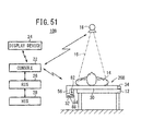
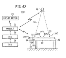
- a radiographic image capturing system 10A includes a radiation source 18 for applying radiation 16, which has a dose according to image capturing conditions, to a subject 14 such as a patient lying on an image capturing base 12 such as a bed or the like, an electronic cassette 20A for detecting radiation 16 that has passed through the subject 14 and converting the detected radiation into a radiographic image, a console 22 for controlling the radiation source 18 and the electronic cassette 20A, and a display device 24 for displaying captured radiographic images.
- the console 22, the radiation source 18, the electronic cassette 20A, and the display device 24 send signals to each other and receive signals from each other by way of a wireless LAN (Local Area Network) according to standards such as UWB (Ultra-Wide Band), IEEE802.11.a/g/n., or the like, or via wireless communications using milliwaves.
- the console 22, the radiation source 18, the electronic cassette 20A, and the display device 24 may also send signals to each other and receive signals from each other by way of wired communications using cables.
- the console 22 is connected to a radiology information system (RIS) 26, which generally manages radiographic image information handled by the radiological department of a hospital, along with other information.
- RIS radiology information system
- HIS hospital information system
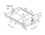
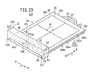
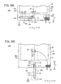
- the electronic cassette 20A which serves as the radiographic image capturing apparatus according to the first embodiment, is a portable electronic cassette, including a panel unit 30 disposed between the image capturing base 12 and the subject 14, a controller 32 disposed on the panel unit 30, and a grip 34 disposed on a side of the panel unit 30.
- the panel unit 30 is thinner than the controller 32.
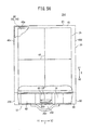
- the panel unit 30 includes a substantially rectangular housing (first housing) 40 made of a material permeable to radiation 16.
- the housing 40 has an upper surface on which the subject 14 lies, and which serves as an irradiation surface 42 that is irradiated with radiation 16.
- the irradiation surface 42 includes guide lines 44, disposed substantially centrally thereon, indicative of an image capturing area and an image capturing position for the subject 14.
- the guide lines 44 include an outer frame representing an image capturing area 36 on the irradiation surface 42, which indicates an irradiation field that is irradiated with radiation 16.
- the guide lines 44 have a central position (where two guide lines 44 cross each other in a crisscross pattern), which defines a central position of the image capturing area 36 and a geometrically central position of the electronic cassette 20A.
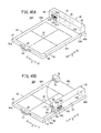
- the housing 40 has a guide 48 in the form of a straight recess or groove on a side surface (other side surface) 46c outside of the image capturing area 36 on the irradiation surface 42.
- the guide 48 extends along the directions of the arrow X (i.e., in directions parallel to side surfaces 46c, 46d).
- the housing 40 also has a guide 50 on a side surface (other side surface) 46d outside of the image capturing area 36.
- the guide 50 extends along the directions of the arrow X parallel to the guide 48.
- the straight guides 48, 50 extend parallel to each other in sandwiching relation to the image capturing area 36 formed between two side surfaces 46a, 46b (i.e., between two sides of the irradiation surface 42).
- the grip 34 is disposed on the side surface (other side surface) 46a of the housing 40.
- the grip 34 includes a handle, which cooperates with the side surface 46a in defining a hole 52 therebetween, such that the hole 52 is large enough for the hand of a doctor or radiological technician (user) to be placed therein.
- the housing 40 includes a block 54 that projects upwardly from the side surface (one side surface) 46b of the irradiation surface 42.
- the controller 32 is disposed on the side surface 46b of the irradiation surface 42 so as to cover the block 54 from above.
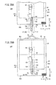
- the controller 32 includes a substantially rectangular housing (second housing) 60 made of a material permeable to radiation 16.
- the housing 60 extends in the directions of the arrow Y (i.e., in directions parallel to the side surfaces 46a, 46b) so as to cover portions of the guides 48, 50 that lie in the direction indicated by the arrow X2 (near the side surface 46b) (see FIG. 5 ).
- the housing 60 houses therein a connector 64 for fitting engagement with another connector (connector) 62 disposed on a side surface of the block 54, which faces in the direction indicated by the arrow X1, a cassette controller (panel controller) 66 electrically connected to the connector 64, for controlling the panel unit 30 through the connectors 62, 64, a power supply 68 such as a battery or the like, and a communication unit 70 for sending signals to and receiving signals from the console 22 via a wireless communication link.
- a connector 64 for fitting engagement with another connector (connector) 62 disposed on a side surface of the block 54, which faces in the direction indicated by the arrow X1
- a cassette controller (panel controller) 66 electrically connected to the connector 64, for controlling the panel unit 30 through the connectors 62, 64
- a power supply 68 such as a battery or the like
- a communication unit 70 for sending signals to and receiving signals from the console 22 via a wireless communication link.
- the power supply 68 supplies electric power to the panel unit 30 through the connectors 62, 64, and also supplies electric power to the cassette controller 66 and to the communication unit 70. If the connectors 62, 64 are separated from each other, thereby electrically disconnecting the panel unit 30 and the controller 32 from each other, the power supply 68 supplies electric power only to the cassette controller 66.
- the controller 32 has a side surface 80 facing in the direction indicated by the arrow Y2 (near the side surface 46d).
- the side surface 80 has an input terminal 82 for an AC adapter for enabling charging of the power supply 68 from an external power supply, a USB (Universal Serial Bus) terminal 84, which serves as an interface means for sending information to and receiving information from an external apparatus, and a card slot 88 for receiving a memory card 86 therein such as a PC card or the like.
- USB Universal Serial Bus
- the panel unit 30 houses therein a grid 90 for removing scattered rays of radiation 16 from the subject 14 while the radiation source 18 irradiates the subject 14 with radiation 16, a radiation conversion panel 92 for detecting radiation 16 that has passed through the subject 14, and a lead plate 94 for absorbing back scattered rays of the radiation 16.
- the grid 90, the radiation conversion panel 92, and the lead plate 94 are successively arranged in this order from the irradiation surface 42, which faces toward the subject 14.
- the radiation conversion panel 92 and the lead plate 94 are substantially coexistent with the image capturing area 36 as viewed in plan (see FIG. 5 ).
- the irradiation surface 42 may be constructed as the grid 90.
- the radiation conversion panel 92 may be an indirect-conversion-type radiation conversion panel, which employs a scintillator for converting radiation 16 that has passed through the subject 14 into visible light, and a solid-state detector (hereinafter also referred to as "pixels") made of a material such as amorphous silicon (a-Si) or the like for converting the visible light into electric signals.
- the radiation conversion panel 92 may be a direct-conversion-type radiation conversion panel, which employs a solid-state detector made of a material such as amorphous selenium (a-Se) or the like for converting the dose of radiation 16 directly into electric signals.
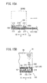
- Indirect-conversion-type conversion panels which convert radiation 16 that has passed through the subject 14 into visible light with a scintillator made of cesium iodide (CsI) or gadolinium oxide sulfur (GOS), and convert the visible light into electric signals with a solid-state detector (pixels), include a face-side readout radiation detector and a reverse readout radiation detector.
- the face-side readout radiation detector which is of an ISS (Irradiation Side Sampling) type, includes the solid-state detector and the scintillator, which are arranged successively along the direction in which radiation 16 is applied.
- the reverse readout radiation detector which is of a PSS (Penetration Side Sampling) type, includes the scintillator and the solid-state detector, which are arranged successively along the direction in which radiation 16 is applied.
- the radiation conversion panel 92 is electrically connected through a flexible board 96 to a driver circuit 98, which is electrically connected through another flexible board 100 to the connector 62.
- the housing 60 has a recess 110 defined in a side thereof facing in the direction of the arrow X2, and the connector 64 is disposed in the recess 110.
- the cassette controller 66 is electrically connected to the driver circuit 98 through the connectors 64, 62 and the flexible board 100.
- the driver circuit 98 drives the radiation conversion panel 92 in accordance with control signals (address signals) from the cassette controller 66, and reads a radiographic image from the radiation conversion panel 92, and outputs the radiographic image to the cassette controller 66.
- the power supply 68 supplies electric power to the driver circuit 98 through the connectors 64, 62 and the flexible board 100, thereby enabling the driver circuit 98 to drive the radiation conversion panel 92 through the flexible board 96.
- the driver circuit 98 is illustrated as being disposed in a region of the panel unit 30 that is displaced in the direction of the arrow X2.
- the panel unit 30 actually houses other driver circuits arranged along the guides 48, 50, in the description of the first embodiment, such other driver circuits are omitted from illustration for the sake of brevity.
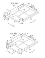
- the bottoms of the guides 48, 50 which extend in the directions of the arrow X, define respective chambers 120, 122, which are wider than upper portions of the guides 48, 50 in communication with the exterior.
- the guide 48 includes a moving member 128 comprising a slider 124 disposed in the chamber 120, and a joint 126 coupling the slider 124 and the housing 60 through the guide 48.
- the guide 50 includes a moving member 134 comprising a slider 130 disposed in the chamber 122, and a joint 132 coupling the slider 130 and the housing 60 through the guide 50.
- the sliders 124, 130 have respective widths along the directions of the arrow Y, which are essentially the same as the widths of the chambers 120, 122 along the directions of the arrow Y.
- the sliders 124, 130 have upper surfaces, which are lower than the ceilings of the chambers 120, 122. Therefore, the chambers 120, 122 include clearances that enable the sliders 124, 130 to move vertically therein.
- the sliders 124, 130 and the joints 126, 132 have respective lengths along the directions of the arrow X, which are essentially the same as each other but slightly smaller than the width of the housing 60 along the directions of the arrow X.
- the sliders 124, 130 have round opposite ends along the directions of the arrow X.
- the bottoms of the chambers 120, 122 have a plurality of chevron-shaped ridges (stop members) 140a through 140d spaced along the directions of the arrow X.
- the interval between the side surface 46a and the ridge 140a, the interval between the ridge 140b and the ridge 140c, and the interval between the ridge 140d and the side surface 46b are essentially of the same length as the lengths of the sliders 124, 130 and the joints 126, 132 along the directions of the arrow X.
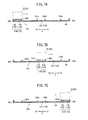
- the moving members 128, 134 are joined to the bottom surface of the housing 60 of the controller 32, and are disposed in the guides 48, 50 while the housing 60 is translated along the directions of the arrow X, as shown in FIGS. 7A through 8B , the moving members 128, 134 slide in unison with the housing 60 along the directions of the arrow X while being guided by the guides 48, 50.
- the ridges 140a through 140d are disposed in the chambers 120, 122 of the guides 48, 50, since clearances are defined between the upper surfaces of the sliders 124, 130 and the ceilings of the chambers 120, 122 (see FIG.
- the moving members 128, 134 and the guides 48, 50 jointly make up moving mechanisms 136 for translating the controller 32 with respect to the panel unit 30 along the directions of the arrow X.
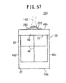
- the housing 60 of the controller 32 is positioned on the side surface 46b, as shown in FIGS. 3 and 7A . If the sliders 124, 130 are stopped between the ridge 140b and the ridge 140c, the housing 60 is positioned substantially centrally in the image capturing area 36, as shown in FIGS. 7B and 8A . If the sliders 124, 130 are stopped between the ridge 140a and the side surface 46a, the housing 60 is positioned on the side surface 46a and the grip 34, as shown in FIGS. 7C and 8B .
- the connectors 62, 64 are held in fitting engagement with each other.
- the connectors 62, 64 are brought out of fitting engagement with each other, thereby electrically disconnecting the controller 32 and the panel unit 30 from each other.
- FIGS. 9A through 9C illustrate the manner in which a user 142, such as a doctor or radiological technician, carries the electronic cassette 20A.
- the user 142 grips the grip 34 and carries the electronic cassette 20A with the controller 32 positioned on the side surface 46b (see FIG. 3 ), and with the controller 32 in a lowermost position and the grip 34 in an uppermost position.
- the power supply 68 (see FIGS. 3 and 5 ) is relatively heavy, such that the ratio of the weight of the controller 32 to the overall weight of the electronic cassette 20A is large.
- the controller 32 the cassette controller 66, the power supply 68, and the communication unit 70 are located centrally in a central region of the housing 60.
- the electronic cassette 20A is illustrated in an eccentric state, in which the geometrically central position of the electronic cassette 20A (the central position of the image capturing area 36) and the center of gravity of the electronic cassette 20A (the position near the controller 32) do not coincide with each other, thereby making the entire electronic cassette 20A unbalanced in terms of the weight distribution thereof.
- the user 142 carries the electronic cassette 20A with the controller 32 in a lowermost position, so as to lower the center of gravity of the electronic cassette 20A. Therefore, despite the unbalanced weight distribution, the user 142 can carry the electronic cassette 20A in a stable manner.
- the user 142 grips the grip 34 and carries the electronic cassette 20A while the controller 32 is disposed substantially centrally in the image capturing area 36, and the grip 34 is located in an uppermost position. Since the geometrically central position of the electronic cassette 20A and the center of gravity of the electronic cassette 20A coincide substantially with each other, an eccentric state is eliminated, thereby making the entire electronic cassette 20A balanced in terms of the weight distribution thereof. As a result, the user 142 can carry the electronic cassette 20A in a stable manner.
- the user 142 grips the grip 34 and carries the electronic cassette 20A while the controller 32 is disposed on the side surface 46a, and the controller 32 and the grip 34 are located in an uppermost position.
- the electronic cassette 20A also is in an eccentric state in which the geometrically central position of the electronic cassette 20A and the center of gravity of the electronic cassette 20A do not coincide with each other, thereby making the entire electronic cassette 20A unbalanced in terms of the weight distribution thereof.
- the center of gravity of the electronic cassette 20A is in an upper position, the user 142 can grip the heavy controller 32 through the grip 34 and can carry the electronic cassette 20A in a stable manner.
- the housing 60 can be positioned on the side surface 46b, substantially centrally within the image capturing area 36, and at the grip 34 and the side surface 46a, the user 142 can reliably carry the electronic cassette 20A if the controller 32 is disposed with respect to the panel unit 30 in any of the positions shown in FIGS. 9A through 9C .
- the radiation conversion panel 92 includes a number of pixels 150 arrayed on a substrate (not shown), a number of gate lines 152 arrayed on the substrate for supplying control signals to the pixels 150 from the driver circuit 98 through the flexible board 96, and a number of signal lines 154 arrayed on the substrate for reading electric signals output from the pixels 150, and outputting the electric signals to the driver circuit 98 through the flexible board 96.
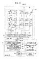
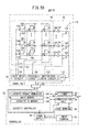
- a circuit and block arrangement of the electronic cassette 20A, which incorporates an indirect-conversion-type radiation conversion panel 92, will be described in detail below with reference to FIG. 11 .
- the radiation conversion panel 92 comprises an array of TFTs 156 arranged in rows and columns, and a photoelectric conversion layer including the pixels 150 made of a material such as a-Si or the like for converting visible light into electric signals, the photoelectric conversion layer being disposed on the array of TFTs 156.
- the pixels 150 which are supplied with a bias voltage from a biasing circuit 160 of the driver circuit 98, store electric charges generated in a case where visible light is converted into electric signals (analog signals). The electric charges can be read as image signals if the TFTs 156 are successively turned on along each of the columns.
- Gate lines 152 are connected to the TFTs 156, which are connected respectively to the pixels 150.
- the gate lines 152 extend parallel to the columns, and signal lines 154 extend parallel to the rows.
- the gate lines 152 are connected to a gate drive circuit 158, and the signal lines 154 are connected to a multiplexer 170.
- the gate lines 152 are supplied with control signals from the gate drive circuit 158 for turning on and off the TFTs 156 arranged along the columns.
- the gate drive circuit 158 is supplied with address signals from the cassette controller 66.
- Electric charges held by the pixels 150 flow into the signal lines 154 through the TFTs 156 arranged along the rows.
- the electric charges are amplified by amplifiers 164, which are connected through sample and hold circuits 166 to the multiplexer 170.
- the multiplexer 170 includes FET (Field Effect Transistor) switches 168 for switching between the signal lines 154, and a multiplexer drive circuit 162 for outputting selection signals to select one of the FET switches 168 at a time.
- the multiplexer drive circuit 162 is supplied with address signals from the cassette controller 66.
- the FET switches 168 are connected to an A/D converter 172, which supplies digital signals representing a radiographic image to the cassette controller 66.
- the TFTs 156 which function as switching elements, may be combined with any of various other image capturing devices such as a CMOS (Complementary Metal-Oxide Semiconductor) image sensor, or may be replaced with a CCD (Charge-Coupled Device) image sensor in which electric charges are shifted and transferred by shift pulses that correspond to gate signals used in the TFTs 156.
- CMOS Complementary Metal-Oxide Semiconductor
- CCD Charge-Coupled Device
- the cassette controller 66 includes an address signal generator 180, an image memory 182, a cassette ID memory 184, and a connected state detector (connection detector) 186.
- the address signal generator 180 supplies address signals to the gate drive circuit 158 and the multiplexer drive circuit 162.
- the image memory 182 stores the radiographic image detected by the radiation conversion panel 92.
- the cassette ID memory 184 stores cassette information for identifying the electronic cassette 20A.
- the connected state detector 186 detects whether or not the connectors 62, 64 are electrically connected to each other, and based on the detection result, controls supply of electric power from the power supply 68 to various components in the electronic cassette 20A.
- the radiographic image capturing system 10A which incorporates the electronic cassette 20A according to the first embodiment, basically is constructed as described above. Operations of the radiographic image capturing system 10A will be described below with reference to the flowchart shown in FIG. 12 .
- the electronic cassette 20A shown in FIG. 9B After the electronic cassette 20A shown in FIG. 9B has been carried to the image capturing base 12, the electronic cassette 20A is placed in the state shown in FIG. 1 and captures a radiographic image of the subject 14, after which the electronic cassette 20A is restored to the state shown in FIG. 9B and carried.
- step S1 shown in FIG. 12 the user 142, who may be a doctor or radiological technician, grips the grip 34 with the grip 34 being in an uppermost position and the controller 32 being located substantially centrally in the image capturing area 36 (see FIG. 9B ).
- the user carries the electronic cassette 20A from a given storage location in the radiological department of the hospital to the image capturing base 12 (see FIG. 1 ). Since the connector 62 and the connector 64 are not held in fitting engagement with each other, the connected state detector 186 (see FIG. 11 ) detects that the connector 62 and the connector 64 are electrically disconnected from each other, and controls the power supply 68 to supply electric power only to the cassette controller 66.
- the electronic cassette 20A is thus placed in a sleep mode with only the cassette controller 66 operating.
- step S2 the user 142 places the electronic cassette 20A on the image capturing base 12, with the controller 32 and the irradiation surface 42 facing upwardly. Thereafter, the user 142 translates the housing 60 of the controller 32 from the substantially central position in the image capturing area 36 (see FIGS. 7B and 8A ) to the position on the side surface 46b (see FIGS. 1 through 5 and 7A ).
- the moving members 128, 134 which are coupled to the controller 32, slide (are translated) in unison with the housing 60 in the direction of the arrow X2 while being guided by the guides 48, 50. Ends of the sliders 124, 130, which face in the direction of the arrow X2, abut against the ridges 140c, respectively. Since clearances are defined between upper surfaces of the sliders 124, 130 and the ceilings of the chambers 120, 122 of the guides 48, 50 (see FIG. 6 ), the sliders 124, 130 move over the ridges 140c and slide in the direction of the arrow X2.
- the moving members 128, 134 slide in unison with the housing 60 in the direction of the arrow X2. Even if the sliders 124, 130 abut respectively against the ridges 140d, the sliders 124, 130 move over the ridges 140d and slide in the direction of the arrow X2.
- the ends of the sliders 124, 130 which face in the direction of the arrow X2, abut against the side surface 46b, whereupon the sliders 124, 130 are positioned between the side surface 46b and the ridge 140d.
- the housing 60 of the controller 32 which is coupled to the moving members 128, 134, is positioned on the side surface 46b, and the connector 62 of the block 54 and the connector 64 in the recess 110 are held in fitting engagement with each other.
- the connected state detector 186 controls the power supply 68 to supply electric power to the communication unit 70 and the panel unit 30, in addition to the cassette controller 66.
- the power supply 68 begins supplying electric power to the communication unit 70 and the panel unit 30.
- the communication unit 70 is capable of sending signals to and receiving signals from the console 22 via a wireless communication link.
- the driver circuit 98 of the panel unit 30 becomes activated.
- the biasing circuit 160 supplies a bias voltage to the pixels 150, thus enabling the pixels 150 to store electric charges therein.
- the electronic cassette 20A changes from a sleep mode into an active mode.
- step S3 the user 142 performs a preparatory action to capture a radiographic image of a region to be imaged of the subject 14.
- the user 142 operates the console 22 to register image capturing conditions (e.g., a tube voltage and a tube current of the radiation source 18, an exposure time of the radiation 16, etc.) concerning subject information of the subject 14 to be imaged. If a region to be imaged and an imaging method are determined in advance, then the user 142 may also register such image capturing conditions.
- image capturing conditions e.g., a tube voltage and a tube current of the radiation source 18, an exposure time of the radiation 16, etc.
- the user 142 adjusts the imaging distance between the radiation source 18 and the radiation conversion panel 92 to an SID (source-to-image distance).
- the user 142 places the subject 14 on the irradiation surface 42, and positions the subject 14 such that the region to be imaged of the subject 14 enters within the image capturing area 36, such that the central position of the region to be imaged is substantially aligned with the central position of the image capturing area 36.
- step S4 after the preparatory process has been performed, the user 142 presses an exposure switch (not shown) located on the console 22 or on the radiation source 18. If the exposure switch is located on the console 22, then after the exposure switch is pressed, the console 22 sends image capturing conditions to the radiation source 18 via a wireless communication link. If the exposure switch is located on the radiation source 18, then after the exposure switch is pressed, the radiation source 18 requests the console 22 to send the image capturing conditions via a wireless communication link, whereupon the console 22 sends the image capturing conditions to the radiation source 18 via the wireless communication link in response to the request from the radiation source 18.
- the radiation source 18 Upon receiving the image capturing conditions, the radiation source 18 applies a prescribed dose of radiation 16 to the subject 14 for a preset period of time according to the image capturing conditions. Radiation 16 passes through the subject 14 to the radiation conversion panel 92 in the panel unit 30.
- step S5 if the radiation conversion panel 92 is an indirect-conversion-type radiation conversion panel, then the scintillator emits visible light having an intensity depending on the intensity of the radiation 16.
- the pixels 150 of the photoelectric conversion layer convert the visible light into electric signals, and store the electric signals as electric charges. Electric charges stored in the pixels 150, which represent a radiographic image of the subject 14, are read from the pixels 150 according to address signals, which are supplied from the address signal generator 180 of the cassette controller 66 to the gate drive circuit 158 and the multiplexer drive circuit 162.
- the gate drive circuit 158 supplies control signals to gates of the TFTs 156 connected to the gate lines 152, which correspond to the address signals supplied from the address signal generator 180.
- the multiplexer drive circuit 162 outputs selection signals according to address signals supplied from the address signal generator 180 in order to successively switch between (successively turn on and off) the FET switches 168 and to successively read, through the signal lines 154, the radiographic image as electric charges stored in the pixels 150, which are connected to the gate lines 152 selected by the gate drive circuit 158.
- the radiographic image read from the pixels 150 connected to the selected gate lines 152 is amplified by the amplifiers 164, sampled by the sample and hold circuits 166, and supplied through the FET switches 168 to the A/D converter 172, which converts the radiographic image into digital signals.
- the radiographic image, which is converted into digital signals, is stored in the image memory 182 of the cassette controller 66 (step S6).
- the gate drive circuit 158 successively switches between the gate lines 152 that output control signals according to address signals supplied from the address signal generator 180, reads the radiographic image as electric charges stored in the pixels 150 connected to the gate lines 152, and stores the radiographic image in the image memory 182 of the cassette controller 66 through the FET switches 168 and the A/D converter 172 (step S6).
- the radiographic image which is stored in the image memory 182, is sent together with the cassette ID information stored in the cassette ID memory 184 through the communication unit 70 to the console 22 via a wireless communication link.
- the console 22 performs a prescribed image processing routine on the received radiographic image, and sends the processed radiographic image to the display device 24 via a wireless communication link.
- the display device 24 then displays the received radiographic image (step S7).
- the user 142 views the radiographic image displayed on the display device 24 and confirms that the radiographic image of the subject 14 has appropriately been obtained.
- step S8 after the image capturing process on the subject 14 has been completed, the user 142 translates the housing 60 of the controller 32 from its present position on the side surface 46b (see FIGS. 1 through 5 and 7A ) to a position located substantially centrally within the image capturing area 36 (see FIGS. 7B and 8A ).
- the user 142 pushes the housing 60 in the direction of the arrow X1 in order to slide (translate) the moving members 128, 134 coupled to the controller 32 in unison with the housing 60 in the direction of the arrow X1 while the moving members 128, 134 are guided by the guides 48, 50.
- the connected state detector 186 Upon the connected state detector 186 detecting that the connector 62 and the connector 64 are electrically disconnected from each other, the connected state detector 186 controls the power supply 68 in order to supply electric power only to the cassette controller 66.
- the power supply 68 immediately stops supplying electric power to the communication unit 70 and the panel unit 30, and supplies electric power only to the cassette controller 66.
- the electronic cassette 20A changes from the active mode into the sleep mode in which only the cassette controller 66 is operable.
- the user 142 pushes the housing 60 further in the direction of the arrow X1.
- the moving members 128, 134 are translated in unison with the housing 60 in the direction of the arrow X1.
- the sliders 124, 130 abut against and move over the ridges 140c, and are further translated in the direction of the arrow X1.
- step S9 the user 142 grips the grip 34 with the grip 34 being located in the uppermost position, and the controller 32 being positioned substantially centrally in the image capturing area 36.
- the user carries the electronic cassette 20A to a given storage location in the radiological department of the hospital.
- steps S1 and S9 shown in FIG. 12 if the user 142 carries the electronic cassette 20A as shown in FIG. 9C , then in step S2, the user 142 may translate the controller 32 from the grip 34 and the side surface 46a to the side surface 46b, and in step S8, the user 142 may translate the controller 32 from the side surface 46b to the grip 34 and the side surface 46a.
- steps S1 and S9 shown in FIG. 12 if the user 142 carries the electronic cassette 20A as shown in FIG. 9A , then the operations performed in steps S2 and S8 are dispensed with.
- the center of gravity of the electronic cassette 20A according to the first embodiment can be changed easily by translating the controller 32, which is responsible for unbalanced weight distribution, with respect to the panel unit 30 along the directions of the arrow X, using the moving mechanisms 136, which include the guides 48, 50 and the moving members 128, 134.
- the ratio of the weight of the controller 32 to the overall weight of the electronic cassette 20A is relatively large, if the controller 32 is displaced with respect to the geometrically central position of the electronic cassette 20A (a substantially central position of the image capturing area 36), then the electronic cassette 20A is in an eccentric state in which the center of gravity thereof does not coincide with the above central position, thereby making the entire electronic cassette 20A unbalanced in terms of the weight distribution thereof.
- the controller 32 is translated with respect to the panel unit 30 along the directions of the arrow X, so as to bring the central position and the center of gravity into substantial agreement with each other, thereby easily eliminating the unbalanced weight distribution.
- the user 142 carries the electronic cassette 20A with the grip 34 in an uppermost position, as shown in FIG. 9B .
- the user 142 finds it easy to carry the electronic cassette 20A in a stable manner. As a result, the user 142 can carry the electronic cassette 20A without dropping the electronic cassette 20A or causing the controller 32 to hit other objects, and the user experiences a reduced burden upon carrying the electronic cassette 20A.
- the user 142 can carry the electronic cassette 20A in a stable manner.
- the controller 32 Since the moving members 128, 134 and the controller 32 are linearly translated in unison with each other along the guides 48, 50 in the directions of the arrow X, the controller 32 is translated with respect to the panel unit 30 by a simple mechanism. Even though the controller 32 may be disposed over the image capturing area 36 while the electronic cassette 20A is being carried, the controller 32 can be retracted away from the image capturing area 36 in the image capturing process. Therefore, the controller 32 and the guides 48, 50 do not present an obstacle to capturing of radiographic images.
- the guides 48, 50 extend along the directions of the arrow X (the longitudinal direction of the housing 40), which is substantially perpendicular to two sides (two side surfaces 46a, 46b) of the irradiation surface 42. Consequently, in the case that the moving members 128, 134 and the controller 32 are linearly translated in unison with each other, the central position and the aforementioned center of gravity can easily be made to coincide with each other, thereby reliably eliminating any unbalanced weight distribution.
- the two moving members 128, 134 are mounted on the controller 32 while being disposed in the two guides 48, 50. As a result, the controller 32 and the two moving members 128, 134 can be translated more stably and reliably along the two guides 48, 50.
- the guides 48, 50 are in the form of recesses or grooves, which are defined substantially linearly in the irradiation surface 42 of the housing 40.
- the moving members 128, 134 are slidable linearly along such recesses or grooves. Therefore, the controller 32 can be translated simply and reliably with respect to the panel unit 30.
- the ridges 140a through 140d which serve to stop sliding movement of the moving members 128, 134, are disposed in the chambers 120, 122 of the guides 48, 50 in the form of recesses or grooves. Accordingly, the controller 32 can be stopped reliably at any desired position with respect to the panel unit 30.
- the user 142 finds it easy to carry the electronic cassette 20A.
- the power supply 68 stops supplying electric power to the communication unit 70 and the panel unit 30. Therefore, wasteful electric power consumption is minimized.
- the connector 62 and the connector 64 are brought out of fitting engagement with each other, thereby electrically disconnecting the panel unit 30 and the controller 32 from each other.
- the power supply 68 stops supplying electric power to the communication unit 70 and the panel unit 30.
- the cassette controller 66 includes the connected state detector 186, which detects whether or not the connectors 62, 64 are electrically connected to each other. As the connected state detector 186 detects whether or not the connectors 62, 64 are electrically connected to each other, the timing to control the panel unit 30 and the timing to read radiographic images from the radiation conversion panel 92 can easily be grasped. The connected state detector 186 indicates the detection result to the power supply 68, so as to enable the power supply 68 to supply electric power efficiently.
- the thickness of the panel unit 30 is less than the thickness of the controller 32, thereby making the electronic cassette 20A both thin and lightweight.
- the controller 32 can be translated with respect to the panel unit 30 along the directions of the arrow X, after the controller 32 has been moved to the position shown in FIGS. 3 and 7A with respect to the panel unit 30 using the moving mechanisms 136, which include the guides 48, 50 and the moving members 128, 134, the user 142 can carry the electronic cassette 20A with the grip 34 located in an uppermost position, and with the controller 32 located in a lowermost position, as shown in FIG. 9A .
- the electronic cassette 20A has an unbalanced weight distribution, since the user 142 carries the electronic cassette 20A with the center of gravity kept low, the user 142 can carry the electronic cassette 20A in a stable manner.
- the electronic cassette 20A feels light to the user 142 upon carrying the same. Therefore, the user 142 can carry the electronic cassette 20A easily and in a stable manner. Consequently, as shown in FIG. 9A , the user 142 can carry the electronic cassette 20A without dropping the electronic cassette 20A or causing the controller 32 to hit other objects, and thus, the user experiences a reduced burden upon carrying the electronic cassette 20A.
- the user can carry the electronic cassette 20A with the grip 34 and the controller 32 in an uppermost position, as shown in FIG. 9C .
- the electronic cassette 20A has an unbalanced weight distribution, since the user 142 grips the heavy controller 32 through the grip 34, the user 142 can carry the electronic cassette 20A in a stable manner.
- the electronic cassette 20A feels light to the user 142 upon carrying the same, and thus the user 142 finds it easy to carry the electronic cassette 20A in a stable manner.
- the user 142 can carry the electronic cassette 20A without dropping the electronic cassette 20A or causing the controller 32 to hit other objects, and thus, the user experiences a reduced burden upon carrying the electronic cassette 20A.
- the housing 60 of the controller 32 which is thicker than the housing 40 of the panel unit 30, is disposed on the housing 40.
- the first embodiment is not limited to this description, and the controller 32 may be disposed so as to protrude from the housing 40, insofar as the controller 32 can still be translated with respect to the panel unit 30.
- the controller 32 is disposed at a location outside of the image capturing area 36 of the panel unit 30 at least during the image capturing process.
- the first embodiment is not limited to the above description, and the controller 32 may be disposed at a location outside of an area of the panel unit 30 that is irradiated with radiation 16 having passed through the subject 14.
- the controller 32 may be disposed at a location within the image capturing area 36 that is not irradiated with radiation 16.
- the console 22 trims a portion of the radiographic image acquired from the electronic cassette 20A, which corresponds to the area irradiated with radiation 16, thereby obtaining a desired image that corresponds to the small area.
- the electronic cassette 20A according to the first embodiment is not limited to the above description, but may be implemented according to the embodiments shown in FIGS. 13 through 26 .
- FIG. 13 is a perspective view showing a process of charging the power supply 68 using a cradle 190, which is disposed in a necessary location in a medical organization.
- the electronic cassette 20A and the cradle 190 are electrically connected to each other through a USB cable 192 having connectors 194, 196.
- the cradle 190 may be used not only for charging the power supply 68, but also to send required information to and receive required information from the console 22 and the RIS 26 in the medical organization, using a wireless communication or a wired communication function of the cradle 190.
- Information that is sent and received includes radiographic images recorded in the image memory 182 of the electronic cassette 20A.
- the cradle 190 has a display unit 198, which may display the charged state of the electronic cassette 20A together with other necessary information including radiographic images acquired from the electronic cassette 20A.
- a plurality of cradles 190 may be connected to a network. Charged states of electronic cassettes 20A connected to the respective cradles 190 may be collected through the network, whereby locations of electronic cassettes 20A, which have been charged to an operational state, can be confirmed.
- FIG. 14A shows the housing 60 of the controller 32, which is covered entirely with a cushioning member 200.
- FIG. 14B shows the housing 60, a side surface 46b of which is covered with a cushioning member 202.
- the controller 32 is disposed in a lowermost position on the electronic cassette 20A, as shown in FIG. 9A .
- the housing 60 of the controller 32 is covered entirely with the cushioning member 200, or partially by means of the cushioning member 202, whereby the controller 32 is effectively protected from impacts that may occur if the controller 32 hits other objects, or if the electronic cassette 20A is dropped.
- FIGS. 15A and 15B show the manner in which the controller 32 is translated along the directions of the arrow X by moving members 208 including wheels 210, rather than the moving members 128, 134 shown in FIGS. 6 through 7C .
- the moving mechanisms 136 are made up of the moving members 208 and the guides 48, 50.
- Each of the moving members 208 which are disposed in the respective guides 48, 50, has four wheels 210 that travel on bottoms of the chambers 120, 122, a carriage 214 that extends in the directions of the arrow X and through which axles 212 of the four wheels 210 extend, and a joint 216 coupling the carriage 214 and the housing 60 of the controller 32 to each other.
- the entire length of each of the moving members 208 along the directions of the arrow X (the distance from the wheels 210 that face in the direction of the arrow X1 to the wheels 210 that face in the direction of the arrow X2) is essentially the same as the interval between the side surface 46b and the ridge 140d. Clearances, which are large enough for the wheels 210 to move vertically therein, are defined between the wheels 210 and the ceilings of the chambers 120, 122.
- FIGS. 15A and 15B similar to the case of the moving members 128, 134, if the housing 60 is translated along the directions of the arrow X, the moving members 208 travel in unison with the housing 60 in the directions of the arrow X while being guided by the guides 48, 50. Since the moving members 208 travel upon rotation of the wheels 210, it is possible to easily and reliably translate the controller 32 with respect to the panel unit 30 along the directions of the arrow X.
- the moving members 208 can travel over the ridges 140a through 140d along the directions of the arrow X.
- FIGS. 16 through 18B show guides 220, 222 in the side surfaces 46c, 46d.
- the guides 220, 222 extend parallel to each other along the directions of the arrow X between the side surface 46a and the side surface 46b.
- the housing 60 of the controller 32 has a ledge 226 on a side surface 80 thereof, which extends downward along the side surface 46d, and a ledge 224 on another side surface 80 thereof, which extends downward along the side surface 46c.
- the ledges 224, 226 are disposed in covering relation to portions of the guides 220, 222 proximate the side surface 46b (see FIGS. 16 and 17 ).
- the guides 220, 222 have portions near the radiation conversion panel 92, which define respective chambers 230, 232 that are vertically wider than inlet portions of the guides 220, 222 in communication with the exterior.
- Moving members 238, 244 which are substantially identical in shape to the moving members 128, 134 (see FIGS. 6 through 7C ), or moving members 258, 264, which are capable of traveling on wheels 254, 260 similar to the moving members 208 (see FIGS. 15A and 15B ), are coupled to the ledges 224, 226 of the housing 60 and are disposed in the guides 220, 222.
- the moving mechanisms 136 are made up of the moving members 238, 244, 258, 264 and the guides 220, 222.
- the moving members 238, 244 have respective sliders 234, 240, which are disposed in the chambers 230, 232, and respective joints 236, 242 that join the sliders 234, 240 and the ledges 224, 226.
- the moving members 258, 264 have two respective wheels 254, 260 disposed in the chambers 230, 232, and respective axles 256, 262 that couple the wheels 254, 260 and the ledges 224, 226.
- the moving members 238, 244, 258, 264 have total lengths along the directions of the arrow X, which are substantially the same as the interval between the side surface 46b and a ridge 270. Clearances, which are large enough for the sliders 234, 240 and the wheels 254, 260 to move vertically therein, are defined between the sliders 234, 240, the wheels 254, 260, and the ceilings of the chambers 230, 232.
- FIGS. 16 through 18B similar to the case of the moving members 128, 134 and the moving members 208, in the case that the housing 60 is translated along the directions of the arrow X, the moving members 238, 244, 258, 264 are translated in unison with the housing 60 along the directions of the arrow X while being guided by the guides 220, 222.
- FIGS. 19A through 22 show grips disposed in locations other than the side surface 46a.
- FIG. 19A in addition to the grip 34, another grip 280 is disposed on the side surface 46b of the block 54.
- the grip 280 includes a handle that cooperates with the block 54 in defining a hole 282, which is large enough for a hand of the user 142 to be placed therein.
- the user 142 grips the grip 34 with one hand and grips the grip 280 with the other hand, whereby the user can carry the electronic cassette 20A.
- the user 142 can carry the electronic cassette 20A with a well-balanced weight distribution.
- the user 142 can carry the electronic cassette 20A with increased stability.
- the two grips 34, 280 make it possible for the user 142 to carry the electronic cassette 20A while gripping the grip 34 (see FIGS. 9A through 9C ), and while the grip 280 is in an uppermost position. Consequently, the user 142 finds it easy to handle the electronic cassette 20A while carrying the same.
- FIG. 19B in addition to the grip 34, another grip 330 is disposed on the side surface 46c.
- the grip 330 includes a handle that cooperates with the side surface 46c in defining a hole 332, which is large enough for a hand of the user 142 to be placed therein.
- the user 142 grips the grip 330, which is held in an uppermost position, and can carry the electronic cassette 20A.
- the user 142 can carry the electronic cassette 20A stably with a well-balanced weight distribution.
- the two grips 34, 330 the user 142 finds it easy to handle the electronic cassette 20A while carrying the same, in the same manner as with the arrangement shown in FIG. 19A .
- FIG. 20A in addition to the grip 34, another grip 290 is disposed on the upper surface of the housing 60 of the controller 32.
- the grip 290 includes a handle that cooperates with the upper surface of the housing 60 in defining a hole 292, which is large enough for a hand of the user 142 to be placed therein.
- the user 142 grips the grip 290, which is held in an uppermost position, and can carry the electronic cassette 20A.
- the user 142 can carry the electronic cassette 20A with a well-balanced weight distribution. Since the user 142 grips the heavy controller 32 directly through the grip 290, the electronic cassette 20A feels light while being carried by the user 142, and the user 142 finds it possible to carry the electronic cassette 20A easily and in a stable manner.
- the user 142 may do so by gripping the grip 290, and hence can easily translate the controller 32.
- the grip 290 enables the user 142 to feel comfortable in handling the electronic cassette 20A upon carrying the electronic cassette 20A and translating the controller 32.
- FIG. 20B differs from the structure shown in FIG. 20A , in that a foldable grip 300 is disposed on the upper surface of the housing 60.
- the upper surface of the housing 60 has a substantially hexagonal recess 302 defined therein, and opposite ends of the grip 300 are disposed in the recess 302.
- the recess 302 houses a rectangular support 304 therein.
- a shaft 306, which extends through the support 304, has opposite ends coupled to respective opposite ends of the grip 300.
- the grip 300 is placed in the recess 302. If the user 142 intends to grip the grip 300, the user 142 turns the central portion of the grip 300 about the shaft 306, pulls the grip 300 out of the recess 302, and grips the grip 300. For placing the grip 300 back into the recess 302, the user 142 turns the central portion of the grip 300 about the shaft 306 and inserts the grip 300 into the recess 302.
- FIG. 20B provides the same advantages offered by the structure shown in FIG. 20A .
- the grip 300 since the user 142 may pull out the grip 300 only at times that the electronic cassette 20A is carried or the controller 32 is translated, the grip 300 does not present an obstacle to capturing radiographic images. Therefore, it is easier for the user 142 to handle the electronic cassette 20A.
- FIG. 21A differs from the structure shown in FIG. 20A , in that a grip 310 is disposed on a side surface 308 of the housing 60.
- the grip 310 includes a handle that cooperates with the side surface 308 of the housing 60 in defining a hole 312, which is large enough for a hand of the user 142 to be placed therein.
- FIG. 21B differs from the structure shown in FIG. 20B , in that a foldable grip 320 is disposed on the side surface 308 of the housing 60.
- the side surface 308 of the housing 60 has a substantially hexagonal recess 322 defined therein, and the grip 320 has opposite ends disposed in the recess 322.
- the recess 322 houses a rectangular support 324 therein.
- a shaft 326 which extends through the support 324, has opposite ends coupled to respective opposite ends of the grip 320.
- FIGS. 21A and 21B offer the same advantages as the structures shown in FIGS. 20A and 20B .
- FIG. 22 shows a foldable grip 410, which is mounted on the side surface 46a of the housing 60 instead of the grip 34.
- the side surface 46a of the housing 60 has a substantially hexagonal recess 412 defined therein, and the grip 410 has opposite ends disposed in the recess 412.
- the recess 412 houses a rectangular support 414 therein.
- a shaft 416 which extends through the support 414, has opposite ends coupled to respective opposite ends of the grip 410.
- the grip 410 does not present an obstacle to capturing of radiographic images. Therefore, the user 142 finds it easier to handle the electronic cassette 20A.
- the electronic cassette 20A according to the first embodiment may incorporate further structural details as shown in FIGS. 23 and 24 .
- FIG. 23 shows rail-like guides 500, 502, which are disposed on the side surfaces 46c, 46d, respectively, instead of the guides 220, 222 described above.
- the guides 500, 502 have a plurality of chevron-shaped ridges 506a through 506d, which function the same as the aforementioned ridges 140a through 140d, 270.
- a block 504, which has the same function as the aforementioned block 54, is removably mounted on the housing 40 at the side surface 46b of the irradiation surface 42.
- the ledges 224, 226 are constructed as moving members (sliders), which are slidable along the guides 500, 502.
- FIG. 23 offers the same advantages as the guides 220, 222 and the ridges 270 described above. If the controller 32 is slid along the guides 500, 502 in the direction of the arrow X2 with the block 504 removed from the housing 40, the controller 32 can be detached from the panel unit 30. As a result, the electronic cassette 20A can easily be serviced for maintenance and replacement of parts.
- the electronic cassette 20A which includes the guides 48, 50, 220, 222 and the ridges 140a through 140d, 270, may include the block 504 instead of the block 54 to thereby provide the advantages that are offered by the block 504.
- the irradiation surface 42 is irradiated with radiation 16.
- the subject 14 may be imaged after the electronic cassette 20A has been turned upside down and placed on the image capturing base 12.
- the bottom surface of the panel unit 30 serves as an image capturing surface that is irradiated with radiation 16, and the grid 90 and the lead plate 94 may be dispensed with.
- the above modification offers the same advantages as the embodiment described above. Furthermore, since the irradiation surface 42 or the bottom surface can be selected as an image capturing surface depending on the image capturing method to be carried out on the subject 14, the electronic cassette 20A can be handled with increased ease.
- the first embodiment also is applicable to capturing of radiographic images using a light readout type radiation conversion panel.
- a light readout type radiation conversion panel operates in the following manner. In a case where radiation is applied to each solid-state detector, an electrostatic latent image, which depends on the dose of applied radiation, is stored and recorded in the solid-state detector. For reading the electrostatic latent image, the radiation conversion panel is irradiated with reading light, and the value of an electric current generated by the radiation conversion panel is acquired as a radiographic image. The radiation conversion panel may be reused after being irradiated with erasing light, to thereby erase the radiographic image, which remains as a residual electrostatic latent image (see Japanese Laid-Open Patent Publication No. 2000-105297 ).
- the entire electronic cassette 20A may be of a water-resistant and hermetically sealed structure, and the electronic cassette 20A may be sterilized and cleaned as necessary, so that a single electronic cassette 20A can be used repeatedly.
- the first embodiment is not limited to capturing of radiographic images in medical organizations, but also may be applied to capturing of images of subjects at disaster sites or in home-care service sites, or may be installed on medical checkup motor vehicles for capturing images of subjects.
- the first embodiment is not limited to use in capturing of radiographic images in the medical field, but may also be applied to capturing of radiographic images in various nondestructive tests.
- the first invention is not limited to the above embodiment, but various alternative arrangements may be adopted without departing from the scope of the first invention.
- the radiation conversion panel 92 may comprise a radiation detector 600 according to the modification shown in FIGS. 25 and 26 .
- FIG. 25 is a schematic cross-sectional view of three pixels of the radiation detector 600 according to the modification.
- the radiation detector 600 includes a signal output section 604 including switching elements, a sensor 606 including solid-state detectors, and a scintillator 608, which are successively deposited on an insulating substrate 602.
- the signal output section 604 and the sensor 606 jointly make up a pixel.
- the radiation detector 600 includes a matrix of pixels arrayed on the insulating substrate 602. In each of the pixels, the signal output section 604 is superposed on the sensor 606.
- the scintillator 608 is disposed over the sensor 606 with a transparent insulating film 610 interposed therebetween.
- the scintillator 608 is in the form of a film of phosphor, which serves to emit light converted from radiation 16. If the upper surface (remote from the substrate 602) in FIG. 25 serves as an irradiation surface 42 (see FIGS. 2 through 5 , 8A through 9C , 13 through 14B , 16 , and 19A through 23 ), then in the case that radiation 16 is applied from above, the radiation detector 600 functions as a PSS-type radiation detector, and the phosphor of the scintillator 608 emits light converted from the applied radiation 16.
- Light emitted by the scintillator 608 preferably has a visible wavelength range (from 360 nm to 830 nm). If the radiation detector 600 is used to capture a monochromatic image, then light emitted by the scintillator 608 preferably includes a green wavelength range.
- the phosphor that is used in the scintillator 608 preferably includes CsI, and more preferably, includes CsI(Tl) (thallium-added cesium iodide) which, upon being irradiated with X-rays, emits light in a wavelength spectrum ranging from 420 nm to 700 nm.
- CsI(Tl) thallium-added cesium iodide
- Light emitted from CsI(Tl) has a peak wavelength of 565 nm in the visible range.
- the scintillator 608 may be formed by depositing CsI(Tl) having a columnar crystalline structure on an evaporation base. If the scintillator 608 is formed by such an evaporation process, then the evaporation base preferably, but not necessarily, is made of Al, from the standpoints of X-ray transmittance and cost. If the scintillator 608 is made of GOS, then a resin base may be coated with GOS, which then is applied to the surface of a TFT active matrix substrate. In this manner, the TFT active matrix substrate can be saved in the event of a coating failure of the GOS.
- the sensor 606 includes an upper electrode 612, a lower electrode 614, and a photoelectric conversion film 616 disposed between the upper electrode 612 and the lower electrode 614.
- the upper electrode 612 preferably is made of an electrically conductive material, which is transparent to at least the wavelength of light emitted by the scintillator 608. More specifically, the upper electrode 612 preferably is made of a transparent conducting oxide (TCO), which exhibits a high transmittance with respect to visible light and has a small resistance value. Although the upper electrode 612 may be a thin metal film such as Au or the like, TCO is preferable because Au tends to exhibit an increased resistance value at a transmittance of 90% or higher.
- TCO transparent conducting oxide
- ITO Indium Tin Oxide
- IZO Indium Tin Oxide
- AZO Zinc Oxide
- FTO Zinc Oxide
- SnO 2 Tin Oxide
- TiO 2 TiO 2
- ZnO 2 or the like
- ITO is the most preferable from the standpoints of process simplification, low resistance, and transparency.
- the upper electrode 612 may be a single electrode that is shared by all the pixels, or the upper electrode 612 may be a plurality of electrodes assigned to respective pixels.
- the photoelectric conversion film 616 which contains an organic photoconductor (OPC), absorbs light emitted from the scintillator 608 and generates electric charges depending on the absorbed light.
- the photoelectric conversion film 616 which contains an organic photoconductor (organic photoelectric conversion material), has a sharp absorption spectrum in the range of visible light, and does not absorb electromagnetic waves apart from light emitted from the scintillator 608. Therefore, noise, which would otherwise be produced if radiation 16 were absorbed by the photoelectric conversion film 616, is effectively minimized.
- the photoelectric conversion film 616 may contain a-Si instead of an organic photoconductor.
- a photoelectric conversion film 616 containing a-Si has a wide absorption spectrum for efficiently absorbing light emitted from the scintillator 608.
- the absorption peak wavelength thereof preferably is as close as possible to the light emission peak wavelength of the scintillator 608.
- the absorption peak wavelength of the organic photoconductor and the light emission peak wavelength of the scintillator 608 should ideally be in agreement with each other, it is possible to sufficiently absorb light emitted by the scintillator 608 if the difference between the absorption peak wavelength and the light emission peak wavelength is small enough. More specifically, the difference between the absorption peak wavelength of the organic photoconductor and the light emission peak wavelength of the scintillator 608 with respect to radiation 16 preferably is 10 nm or smaller, and more preferably, 5 nm or smaller.
- Organic photoconductors that meet the above requirements include quinacridone-based organic compounds and phthalocyanine-based organic compounds. Since quinacridone has an absorption peak wavelength of 560 nm in the visible range, if quinacridone is used as the organic photoelectric conversion material and CsI(Tl) is used as the material for the scintillator 608, the difference between the above peak wavelengths can be reduced to 5 nm or less, thereby making it possible to substantially maximize the amount of electric charge generated by the photoelectric conversion film 616.
- the sensor 606 includes an organic layer formed by superposition or mixture of an electromagnetic wave absorption region, a photoelectric conversion region, an electron transport region, a hole transport region, an electron blocking region, a hole blocking region, a crystallization preventing region, an electrode, and an interlayer contact improving region, etc.
- the organic layer preferably includes an organic p-type compound (organic p-type semiconductor) or an organic n-type compound (organic n-type semiconductor).
- An organic p-type semiconductor is a donor organic semiconductor (compound) typified primarily by a hole transport organic compound, and refers to an organic compound that tends to donate electrons. More specifically, if two organic materials are used in contact with each other, one of the organic materials, which has a lower ionization potential, is referred to as a donor organic compound. Any type of electron-donating organic compound can be used as the donor organic compound.
- An organic n-type semiconductor is an acceptor organic semiconductor (compound) typified primarily by an electron transport organic compound, and refers to an organic compound that tends to accept electrons. More specifically, if two organic materials are used in contact with each other, one of the organic materials, which has a larger electron affinity, is referred to as an acceptor organic compound. Any type of electron-accepting organic compound can be used as the acceptor organic compound.
- the photoelectric conversion film 616 may contain fullerene or carbon nanotubes.
- the thickness of the photoelectric conversion film 616 should be as large as possible for the purpose of absorbing light from the scintillator 608. However, if the thickness of the photoelectric conversion film 616 is greater than a certain value, then the intensity of the electric field, which is produced on the photoelectric conversion film 616 by a bias voltage applied from opposite ends of the photoelectric conversion film 616, is reduced and electric charges cannot be collected.
- the thickness of the photoelectric conversion film 616 preferably is in the range from 30 nm to 300 nm, more preferably, in the range from 50 nm to 250 nm, and even more preferably, in the range from 80 nm to 200 nm.
- the photoelectric conversion film 616 is illustrated as being shared by all of the pixels. However, the photoelectric conversion film 616 may be divided into a plurality of films assigned to respective pixels. As illustrated, the lower electrode 614 comprises a plurality of thin films assigned to respective pixels. However, the lower electrode 614 may be a single thin film that is shared by all of the pixels.
- the lower electrode 614 may be made of a transparent or opaque electrically conductive material, preferably Al, silver, or the like. The thickness of the lower electrode 614 may be in the range from 30 nm to 300 nm.
- the sensor 606 moves one type of electric charge (holes or electrons) generated in the photoelectric conversion film 616 to the upper electrode 612, and moves the other type of electric charge to the lower electrode 614.
- an interconnection is connected to the upper electrode 612 for applying the bias voltage therethrough to the upper electrode 612.
- the bias voltage has a polarity, which is set so as to move electrons generated in the photoelectric conversion film 616 to the upper electrode 612, and to move holes to the lower electrode 614.
- the bias voltage may have an opposite polarity.
- the sensor 606 of each pixel includes at least the lower electrode 614, the photoelectric conversion film 616, and the upper electrode 612.
- the sensor 606 preferably additionally includes either an electron blocking film 618 or a hole blocking film 620, and more preferably, includes both the electron blocking film 618 and the hole blocking film 620.
- the electron blocking film 618 may be disposed between the lower electrode 614 and the photoelectric conversion film 616. In the case that a bias voltage is applied between the lower electrode 614 and the upper electrode 612, the electron blocking film 618 is capable of preventing electrons from being injected from the lower electrode 614 into the photoelectric conversion film 616, thereby preventing dark current from increasing.
- the electron blocking film 618 may be made of an electron-donating organic material.
- the electron blocking film 618 actually is made of a material selected depending on the material of the electrode and the material of the photoelectric conversion film 616, which are disposed adjacent thereto.
- a preferable material has an electron affinity (Ea), which is at least 1.3 eV greater than the work function (Wf) of the material of the adjacent electrode, and an ionization potential (Ip), which is equal to or smaller than the Ip of the material of the adjacent photoelectric conversion film 616.
- Ea electron affinity
- Wf work function
- Ip ionization potential
- the thickness of the electron blocking film 618 preferably is in the range from 10 nm to 200 nm, more preferably, in the range from 30 nm to 150 nm, and even more preferably, in the range from 50 nm to 100 nm, in order to reliably achieve a dark current reducing capability and to prevent the photoelectric conversion efficiency of the sensor 606 from being lowered.
- the hole blocking film 620 may be disposed between the photoelectric conversion film 616 and the upper electrode 612. If a bias voltage is applied between the lower electrode 614 and the upper electrode 612, the hole blocking film 620 can prevent holes from being injected from the upper electrode 612 into the photoelectric conversion film 616, thereby preventing dark current from increasing.
- the hole blocking film 620 may be made of an electron-accepting organic material.
- the thickness of the hole blocking film 620 preferably is in the range from 10 nm to 200 nm, more preferably, in the range from 30 nm to 150 nm, and even more preferably, in the range from 50 nm to 100 nm, in order to reliably achieve a dark current reducing capability and to prevent the photoelectric conversion efficiency of the sensor 606 from being lowered.
- the hole blocking film 620 actually is made of a material selected depending on the material of the electrode adjacent thereto, as well as the material of the photoelectric conversion film 616 adjacent thereto.
- a preferable material has an ionization potential (Ip) that is at least 1.3 eV greater than the work function (Wf) of the material of the adjacent electrode, and an electron affinity (Ea) equal to or greater than the Ea of the material of the adjacent photoelectric conversion film 616.
- Ip ionization potential
- Wf work function
- Ea electron affinity
- the electron blocking film 618 and the hole blocking layer 620 may be switched in position. Both of the electron blocking film 618 and the hole blocking layer 620 are not necessarily required, and either one of the electron blocking film 618 or the hole blocking layer 620 may be included to provide a certain dark current reducing capability.
- the signal output section 604 is disposed on the surface of the substrate 602 in alignment with the lower electrode 614 of each pixel, and includes a storage capacitor 622 for storing electric charges that have moved to the lower electrode 614, together with a TFT 624 for converting electric charges stored in the storage capacitor 622 into electric signals and outputting the electric signals.
- the storage capacitor 622 and the TFT 624 are disposed in a region underlying the lower electrode 614 as viewed in plan. Such a structure makes the signal output section 604 and the sensor 606 superposed in each pixel in the thickness direction. If the signal output section 604 is formed so as to fully cover the storage capacitor 622 and the TFT 624 with the lower electrode 614, then the planar area of the radiation detector 600 (pixels) can be minimized.
- the storage capacitor 622 is electrically connected to the corresponding lower electrode 614 by an electrically conductive interconnection, which extends through an insulating film 626 that is interposed between the substrate 602 and the lower electrode 614.
- the interconnection allows electric charges collected by the lower electrode 614 to move into the storage capacitor 622.
- the TFT 624 includes a stacked assembly made up of a gate electrode 628, a gate insulating film 630, and an active layer (channel layer) 632.
- a source electrode 634 and a drain electrode 636 are disposed on the active layer 632 and are spaced from each other by an intervening gap.
- the active layer 632 may be made of a-Si, an amorphous oxide, an organic semiconductor material, carbon nanotubes, or the like, for example, but is not limited to such materials.
- Amorphous oxide, which the active layer 632 may be made of preferably is an oxide (e.g., In-O oxide) including at least one of In, Ga, and Zn, and more preferably, is an oxide (e.g., In-Zn-O oxide, In-Ga-O oxide, or Ga-Zn-O oxide) including at least two of In, Ga, and Zn, and even more preferably, is an oxide including In, Ga, and Zn.
- An In-Ga-An-O amorphous oxide preferably is an amorphous oxide the crystalline composition of which is represented by InGaO 3 (ZnO) m , where m represents a natural number smaller than 6, and more preferably, is InGaZnO 4 .
- the amorphous oxide that makes up the active layer 632 is not limited to the above materials.
- An organic semiconductor material which the active layer 632 is made of, may be a phthalocyanine compound, pentacene, vanadyl phthalocyanine, or the like, but is not limited to such materials. Details of a phthalocyanine compound are disclosed specifically in Japanese Laid-Open Patent Publication No. 2009-212389 , and such features will not be described below.
- the active layer 632 of the TFT 624 is made of amorphous oxide, an organic semiconductor material, or carbon nanotubes, then since the active layer 632 does not absorb radiation 16 such as X-rays or the like, or only absorbs trace amounts of radiation 16, it is possible to effectively reduce noise produced in the signal output section 604.
- the switching rate of the TFT 624 is increased, and the TFT 624 absorbs light in the visible range at a low rate.
- the active layer 632 is made of carbon nanotubes, then the switching rate of the TFT 624 is increased, and the TFT 624 absorbs light in the visible range at a low rate.
- the substrate 602 is not limited to being a highly heat-resistant substrate such as a semiconductor substrate, a quartz substrate, a glass substrate, or the like, but may be a flexible substrate of plastic, a substrate of aramid fibers, or a substrate of bionanofibers.
- the substrate 602 may be a flexible substrate of polyester such as polyethylene terephthalate, polybutylene phthalate, polyethylene naphthalate, or the like, polystyrene, polycarbonate, polyethersulfone, polyarylate, polyimide, polycycloolefin, norbornene resin, polychlorotrifluoroethylene, or the like.
- polyester such as polyethylene terephthalate, polybutylene phthalate, polyethylene naphthalate, or the like, polystyrene, polycarbonate, polyethersulfone, polyarylate, polyimide, polycycloolefin, norbornene resin, polychlorotrifluoroethylene, or the like.
- the flexible substrate enables the radiation detector 600 to be light in weight and hence easy to carry.
- the photoelectric conversion film 616 of an organic photoconductor and making the TFT 624 of an organic semiconductor material it is possible to grow the photoelectric conversion film 616 and the TFT 624 at a low temperature on the flexible substrate of plastic (substrate 602), as well as to make the radiation detector 600 thin and lightweight overall.
- the panel unit 30, which houses the radiation detector 600 therein (see FIGS. 1 through 6 , 8A through 9C , 13 through 14B, 16, 17 , and 19A through 24 ), can also be made thin and lightweight.
- the flexible substrate 602 enables the radiation conversion panel 92 and the housing 40 of the panel unit 30, which houses the radiation conversion panel 92 therein, to be made flexible as well. As a result, the radiation conversion panel 92 can be prevented from becoming damaged if loads are applied thereto, i.e., in a case where a subject 14 is placed on the panel unit 30.
- the substrate 602 may include an insulating layer for making the substrate 602 electrically insulative, a gas barrier layer for making the substrate 602 impermeable to water and oxygen, and an undercoat layer for making the substrate 602 flat for enhancing intimate contact with the electrode.
- Aramid fibers for use as the substrate 602 are advantageous in that, since a high-temperature process at 200 degrees Celsius is applicable thereto, aramid fibers allow a transparent electrode material to be set at a high temperature for lower resistance, and also permit driver ICs to be automatically mounted thereon by a process including a solder reflow process. Furthermore, inasmuch as aramid fibers have a coefficient of thermal expansion that is close to that of ITO and glass, a substrate made of aramid fibers is less liable to warp and crack after fabrication. In addition, a substrate made of aramid fibers may be made thinner than a glass substrate or the like.
- the substrate 602 may be in the form of a stacked assembly of an ultrathin glass substrate and aramid fibers.
- Bionanofibers are made by compounding a bundle of cellulose microfibrils (bacteria cellulose) produced by bacteria (acetic acid bacteria, Acetobacter Xylinum) and a transparent resin.
- the bundle of cellulose microfibrils has a width of 50 nm, which is 1/10 of the wavelength of visible light, is highly strong and highly resilient, and is subject to low thermal expansion.
- Bionanofibers which contain 60% to 70% fibers and exhibit a light transmittance of about 90% at a wavelength of 500 nm can be produced by impregnating bacteria cellulose with a transparent resin such as an acrylic resin, an epoxy resin, or the like, and setting the transparent resin.
- Bionanofibers have a low coefficient of thermal expansion ranging from 3 ppm to 7 ppm, which is comparable to silicon crystals, a high strength of 460 Mpa that matches the strength of steel, and a high resiliency of 30 GPa, and are flexible. Therefore, a substrate 602 made of bionanofibers can be thinner than glass substrates or the like.
- the signal output section 604, the sensor 606, and the transparent insulating film 610 are successively formed on the substrate 602.
- the scintillator 608 is bonded above the substrate 602 by an adhesive resin having low light absorption, thereby completing the radiation detector 600.
- the photoelectric conversion film 616 is made of an organic photoconductor, and the active layer 632 of the TFT 624 is made of an organic semiconductor material, the photoelectric conversion film 616 and the signal output section 604 absorb almost no radiation 16. Therefore, any reduction in sensitivity to radiation 16 (see FIGS. 1 , 4 , and 24 ) is minimized.
- the organic semiconductor material, which the active layer 632 of the TFT 624 is made of, and the organic photoconductor, which the photoelectric conversion film 616 is made of, can be grown as films at low temperatures. Therefore, the substrate 602 can be formed of plastic resin, aramid fibers, or bionanofibers, which absorb radiation 16 by a small degree. Therefore, any reduction in sensitivity to radiation 16 can be further minimized.
- the housing 40 can be made thinner. If the substrate 602 is made of plastic resin, aramid fibers, or bionanofibers, which are highly rigid, then since the radiation detector 600 itself has increased rigidity, the housing 40 can be made thinner. If the substrate 602 is made of plastic resin, aramid fibers, or bionanofibers, which are highly rigid, then since the radiation detector 600 itself is flexible as described above, the radiation detector 600 is less likely to be damaged if the housing 40 is subjected to impacts.
- FIG. 25 shows a PSS-type radiation detector 600, for example, in which light emitted from the scintillator 608 is converted into electric charges by the sensor 606 (photoelectric conversion film 616), which is positioned remotely from the radiation source 18 (see FIGS. 1 and 24 ), thereby reading a radiographic image.
- the sensor 606 photoelectric conversion film 616
- the radiation detector 600 is not limited to the above structure, and may be constructed as an ISS-type radiation detector.
- the substrate 602, the signal output section 604, the sensor 606, and the scintillator 608 are stacked in this order along the direction in which radiation 16 is applied. Light emitted from the scintillator 608 is converted into electric charges by the sensor 606, which is positioned closer to the radiation source 18, thereby reading a radiographic image.
- an ISS-type radiation detector 600 Since the scintillator 608 emits light more strongly from the irradiation surface than from the reverse side thereof, an ISS-type radiation detector 600 has a shorter distance along which light emitted from the scintillator 608 reaches the photoelectric conversion film 616 than the PSS-type radiation detector 600. Since light is not dispersed and attenuated as much, the resolution of the radiographic image is increased.
- the radiation conversion panel 92 (radiation detector 600) is made of the plastic and organic materials referred to above, then the ISS-type radiation conversion panel 92, in which the substrate 602, the TFT 624, the photoelectric conversion film 616, and the scintillator 608 of CsI are successively arranged along the direction in which radiation 16 is applied, makes it easy to obtain high-quality radiographic images.
- the scintillator 608 can be made of CsI or GOS.
- the sensitivity of GOS remains unchanged despite such heat.
- the sensitivity of CsI is lowered as the temperature rises (i.e., sensitivity is lowered by about 0.3% in response to a temperature increase of 1 °C).
- the housing 40 of the panel unit 30, which houses the scintillator 608 therein, and the controller 32 are separate from each other. Under operation, the controller 32 is coupled (connected) to the housing 40 in spaced relation to the scintillator 608. Therefore, although the scintillator 608 is made of CsI, the sensitivity thereof is prevented from being changed due to heat generated by the controller 32. Accordingly, it is possible to acquire high-sensitivity radiographic images even if the image capturing process continues for a long period of time.
- the controller 32 does not underlie the radiation conversion panel 92 in the panel unit 30 as viewed in plan. If heat generated by the controller 32 is transmitted to the radiation conversion panel 92, then a temperature distribution caused by such heat tends to be developed at opposite ends of the radiation conversion panel 92. If the scintillator 608 is made of CsI, then such a temperature distribution is likely to cause sensitivity irregularities, which cannot be corrected in terms of images. Therefore, if a CsI scintillator 608 is used, certain structures thereof must be used so as not to transmit heat generated by the controller 32 to the radiation conversion panel 92 in the panel unit 30. More specifically, the structures described below should be added.
- Structures (1) through (4) described above are effective in avoiding transfer of heat to the radiation detector 600 (radiation conversion panel 92), which includes the CsI scintillator 608, for thereby minimizing a reduction in sensitivity to radiation 16, and also for minimizing sensitivity irregularities of the radiation detector 600.
- a radiographic image capturing apparatus according to a preferred embodiment of a second invention (second embodiment) will be described in detail below with reference to FIGS. 27 through 51 .
- a radiographic image capturing system 10B incorporates therein an electronic cassette 20B, which serves as a radiographic image capturing apparatus according to the second embodiment.
- the electronic cassette 20B has a block 56 that projects upwardly from a corner of the irradiation surface 42, which faces in the direction of the arrow X2 (at the side surface 46b) and in the direction of the arrow Y2 (at the side surface 46d).
- the controller 32 is disposed on the irradiation surface 42 on the side surface 46b thereof, so as to cover the block 56 from above.
- the housing 60 of the controller 32 extends along the directions of the arrow Y (directions parallel to the side surfaces 46a, 46b) so as to cover the block 56 from above.
- the housing 60 houses therein a connection terminal 78 in the form of a leaf spring for contacting a connection terminal (connector) 76 that is mounted on a side surface of the block 56, and which faces in the direction of the arrow X1 (toward the side surface 46a).
- the cassette controller 66 is electrically connected to the connection terminal 78 for controlling the panel unit 30 through the connection terminals 76, 78, the power supply 68, and the communication unit 70.
- connection terminals 76, 78 are held in contact with each other, the power supply 68 supplies electric power to the panel unit 30 through the connection terminals 76, 78 while also supplying electric power to the cassette controller 66 and the communication unit 70. If the connection terminals 76, 78 are separated from each other, thereby electrically disconnecting the panel unit 30 and the controller 32 from each other, the power supply 68 supplies electric power only to the cassette controller 66. In the panel unit 30, the driver circuit 98 is electrically connected to the connection terminal 76 through the flexible board 100.
- the housing 60 has a recess 116 defined in a side thereof, which faces in the direction of the arrow X2, and the connection terminal 78 is disposed in the recess 116. If the block 56 engages in the recess 116 such that the connection terminals 76, 78 are held in contact with each other, the cassette controller 66 becomes electrically connected to the driver circuit 98 through the connection terminals 78, 76 and the flexible board 100.
- the connected state detector 186 detects whether or not the connection terminals 76, 78 are electrically connected to each other, and based on the detection result, controls supply of electric power from the power supply 68 to various components in the electronic cassette 20B.
- a vertical shaft 74 is disposed substantially centrally on the irradiation surface 42 at the side surface 46b.
- the bottom surface of the housing 60 has an oblong hole 72 defined therein through which the shaft 74 extends, and which extends along longitudinal directions of the housing 60 (along directions of the arrow Y in FIGS. 29 and 32 ).
- the hole 72 extends from a central region of the bottom surface of the housing 60 to a position near the side surface 308. Therefore, the cassette controller 66, the power supply 68, and the communication unit 70 are centrally located in the housing 60 near the side surface 80.
- a protrusion 102 is mounted on the distal end of the shaft 74, which is inserted through the hole 72 into the housing 60.
- the protrusion 102 extends in a radial direction of the shaft 74 (the direction of the arrow X1 in FIG. 32 ) and has a width that is substantially the same as the diameter of the cylindrical shaft 74.
- a movement limiting member 104 which is disposed on the bottom surface of the housing 60, substantially surrounds the hole 72 as viewed in plan in FIG. 32 , and opens at the end of the hole 72 closer to the side surface 80. As shown in FIGS. 32 and 33 , the movement limiting member 104 comprises a substantially U-shaped member, which extends along the outer peripheral edge of the hole 72.
- the movement limiting member 104 has an end 106 positioned more closely to the side surface 80 than the shaft 74.
- the movement limiting member 104 extends from the end 106 along the outer peripheral edge of the hole 72 toward the side surface 308, and has a curved portion 118 at the end of the hole 72 that is closer to the side surface 308.
- the movement limiting member 104 further extends from the curved portion 118 along the outer peripheral edge of the hole 72 toward the side surface 80, and has another end 108, which is positioned more closely to the side surface 308 than the end 106, and which is held in abutment against the protrusion 102.
- a semicylindrical tooth (stop member) 112 is disposed on the movement limiting member 104 in facing relation to the other end 108.
- Another tooth (stop member) 114 which essentially is identical in shape to the tooth 112, is disposed on the movement limiting member 104 in the vicinity of the curved portion 118.
- the distance between the tooth 112 and the end of the hole 72 closer to the side surface 80 is set to a length that is substantially the same as the diameter of the shaft 74.
- the distance between the curved portion 118 and the tooth 114 is set to a length that is equal to the sum of the diameter of the shaft 74 and the length of the protrusion 102 (see FIG. 35B ).
- the teeth 112, 114 preferably are in the form of elastic members made of rubber or the like.
- the housing 60 of the controller 32 is turned about the shaft 74 in a counterclockwise direction as viewed in plan in FIGS. 32 and 34A , the housing 60 is turned within an angular range that lies between the other end 108 and the end 106 of the movement limiting member 104. More specifically, if the angle of the housing 60 at the time that the other end 108 and the protrusion 102 are held in abutment with each other as shown in FIGS. 32 and 34A is 0°, then if the housing 60 is turned counterclockwise about the shaft 74, the housing 60 is turned between the other end 108 and the end 106, and is stopped against rotation at an angle of 90° (see FIG. 34B ) where the protrusion 102 and the end 106 abut against each other. In other words, the angular range within which the housing 60 can be turned is limited by the movement limiting member 104 and the protrusion 102 to 90°.
- the protrusion 102 and the hole 72 are positioned along a straight line (guide line 44), which is directed toward the central position of the image capturing area 36.
- the tooth 112 abuts against the shaft 74.
- the tooth 112 is elastic, and the width of the protrusion 102 is substantially the same as the diameter of the shaft 74 that extends through the hole 72.
- the movement limiting member 104 surrounds the hole 72.
- the tooth 112 is compressed under the pressure from the shaft 74, and is displaced in unison with the movement limiting member 104 in the direction of the arrow X1.
- the housing 60 is moved linearly along the direction of the arrow X1 while being guided by the movement limiting member 104 and the protrusion 102.
- the tooth 114 also is elastic in the same manner as the tooth 112, if the tooth 114 abuts against the shaft 74, the tooth 114 is compressed under pressure from the shaft 74, and the tooth 114 is displaced in unison with the movement limiting member 104 in the direction of the arrow X1. As a result, as shown in FIG. 35B , the shaft 74 and the protrusion 102 are positioned between the tooth 114 and the curved portion 118, thereby making it possible to position the portion of the housing 60 near the side surface 80, substantially centrally within the image capturing area 36.
- the shaft 74, the protrusion 102, and the movement limiting member 104 jointly make up a moving mechanism 188 for turning the controller 32 with respect to the panel unit 30.
- connection terminals 76, 78 are held in contact with each other, as described above. If the housing 60 is positioned as shown in FIGS. 35B and 36B , or if the housing 60 is turned as shown in FIGS. 35A and 36A , the connection terminals 76, 78 are held out of contact with each other, thereby electrically disconnecting the controller 32 and the panel unit 30 from each other.
- FIGS. 37A and 37B show the manner in which the electronic cassette 20B is carried by the user 142 such as a doctor or radiological technician.
- the portion of the controller 32 near the side surface 80 is disposed substantially centrally within the image capturing area 36, the side surface 308 is positioned so as to lie flush with the side surface 46b, and the grip 34 is placed in an uppermost position. Then, the user 142 grips the grip 34 and carries the electronic cassette 20B.
- the power supply 68 (see FIGS. 29 and 32 ) is relatively heavy, so that the ratio of the weight of the controller 32 to the overall weight of the electronic cassette 20B is large.
- the cassette controller 66, the power supply 68, and the communication unit 70 are centrally located in the housing 60 near the side surface 80.
- the electronic cassette 20B is in an eccentric state in which the geometrically central position of the electronic cassette 20B (the central position of the image capturing area 36) and the center of gravity of the electronic cassette 20A (the position near the controller 32) do not coincide with each other, thereby making the entire electronic cassette 20B unbalanced in terms of the weight distribution thereof.
- the controller 32 is disposed on the side surface 46b and in a lowermost position, and the grip 34 is disposed in an uppermost position. Then, the user 142 grips the grip 34 and carries the electronic cassette 20B.
- the electronic cassette 20B also is in an eccentric state in which the geometrically central position thereof and the center of gravity thereof do not coincide with each other, thereby making the entire electronic cassette 20B unbalanced in terms of the weight distribution thereof.
- the user 142 carries the electronic cassette 20B with the controller 32 in a lowermost position, so as to lower the center of gravity of the electronic cassette 20B, the user 142 can carry the electronic cassette 20B stably even though the electronic cassette 20B has an unbalanced weight distribution.
- the user 142 can reliably carry the electronic cassette 20B, irrespective of whether the controller 32 is positioned with respect to the panel unit 30 in the position shown in FIG. 37A or in the position shown in FIG. 37B .
- the radiographic image capturing system 10B which incorporates the electronic cassette 20B according to the second embodiment, is basically constructed as described above. Operations of the radiographic image capturing system 10B will be described below with reference to the flowchart shown in FIG. 12 .
- the radiographic image capturing system 10B operates in the same manner as the radiographic image capturing system 10A, except for steps S1, S2, S8, and S9, which are changed in the following manner.
- step S1 shown in FIG. 12 the user 142, who may be a doctor or radiological technician, grips the grip 34 with the grip 34 in the uppermost position, and with the portion of the controller 32 near the side surface 80 being located substantially centrally in the image capturing area 36, and the side surface 308 of the controller 32 lying flush with the side surface 46b of the panel unit 30 (see FIG. 37A ).
- the user 142 carries the electronic cassette 20B from a given storage location in the radiological department of the hospital to the image capturing base 12 (see FIG. 27 ). Since the connection terminal 76 and the connection terminal 78 are not held in contact with each other, the connected state detector 186 (see FIG.
- connection terminal 76 and the connection terminal 78 are electrically disconnected from each other, and controls the power supply 68 to supply electric power only to the cassette controller 66.
- the electronic cassette 20B is placed in a sleep mode with only the cassette controller 66 operating.
- step S2 the user 142 places the electronic cassette 20B on the image capturing base 12 with the controller 32 and the irradiation surface 42 facing upwardly. Thereafter, the user 142 turns the housing 60 of the controller 32 from the substantially central position in the image capturing area 36 (see FIGS. 35B and 36B ) to the position on the side surface 46b (see FIGS. 27 through 32 and 34 ).
- the tooth 114 abuts against the protrusion 102. Since the tooth 114 is elastic, the tooth 114 is compressed under pressure from the protrusion 102, and is displaced in unison with the movement limiting member 104 in the direction of the arrow X2. As a result, the housing 60 is moved with respect to the shaft 74 along the direction of the arrow X2 while being guided by the protrusion 102 and the movement limiting member 104.
- the tooth 112 abuts against the protrusion 102. Since the tooth 112 also is elastic, the tooth 112 is compressed under pressure from the protrusion 102, and is displaced in unison with the movement limiting member 104 in the direction of the arrow X2. As a result, the shaft 74 and the protrusion 102 are positioned between the tooth 112 and the end of the hole 72 at the side surface 80. In other words, the housing 60 is positioned as shown in FIGS. 34B and 36A .
- the end 106 Upon the user 142 turning the housing 60 about the shaft 74 clockwise as viewed in plan in FIG. 34B , the end 106 become spaced away from the protrusion 102, whereas the other end 108 abuts against the protrusion 102. In other words, the housing 60 is turned 90° and positioned on the side surface 46b. As a consequence, the connection terminal 76 of the protrusion 56 and the connection terminal 78 in the recess 116 are brought into contact with each other.
- the connected state detector 186 controls the power supply 68 to supply electric power to the communication unit 70 and the panel unit 30 in addition to the cassette controller 66.
- the power supply 68 starts to supply electric power to the communication unit 70 and the panel unit 30, whereupon the communication unit 70 becomes capable of sending signals to and receiving signals from the console 22 via a wireless communication link.
- the driver circuit 98 of the panel unit 30 is activated.
- the biasing circuit 160 supplies a bias voltage to the pixels 150 to enable the pixels 150 to store electric charges therein. As a result, the electronic cassette 20B changes from the sleep mode into an active mode.
- step S8 the user 142 turns the housing 60 of the controller 32 from the present position on the side surface 46b (see FIGS. 27 through 32 and 34A ) to the position substantially centrally in the image capturing area 36 (see FIGS. 35B and 36B ).
- the user 142 turns the housing 60 about the shaft 74 counterclockwise as viewed in plan in FIGS. 34A and 34B .
- the other end 108 of the movement limiting member 104 is spaced away from the protrusion 102, and the end 106 thereof abuts against the protrusion 102.
- the housing 60 is turned 90° to the position shown in FIG. 34B , and the protrusion 102 and the hole 72 are placed on the guide line 44 toward the central position of the image capturing area 36.
- connection terminal 78 Since the connection terminal 78 is spaced away from the connection terminal 76 if the housing 60 is turned counterclockwise, the connection terminal 76 and the connection terminal 78 are brought out of contact with each other, and hence become electrically disconnected from each other.
- the connected state detector 186 If the connected state detector 186 detects that the connection terminal 76 and the connection terminal 78 are electrically disconnected from each other, the connected state detector 186 controls the power supply 68 to supply electric power only to the cassette controller 66.
- the power supply 68 immediately stops supplying electric power to the communication unit 70 and the panel unit 30, and supplies electric power only to the cassette controller 66.
- the electronic cassette 20B changes from the active mode into the sleep mode in which only the cassette controller 66 is operable.
- the tooth 112 abuts against the shaft 74. Since the tooth 112 is elastic, the tooth 112 is compressed under pressure from the shaft 74, and is displaced in unison with the movement limiting member 104 in the direction of the arrow X1. As a result, the housing 60 is moved linearly along the direction of the arrow X1 while being guided by the movement limiting member 104 and the protrusion 102.
- the tooth 114 abuts against the shaft 74.
- the tooth 114 is compressed under pressure from the shaft 74, and is displaced in unison with the movement limiting member 104 in the direction of the arrow X1.
- the shaft 74 and the protrusion 102 become positioned between the tooth 114 and the curved portion 118, thereby positioning the portion of the housing 60 near the side surface 80 substantially centrally in the image capturing area 36.
- step S9 the user 142 grips the grip 34 with the grip 34 in the uppermost position, and with the controller 32 positioned substantially centrally in the image capturing area 36, and the side surface 308 of the controller 32 lying flush with the side surface 46b of the panel unit 30.
- the user 142 carries the electronic cassette 20B to a given storage location in the radiological department of the hospital.
- steps S1 and S9 If the user 142 carries the electronic cassette 20B as shown in FIG. 37B in steps S1 and S9, then the operations in steps S2 and S8 are dispensed with.
- the electronic cassette 20B according to the second embodiment can have the center of gravity thereof changed easily by turning the controller 32, which is responsible for unbalanced weight distribution, with respect to the panel unit 30, using the moving mechanism 188, which includes the shaft 74, the protrusion 102, and the movement limiting member 104.
- the controller 32 is turned with respect to the panel unit 30 to bring the central position and the center of gravity into substantial agreement with each other, thereby easily eliminating any unbalanced weight distribution.
- the user 142 carries the electronic cassette 20B with the grip 34 in an uppermost position, as shown in FIG. 37A . Since the cassette controller 66, the power supply 68, and the communication unit 70 are located centrally in the housing 60 near the side surface 80, the center of gravity is brought close to the central position by positioning the portion of the housing 60 near the side surface 80 thereof substantially centrally within the image capturing area 36.
- the user 142 can carry the electronic cassette 20B stably and easily. As a result, the user 142 can carry the electronic cassette 20B without dropping the electronic cassette 20B or causing the controller 32 to hit other objects. The user 142 experiences a reduced burden upon carrying the electronic cassette 20B.
- the user 142 can carry the electronic cassette 20B in a stable manner.
- the controller 32 As the controller 32 is turned about the shaft 74, the controller 32 is turned with respect to the panel unit 30 by a simple mechanism. Even though the controller 32 may be disposed over the image capturing area 36 while the electronic cassette 20B is being carried, the controller 32 can be retracted away from the image capturing area 36 during the image capturing process. Therefore, the controller 32 and the shaft 74 do not present an obstacle to capturing of radiographic images.
- the controller 32 is turned about the shaft 74 with respect to the panel unit 30, and is moved along the oblong hole 72 with respect to the panel unit 30. Consequently, the central position and the center of gravity referred to above can easily be brought into agreement with each other, thereby reliably eliminating the unbalanced weight distribution.
- the shaft 74 is disposed in a location outside of the image capturing area 36 of the irradiation surface 42, and the oblong hole 72 is defined in the bottom surface of the housing 60 of the controller 32 near the irradiation surface 42 along the longitudinal direction of the housing 60. Therefore, the controller 32 can be moved stably and reliably along the longitudinal direction.
- the other end 108, the end 106 of the opening of the movement limiting member 104, and the protrusion 102 jointly define an angular range of the controller 32 with respect to the shaft 74.
- the movement limiting member 104, the distal end of the shaft 74, and the protrusion 102 jointly set the direction along which the controller 32 is moved with respect to the shaft 74.
- the distance that the controller 32 moves along the direction is determined depending on the length of the oblong hole 72. Due to the movement limiting member 104 and the protrusion 102, it is possible to turn the controller 32 with respect to the panel unit 30 accurately and with high precision.
- the teeth 112, 114 are provided in the hole 72 of the movement limiting member 104 for stopping the controller 32 from moving along the hole 72 by coming into contact with the protrusion. 102, the controller 32 can reliably be stopped at any desired position with respect to the panel unit 30.
- the power supply 68 stops supplying electric power to the communication unit 70 and the panel unit 30. Therefore, wasteful electric power consumption is minimized.
- connection terminal 76 and the connection terminal 78 are brought out of contact with each other, thereby electrically disconnecting the panel unit 30 and the controller 32 from each other.
- the power supply 68 stops supplying electric power to the communication unit 70 and the panel unit 30 in order to reliably minimize wasteful electric power consumption.
- the connected state detector 186 detects whether or not the connection terminals 76, 78 are electrically connected to each other, and therefore, the connected state detector 186 can easily grasp the timing at which to control the panel unit 30, as well as the timing at which radiographic images are read from the radiation conversion panel 92.
- the connected state detector 186 indicates the detection result to the power supply 68, so as to enable the power supply 68 to supply electric power efficiently.
- the controller 32 can be turned using the moving mechanism 188, which includes the shaft 74, the protrusion 102, and the movement limiting member 104, after the controller 32 has been moved to the position shown in FIGS. 27 through 32 and 34A with respect to the panel unit 30, the user 142 can carry the electronic cassette 20B with the grip 34 in an uppermost position and with the controller 32 in a lowermost position, as shown in FIG. 37B .
- the housing 60 of the controller 32 which is thicker than the housing 40 of the panel unit 30, is disposed on the housing 40.
- the second embodiment is not limited to such a description.
- the controller 32 may be disposed so as to protrude from the housing 40, insofar as the controller 32 can be turned with respect to the panel unit 30.
- the controller 32 may be disposed in a location outside of an area of the panel unit 30 that is irradiated with radiation 16 having passed through the subject 14.
- the console 22 trims a portion of the radiographic image acquired from the electronic cassette 20B, which corresponds to the area irradiated with radiation 16, thereby obtaining a desired image corresponding to the irradiated area.
- the electronic cassette 20B according to the second embodiment is not limited to the above description, but may be implemented according to the embodiments shown in FIGS. 38 through 51 .
- FIG. 38 is a perspective view showing a process of charging the power supply 68 with a cradle 190.
- the electronic cassette 20B and the cradle 190 are electrically connected to each other by the USB cable 192 having the connectors 194, 196, thereby achieving the same advantages as those discussed in relation to FIG. 13 .
- FIG. 39A shows the housing 60 of the controller 32, which is covered entirely with the cushioning member 200.
- FIG. 39B shows the housing 60, the side surface 308 of which is covered with the cushioning member 202.
- the side surface 308 of the housing 60 of the controller 32 is disposed in a lowermost position on the electronic cassette 20B.
- the housing 60 of the controller 32 is covered entirely by the cushioning member 200, or partially by the cushioning member 202, so that the controller 32 is effectively protected from impacts if the electronic cassette 20B is dropped or if the controller 32 hits against other objects, similar to the case of the modifications shown in FIGS. 14A and 14B .
- FIGS. 40A through 42B show grips that are disposed in locations other than the side surface 46a.
- a grip 290 is disposed on the upper surface of the housing 60 of the controller 32.
- the user 142 may grip the grip 290, which is held in an uppermost position, and carry the electronic cassette 20B. Similar to the case of the modification shown in FIG. 20A , the user 142 can carry the electronic cassette 20B with a well-balanced weight distribution. Since the user 142 directly grips the heavy controller 32 through the grip 290, the electronic cassette 20B feels light to the user 142, and the user 142 can carry the electronic cassette 20B easily and in a.stable manner.
- the user 142 may do so by gripping the grip 290, and hence the user 142 can turn the controller 32 easily.
- the grip 290 allows the user 142 to feel comfortable in handling the electronic cassette 20B upon carrying the same and turning the controller 32.
- FIG. 40B differs from the structure shown in FIG. 40A , in that the foldable grip 300 is disposed on an upper surface of the housing 60.
- FIG. 40B provides the same advantages as offered by the structure shown in FIG. 40A .
- the grip 300 does not present an obstacle to capturing of radiographic images, similar to the case of the structure shown in FIG. 20B . Therefore, the user 142 finds it easier to handle the electronic cassette 20B.
- FIG. 41A similar to FIG. 19A , in addition to the grip 34, a grip 280 is disposed on the side surface 46b.
- the user 142 may carry the electronic cassette 20B by gripping the grip 34 with one hand and gripping the grip 280 with the other hand.
- the structure shown in FIG. 41A provides the same advantages as those of the structure shown in FIG. 19A .
- a grip 330 is disposed on the side surface 46c.
- the user 142 may carry the electronic cassette 20B by gripping the grip 330 held in an uppermost position.
- the structure shown in FIG. 41B provides the same advantages as those of the structure shown in FIG. 19B .
- FIG. 42A differs from the structure shown in FIG. 40A , in that the grip 310 is disposed on the side surface 308 of the housing 60.
- FIG. 42B differs from the structure shown in FIG. 40B , in that the foldable grip 320 is disposed on the side surface 308 of the housing 60.
- FIGS. 42A and 42B provide the same advantages as those of the structures shown in FIGS. 40A and 40B .
- FIGS. 43A and 43B show the input terminal 82, the USB terminal 84, and the card slot 88, which are provided on the side surface 308 of the housing 60, together with a foldable grip 390, which is provided on the side surface 80.
- the side surface 80 has a substantially hexagonal recess 392 defined therein, and the grip 300 has opposite ends disposed in the recess 392.
- the recess 392 houses a rectangular support 394 therein. Opposite ends of a shaft 396, which extends through the support 394, are coupled to respective opposite ends of the grip 390.
- FIGS. 43A and 43B provide the same advantages as those of the structures shown in FIGS. 40B and 42B .
- the structures shown in FIGS. 43A and 43B may or may not include the grip 34.
- FIG. 44 shows a structure which differs from the structures shown in FIGS. 43A and 43B , in that the input terminal 82, the USB terminal 84, and the card slot 88 are provided on the side surface 308 of the housing 60, and a grip 400 is provided on the side surface 80.
- the grip 400 includes a handle that cooperates with the side surface 80 of the housing 60 in defining a hole 402 therebetween, which is large enough for a hand of the user 142 to be placed therein.
- FIG. 44 provides the same advantages as those of the structures shown in FIGS. 40A and 42A .
- the structure shown in FIG. 44 may or may not include the grip 34.
- FIGS. 45A through 47 show other arrangements of the moving mechanism 188.
- the moving mechanism 188 includes a shaft 348, which is vertically mounted on the irradiation surface 42 near the side surface 308 of the housing 60, a hole 350 defined in the bottom surface of the housing 60 near the side surface 308 with the shaft 348 extending through the hole 350, a protrusion 352, which extends through the hole 350 and extends in a radial direction of the shaft 348 from a distal end of the shaft 348 that is inserted in the housing 60, and a substantially arcuate rotation limiting member 354, which substantially surrounds the hole 350 as viewed in plan and which is partially open.
- the protrusion 352 has a width that is substantially the same as the diameter of the shaft 348.
- the opening of the rotation limiting member 354 is defined between one end 356 and another end 358 thereof, which abut against side surfaces of the protrusion 352 if the housing 60 is turned about the shaft 348.
- the housing 60 can be turned about the shaft 348 within an angular range, which is represented by the angle (90°) defined between the one end 356 and the other end 358.
- the moving mechanism 188 only turns the housing 60 about the shaft 348, and does not move the housing 60 along the directions of the arrow X.
- the user 142 For turning the housing 60 from the position on the side surface 46b, as shown in FIG. 45A , to the position on the side surface 46c, as shown in FIG. 45B , the user 142 turns the housing 60 counterclockwise about the shaft 348 by 90°, as shown in FIGS. 46A and 46B .
- the end 356 of the rotating limiting member 354 is spaced away from the protrusion 352, whereas the other end 358 of the rotating limiting member 354 abuts against the protrusion 352, thereby positioning the housing 60 at the side surface 46c.
- the connection terminal 76 and the connection terminal 78 are taken out of contact with each other and become electrically disconnected.
- controller 32 Since the controller 32 is turned about the shaft 348 as shown in FIGS. 45A through 47 , it is possible to bring the center of gravity close to the central position, for thereby minimizing the unbalanced weight distribution.
- the shaft 348 is disposed in a location on the irradiation surface 42 that lies outside of the image capturing area 36 (a location near the side surface 308).
- the hole 350 through which the shaft 348 extends is defined in a bottom surface of the housing 60 near the irradiation surface 42. Therefore, the controller 32 can be turned more stably and reliably.
- a foldable grip 340 is mounted on a side surface of the housing 60.
- the side surface of the housing 60 has a substantially hexagonal recess 342 defined therein, and opposite ends of the grip 340 are disposed in the recess 342.
- the recess 342 houses a rectangular support 344 therein, and a shaft 346, which extends through the support 344, has opposite ends coupled to the respective opposite ends of the grip 340.
- the grip 340 is placed in the recess 342. If the user 142 intends to grip the grip 340 (i.e., to turn the housing 60 about the shaft 348), the user 142 turns the central portion of the grip 340 about the shaft 346, pulls the grip 340 out of the recess 342, and grips the grip 340. If the user 142 intends to place the grip 340 back into the recess 342, the user 142 turns the central portion of the grip 340 about the shaft 346 so that the grip 340 is accommodated in the recess 342. This arrangement offers the same advantages as those of the structures shown in FIGS. 40B and 42B .
- the resultant structure offers the same advantages as those of the structure shown in FIG. 41B .
- the electronic cassette 20B according to the second embodiment may also employ the arrangements shown in FIGS. 48 through 51 .
- FIG. 48 shows another arrangement of the moving mechanism 188.
- the moving mechanism 188 shown in FIG. 48 includes two cylindrical arms 510, 512 that extend radially in opposite directions from a distal end of the shaft 348, which is inserted through the hole 350 into the housing 60.
- the moving mechanism 188 also includes rotation limiting members 518, 520, which are disposed on the bottom surface of the housing 60, as substantially rectangular blocks along radial directions of the shaft 348.
- slots 514, 516 are defined in the bottom surface of the housing 60 at angular positions located between the angular positions of the rotation limiting members 518, 520 and the angular positions of the arms 510, 512.
- the slots 514, 516 have a size large enough for the respective arms 510, 512 to pass therethrough, and the slots 514, 516 are held in communication with the hole 350.
- the rotation limiting members 518, 520 are turned by 90° in unison with the housing 60, then the rotation limiting members 518, 520 are brought into abutment against the arms 510, 512, respectively.
- the housing 60 is turned about the shaft 348 and the rotation limiting members 518, 520 are aligned respectively with the slots 514, 516, if the user 142 lifts the housing 60, the rotation limiting members 518, 520 pass through the slots 514, 516, respectively. Therefore, the user 142 can easily remove the controller 32 from the panel unit 30. Consequently, in addition to the advantages of the structures shown in FIGS. 45A through 47 , the structure shown in FIG. 48 offers another advantage in that the electronic cassette 20B can easily be serviced for maintenance or replacement of parts.
- the electronic cassette 20B which includes the hole 72 and the shaft 74, provides the above advantage as a result of having the rotation limiting members 518, 520 and the slots 514, 516.
- FIGS. 49A through 50B show an electronic cassette 20B that differs from the electronic cassette 20B shown in FIGS. 29 and 32 , in that the shaft 74 is disposed at a corner of the panel unit 30, which faces in the direction of the arrow Y1 and the direction of the arrow X2 (the position where the shaft 348 is disposed).
- the panel unit 30 has a block 530, which is thin along the directions of the arrow Y.
- the hole 72 in the housing 60 is defined laterally inversely along the directions of the arrow Y, in comparison to the electronic cassette 20B shown in FIGS. 29 and 32 . Therefore, the curved portion 118 is disposed substantially centrally in the housing 60.
- the input terminal 82, the USB terminal 84, and the card slot 88 are disposed on the side surface 308, whereas the connection terminal 78 is disposed on the side surface 80.
- the controller 32 is disposed in the position shown in FIG. 49A (i.e., the position on the side surface 46b), then if the user 142 pushes the housing 60 in the direction of the arrow Y1, the housing 60 is moved to the position shown in FIG. 49B along the direction of the arrow Y1 while being guided by the hole 72 and the shaft 74.
- the connection terminal 76 on the block 530 and the connection terminal 78 on the side surface 80 are brought out of contact with each other, and hence become electrically disconnected.
- the user 142 turns the housing 60 counterclockwise about the shaft 74.
- the housing 60 is turned 90° and is disposed along the side surface 46c, as shown in FIG. 50A . If the user 142 pushes the housing 60 in the direction of the arrow X1, the housing 60 is moved to the position shown in FIG. 50B along the direction of the arrow X1 while being guided by the hole 72 and the shaft 74. As a result, the housing 60 is positioned on the side surface 46c, and the side surface 80 of the housing 60 is positioned in the vicinity of the geometrically central position of the electronic cassette 20B.
- the electronic cassette 20B shown in FIGS. 49A through 50B offers the same advantages as those of the structures shown in FIGS. 45A through 47 .
- the subject 14 may be imaged after the electronic cassette 20B has been turned upside down and placed on the image capturing base 12.
- Such a modification offers the same advantages as those of the structures shown in FIG. 24 and according to the second embodiment.
- the second invention is not limited to the above embodiment, but various alternative arrangements may be adopted without departing from the scope of the second invention.
- the grips 290, 300, 310, 320, 340, 390, 400 may be made of a material having a high coefficient of thermal conductivity and used as a heat radiating member for radiating the heat generated by the controller 32.
- a wavy or rectangular member, which functions as a heat sink, may be mounted on the grips 290, 300, 310, 320, 340, 390, 400 for increasing the heat radiating area.
- the grips 290, 300, 310, 320, 340, 390, 400 are mounted directly on the housing 60 of the controller 32, the grips 290, 300, 310, 320, 340, 390, 400 can directly radiate heat generated by the controller 32. Furthermore, inasmuch as the grips 290, 300, 310, 320, 340, 390, 400 are gripped by the user 142, the grips 290, 300, 310, 320, 340, 390, 400 must be capable of radiating heat in a manner that does not cause the user 142 to suffer a low temperature burn.
- the housing 60 of the controller 32 houses therein components that generate a large amount of heat, such as the power supply 68, etc. Therefore, the components that generate a large amount of heat may be positioned in the housing 60 near the grips 290, 300, 310, 320, 340, 390, 400 for efficiently radiating heat generated by the controller 32 through the grips 290, 300, 310, 320, 340, 390, 400.
- a radiographic image capturing apparatus according to a preferred embodiment of a third invention (third embodiment) will be described in detail below with reference to FIGS. 52 through 60 .
- a radiographic image capturing system 10C incorporates therein an electronic cassette 20C, which serves as the radiographic image capturing apparatus according to the third embodiment.
- the electronic cassette 20C has a grip 280 provided on a side surface of the panel unit 30.
- the grip 280 is disposed on the side surface 46b of the housing 40, which faces in the direction of the arrow X2.
- the grip 280 includes a handle that cooperates with the side surface 46b in defining a hole 282 therebetween, which is large enough for a hand of the doctor or radiological technician (user) to be placed therein.
- the driver circuit 98 is electrically connected to the cassette controller 66 through the flexible board 100, which extends through a hole 360 defined in the bottom surface of the housing 60 (see FIGS. 58 and 59 ).
- the power supply 68 supplies electric power through the flexible board 100 to the driver circuit 98, which drives the radiation conversion panel 92 through the flexible board 96.
- FIG. 57 shows the manner in which the user 142, such as a doctor or radiological technician, carries the electronic cassette 20C.
- the controller 32 Since the controller 32 is disposed on the side surface 46b, as described above, the user 142 grips the grip 280 and carries the electronic cassette 20C with the controller 32 and the grip 280 in an uppermost position.
- the power supply 68 (see FIGS. 53 and 56 ) is relatively heavy, so that the ratio of the weight of the controller 32 to the overall weight of the electronic cassette 20C is large.
- the controller 32 the cassette controller 66, the power supply 68, and the communication unit 70 are located centrally in the housing 60.
- the electronic cassette 20C is in an eccentric state, in which the geometrically central position of the electronic cassette 20C (the central position of the image capturing area 36) and the center of gravity of the electronic cassette 20C (the position near the controller 32) do not coincide with each other, thereby making the entire electronic cassette 20C unbalanced in terms of the weight distribution thereof.
- the electronic cassette 20C has the center of gravity thereof located in an upper portion, and the user 142 carries the electronic cassette 20C, which is heavy, through the grip 280. Therefore, the user 142 can carry the electronic cassette 20C in a stable manner.
- the radiographic image capturing system 10C which incorporates the electronic cassette 20C according to the third embodiment, is basically constructed as described above. Operations of the radiographic image capturing system 10C will be described below with reference to the flowchart shown in FIG. 12 .
- the radiographic image capturing system 10C operates in the same manner as the radiographic image capturing systems 10A and 10B, except that steps S2, S8 are dispensed with, and steps S1, S3, S9 are changed in the following manner.
- step S1 shown in FIG. 12 the user 142, who may be a doctor or radiological technician, grips the grip 280 with the grip 280 and the controller 32 in an uppermost position (see FIG. 57 ), and carries the electronic cassette 20C from a given storage location in the radiological department of the hospital to the image capturing base 12 (see FIG. 52 ).
- the power supply 68 FIGS. 53 , 56 , and 59 ) supplies electric power only to the cassette controller 66, and the electronic cassette 20B is placed in a sleep mode with only the cassette controller 66 operating.
- step S3 after the user 142 has placed the electronic cassette 20C on the image capturing base 12 with the controller 32 and the irradiation surface 42 facing upwardly, the user 142 turns on a power supply switch (not shown) of the electronic cassette 20C.
- the cassette controller 66 controls the power supply 68 to supply electric power to the communication unit 70 and the panel unit 30, in addition to the cassette controller 66.
- the power supply 68 starts to supply electric power to the communication unit 70 and the panel unit 30, and the communication unit 70 becomes capable of sending signals to and receiving signals from the console 22 via a wireless communication link.
- the driver circuit 98 of the panel unit 30 is activated.
- the biasing circuit 160 supplies a bias voltage to the pixels 150 to enable the pixels 150 to store electric charges therein.
- the electronic cassette 20C changes from a sleep mode into an active mode.
- step S9 the user 142 turns off the power supply switch of the electronic cassette 20C, whereupon the cassette controller 66 controls the power supply 68 to supply electric power only to the cassette controller 66.
- the power supply 68 immediately stops supplying electric power to the communication unit 70 and the panel unit 30, and supplies electric power only to the cassette controller 66.
- the electronic cassette 20C changes from the active mode into a sleep mode in which only the cassette controller 66 is operable.
- the user 142 grips the grip 280 with the grip 280 and the controller 32 in an uppermost position, and user 142 carries the electronic cassette 20C to a given storage location in the radiological department of the hospital.
- the user 142 carries the electronic cassette 20C according to the third embodiment by gripping the grip 280 on the controller 32, which is heavy, and is responsible for the unbalanced weight distribution.
- the grip 280 is disposed on the panel unit 30 in the vicinity of the controller 32 (on the side surface 46b).
- the user 142 carries the electronic cassette 20C by gripping the grip 280 with the controller 32 and the grip 280 disposed in an upper portion (uppermost position) of the electronic cassette 20C.
- the electronic cassette 20C feels light if the user 142 carries the same. Therefore, the user 142 can carry the electronic cassette 20C stably and easily. Consequently, the user 142 can carry the electronic cassette 20C without dropping the electronic cassette 20C or causing the controller 32 to hit other objects. Therefore, the user 142 experiences a reduced burden upon carrying the electronic cassette 20C.
- the grip 280 is disposed near the controller 32, the user 142 grips the heavy controller 32 through the grip 280, and hence the user 142 can carry the electronic cassette 20C in a stable manner.
- the grip 280 which is disposed on the side surface 46b of the housing 40 of the panel unit 30 in the vicinity of the controller 32, the grip 280 and the controller 32 are located in an uppermost position of the electronic cassette 20C at times that the user 142 carries the electronic cassette 20C. Therefore, the electronic cassette 20C can be carried with increased stability.
- the housing 60 of the controller 32 which is thicker than the housing 40 of the panel unit 30, is disposed on the housing 40.
- the third embodiment is not limited to this description, and the controller 32 may be disposed so as to protrude from the housing 40.
- the controller 32 may be disposed in a location outside of an area of the panel unit 30 that is irradiated with radiation 16 having passed through the subject 14.
- the console 22 trims a portion of the radiographic image acquired from the electronic cassette 20C, which corresponds to the area irradiated with radiation 16, thereby obtaining a desired image corresponding to the irradiated area.
- the electronic cassette 20C according to the third embodiment is not limited to the above description, but may be implemented according to the embodiments shown in FIGS. 60 through 62 .
- FIG. 60 is a perspective view showing a process of charging the power supply 68 with the cradle 190.
- the electronic cassette 20C and the cradle 190 are electrically connected to each other through the USB cable 192 having the connectors 194, 196, thereby achieving the same advantages as those discussed in connection with FIGS. 13 and 38 .
- FIG. 61A shows a grip 370 disposed on a side surface of the housing 60 of the controller 32, which faces in the direction of the arrow X2.
- the grip 370 includes a handle that cooperates with the side surface of the housing 60 in defining a hole 372, which is large enough for a hand of the user 142 to be placed therein.
- the user 142 may grip the grip 370 and carry the electronic cassette 20C while the grip 370 and the controller 32 are in an uppermost position. Since the user 142 directly grips the controller 32 through the grip 370, the user 142 can carry the electronic cassette 20A with increased stability.
- FIG. 61B differs from the structure shown in FIG. 61A , in that a foldable grip 380 is disposed on a side surface of the housing 60.
- the side surface of the housing 60 has a substantially hexagonal recess 382 defined therein, and opposite ends of the grip 380 are disposed in the recess 382.
- the recess 382 houses a rectangular support 384 therein, and opposite ends of a shaft 386, which extends through the support 384, are coupled to respective opposite ends of the grip 380.
- the grip 380 is placed in the recess 382. If the user 142 intends to grip the grip 380, the user 142 turns the central portion of the grip 380 about the shaft 386, pulls the grip 380 out of the recess 382, and grips the grip 380. To place the grip 380 back into the recess 382, the user 142 turns the central portion of the grip 380 about the shaft 386 into the recess 382.
- FIG. 61B provides the same advantages as those offered by the structure shown in FIG. 61A .
- the grip 380 does not present an obstacle to capturing of radiographic images. Therefore, the user 142 finds it easier to handle the electronic cassette 20C.
- the subject 14 may be imaged after the electronic cassette 20C has been turned upside down and placed on the image capturing base 12.
- Such a modification offers the same advantages as those of the structures shown in FIGS. 24 , 51 and according to the third embodiment.
- the controller 32 is disposed on the housing 40 of the panel unit 30 on the side surface 46b of the irradiation surface 42.
- the grip 280 also is disposed on the side surface 46b.
- the controller 32 may be disposed in any position insofar as the controller 32 is positioned on a side surface (side surface 46b) of the housing 40 and remains in contact with the housing 40.
- the controller 32 may be disposed on the housing 40 on the side surface of the irradiation surface 42 (face side), the side surface 46b of the housing 40, or the side surface of the bottom surface (reverse side) of the housing 40.
- the grip 280, 370, 380 may be disposed in the vicinity of the controller 32 on the side surface 46b of the housing 40 and/or on the controller 32.
- the grip 280, 370, 380 and the controller 32 are reliably positioned on the upper portion of the electronic cassette 20C. Therefore, the user 142 can carry the electronic cassette 20C with increased stability.
- the grip 280, 370, 380 and the controller 32 are positioned on an upper portion of the electronic cassette 20C at times that the user 142 carries the electronic cassette 20C.
- the electronic cassette 20C is placed on the image capturing base 12 with the irradiation surface 42 and the controller 32 facing upwardly during capturing of radiographic images. As a consequence, the electronic cassette 20C can be carried and placed with ease, and can be handled easily.
- the third embodiment may be applied to the electronic cassette 20A according to the first embodiment.
- the electronic cassette 20A can offer the same advantages as those of the third embodiment.
- the third embodiment may also be applied to the electronic cassette 20B according to the second embodiment.
- the electronic cassette 20B can offer the same advantages as those of the third embodiment.
- the third invention is not limited to the above embodiment, but various alternative arrangements may be adopted without departing from the scope of the third invention.
- the grips 370, 380 may be made of a material having a high coefficient of thermal conductivity, whereby the grips 370, 380 are used as a heat radiating member for radiating heat generated by the controller 32, so as to prevent heat generated by the controller 32 from being transmitted to the radiation conversion panel 92 in the panel unit 30.
- a wavy or rectangular member, which functions as a heat sink, may be mounted on the grips 370, 380 for increasing the heat radiating area thereof.
- the grips 370, 380 are mounted directly on the housing 60 of the controller 32, the grips 370, 380 can directly radiate heat generated by the controller 32. Furthermore, inasmuch as the grips 370, 380 are gripped by the user 142, the grips 370, 380 must be capable of radiating heat in a manner so as not to cause the user 142 to suffer a low temperature burn.
- the grip 280 which is mounted on the panel unit 30, may be made of a material having a high coefficient of thermal conductivity and used as a heat radiating member.
- a wavy or rectangular member may be mounted on the grip 280, which is constructed in this manner, for thereby increasing the heat radiating area thereof.
- the grip 280 must radiate heat in a manner so as not to cause the user 142 to suffer a low temperature burn.
- the housing 60 of the controller 32 houses therein components that generate a large amount of heat, such as the power supply 68, etc., such components, which generate a large amount of heat, may be positioned in the housing 60 near the grips 370, 380, for thereby efficiently radiating heat generated by the controller 32 through the grips 370, 380.
- Radiographic image capturing apparatus according to preferred embodiments (fourth and fifth embodiments) of the fourth invention will be described in detail below with reference to FIGS. 63 through 69B .
- an electronic cassette 20D which serves as a radiographic image capturing apparatus according to the fourth embodiment, will be described below with reference to FIGS. 63 through 68B .
- the grip 34 is disposed on a side surface of the panel unit 30 of the electronic cassette 20D. More specifically, the grip 34 is disposed on a side surface 46a of the housing 40, which faces in the direction of the arrow X1.
- the controller 32 For carrying the electronic cassette 20D, since as shown in FIG. 37B , the controller 32 is disposed on the side surface 46b, the user 142 grips the grip 34 with the controller 32 being in a lowermost position and the grip 34 in an uppermost position, whereupon the user 142 carries the electronic cassette 20D.
- the power supply 68 (see FIGS. 63 and 66 ) is relatively heavy, so that the ratio of the weight of the controller 32 to the overall weight of the electronic cassette 20D is large.
- the controller 32 the cassette controller 66, the power supply 68, and the communication unit 70 are centrally located in the housing 60.
- the electronic cassette 20D is in an eccentric state, in which the geometrically central position of the electronic cassette 20D (the central position of the image capturing area 36) and the center of gravity of the electronic cassette 20D (the position near the controller 32) do not coincide with each other, thereby making the entire electronic cassette 20D unbalanced in terms of weight distribution.
- the electronic cassette 20D has the center of gravity thereof located in a lowermost position, and the user 142 carries the electronic cassette 20D having a low center of gravity. Therefore, despite the unbalanced weight distribution, the user 142 can carry the electronic cassette 20D in a stable manner.
- the radiographic image capturing system 10D which incorporates the electronic cassette 20D according to the fourth embodiment, is basically constructed as described above. Operations of the radiographic image capturing system 10D will be described below with reference to the flowchart shown in FIG. 12 .
- the radiographic image capturing system 10D operates in the same manner as the radiographic image capturing system 10C, except for steps S1 and S9, which are changed in the following manner.
- step S1 the user 142, who may be a doctor or radiological technician, grips the grip 34 with the grip 34 being in an uppermost position and the controller 32 in a lowermost position (see FIG. 37B ).
- the user 142 carries the electronic cassette 20D from a given storage location in the radiological department of the hospital to the image capturing base 12 (see FIG. 1 ).
- the power supply 68 (see FIGS. 63 and 66 ) supplies electric power only to the cassette controller 66, while the electronic cassette 20D remains in a sleep mode with only the cassette controller 66 operating.
- step S9 the user 142 turns off the power supply switch of the electronic cassette 20D.
- the cassette controller 66 controls the power supply 68 to supply electric power only to the cassette controller 66.
- the power supply 68 immediately stops supplying electric power to the communication unit 70 and the panel unit 30, and supplies electric power only to the cassette controller 66.
- the electronic cassette 20D changes from an active mode to a sleep mode, in which only the cassette controller 66 is operable.
- the user 142 grips the grip 34 with the grip 34 in an uppermost position and the controller 32 in a lowermost position, and carries the electronic cassette 20D to a given storage location in the radiological department of the hospital.
- the user 142 carries the electronic cassette 20D according to the fourth embodiment by gripping the grip 34, which is disposed in an uppermost position opposite to the controller 32 in the lowermost position, which is heavy and is responsible for the unbalanced weight distribution.
- the grip 34 is disposed in a position opposite to the controller 32, and the user 142 carries the electronic cassette 20D by gripping the grip 34 with the grip 34 in an uppermost position (upper portion), and the controller 32, which is heavy and responsible for the unbalanced weight distribution, in a lowermost position (lower portion).
- the electronic cassette 20D feels light upon being carried by the user 142. Therefore, the user 142 can carry the electronic cassette 20D easily and in a stable manner. Consequently, the user 142 can carry the electronic cassette 20D without dropping the electronic cassette 20D or causing the controller 32 to hit other objects. Thus, the user experiences a reduced burden upon carrying the electronic cassette 20D.
- the controller 32 includes the cassette controller 66. having electronic components for controlling the radiation conversion panel 92, the power supply 68 such as a battery or the like, and the communication unit 70 for performing communications with external circuits.
- the temperature of the controller 32 tends to be increased due to heat generated by the cassette controller 66, the power supply 68, and the communication unit 70.
- the controller 32 and the grip 34 are disposed opposite to each other, heat from the controller 32 is reliably prevented from being transmitted to the grip 34. Therefore, the user 142 can grip the grip 34 and carry the electronic cassette 20D without having to worry about heat.
- the user 142 can grip the grip 34 with the entire electronic cassette 20D having a low center of gravity. Therefore, the user 142 can carry the electronic cassette 20D in a stable manner.
- the controller 32 is disposed on the side surface 46b of the housing 40 of the panel unit 30 (one side of the irradiation surface 42 of the housing 40), and the grip 34 is disposed on the side surface 46a of the housing 40 (the other side of the irradiation surface 42).
- the grip 34 is disposed in an uppermost position of the electronic cassette 20D, whereas the controller 32 is disposed in a lowermost position of the electronic cassette 20D. Therefore, the user 142 can carry the electronic cassette 20D with increased stability.
- the housing 60 of the controller 32 which is thicker than the housing 40 of the panel unit 30, is disposed on the housing 40.
- the fourth embodiment is not limited to such a description, and the controller 32 may be disposed so as to protrude from the housing 40.
- the controller 32 may be disposed in a location outside of an area of the panel unit 30 that is irradiated with radiation 16 having passed through the subject 14.
- the console 22 trims a portion of the radiographic image acquired from the electronic cassette 20D, which corresponds to the area irradiated with radiation 16, thereby obtaining a desired image corresponding to the irradiated area.
- the electronic cassette 20D according to the fourth embodiment is not limited to the above description, but may be implemented according to the embodiments shown in FIGS. 67 through 68B .
- FIG. 67 is a perspective view showing a process of charging the power supply 68 with the cradle 190.
- the electronic cassette 20C and the cradle 190 are electrically connected to each other by a USB cable 192 having connectors 194, 196, thus achieving the same advantages as those of the embodiments shown in FIGS. 13 , 38 , and 60 .
- FIG. 68A shows the housing 60 of the controller 32, which is entirely covered with the cushioning member 200.
- FIG. 68B shows the housing 60, the side surface 46b of which is covered with the cushioning member 202.
- the controller 32 is disposed in a lowermost position on the electronic cassette 20D, as shown in FIG. 37B .
- the housing 60 of the controller 32 is covered entirely with the cushioning member 200, or is covered partially with the cushioning member 202, so that the controller 32 is effectively protected from impacts if the electronic cassette 20D is dropped or if the controller 32 hits other objects.
- the irradiation surface 42 is irradiated with radiation 16.
- the subject 14 may be imaged after the electronic cassette 20D has been turned upside down and placed on the image capturing base 12.
- Such a modification offers the same advantages as those of the structures shown in FIG. 24 according to the fourth embodiment.
- the controller 32 is disposed on the housing 40 of the panel unit 30 at a side surface 46b of the irradiation surface 42, and the grip 34 is disposed on the side surface 46a opposite to the side surface 46b.
- the fourth embodiment is not limited to such a description.
- the controller 32 may be disposed in any position insofar as the controller 32 is positioned on an end surface (side surface 46b) of the housing 40.
- the grip 34 may be disposed in any position insofar as the grip 34 is positioned on the other end surface (side surface 46a) of the housing 40.
- the controller 32 may be disposed on the housing 40 at any of the end surface of the irradiation surface 42 (face side), the end surface of the side surfaces 46b through 46d of the housing 40, or the end surface of the bottom surface (reverse side) of the housing 40.
- the grip 34 may be disposed on the housing 40 at any of the other surface of the irradiation surface 42, the other end surface of the side surfaces 46a, 46c, 46d of the housing 40, or the other end surface of the bottom surface of the housing 40.
- the grip 34 is reliably positioned on the upper portion of the electronic cassette 20D, and the controller 32 is reliably positioned on the lower portion of the electronic cassette 20D. Therefore, the user 142 can carry the electronic cassette 20D with increased stability.
- the fourth embodiment may be applied to the electronic cassettes 20A, 20B according to the first and second embodiments.
- the user 142 grips the grip 34 and carries the electronic cassettes 20A, 20B with the side surface 80 of the controller 32 located in a lowermost position of the electronic cassettes 20A, 20B, or substantially centrally in the image capturing area 36 positioned below the grip 34, then the electronic cassettes 20A, 20B offer the same advantages as those of the fourth embodiment.
- An electronic cassette 20E according to a fifth embodiment will be described below with reference to FIGS. 69A and 69B .
- the electronic cassette 20E according to the fifth embodiment is incorporated in a radiographic image capturing system 10E.
- the electronic cassette 20E according to the fifth embodiment differs from the fourth embodiment, in that the housing 60 is turned by a moving mechanism 188 (see FIGS. 46A and 46B ) of the electronic cassette 20B, similar to the case of the second embodiment.
- the moving mechanism 188 includes the shaft 348, which is mounted vertically on the irradiation surface 42 near the side surface 308 of the housing 60, the hole 350, which is defined in the bottom surface of the housing 60 near the side surface 308 with the shaft 348 extending through the hole 350, the protrusion 352, which extends through the hole 350 and extends in the radial direction of the shaft 348 from the distal end of the shaft 348 that is inserted in the housing 60, and the substantially arcuate rotation limiting member 354, which is partially open and substantially surrounds the hole 350 as viewed in plan.
- the moving mechanism 188 only turns the housing 60 about the shaft 348, but does not move the housing 60 along the directions of the arrow X.
- the user 142 For turning the housing 60 from the position on the side surface 46b, as shown in FIG. 69A , to the position on the side surface 46c, as shown in FIG. 69B , the user 142 turns the housing 60 counterclockwise about the shaft 348 by 90°, as shown in FIGS. 46A and 46B .
- the end 356 of the rotating limiting member 354 is spaced away from the protrusion 352, whereas the other end 358 of the rotating limiting member 354 abuts against the protrusion 352, thereby positioning the housing 60 on the side surface 46c.
- the connection terminal 76 and the connection terminal 78 are taken out of contact and hence are electrically disconnected from each other.
- the controller 32 Since the controller 32 is turned about the shaft 348 as shown in FIGS. 69A and 69B , it is possible to bring the center of gravity close to the geometrically central position of the electronic cassette 20E, thereby minimizing the unbalanced weight distribution, even if the user 142 carries the electronic cassette 20E with the grip 34 in an uppermost position. Inasmuch as the controller 32 remains disposed below the grip 34, the user 142 can carry the electronic cassette 20E in a stable manner.
- the shaft 348 is disposed at a location on the irradiation surface 42 outside of the image capturing area 36 (a location near the side surface 308).
- the hole 350 through which the shaft 348 extends is defined in a bottom surface of the housing 60 near the irradiation surface 42. Therefore, the controller 32 can be turned more stably and reliably.
- the one end 356 and the other end 358, which define therebetween the opening of the rotation limiting member 354, and the protrusion 352 define an angular range within which the controller 32 can be turned about the shaft 348.
- the controller 32 can be turned accurately and with high precision with respect to the panel unit 30.
- the fourth invention is not limited to the above embodiment, but various arrangements may be adopted without departing from the scope of the fourth invention.
Landscapes
- Health & Medical Sciences (AREA)
- Life Sciences & Earth Sciences (AREA)
- Physics & Mathematics (AREA)
- Engineering & Computer Science (AREA)
- Medical Informatics (AREA)
- High Energy & Nuclear Physics (AREA)
- Molecular Biology (AREA)
- General Physics & Mathematics (AREA)
- Heart & Thoracic Surgery (AREA)
- Animal Behavior & Ethology (AREA)
- Radiology & Medical Imaging (AREA)
- Biomedical Technology (AREA)
- Optics & Photonics (AREA)
- Nuclear Medicine, Radiotherapy & Molecular Imaging (AREA)
- Surgery (AREA)
- Pathology (AREA)
- General Health & Medical Sciences (AREA)
- Public Health (AREA)
- Veterinary Medicine (AREA)
- Biophysics (AREA)
- Spectroscopy & Molecular Physics (AREA)
- Apparatus For Radiation Diagnosis (AREA)
- Measurement Of Radiation (AREA)
- Radiography Using Non-Light Waves (AREA)
Applications Claiming Priority (9)
| Application Number | Priority Date | Filing Date | Title |
|---|---|---|---|
| JP2010043219 | 2010-02-26 | ||
| JP2010043235 | 2010-02-26 | ||
| JP2010043512 | 2010-02-26 | ||
| JP2010045604 | 2010-03-02 | ||
| JP2010275654A JP5666276B2 (ja) | 2010-03-02 | 2010-12-10 | 放射線画像撮影装置 |
| JP2010275656A JP5608532B2 (ja) | 2010-02-26 | 2010-12-10 | 放射線画像撮影装置 |
| JP2010275659A JP5638372B2 (ja) | 2010-02-26 | 2010-12-10 | 放射線画像撮影装置 |
| JP2010275664A JP5608533B2 (ja) | 2010-02-26 | 2010-12-10 | 放射線画像撮影装置 |
| PCT/JP2011/053334 WO2011105271A1 (fr) | 2010-02-26 | 2011-02-17 | Dispositif d'imagerie radiologique |
Publications (3)
| Publication Number | Publication Date |
|---|---|
| EP2541281A1 true EP2541281A1 (fr) | 2013-01-02 |
| EP2541281A4 EP2541281A4 (fr) | 2017-12-13 |
| EP2541281B1 EP2541281B1 (fr) | 2019-11-13 |
Family
ID=47097221
Family Applications (1)
| Application Number | Title | Priority Date | Filing Date |
|---|---|---|---|
| EP11747235.7A Active EP2541281B1 (fr) | 2010-02-26 | 2011-02-17 | Dispositif d'imagerie radiologique |
Country Status (4)
| Country | Link |
|---|---|
| US (1) | US9259198B2 (fr) |
| EP (1) | EP2541281B1 (fr) |
| CN (1) | CN102770783B (fr) |
| WO (1) | WO2011105271A1 (fr) |
Families Citing this family (8)
| Publication number | Priority date | Publication date | Assignee | Title |
|---|---|---|---|---|
| US9620256B2 (en) * | 2013-09-26 | 2017-04-11 | Varian Medical Systems, Inc. | X-ray imaging device including anti-scatter grid |
| US10712454B2 (en) * | 2014-07-25 | 2020-07-14 | General Electric Company | X-ray detectors supported on a substrate having a metal barrier |
| US10772589B2 (en) * | 2014-09-23 | 2020-09-15 | Samsung Electronics Co., Ltd. | Receiving device and X-ray imaging apparatus having the same |
| US20170003401A1 (en) * | 2015-07-02 | 2017-01-05 | General Electric Company | Flexible x-ray detector apparatus, system, and method of using the same |
| JP6932042B2 (ja) * | 2017-08-10 | 2021-09-08 | 富士フイルム株式会社 | 放射線撮影システム及びその作動方法 |
| JP2019033827A (ja) * | 2017-08-10 | 2019-03-07 | 富士フイルム株式会社 | 放射線撮影システム及びその作動方法 |
| JP6762994B2 (ja) * | 2018-07-31 | 2020-09-30 | キヤノン株式会社 | 放射線撮影装置 |
| WO2024080346A1 (fr) * | 2022-10-14 | 2024-04-18 | キヤノン株式会社 | Dispositif et système de radiographie |
Family Cites Families (23)
| Publication number | Priority date | Publication date | Assignee | Title |
|---|---|---|---|---|
| US4835386A (en) * | 1985-10-18 | 1989-05-30 | Fuji Photo Film Co., Ltd. | Radiation image recording and read-out apparatus |
| US4943724A (en) * | 1987-04-17 | 1990-07-24 | Fuji Photo Film Co., Ltd. | Radiation image recording and read-out apparatus |
| US5661309A (en) * | 1992-12-23 | 1997-08-26 | Sterling Diagnostic Imaging, Inc. | Electronic cassette for recording X-ray images |
| DE19627657C2 (de) * | 1996-07-09 | 2003-01-30 | Siemens Ag | Röntgenaufnahmegerät |
| JP3445164B2 (ja) | 1997-08-19 | 2003-09-08 | 富士写真フイルム株式会社 | 静電記録体、静電潜像記録装置および静電潜像読取装置 |
| JP2000010220A (ja) * | 1998-06-24 | 2000-01-14 | Canon Inc | X線撮影装置 |
| JP2000037374A (ja) * | 1998-07-21 | 2000-02-08 | Canon Inc | 放射線撮影装置 |
| JP3577003B2 (ja) * | 2000-06-27 | 2004-10-13 | キヤノン株式会社 | 可搬型放射線画像撮影装置 |
| JP2003060181A (ja) * | 2001-08-16 | 2003-02-28 | Konica Corp | 放射線画像検出器 |
| US7078702B2 (en) * | 2002-07-25 | 2006-07-18 | General Electric Company | Imager |
| JP2004077641A (ja) | 2002-08-13 | 2004-03-11 | Canon Inc | 電子カセッテ |
| US6805484B2 (en) * | 2002-12-19 | 2004-10-19 | Canon U.S.A., Inc. | Handle for digital radiography panel |
| JP2008002803A (ja) | 2004-09-29 | 2008-01-10 | Konica Minolta Medical & Graphic Inc | 放射線検出器 |
| JP4892894B2 (ja) * | 2005-08-31 | 2012-03-07 | 株式会社島津製作所 | 光または放射線検出ユニットの製造方法、およびその製造方法で製造された光または放射線検出ユニット |
| US7495226B2 (en) * | 2006-05-26 | 2009-02-24 | Carestream Health, Inc. | Compact and durable encasement for a digital radiography detector |
| US7569832B2 (en) * | 2006-07-14 | 2009-08-04 | Carestream Health, Inc. | Dual-screen digital radiographic imaging detector array |
| US7696722B2 (en) * | 2007-03-30 | 2010-04-13 | General Electric Company | Battery powered X-ray detector power system and method |
| JP5235348B2 (ja) | 2007-07-26 | 2013-07-10 | 富士フイルム株式会社 | 放射線撮像素子 |
| JP2009080103A (ja) | 2007-09-05 | 2009-04-16 | Fujifilm Corp | カセッテシステム |
| US7844031B2 (en) * | 2007-11-20 | 2010-11-30 | Carestream Health, Inc. | Firing delay for retrofit digital X-ray detector |
| JP2009212389A (ja) | 2008-03-05 | 2009-09-17 | Fujifilm Corp | 透明有機薄膜トランジスタ |
| JP2009139972A (ja) | 2009-02-06 | 2009-06-25 | Konica Minolta Holdings Inc | カセッテ型放射線画像検出器及び放射線画像検出システム |
| KR101318384B1 (ko) * | 2010-09-15 | 2013-10-15 | (주)바텍이우홀딩스 | 휴대용 엑스레이 감지장치 |
-
2011
- 2011-02-17 EP EP11747235.7A patent/EP2541281B1/fr active Active
- 2011-02-17 WO PCT/JP2011/053334 patent/WO2011105271A1/fr active Application Filing
- 2011-02-17 US US13/581,211 patent/US9259198B2/en not_active Expired - Fee Related
- 2011-02-17 CN CN201180011061.2A patent/CN102770783B/zh not_active Expired - Fee Related
Non-Patent Citations (1)
| Title |
|---|
| See references of WO2011105271A1 * |
Also Published As
| Publication number | Publication date |
|---|---|
| CN102770783A (zh) | 2012-11-07 |
| US9259198B2 (en) | 2016-02-16 |
| EP2541281A4 (fr) | 2017-12-13 |
| CN102770783B (zh) | 2016-01-20 |
| WO2011105271A1 (fr) | 2011-09-01 |
| US20120318991A1 (en) | 2012-12-20 |
| EP2541281B1 (fr) | 2019-11-13 |
Similar Documents
| Publication | Publication Date | Title |
|---|---|---|
| EP2541281B1 (fr) | Dispositif d'imagerie radiologique | |
| US8550709B2 (en) | Imaging area specifying apparatus, radiographic system, imaging area specifying method, radiographic apparatus, and imaging table | |
| US9592017B2 (en) | Radiographic imaging device and computer readable medium | |
| US8767919B2 (en) | Radiographic image capturing system and radiographic image capturing method | |
| US8867702B2 (en) | Radiographic image capturing system and radiographic image capturing method | |
| JP5620249B2 (ja) | 放射線画像撮影システム | |
| US8447011B2 (en) | Radiographic image capturing system and radiographic image capturing method | |
| US8829455B2 (en) | Radiographic imaging device | |
| JP5507415B2 (ja) | 放射線撮像装置 | |
| WO2013015016A1 (fr) | Équipement radiographique | |
| JP2011212427A (ja) | 放射線画像撮影システム | |
| JP2013027654A (ja) | 放射線検出装置、放射線撮影装置及び移動型放射線画像撮影装置 | |
| JP2011133465A (ja) | 放射線撮像装置 | |
| JP5608533B2 (ja) | 放射線画像撮影装置 | |
| JP5666276B2 (ja) | 放射線画像撮影装置 | |
| JP5638372B2 (ja) | 放射線画像撮影装置 | |
| JP5615664B2 (ja) | 放射線撮影装置 | |
| JP5608532B2 (ja) | 放射線画像撮影装置 | |
| WO2013015062A1 (fr) | Équipement radiographique | |
| WO2011136194A1 (fr) | Dispositif de formation d'image de rayonnement et système de formation d'image de rayonnement | |
| JP2011227447A (ja) | 放射線画像撮影装置 | |
| JP5616238B2 (ja) | 放射線画像撮影装置 | |
| JP2013066602A (ja) | 放射線画像撮影システム、放射線画像撮影装置、放射線画像撮影方法およびプログラム | |
| WO2012056996A1 (fr) | Unité d'imagerie radiographique | |
| WO2013015044A1 (fr) | Équipement radiographique |
Legal Events
| Date | Code | Title | Description |
|---|---|---|---|
| PUAI | Public reference made under article 153(3) epc to a published international application that has entered the european phase |
Free format text: ORIGINAL CODE: 0009012 |
|
| 17P | Request for examination filed |
Effective date: 20120824 |
|
| AK | Designated contracting states |
Kind code of ref document: A1 Designated state(s): AL AT BE BG CH CY CZ DE DK EE ES FI FR GB GR HR HU IE IS IT LI LT LU LV MC MK MT NL NO PL PT RO RS SE SI SK SM TR |
|
| DAX | Request for extension of the european patent (deleted) | ||
| RIC1 | Information provided on ipc code assigned before grant |
Ipc: A61B 6/00 20060101ALI20170810BHEP Ipc: G01T 7/00 20060101ALI20170810BHEP Ipc: A61B 6/04 20060101ALI20170810BHEP Ipc: G03B 42/04 20060101AFI20170810BHEP Ipc: G01T 1/24 20060101ALI20170810BHEP Ipc: G01T 1/20 20060101ALI20170810BHEP |
|
| REG | Reference to a national code |
Ref country code: DE Ref legal event code: R079 Ref document number: 602011063364 Country of ref document: DE Free format text: PREVIOUS MAIN CLASS: G01T0007000000 Ipc: G03B0042040000 |
|
| RA4 | Supplementary search report drawn up and despatched (corrected) |
Effective date: 20171115 |
|
| RIC1 | Information provided on ipc code assigned before grant |
Ipc: G03B 42/04 20060101AFI20171109BHEP Ipc: G01T 1/20 20060101ALI20171109BHEP Ipc: A61B 6/00 20060101ALI20171109BHEP Ipc: G01T 7/00 20060101ALI20171109BHEP Ipc: A61B 6/04 20060101ALI20171109BHEP Ipc: G01T 1/24 20060101ALI20171109BHEP |
|
| GRAP | Despatch of communication of intention to grant a patent |
Free format text: ORIGINAL CODE: EPIDOSNIGR1 |
|
| STAA | Information on the status of an ep patent application or granted ep patent |
Free format text: STATUS: GRANT OF PATENT IS INTENDED |
|
| INTG | Intention to grant announced |
Effective date: 20190604 |
|
| GRAS | Grant fee paid |
Free format text: ORIGINAL CODE: EPIDOSNIGR3 |
|
| GRAA | (expected) grant |
Free format text: ORIGINAL CODE: 0009210 |
|
| STAA | Information on the status of an ep patent application or granted ep patent |
Free format text: STATUS: THE PATENT HAS BEEN GRANTED |
|
| AK | Designated contracting states |
Kind code of ref document: B1 Designated state(s): AL AT BE BG CH CY CZ DE DK EE ES FI FR GB GR HR HU IE IS IT LI LT LU LV MC MK MT NL NO PL PT RO RS SE SI SK SM TR |
|
| REG | Reference to a national code |
Ref country code: GB Ref legal event code: FG4D |
|
| REG | Reference to a national code |
Ref country code: CH Ref legal event code: EP Ref country code: AT Ref legal event code: REF Ref document number: 1202297 Country of ref document: AT Kind code of ref document: T Effective date: 20191115 |
|
| REG | Reference to a national code |
Ref country code: DE Ref legal event code: R096 Ref document number: 602011063364 Country of ref document: DE |
|
| REG | Reference to a national code |
Ref country code: IE Ref legal event code: FG4D |
|
| REG | Reference to a national code |
Ref country code: NL Ref legal event code: MP Effective date: 20191113 |
|
| REG | Reference to a national code |
Ref country code: LT Ref legal event code: MG4D |
|
| PG25 | Lapsed in a contracting state [announced via postgrant information from national office to epo] |
Ref country code: SE Free format text: LAPSE BECAUSE OF FAILURE TO SUBMIT A TRANSLATION OF THE DESCRIPTION OR TO PAY THE FEE WITHIN THE PRESCRIBED TIME-LIMIT Effective date: 20191113 Ref country code: ES Free format text: LAPSE BECAUSE OF FAILURE TO SUBMIT A TRANSLATION OF THE DESCRIPTION OR TO PAY THE FEE WITHIN THE PRESCRIBED TIME-LIMIT Effective date: 20191113 Ref country code: LV Free format text: LAPSE BECAUSE OF FAILURE TO SUBMIT A TRANSLATION OF THE DESCRIPTION OR TO PAY THE FEE WITHIN THE PRESCRIBED TIME-LIMIT Effective date: 20191113 Ref country code: NL Free format text: LAPSE BECAUSE OF FAILURE TO SUBMIT A TRANSLATION OF THE DESCRIPTION OR TO PAY THE FEE WITHIN THE PRESCRIBED TIME-LIMIT Effective date: 20191113 Ref country code: LT Free format text: LAPSE BECAUSE OF FAILURE TO SUBMIT A TRANSLATION OF THE DESCRIPTION OR TO PAY THE FEE WITHIN THE PRESCRIBED TIME-LIMIT Effective date: 20191113 Ref country code: PT Free format text: LAPSE BECAUSE OF FAILURE TO SUBMIT A TRANSLATION OF THE DESCRIPTION OR TO PAY THE FEE WITHIN THE PRESCRIBED TIME-LIMIT Effective date: 20200313 Ref country code: NO Free format text: LAPSE BECAUSE OF FAILURE TO SUBMIT A TRANSLATION OF THE DESCRIPTION OR TO PAY THE FEE WITHIN THE PRESCRIBED TIME-LIMIT Effective date: 20200213 Ref country code: GR Free format text: LAPSE BECAUSE OF FAILURE TO SUBMIT A TRANSLATION OF THE DESCRIPTION OR TO PAY THE FEE WITHIN THE PRESCRIBED TIME-LIMIT Effective date: 20200214 Ref country code: PL Free format text: LAPSE BECAUSE OF FAILURE TO SUBMIT A TRANSLATION OF THE DESCRIPTION OR TO PAY THE FEE WITHIN THE PRESCRIBED TIME-LIMIT Effective date: 20191113 Ref country code: BG Free format text: LAPSE BECAUSE OF FAILURE TO SUBMIT A TRANSLATION OF THE DESCRIPTION OR TO PAY THE FEE WITHIN THE PRESCRIBED TIME-LIMIT Effective date: 20200213 Ref country code: FI Free format text: LAPSE BECAUSE OF FAILURE TO SUBMIT A TRANSLATION OF THE DESCRIPTION OR TO PAY THE FEE WITHIN THE PRESCRIBED TIME-LIMIT Effective date: 20191113 |
|
| PG25 | Lapsed in a contracting state [announced via postgrant information from national office to epo] |
Ref country code: HR Free format text: LAPSE BECAUSE OF FAILURE TO SUBMIT A TRANSLATION OF THE DESCRIPTION OR TO PAY THE FEE WITHIN THE PRESCRIBED TIME-LIMIT Effective date: 20191113 Ref country code: RS Free format text: LAPSE BECAUSE OF FAILURE TO SUBMIT A TRANSLATION OF THE DESCRIPTION OR TO PAY THE FEE WITHIN THE PRESCRIBED TIME-LIMIT Effective date: 20191113 Ref country code: IS Free format text: LAPSE BECAUSE OF FAILURE TO SUBMIT A TRANSLATION OF THE DESCRIPTION OR TO PAY THE FEE WITHIN THE PRESCRIBED TIME-LIMIT Effective date: 20200313 |
|
| PG25 | Lapsed in a contracting state [announced via postgrant information from national office to epo] |
Ref country code: AL Free format text: LAPSE BECAUSE OF FAILURE TO SUBMIT A TRANSLATION OF THE DESCRIPTION OR TO PAY THE FEE WITHIN THE PRESCRIBED TIME-LIMIT Effective date: 20191113 |
|
| PG25 | Lapsed in a contracting state [announced via postgrant information from national office to epo] |
Ref country code: RO Free format text: LAPSE BECAUSE OF FAILURE TO SUBMIT A TRANSLATION OF THE DESCRIPTION OR TO PAY THE FEE WITHIN THE PRESCRIBED TIME-LIMIT Effective date: 20191113 Ref country code: CZ Free format text: LAPSE BECAUSE OF FAILURE TO SUBMIT A TRANSLATION OF THE DESCRIPTION OR TO PAY THE FEE WITHIN THE PRESCRIBED TIME-LIMIT Effective date: 20191113 Ref country code: EE Free format text: LAPSE BECAUSE OF FAILURE TO SUBMIT A TRANSLATION OF THE DESCRIPTION OR TO PAY THE FEE WITHIN THE PRESCRIBED TIME-LIMIT Effective date: 20191113 Ref country code: DK Free format text: LAPSE BECAUSE OF FAILURE TO SUBMIT A TRANSLATION OF THE DESCRIPTION OR TO PAY THE FEE WITHIN THE PRESCRIBED TIME-LIMIT Effective date: 20191113 |
|
| REG | Reference to a national code |
Ref country code: DE Ref legal event code: R097 Ref document number: 602011063364 Country of ref document: DE |
|
| REG | Reference to a national code |
Ref country code: AT Ref legal event code: MK05 Ref document number: 1202297 Country of ref document: AT Kind code of ref document: T Effective date: 20191113 |
|
| PG25 | Lapsed in a contracting state [announced via postgrant information from national office to epo] |
Ref country code: SK Free format text: LAPSE BECAUSE OF FAILURE TO SUBMIT A TRANSLATION OF THE DESCRIPTION OR TO PAY THE FEE WITHIN THE PRESCRIBED TIME-LIMIT Effective date: 20191113 Ref country code: SM Free format text: LAPSE BECAUSE OF FAILURE TO SUBMIT A TRANSLATION OF THE DESCRIPTION OR TO PAY THE FEE WITHIN THE PRESCRIBED TIME-LIMIT Effective date: 20191113 |
|
| PLBE | No opposition filed within time limit |
Free format text: ORIGINAL CODE: 0009261 |
|
| STAA | Information on the status of an ep patent application or granted ep patent |
Free format text: STATUS: NO OPPOSITION FILED WITHIN TIME LIMIT |
|
| REG | Reference to a national code |
Ref country code: CH Ref legal event code: PL |
|
| 26N | No opposition filed |
Effective date: 20200814 |
|
| GBPC | Gb: european patent ceased through non-payment of renewal fee |
Effective date: 20200217 |
|
| REG | Reference to a national code |
Ref country code: BE Ref legal event code: MM Effective date: 20200229 |
|
| PG25 | Lapsed in a contracting state [announced via postgrant information from national office to epo] |
Ref country code: MC Free format text: LAPSE BECAUSE OF FAILURE TO SUBMIT A TRANSLATION OF THE DESCRIPTION OR TO PAY THE FEE WITHIN THE PRESCRIBED TIME-LIMIT Effective date: 20191113 Ref country code: LU Free format text: LAPSE BECAUSE OF NON-PAYMENT OF DUE FEES Effective date: 20200217 |
|
| PG25 | Lapsed in a contracting state [announced via postgrant information from national office to epo] |
Ref country code: SI Free format text: LAPSE BECAUSE OF FAILURE TO SUBMIT A TRANSLATION OF THE DESCRIPTION OR TO PAY THE FEE WITHIN THE PRESCRIBED TIME-LIMIT Effective date: 20191113 Ref country code: AT Free format text: LAPSE BECAUSE OF FAILURE TO SUBMIT A TRANSLATION OF THE DESCRIPTION OR TO PAY THE FEE WITHIN THE PRESCRIBED TIME-LIMIT Effective date: 20191113 Ref country code: CH Free format text: LAPSE BECAUSE OF NON-PAYMENT OF DUE FEES Effective date: 20200229 Ref country code: LI Free format text: LAPSE BECAUSE OF NON-PAYMENT OF DUE FEES Effective date: 20200229 |
|
| PG25 | Lapsed in a contracting state [announced via postgrant information from national office to epo] |
Ref country code: GB Free format text: LAPSE BECAUSE OF NON-PAYMENT OF DUE FEES Effective date: 20200217 Ref country code: IT Free format text: LAPSE BECAUSE OF FAILURE TO SUBMIT A TRANSLATION OF THE DESCRIPTION OR TO PAY THE FEE WITHIN THE PRESCRIBED TIME-LIMIT Effective date: 20191113 Ref country code: IE Free format text: LAPSE BECAUSE OF NON-PAYMENT OF DUE FEES Effective date: 20200217 |
|
| PG25 | Lapsed in a contracting state [announced via postgrant information from national office to epo] |
Ref country code: BE Free format text: LAPSE BECAUSE OF NON-PAYMENT OF DUE FEES Effective date: 20200229 |
|
| PGFP | Annual fee paid to national office [announced via postgrant information from national office to epo] |
Ref country code: FR Payment date: 20210113 Year of fee payment: 11 |
|
| PGFP | Annual fee paid to national office [announced via postgrant information from national office to epo] |
Ref country code: DE Payment date: 20210202 Year of fee payment: 11 |
|
| PG25 | Lapsed in a contracting state [announced via postgrant information from national office to epo] |
Ref country code: TR Free format text: LAPSE BECAUSE OF FAILURE TO SUBMIT A TRANSLATION OF THE DESCRIPTION OR TO PAY THE FEE WITHIN THE PRESCRIBED TIME-LIMIT Effective date: 20191113 Ref country code: MT Free format text: LAPSE BECAUSE OF FAILURE TO SUBMIT A TRANSLATION OF THE DESCRIPTION OR TO PAY THE FEE WITHIN THE PRESCRIBED TIME-LIMIT Effective date: 20191113 Ref country code: CY Free format text: LAPSE BECAUSE OF FAILURE TO SUBMIT A TRANSLATION OF THE DESCRIPTION OR TO PAY THE FEE WITHIN THE PRESCRIBED TIME-LIMIT Effective date: 20191113 |
|
| PG25 | Lapsed in a contracting state [announced via postgrant information from national office to epo] |
Ref country code: MK Free format text: LAPSE BECAUSE OF FAILURE TO SUBMIT A TRANSLATION OF THE DESCRIPTION OR TO PAY THE FEE WITHIN THE PRESCRIBED TIME-LIMIT Effective date: 20191113 |
|
| REG | Reference to a national code |
Ref country code: DE Ref legal event code: R119 Ref document number: 602011063364 Country of ref document: DE |
|
| PG25 | Lapsed in a contracting state [announced via postgrant information from national office to epo] |
Ref country code: FR Free format text: LAPSE BECAUSE OF NON-PAYMENT OF DUE FEES Effective date: 20220228 |
|
| PG25 | Lapsed in a contracting state [announced via postgrant information from national office to epo] |
Ref country code: DE Free format text: LAPSE BECAUSE OF NON-PAYMENT OF DUE FEES Effective date: 20220901 |