EP2539966B1 - Verteilersteckereinheit für elektrische installationen - Google Patents
Verteilersteckereinheit für elektrische installationen Download PDFInfo
- Publication number
- EP2539966B1 EP2539966B1 EP11703874.5A EP11703874A EP2539966B1 EP 2539966 B1 EP2539966 B1 EP 2539966B1 EP 11703874 A EP11703874 A EP 11703874A EP 2539966 B1 EP2539966 B1 EP 2539966B1
- Authority
- EP
- European Patent Office
- Prior art keywords
- pins
- connector assembly
- coupling
- group
- metal pins
- Prior art date
- Legal status (The legal status is an assumption and is not a legal conclusion. Google has not performed a legal analysis and makes no representation as to the accuracy of the status listed.)
- Active
Links
Images






Classifications
-
- H—ELECTRICITY
- H01—ELECTRIC ELEMENTS
- H01R—ELECTRICALLY-CONDUCTIVE CONNECTIONS; STRUCTURAL ASSOCIATIONS OF A PLURALITY OF MUTUALLY-INSULATED ELECTRICAL CONNECTING ELEMENTS; COUPLING DEVICES; CURRENT COLLECTORS
- H01R31/00—Coupling parts supported only by co-operation with counterpart
- H01R31/02—Intermediate parts for distributing energy to two or more circuits in parallel, e.g. splitter
-
- H—ELECTRICITY
- H01—ELECTRIC ELEMENTS
- H01R—ELECTRICALLY-CONDUCTIVE CONNECTIONS; STRUCTURAL ASSOCIATIONS OF A PLURALITY OF MUTUALLY-INSULATED ELECTRICAL CONNECTING ELEMENTS; COUPLING DEVICES; CURRENT COLLECTORS
- H01R13/00—Details of coupling devices of the kinds covered by groups H01R12/70 or H01R24/00 - H01R33/00
- H01R13/02—Contact members
- H01R13/04—Pins or blades for co-operation with sockets
-
- H—ELECTRICITY
- H01—ELECTRIC ELEMENTS
- H01R—ELECTRICALLY-CONDUCTIVE CONNECTIONS; STRUCTURAL ASSOCIATIONS OF A PLURALITY OF MUTUALLY-INSULATED ELECTRICAL CONNECTING ELEMENTS; COUPLING DEVICES; CURRENT COLLECTORS
- H01R13/00—Details of coupling devices of the kinds covered by groups H01R12/70 or H01R24/00 - H01R33/00
- H01R13/02—Contact members
- H01R13/10—Sockets for co-operation with pins or blades
- H01R13/11—Resilient sockets
- H01R13/111—Resilient sockets co-operating with pins having a circular transverse section
-
- H—ELECTRICITY
- H01—ELECTRIC ELEMENTS
- H01R—ELECTRICALLY-CONDUCTIVE CONNECTIONS; STRUCTURAL ASSOCIATIONS OF A PLURALITY OF MUTUALLY-INSULATED ELECTRICAL CONNECTING ELEMENTS; COUPLING DEVICES; CURRENT COLLECTORS
- H01R13/00—Details of coupling devices of the kinds covered by groups H01R12/70 or H01R24/00 - H01R33/00
- H01R13/40—Securing contact members in or to a base or case; Insulating of contact members
- H01R13/405—Securing in non-demountable manner, e.g. moulding, riveting
- H01R13/41—Securing in non-demountable manner, e.g. moulding, riveting by frictional grip in grommet, panel or base
-
- H—ELECTRICITY
- H01—ELECTRIC ELEMENTS
- H01R—ELECTRICALLY-CONDUCTIVE CONNECTIONS; STRUCTURAL ASSOCIATIONS OF A PLURALITY OF MUTUALLY-INSULATED ELECTRICAL CONNECTING ELEMENTS; COUPLING DEVICES; CURRENT COLLECTORS
- H01R2103/00—Two poles
-
- H—ELECTRICITY
- H01—ELECTRIC ELEMENTS
- H01R—ELECTRICALLY-CONDUCTIVE CONNECTIONS; STRUCTURAL ASSOCIATIONS OF A PLURALITY OF MUTUALLY-INSULATED ELECTRICAL CONNECTING ELEMENTS; COUPLING DEVICES; CURRENT COLLECTORS
- H01R24/00—Two-part coupling devices, or either of their cooperating parts, characterised by their overall structure
- H01R24/38—Two-part coupling devices, or either of their cooperating parts, characterised by their overall structure having concentrically or coaxially arranged contacts
Definitions
- the present invention relates to a shunt connector assembly for electrical systems, in particular electrical systems of the type comprising a body including at least a first, a second and a third coupling portion for coupling to respective connectors, said first and second coupling portions being aligned with one another and turned in opposite directions, said third coupling portion being arranged parallel to and beside said second coupling portion, and each of said coupling portions having a plurality of contacts.
- Connector assemblies of the aforementioned type are used in various applications, particularly in electrical systems that operate at 16 amps, for example in order to power light sources in shop furniture or fittings, or else in commercial refrigerators, or in architectural applications, public buildings, schools and hospitals.
- a connector assembly of the type indicated in the preamble of claim 1 is disclosed in GB 853 694 A .
- Prior solutions are also known from EP 0 739 060 A2 and US 5 127 382 A .
- the invention relates to a shunt connector assembly having the features of claim 1.
- the body of the connector assembly comprises a first casing portion and a second casing portion connected to one another by screws and a ring seal arranged therebetween.
- the first casing portion incorporates said first coupling portion and the second casing portion incorporates said second and third coupling portions.
- Each of the aforementioned metal pins of circular section of the first and second groups integrally incorporates one end formed as a socket and an opposite end formed as a plug as well as, in its intermediate portion, a plurality of collars of enlarged diameter for insertion with an interference fit in respective cavities in the body of the assembly.
- the aforementioned bridging elements are received in respective seats formed in a front face of said second casing portion, said seats being provided in the form of parallel, spaced slits and having widened ends defined by the cavities that receive the aforementioned metal pins and open into the aforementioned front face, in such a way that the metal pins can be inserted into the body of the connector assembly and held therein once the bridging elements have first been positioned in their seats.
- the aforementioned first, second and third coupling portions have a geometry that is circular in section.
- the first coupling portion is a cylindrical body and has a front face from which more axial cylindrical cavities extend, in which the plug ends of respective metal pins are received.
- Each of said second and third coupling portions comprises a cylindrical base from which a plurality of axial tubular elements extend, in which the socket ends of respective metal pins are arranged.
- the aforementioned bridging elements that connect, in pairs, the metal pins of the two groups have an active connection operating simultaneously as electrical conductors and spring mechanisms to secure the connection.
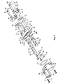
- numeral 1 denotes, as a whole, an embodiment of the connector assembly according to the invention that can be used in electrical systems, for example for powering light sources in shop furniture or fittings, or in commercial refrigerators or in architectural applications, public buildings, schools and hospitals.
- the example illustrated here is of the type with three coupling portions, applicable as a shunt or splitter for carrying currents up to 16 amps and 240 AC volts from an inlet to two outlets.
- the connector assembly 1 comprises a body denoted as a whole by reference numeral 2 and defined by two casing portions 3, 4 made of a plastics material and having frontal juxtaposed flanges 3a, 4a that are connected to one another by screws 5.
- the first casing portion 3 defines a first substantially cylindrical coupling portion 6 (see also Fig. 3 ) for coupling a respective connector (not shown), whereas the second casing portion 4 defines a second and third coupling portion 7, 8 for coupling to respective connectors (not shown).
- the coupling portions 6, 7 are aligned with one another and turned in opposite directions, whereas the coupling portion 8 is arranged parallel to and beside the coupling portion 7.
- the coupling portion 6 is a substantially cylindrical portion with a front face 6a from which three axial cylindrical cavities D extend, distributed circumferentially about the central axis of the cylindrical portion 6.
- the cylindrical cavities D extend over part of the axial extent of the cylindrical portion 6, a cylindrical hole 6c of smaller diameter then extending from the base of each of the cylindrical cavities D as far as the opposite end of the casing element 3.
- the cylindrical portion 6 has two wedge-shaped teeth T formed on the outer surface of the portion 6 in diametrically opposed regions for engagement with corresponding surfaces of the connector (not shown) to be coupled to the portion 6.
- the second and third coupling portions 7, 8 defined by the casing portion 4 each comprise an outer plastics material tubular casing 70, 80 with thin walls that is mounted on a cylindrical base 71 and 81 of the casing portion 4.
- the bases 71, 81 have peripheral portions in relief R that couple to corresponding recessed portions Z of an end edge of the outer casings 70, 80 ( Fig. 3 ) in order to hold the casings 70, 80 on the bases 71, 81.
- Said bases also have, on their outer surface, wedge-shaped teeth T in diametrically opposed regions that cooperate with apertures W in the casings 70, 80 in order to hold the casings 70, 80 on the bases 71, 81.
- the casing portion 4 incorporates three axial tubular elements C distributed so as to be circumferentially equidistant about the geometrical axis of the respective cylindrical base.
- the cavity F in the tubular elements C projects through the respective base 71 or 81 so as to open into a front face 4b of the casing portion 4 (see also Figs. 6 and 7 ).
- seats S are formed in the aforementioned front face 4b as parallel, spaced slots, each of which has a widened end formed by a respective one of the aforementioned cavities F.
- the seats S receive in their interior the bridging elements B made of an electrically conductive metal material, for example a tin-plated copper alloy, in the form of planar laminae having bent ends so as to form resiliently deformable bushings M.
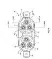
- the metal contacts connected to the coupling portions 6, 7, 8 of the connector assembly according to the invention are formed by two groups of three metal pins R1 and R2 (see Fig. 10 in particular).
- Each of said metal pins is made of an electrically conductive metal material and is produced in one piece by turning.
- Each of the metal pins has an end defining a plug contact P and an opposite end defining a socket contact FE with an end socket defined inside resiliently deformable wings G.
- the metal pins R1 of the first group are longer and more inserted through the entire length of the aligned coupling portions 6, 7 (see Figs. 13 and 14 ) in such a way that the plug ends P form male contacts arranged inside the cylindrical cavities D in the coupling portion 6, whereas the ends FE form female contacts arranged inside the tubular elements C in the coupling portion 7.
- tubular elements C are dimensioned so as to be accommodated inside cavities in a respective coupling connector (not shown), said cavities being completely similar to the cavities D in the coupling portion 6.
- the cavities D are adapted to receive tubular elements of the respective coupling connector, said tubular elements being completely similar to the tubular elements C of the connector assembly shown here.
- the metal pins R2 of the second group are shorter than the metal pins of the first group R1 since use is made of their socket ends FE that are received inside the respective tubular elements C in the coupling portion 8.
- the opposite plug ends P of the pins R2 are instead received in a closed portion 8' of the casing element 3 and are not used as contacts.
- the connector assembly according to the invention has three metal contacts connected to each coupling portion 6, 7, 8 that respectively form the earth contact, the neutral contact, and the phase contact.
- the two metal pins R1 define the neutral and phase contacts
- the metal pin R1 of Fig. 14 defines the earth contact. It can be seen that the pin R1 of Fig. 14 is slightly longer than the pins R1 of Fig. 13 insofar as, when coupling to other connectors, the earth contact has to be coupled before the neutral and phase contacts and, during uncoupling, the earth contact is the last to be disconnected.
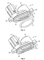
- sealing washers 10 each in the form of a disc with three through-holes are applied over the tubular elements C of the casing portion 4, whereas a ring seal 11 of the O-ring type is placed over the circumferential edge 12 (see Figs. 4 and 5 ) of a front portion in relief 3c of the casing portion 3.
- said front face in relief 3c with the ring seal 11 placed thereon is received, in contact with the front face 4b, inside a peripheral sleeve 12 formed in one piece with the casing 4.
- each of the bridging elements B electrically connects one of the pins R1 of the first group to one of the pins R2 of the second group.
- the planar lamina body of each bridging element B extends substantially in the plane defined by the parallel and spaced axes of the respective pins R1 and R2.
- the circumferential arrangement of the two groups of pins is such that said pins can be connected, in pairs, via the three bridging elements B that are thus arranged in parallel and spaced planes defined by the seats S.
- Each resilient bushing end M of each bridging element B surrounds and clasps a respective pin so said bridging elements B simultaneously serve as electrical connection elements and retaining springs.
- Fig. 15 clearly shows that each of the pins R1, R2 has a set of collars of enlarged diameter R in order to ensure the interference fit of each of the pins R1, R2 inside the respective cavities F (see also Figs. 13 and 14 ).
- Figs. 4 - 11 show the sequence of steps for assembling the connector assembly according to the invention.
- the ring seal 11 is placed round the front portion in relief 3a of the casing portion 3 ( Fig. 5 ).
- the bridging elements B are mounted in the seats S in the front face 4b of the casing portion 4 ( Fig. 6 ).
- the two casing portions 3, 4 thus can be assembled ( Fig. 7 ) and held in position by the screws 5 ( Fig. 8 ).
- the bridging elements B are held in their seats by laminar projections S' (see Figs. 4 and 5 ) that are received inside the seats S in the casing portion 4.
- the two groups of pins R1, R2 are introduced into their respective cavities by being inserted inside the tubular elements C in the coupling portions 7, 8 using the plug ends P as the leading ends.
- the pins are inserted until the socket ends FE contact a stop surface 14 ( Figs. 13 and 14 ) formed inside the internal cavity of the tubular elements C.
- each of the pins R1, R2 is held with an interference fit inside the holes passing through the base portions 71, 81, thanks also to the collars 13.
- each of the resilient bushing ends M of each bridging element B receives its respective pin forming the electrical and mechanical connection, each bridging element B therefore performing both functions.
- the sealing discs 10 can be assembled and the casings 70, 80 can therefore be held on the bases 71, 81 by engagement of the teeth T in the apertures W.
- the resiliently deformable bushings M formed by the ends of the bridging elements B deform so as to surround and accommodate the metal pins, thus giving rise to a normal contact force adapted to ensure mechanical and electrical connection to the pins.
- the purpose of such bridging elements is therefore to distribute the current from an inlet to two outlets and, on the other hand, to integrally incorporate the springs retaining said connection.
Landscapes
- Connector Housings Or Holding Contact Members (AREA)
- Details Of Connecting Devices For Male And Female Coupling (AREA)
- Measurement And Recording Of Electrical Phenomena And Electrical Characteristics Of The Living Body (AREA)
Claims (6)
- Nebenschluss-Steckverbinderbaugruppe für elektrische Anlagen, die einen Korpus (2) umfasst, der wenigstens einen ersten (6), einen zweiten (7) und einen dritten Kupplungsabschnitt (8) zum Kuppeln an jeweilige Steckverbinder einschließt, wobei der erste und der zweite Kupplungsabschnitt (6, 7) miteinander ausgerichtet und in entgegengesetzten Richtungen gedreht sind und der dritte Kupplungsabschnitt (8) parallel zu und neben dem zweiten Kupplungsabschnitt (7) angeordnet ist, wobei jeder der Kupplungsabschnitte (6, 7, 8) mehrere Kontakte (P, FE) hat,
wobei:die Kontakte (P, FE) des ersten und des zweiten Kupplungsabschnitts (6, 7) durch die entgegengesetzten Enden einer ersten Gruppe von Metallstiften mit kreisförmigem Querschnitt (R1), die innerhalb des Korpus (2) der Steckverbinderbaugruppe aufgenommen werden, definiert werden, und die Kontakte (P, FE) des dritten Kupplungsabschnitts (8) durch erste Enden (FE) einer zweiten Gruppe von Metallstiften mit kreisförmigem Querschnitt (R2), die parallel zu und beabstandet von den Stiften der ersten Gruppe (R1) angeordnet sind, definiert werden,jeder Stift der ersten Gruppe (R1) elektrisch mit einem jeweiligen Stift der zweiten Gruppe (R2) verbunden ist, durch ein Metall-Überbrückungselement (B) in der Form eines ebenen Plättchens, das sich im Wesentlichen in der Ebene, welche die Achsen der durch das Überbrückungselement verbundenen Stifte (R1, R2) enthält, erstreckt und integral an jedem Ende einen zurückgebogenen Abschnitt (M) einschließt, der eine elastisch verformbare offene Hülse definiert, die einen jeweiligen Metallstift umschließt und umklammert,dadurch gekennzeichnet, dass die Stifte der ersten Gruppe (R1) und die Stifte der zweiten Gruppe (R2) so angeordnet sind, dass sie in Umgangsrichtung mit gleichem Abstand um eine jeweilige Mittelachse liegen, auf eine solche Weise, dass die Überbrückungselemente (B), die in Paaren die Stifte der zwei Gruppen (R1, R2) verbinden, in unterschiedlichen Ebenen und parallel zueinander liegen. - Steckverbinderbaugruppe nach Anspruch 1, dadurch gekennzeichnet, dass der Korpus (2) einen ersten Gehäuseabschnitt (3) und einen zweiten Gehäuseabschnitt (4), die durch Schrauben (5) und eine zwischen denselben angeordnete Ringdichtung (11) miteinander verbunden sind, hat, wobei der erste Gehäuseabschnitt (3) den ersten Kupplungsabschnitt (6) einschließt und der zweite Gehäuseabschnitt (4) den zweiten und den dritten Kupplungsabschnitt (7, 8) einschließt.
- Steckverbinderbaugruppe nach Anspruch 2, dadurch gekennzeichnet, dass jeder der Metallstifte mit kreisförmigem Querschnitt der ersten und der zweiten Gruppe (R1, R2) integral ein Ende, das als eine Buchse geformt ist (FE), und ein entgegengesetztes Ende, das als ein Stecker geformt ist (P), einschließt und dass jeder der Stifte ebenfalls integral mehrere Manschetten mit vergrößertem Durchmesser (13) zum Einstecken mit einer Presspassung in jeweilige Hohlräume in dem Korpus (2) einschließt.
- Steckverbinderbaugruppe nach Anspruch 3, dadurch gekennzeichnet, dass die Überbrückungselemente (B) in jeweiligen Sitzen (S), die in einer Stirnfläche (4B) des zweiten Gehäuseabschnitts (4) geformt sind, aufgenommen werden, wobei die Sitze (S) in der Form von parallelen, beabstandeten Schlitzen bereitgestellt werden und erweiterte Enden haben, die durch die Hohlräume (F), welche die zuvor erwähnten Metallstifte (R1, R2) aufnehmen, definiert werden und zu der zuvor erwähnten Stirnfläche offen sind, auf eine solche Weise, dass die Metallstifte (R1, R2) in den Korpus (2) der Steckverbinderbaugruppe eingesetzt und in derselben gehalten werden können, sobald zuerst die Überbrückungselemente (B) in ihren Sitzen (S) angeordnet worden sind.
- Steckverbinderbaugruppe nach Anspruch 4, dadurch gekennzeichnet, dass der erste Kupplungsabschnitt (6) ein zylindrischer Korpus ist und eine Stirnfläche (6A) hat, von der aus sich mehrere axiale zylindrische Hohlräume (D) erstrecken, in denen die Steckerenden (P) von jeweiligen Metallstiften (R1) aufgenommen werden.
- Steckverbinderbaugruppe nach Anspruch 4, dadurch gekennzeichnet, dass jeder von dem zweiten und dem dritten Kupplungsabschnitt (7, 8) eine zylindrische Basis (71, 81) umfasst, von der aus sich mehrere axiale röhrenförmige Elemente (C) erstrecken, in denen die Buchsenenden (FE) von jeweiligen Metallstiften (R1, R2) angeordnet sind, wobei jeder von dem zweiten und dem dritten Kupplungsabschnitt (7, 8) ebenfalls ein zylindrisches röhrenförmiges Gehäuse (70, 80), das an die jeweilige Basis (71, 81) gekoppelt ist, einschließt.
Applications Claiming Priority (2)
| Application Number | Priority Date | Filing Date | Title |
|---|---|---|---|
| ITTO2010A000128A IT1398415B1 (it) | 2010-02-22 | 2010-02-22 | Gruppo connettore derivatore per impianti elettrici. |
| PCT/EP2011/052147 WO2011101318A1 (en) | 2010-02-22 | 2011-02-14 | A splitter connector unit for electrical installations |
Publications (2)
| Publication Number | Publication Date |
|---|---|
| EP2539966A1 EP2539966A1 (de) | 2013-01-02 |
| EP2539966B1 true EP2539966B1 (de) | 2015-04-08 |
Family
ID=43027763
Family Applications (1)
| Application Number | Title | Priority Date | Filing Date |
|---|---|---|---|
| EP11703874.5A Active EP2539966B1 (de) | 2010-02-22 | 2011-02-14 | Verteilersteckereinheit für elektrische installationen |
Country Status (7)
| Country | Link |
|---|---|
| US (1) | US8708735B2 (de) |
| EP (1) | EP2539966B1 (de) |
| JP (1) | JP5674214B2 (de) |
| CN (1) | CN102771016B (de) |
| AU (1) | AU2011217375B2 (de) |
| IT (1) | IT1398415B1 (de) |
| WO (1) | WO2011101318A1 (de) |
Cited By (1)
| Publication number | Priority date | Publication date | Assignee | Title |
|---|---|---|---|---|
| DE102018111734B3 (de) | 2018-05-16 | 2019-06-06 | Harting Electric Gmbh & Co. Kg | Hochstromsteckverbinder und Verfahren zu seiner Montage |
Families Citing this family (14)
| Publication number | Priority date | Publication date | Assignee | Title |
|---|---|---|---|---|
| FR2959623B1 (fr) * | 2010-04-30 | 2013-03-15 | Souriau | Dispositif de couplage d'un moteur asynchrone a un cable d'alimentation electrique, moteur asynchrone, et procede de couplage d'un moteur asynchrone a un cable d'alimentation electrique |
| US9124020B2 (en) * | 2011-10-18 | 2015-09-01 | Mitsubishi Electric Corporation | Jumper connector |
| US8608514B2 (en) * | 2012-01-26 | 2013-12-17 | Emerson Electric Co. | Connector block with parallel electrical connection |
| JP5964673B2 (ja) * | 2012-06-28 | 2016-08-03 | タイコエレクトロニクスジャパン合同会社 | 電気コネクタ及びメス型端子 |
| JP5805230B2 (ja) * | 2014-02-04 | 2015-11-04 | タイコエレクトロニクスジャパン合同会社 | 電気コネクタ |
| US9948048B2 (en) | 2015-05-15 | 2018-04-17 | Yazaki North America, Inc. | Splitter terminal and connector |
| FR3062513B1 (fr) * | 2017-01-31 | 2021-04-23 | Renault Sas | Dispositif de connexion electrique avec fonction de consignation integree |
| CN109149194A (zh) * | 2018-10-17 | 2019-01-04 | 上海思方电气技术有限公司 | 一种预埋式固定桥接电连接器 |
| CN111370896B (zh) * | 2018-12-25 | 2024-02-20 | 富士康(昆山)电脑接插件有限公司 | 电连接器及其组合 |
| DE102019111691B4 (de) * | 2019-01-11 | 2020-10-15 | Hanon Systems | Anordnung zum Steckverbinden elektrischer Anschlüsse und Vorrichtung zum Antreiben eines Verdichters mit der Anordnung |
| US11616317B2 (en) * | 2019-01-18 | 2023-03-28 | David Anderson | Angled power pin alignment and crimping fixture |
| USD931230S1 (en) * | 2019-07-31 | 2021-09-21 | Molex, Llc | Connector shroud |
| US12283769B2 (en) * | 2021-09-03 | 2025-04-22 | Alltop Electronics (Suzhou) Ltd. | Electrical connector with high versatility |
| CN115332830B (zh) * | 2022-09-06 | 2025-12-12 | 广东省安富电器有限公司 | 一种分线接头及其制造工艺 |
Family Cites Families (25)
| Publication number | Priority date | Publication date | Assignee | Title |
|---|---|---|---|---|
| CH264105A (fr) * | 1946-02-01 | 1949-09-30 | Nederlanden Staat | Dispositif de connexion électrique. |
| GB853694A (en) * | 1957-08-02 | 1960-11-09 | Belling & Lee Ltd | Improvements in or relating to electrical contact assemblies |
| CH460901A (fr) * | 1967-10-27 | 1968-08-15 | Baillod Frederic | Prise multiple de courant électrique |
| DE2723725C3 (de) * | 1977-05-26 | 1981-06-11 | Abke, Hermann, 4972 Löhne | Elektrische Mehrfachkupplung |
| JPS5575981U (de) * | 1978-11-20 | 1980-05-26 | ||
| JPS6069477U (ja) * | 1983-10-19 | 1985-05-16 | 古河電気工業株式会社 | 電線の分岐接続部 |
| DE8514581U1 (de) * | 1985-05-17 | 1985-10-17 | Konietzny, Bruno, 5920 Bad Berleburg | Mehrfachsteckdose mit eingebautem Netzstecker |
| JPH0141179Y2 (de) * | 1985-12-20 | 1989-12-06 | ||
| US4950171A (en) * | 1989-08-11 | 1990-08-21 | Itt Corporation | Fuel injector connector system |
| US5127382A (en) | 1990-09-17 | 1992-07-07 | Siemens Automotive L.P. | Electrical connector bar for a fuel injector/fuel rail assembly and method of making |
| JPH0469870U (de) * | 1990-10-26 | 1992-06-19 | ||
| JP2549380Y2 (ja) * | 1991-06-25 | 1997-09-30 | ウイトコオブジュピター電通株式会社 | 貫通コンデンサ付コネクタにおけるコネクタピン |
| DE19513880C2 (de) * | 1995-04-18 | 1998-07-09 | Whitaker Corp | Steckverbinder |
| CA2160854A1 (en) | 1995-10-18 | 1997-04-19 | Robert L. Romerein | Top exit coupler |
| JP3049391U (ja) * | 1997-11-19 | 1998-06-09 | 福井鋲螺株式会社 | コネクタ |
| HU223861B1 (hu) * | 1999-06-14 | 2005-02-28 | Antal Natta | Csatlakozó hegesztőpisztoly csatlakoztatásához |
| US6769637B2 (en) * | 2000-12-04 | 2004-08-03 | Autonetworks Technologies, Ltd. | Injector module, injector electric block body, injector main bodies to be used for the same, and ignition coil device module |
| US6669502B1 (en) * | 2002-09-19 | 2003-12-30 | Tyco Electronics Corporation | High-speed axial connector |
| US20040043674A1 (en) * | 2002-08-28 | 2004-03-04 | Dunne Denise E. | DSX jack including contact |
| DE102004018554B4 (de) * | 2004-04-14 | 2018-09-27 | Wago Verwaltungsgesellschaft Mbh | Brücker für elektrische Klemmen |
| JP4898296B2 (ja) * | 2006-05-24 | 2012-03-14 | 三菱電線工業株式会社 | 接続部材 |
| US7641500B2 (en) * | 2007-04-04 | 2010-01-05 | Fci Americas Technology, Inc. | Power cable connector system |
| US7575476B2 (en) * | 2007-08-01 | 2009-08-18 | Tyco Electronics Corporation | Power distribution module and header assembly therefor |
| US7448902B1 (en) * | 2008-04-25 | 2008-11-11 | Tyco Electronics Corporation | Mechanical device showing prior mating |
| JP5176803B2 (ja) * | 2008-09-11 | 2013-04-03 | 住友電装株式会社 | ジョイントコネクタおよびジョイントコネクタ付きワイヤハーネス |
-
2010
- 2010-02-22 IT ITTO2010A000128A patent/IT1398415B1/it active
-
2011
- 2011-02-14 AU AU2011217375A patent/AU2011217375B2/en active Active
- 2011-02-14 JP JP2012553280A patent/JP5674214B2/ja not_active Expired - Fee Related
- 2011-02-14 US US13/580,290 patent/US8708735B2/en active Active
- 2011-02-14 WO PCT/EP2011/052147 patent/WO2011101318A1/en not_active Ceased
- 2011-02-14 CN CN201180010556.3A patent/CN102771016B/zh active Active
- 2011-02-14 EP EP11703874.5A patent/EP2539966B1/de active Active
Cited By (4)
| Publication number | Priority date | Publication date | Assignee | Title |
|---|---|---|---|---|
| DE102018111734B3 (de) | 2018-05-16 | 2019-06-06 | Harting Electric Gmbh & Co. Kg | Hochstromsteckverbinder und Verfahren zu seiner Montage |
| EP3794687A1 (de) * | 2018-05-16 | 2021-03-24 | HARTING Electric GmbH & Co. KG | Hochstromsteckverbinder und verfahren zu seiner montage |
| US11336047B2 (en) | 2018-05-16 | 2022-05-17 | Harting Electric Gmbh & Co. Kg | High-current connector and method for mounting same |
| US11881649B2 (en) | 2018-05-16 | 2024-01-23 | Harting Electric Gmbh & Co. Kg | High-current connector and method for mounting same |
Also Published As
| Publication number | Publication date |
|---|---|
| ITTO20100128A1 (it) | 2011-08-23 |
| CN102771016A (zh) | 2012-11-07 |
| AU2011217375A1 (en) | 2012-10-18 |
| CN102771016B (zh) | 2016-01-20 |
| AU2011217375B2 (en) | 2016-06-09 |
| JP5674214B2 (ja) | 2015-02-25 |
| US8708735B2 (en) | 2014-04-29 |
| IT1398415B1 (it) | 2013-02-22 |
| JP2013520764A (ja) | 2013-06-06 |
| US20120322298A1 (en) | 2012-12-20 |
| EP2539966A1 (de) | 2013-01-02 |
| WO2011101318A1 (en) | 2011-08-25 |
Similar Documents
| Publication | Publication Date | Title |
|---|---|---|
| EP2539966B1 (de) | Verteilersteckereinheit für elektrische installationen | |
| AU2009329951B2 (en) | Electrical connector and method of manufacturing same | |
| US10153595B2 (en) | Plug connector part, shielded plug connector unit and locking sleeve therefor | |
| US7850458B2 (en) | Electrical connector and method of manufacturing same | |
| US8079877B1 (en) | Power adapter connecting in a surface to surface contact | |
| US7967609B2 (en) | System for connecting appliances to wall outlets | |
| WO2006028633A3 (en) | Hermaphroditic socket/adapter | |
| US20130137310A1 (en) | Plug connector for differential data transmission | |
| EP2755283B1 (de) | Benutzerkonfigurierbarer Stecker | |
| EP2479850B1 (de) | Elektrische Hochgeschwindigkeits-Kontaktanordnung | |
| TW201411958A (zh) | 插頭 | |
| CA3112261A1 (en) | Contact assembly for a connector housing, connector housing as well as connector assembly and modular connector set with such a connector housing | |
| AU2020203596A1 (en) | Electrical Socket | |
| EP2951890B1 (de) | Verbinderbaugruppe | |
| US20100120278A1 (en) | Multi-angular power adapter | |
| RU2332762C2 (ru) | Соединительное устройство для контактной группы и рукоятки электрического соединителя | |
| CN208401204U (zh) | 电连接器 | |
| US20090186492A1 (en) | Rotatable electrical plug connector | |
| EP3826117A1 (de) | Austauschkontaktspitze für einen elektrischen kontakt eines steckverbinders | |
| CN219717455U (zh) | 一种多回路电缆中间接头及多回路电缆中间接头装置 | |
| CN216773750U (zh) | 转接头及电器设备 | |
| CN220306617U (zh) | 具有防错功能的电连接器内芯结构及电连接器 | |
| WO2023240312A1 (en) | Electrical power point | |
| WO2024216037A1 (en) | Electrical connector assembly with snap locking features | |
| US9620878B2 (en) | Receptacle assembly of NEMA plugs |
Legal Events
| Date | Code | Title | Description |
|---|---|---|---|
| PUAI | Public reference made under article 153(3) epc to a published international application that has entered the european phase |
Free format text: ORIGINAL CODE: 0009012 |
|
| 17P | Request for examination filed |
Effective date: 20120906 |
|
| AK | Designated contracting states |
Kind code of ref document: A1 Designated state(s): AL AT BE BG CH CY CZ DE DK EE ES FI FR GB GR HR HU IE IS IT LI LT LU LV MC MK MT NL NO PL PT RO RS SE SI SK SM TR |
|
| DAX | Request for extension of the european patent (deleted) | ||
| REG | Reference to a national code |
Ref country code: DE Ref legal event code: R079 Ref document number: 602011015420 Country of ref document: DE Free format text: PREVIOUS MAIN CLASS: H01R0013040000 Ipc: H01R0031020000 |
|
| RIC1 | Information provided on ipc code assigned before grant |
Ipc: H01R 24/38 20110101ALN20140807BHEP Ipc: H01R 13/04 20060101ALI20140807BHEP Ipc: H01R 31/02 20060101AFI20140807BHEP Ipc: H01R 13/41 20060101ALN20140807BHEP Ipc: H01R 13/11 20060101ALI20140807BHEP |
|
| RIC1 | Information provided on ipc code assigned before grant |
Ipc: H01R 13/41 20060101ALN20140808BHEP Ipc: H01R 13/11 20060101ALI20140808BHEP Ipc: H01R 13/04 20060101ALI20140808BHEP Ipc: H01R 31/02 20060101AFI20140808BHEP Ipc: H01R 24/38 20110101ALN20140808BHEP |
|
| GRAP | Despatch of communication of intention to grant a patent |
Free format text: ORIGINAL CODE: EPIDOSNIGR1 |
|
| INTG | Intention to grant announced |
Effective date: 20140922 |
|
| GRAS | Grant fee paid |
Free format text: ORIGINAL CODE: EPIDOSNIGR3 |
|
| GRAA | (expected) grant |
Free format text: ORIGINAL CODE: 0009210 |
|
| AK | Designated contracting states |
Kind code of ref document: B1 Designated state(s): AL AT BE BG CH CY CZ DE DK EE ES FI FR GB GR HR HU IE IS IT LI LT LU LV MC MK MT NL NO PL PT RO RS SE SI SK SM TR |
|
| REG | Reference to a national code |
Ref country code: GB Ref legal event code: FG4D |
|
| REG | Reference to a national code |
Ref country code: CH Ref legal event code: EP |
|
| REG | Reference to a national code |
Ref country code: IE Ref legal event code: FG4D |
|
| REG | Reference to a national code |
Ref country code: AT Ref legal event code: REF Ref document number: 721182 Country of ref document: AT Kind code of ref document: T Effective date: 20150515 |
|
| REG | Reference to a national code |
Ref country code: DE Ref legal event code: R096 Ref document number: 602011015420 Country of ref document: DE Effective date: 20150521 |
|
| REG | Reference to a national code |
Ref country code: NL Ref legal event code: T3 |
|
| REG | Reference to a national code |
Ref country code: AT Ref legal event code: MK05 Ref document number: 721182 Country of ref document: AT Kind code of ref document: T Effective date: 20150408 |
|
| REG | Reference to a national code |
Ref country code: LT Ref legal event code: MG4D |
|
| PG25 | Lapsed in a contracting state [announced via postgrant information from national office to epo] |
Ref country code: NO Free format text: LAPSE BECAUSE OF FAILURE TO SUBMIT A TRANSLATION OF THE DESCRIPTION OR TO PAY THE FEE WITHIN THE PRESCRIBED TIME-LIMIT Effective date: 20150708 Ref country code: PT Free format text: LAPSE BECAUSE OF FAILURE TO SUBMIT A TRANSLATION OF THE DESCRIPTION OR TO PAY THE FEE WITHIN THE PRESCRIBED TIME-LIMIT Effective date: 20150810 Ref country code: ES Free format text: LAPSE BECAUSE OF FAILURE TO SUBMIT A TRANSLATION OF THE DESCRIPTION OR TO PAY THE FEE WITHIN THE PRESCRIBED TIME-LIMIT Effective date: 20150408 Ref country code: LT Free format text: LAPSE BECAUSE OF FAILURE TO SUBMIT A TRANSLATION OF THE DESCRIPTION OR TO PAY THE FEE WITHIN THE PRESCRIBED TIME-LIMIT Effective date: 20150408 Ref country code: FI Free format text: LAPSE BECAUSE OF FAILURE TO SUBMIT A TRANSLATION OF THE DESCRIPTION OR TO PAY THE FEE WITHIN THE PRESCRIBED TIME-LIMIT Effective date: 20150408 Ref country code: HR Free format text: LAPSE BECAUSE OF FAILURE TO SUBMIT A TRANSLATION OF THE DESCRIPTION OR TO PAY THE FEE WITHIN THE PRESCRIBED TIME-LIMIT Effective date: 20150408 |
|
| PG25 | Lapsed in a contracting state [announced via postgrant information from national office to epo] |
Ref country code: LV Free format text: LAPSE BECAUSE OF FAILURE TO SUBMIT A TRANSLATION OF THE DESCRIPTION OR TO PAY THE FEE WITHIN THE PRESCRIBED TIME-LIMIT Effective date: 20150408 Ref country code: IS Free format text: LAPSE BECAUSE OF FAILURE TO SUBMIT A TRANSLATION OF THE DESCRIPTION OR TO PAY THE FEE WITHIN THE PRESCRIBED TIME-LIMIT Effective date: 20150808 Ref country code: GR Free format text: LAPSE BECAUSE OF FAILURE TO SUBMIT A TRANSLATION OF THE DESCRIPTION OR TO PAY THE FEE WITHIN THE PRESCRIBED TIME-LIMIT Effective date: 20150709 Ref country code: AT Free format text: LAPSE BECAUSE OF FAILURE TO SUBMIT A TRANSLATION OF THE DESCRIPTION OR TO PAY THE FEE WITHIN THE PRESCRIBED TIME-LIMIT Effective date: 20150408 Ref country code: RS Free format text: LAPSE BECAUSE OF FAILURE TO SUBMIT A TRANSLATION OF THE DESCRIPTION OR TO PAY THE FEE WITHIN THE PRESCRIBED TIME-LIMIT Effective date: 20150408 |
|
| REG | Reference to a national code |
Ref country code: DE Ref legal event code: R097 Ref document number: 602011015420 Country of ref document: DE |
|
| PG25 | Lapsed in a contracting state [announced via postgrant information from national office to epo] |
Ref country code: DK Free format text: LAPSE BECAUSE OF FAILURE TO SUBMIT A TRANSLATION OF THE DESCRIPTION OR TO PAY THE FEE WITHIN THE PRESCRIBED TIME-LIMIT Effective date: 20150408 Ref country code: EE Free format text: LAPSE BECAUSE OF FAILURE TO SUBMIT A TRANSLATION OF THE DESCRIPTION OR TO PAY THE FEE WITHIN THE PRESCRIBED TIME-LIMIT Effective date: 20150408 |
|
| PLBE | No opposition filed within time limit |
Free format text: ORIGINAL CODE: 0009261 |
|
| STAA | Information on the status of an ep patent application or granted ep patent |
Free format text: STATUS: NO OPPOSITION FILED WITHIN TIME LIMIT |
|
| REG | Reference to a national code |
Ref country code: FR Ref legal event code: PLFP Year of fee payment: 6 |
|
| PG25 | Lapsed in a contracting state [announced via postgrant information from national office to epo] |
Ref country code: SK Free format text: LAPSE BECAUSE OF FAILURE TO SUBMIT A TRANSLATION OF THE DESCRIPTION OR TO PAY THE FEE WITHIN THE PRESCRIBED TIME-LIMIT Effective date: 20150408 Ref country code: RO Free format text: LAPSE BECAUSE OF NON-PAYMENT OF DUE FEES Effective date: 20150408 Ref country code: CZ Free format text: LAPSE BECAUSE OF FAILURE TO SUBMIT A TRANSLATION OF THE DESCRIPTION OR TO PAY THE FEE WITHIN THE PRESCRIBED TIME-LIMIT Effective date: 20150408 Ref country code: PL Free format text: LAPSE BECAUSE OF FAILURE TO SUBMIT A TRANSLATION OF THE DESCRIPTION OR TO PAY THE FEE WITHIN THE PRESCRIBED TIME-LIMIT Effective date: 20150408 |
|
| 26N | No opposition filed |
Effective date: 20160111 |
|
| PG25 | Lapsed in a contracting state [announced via postgrant information from national office to epo] |
Ref country code: IT Free format text: LAPSE BECAUSE OF FAILURE TO SUBMIT A TRANSLATION OF THE DESCRIPTION OR TO PAY THE FEE WITHIN THE PRESCRIBED TIME-LIMIT Effective date: 20150408 |
|
| PG25 | Lapsed in a contracting state [announced via postgrant information from national office to epo] |
Ref country code: SI Free format text: LAPSE BECAUSE OF FAILURE TO SUBMIT A TRANSLATION OF THE DESCRIPTION OR TO PAY THE FEE WITHIN THE PRESCRIBED TIME-LIMIT Effective date: 20150408 Ref country code: BE Free format text: LAPSE BECAUSE OF NON-PAYMENT OF DUE FEES Effective date: 20160229 |
|
| PG25 | Lapsed in a contracting state [announced via postgrant information from national office to epo] |
Ref country code: BE Free format text: LAPSE BECAUSE OF FAILURE TO SUBMIT A TRANSLATION OF THE DESCRIPTION OR TO PAY THE FEE WITHIN THE PRESCRIBED TIME-LIMIT Effective date: 20150408 |
|
| PG25 | Lapsed in a contracting state [announced via postgrant information from national office to epo] |
Ref country code: MC Free format text: LAPSE BECAUSE OF FAILURE TO SUBMIT A TRANSLATION OF THE DESCRIPTION OR TO PAY THE FEE WITHIN THE PRESCRIBED TIME-LIMIT Effective date: 20150408 Ref country code: LU Free format text: LAPSE BECAUSE OF FAILURE TO SUBMIT A TRANSLATION OF THE DESCRIPTION OR TO PAY THE FEE WITHIN THE PRESCRIBED TIME-LIMIT Effective date: 20160214 |
|
| REG | Reference to a national code |
Ref country code: CH Ref legal event code: PL |
|
| PG25 | Lapsed in a contracting state [announced via postgrant information from national office to epo] |
Ref country code: CH Free format text: LAPSE BECAUSE OF NON-PAYMENT OF DUE FEES Effective date: 20160229 Ref country code: LI Free format text: LAPSE BECAUSE OF NON-PAYMENT OF DUE FEES Effective date: 20160229 |
|
| REG | Reference to a national code |
Ref country code: IE Ref legal event code: MM4A |
|
| PG25 | Lapsed in a contracting state [announced via postgrant information from national office to epo] |
Ref country code: IE Free format text: LAPSE BECAUSE OF NON-PAYMENT OF DUE FEES Effective date: 20160214 |
|
| REG | Reference to a national code |
Ref country code: FR Ref legal event code: PLFP Year of fee payment: 7 |
|
| PG25 | Lapsed in a contracting state [announced via postgrant information from national office to epo] |
Ref country code: SE Free format text: LAPSE BECAUSE OF FAILURE TO SUBMIT A TRANSLATION OF THE DESCRIPTION OR TO PAY THE FEE WITHIN THE PRESCRIBED TIME-LIMIT Effective date: 20150408 |
|
| PG25 | Lapsed in a contracting state [announced via postgrant information from national office to epo] |
Ref country code: MT Free format text: LAPSE BECAUSE OF FAILURE TO SUBMIT A TRANSLATION OF THE DESCRIPTION OR TO PAY THE FEE WITHIN THE PRESCRIBED TIME-LIMIT Effective date: 20150408 |
|
| REG | Reference to a national code |
Ref country code: FR Ref legal event code: PLFP Year of fee payment: 8 |
|
| PG25 | Lapsed in a contracting state [announced via postgrant information from national office to epo] |
Ref country code: HU Free format text: LAPSE BECAUSE OF FAILURE TO SUBMIT A TRANSLATION OF THE DESCRIPTION OR TO PAY THE FEE WITHIN THE PRESCRIBED TIME-LIMIT; INVALID AB INITIO Effective date: 20110214 Ref country code: CY Free format text: LAPSE BECAUSE OF FAILURE TO SUBMIT A TRANSLATION OF THE DESCRIPTION OR TO PAY THE FEE WITHIN THE PRESCRIBED TIME-LIMIT Effective date: 20150408 Ref country code: SM Free format text: LAPSE BECAUSE OF FAILURE TO SUBMIT A TRANSLATION OF THE DESCRIPTION OR TO PAY THE FEE WITHIN THE PRESCRIBED TIME-LIMIT Effective date: 20150408 |
|
| PG25 | Lapsed in a contracting state [announced via postgrant information from national office to epo] |
Ref country code: MT Free format text: LAPSE BECAUSE OF FAILURE TO SUBMIT A TRANSLATION OF THE DESCRIPTION OR TO PAY THE FEE WITHIN THE PRESCRIBED TIME-LIMIT Effective date: 20160229 Ref country code: TR Free format text: LAPSE BECAUSE OF FAILURE TO SUBMIT A TRANSLATION OF THE DESCRIPTION OR TO PAY THE FEE WITHIN THE PRESCRIBED TIME-LIMIT Effective date: 20150408 Ref country code: MK Free format text: LAPSE BECAUSE OF FAILURE TO SUBMIT A TRANSLATION OF THE DESCRIPTION OR TO PAY THE FEE WITHIN THE PRESCRIBED TIME-LIMIT Effective date: 20150408 |
|
| PG25 | Lapsed in a contracting state [announced via postgrant information from national office to epo] |
Ref country code: BG Free format text: LAPSE BECAUSE OF FAILURE TO SUBMIT A TRANSLATION OF THE DESCRIPTION OR TO PAY THE FEE WITHIN THE PRESCRIBED TIME-LIMIT Effective date: 20150408 |
|
| PG25 | Lapsed in a contracting state [announced via postgrant information from national office to epo] |
Ref country code: AL Free format text: LAPSE BECAUSE OF FAILURE TO SUBMIT A TRANSLATION OF THE DESCRIPTION OR TO PAY THE FEE WITHIN THE PRESCRIBED TIME-LIMIT Effective date: 20150408 |
|
| PGFP | Annual fee paid to national office [announced via postgrant information from national office to epo] |
Ref country code: NL Payment date: 20200212 Year of fee payment: 10 |
|
| REG | Reference to a national code |
Ref country code: NL Ref legal event code: MM Effective date: 20210301 |
|
| PG25 | Lapsed in a contracting state [announced via postgrant information from national office to epo] |
Ref country code: NL Free format text: LAPSE BECAUSE OF NON-PAYMENT OF DUE FEES Effective date: 20210301 |
|
| PGFP | Annual fee paid to national office [announced via postgrant information from national office to epo] |
Ref country code: FR Payment date: 20231212 Year of fee payment: 14 |
|
| PG25 | Lapsed in a contracting state [announced via postgrant information from national office to epo] |
Ref country code: FR Free format text: LAPSE BECAUSE OF NON-PAYMENT OF DUE FEES Effective date: 20250228 |
|
| PGFP | Annual fee paid to national office [announced via postgrant information from national office to epo] |
Ref country code: GB Payment date: 20260106 Year of fee payment: 16 |
|
| PGFP | Annual fee paid to national office [announced via postgrant information from national office to epo] |
Ref country code: DE Payment date: 20251224 Year of fee payment: 16 |