EP2532050B1 - Bordinterne direktionale flachplattenantenne, fahrzeug mit einer solchen antenne und satellitentelekommunikationssystem mit einem solchen fahrzeug - Google Patents
Bordinterne direktionale flachplattenantenne, fahrzeug mit einer solchen antenne und satellitentelekommunikationssystem mit einem solchen fahrzeug Download PDFInfo
- Publication number
- EP2532050B1 EP2532050B1 EP11700955.5A EP11700955A EP2532050B1 EP 2532050 B1 EP2532050 B1 EP 2532050B1 EP 11700955 A EP11700955 A EP 11700955A EP 2532050 B1 EP2532050 B1 EP 2532050B1
- Authority
- EP
- European Patent Office
- Prior art keywords
- waveguides
- radiating
- antenna
- phase
- antenna according
- Prior art date
- Legal status (The legal status is an assumption and is not a legal conclusion. Google has not performed a legal analysis and makes no representation as to the accuracy of the status listed.)
- Active
Links
Images


Classifications
-
- H—ELECTRICITY
- H01—ELECTRIC ELEMENTS
- H01Q—ANTENNAS, i.e. RADIO AERIALS
- H01Q21/00—Antenna arrays or systems
- H01Q21/24—Combinations of antenna units polarised in different directions for transmitting or receiving circularly and elliptically polarised waves or waves linearly polarised in any direction
-
- H—ELECTRICITY
- H01—ELECTRIC ELEMENTS
- H01Q—ANTENNAS, i.e. RADIO AERIALS
- H01Q21/00—Antenna arrays or systems
- H01Q21/0006—Particular feeding systems
- H01Q21/0037—Particular feeding systems linear waveguide fed arrays
- H01Q21/0043—Slotted waveguides
-
- H—ELECTRICITY
- H01—ELECTRIC ELEMENTS
- H01Q—ANTENNAS, i.e. RADIO AERIALS
- H01Q21/00—Antenna arrays or systems
- H01Q21/0006—Particular feeding systems
- H01Q21/0037—Particular feeding systems linear waveguide fed arrays
- H01Q21/0043—Slotted waveguides
- H01Q21/005—Slotted waveguides arrays
-
- H—ELECTRICITY
- H04—ELECTRIC COMMUNICATION TECHNIQUE
- H04B—TRANSMISSION
- H04B7/00—Radio transmission systems, i.e. using radiation field
- H04B7/14—Relay systems
- H04B7/15—Active relay systems
- H04B7/185—Space-based or airborne stations; Stations for satellite systems
- H04B7/18502—Airborne stations
- H04B7/18506—Communications with or from aircraft, i.e. aeronautical mobile service
- H04B7/18508—Communications with or from aircraft, i.e. aeronautical mobile service with satellite system used as relay, i.e. aeronautical mobile satellite service
Definitions
- the present invention relates to an on-board directive planar antenna, a vehicle comprising such an antenna and a satellite telecommunications system comprising such a vehicle. It applies in particular to the field of satellite telecommunications and more particularly to telecommunications equipment installed on mobile vehicles such as land, sea or aeronautical means of transport to ensure a bi-directional Ka-band connection between a mobile terminal and a earth station via a repeater installed on a satellite. According to a particular embodiment, it also applies to the simultaneous tracking of two separate satellites operating in Ka band and L band respectively.
- Satellite transmissions can be masked by obstacles in the pointing direction of a satellite. Obstacles can be vegetation or infrastructure such as buildings or bridges. It is therefore necessary, to increase the availability of the radio frequency link with a satellite, to have a spatial diversity allowing the tracking of two satellites simultaneously.
- the two satellites having different pointing directions, the simultaneous tracking of two satellites requires a bi-beam antenna with independent pointing, such as an antenna with electronic scanning, or two antennas with mechanical pointing.
- the antenna In the case of an electronic scanning antenna, to cover a territory such as Europe, the antenna must be able to ensure, in transmission and reception, pointing in an angular range between 0 ° and 360 ° in azimuth and between 20 ° and 60 ° on average in elevation.
- each antenna When using a double antenna with mechanical pointing, each antenna generates a beam using an independent mechanical pointing system to point the two satellites simultaneously.
- the pointing of each antenna towards a satellite is carried out by a combination of two mechanical movements.
- a first mechanical movement is obtained by means of a rotating platform arranged in an XY plane and ensuring the orientation of the antenna in azimuth.
- a second movement in elevation is carried out by an annex device, for example a plane mirror, integral with the platform.
- Each antenna conventionally comprises a parabolic reflector and a radiating source illuminating the reflector. To reduce the size of the reflector and reduce the height of the antenna, its periphery is elliptical instead of circular.
- such a simple antenna currently deployed on high-speed trains has a height of the order of 45 cm. Although this height is compatible with current trains, it is too important for future high-speed trains with two bridges for which the height available for the installation of an antenna, between the roof of the train and the overhead lines, is much lower.
- the height of the antenna has an influence on the drag generated by the aircraft as well as on the fuel consumption.
- the current reflector antennas installed on airplanes have a height of the order of 30 cm and cause overconsumption of fuel equivalent to eight additional passengers.
- the antenna is composed of two parallel plates between which circulate longitudinal current components and an array of one dimension of continuous transverse grooves which couple and radiate energy in space.
- the two plates and the network of grooves are mounted on two coplanar plates mechanically rotating independently of one another, the two rotational movements being superimposed and produced in the same plane of the plates.
- the orientation of the lower plate makes it possible to adjust the pointing direction in azimuth
- the orientation of the upper plate makes it possible to obtain a variable inclination of the grooves and thus to modify the pointing direction in elevation of the beam generated by the antenna.
- this antenna initially operating in linear polarization, it is necessary to add an additional orientable polarization grid mounted on the upper face of the antenna to control the plane of polarization of the antenna which increases the complexity of implementation. and the height of the antenna which is then not flat.
- the antenna comprises several alternating planes of substrates and metal planes superimposed one above the other.
- the antenna comprises a first lower metallic plane, then a first substrate plane comprising several sources, the first substrate plane comprising a lateral end forming a parabolic surface on which the waves emitted by the sources are reflected.
- Above the first substrate plane is a second metallic plane having slots for coupling the reflected wave plane, each coupling slot opening out into respective slot waveguides arranged side by side. parallel to each other in the same second substrate plane.
- the guided waves are then emitted in the form of a beam radiated through a plurality of radiating openings formed in a third upper metallic plane.
- This antenna is very elliptical, the dimension of the mirror in its region articulated on the platform being much greater than the dimension of the mirror in its region inclined above the platform, which makes it possible to reduce the height of the antenna to 20 or 30cm, but this height is still too large for an application to means of transport.
- a first object of the invention is to provide a planar on-board directive antenna which does not have the drawbacks of existing antennas and which can be installed on a mobile means of transport.
- the object of the invention is to provide a planar on-board directive antenna, operating in Ka band, very compact in the direction of its height, simple to implement and low cost, capable of remaining pointed. on a continuous satellite whatever the position of the means of transport and allowing control of the plane of polarization without adding an orientable grid.
- a second object of the invention is to produce a very compact on-board hybrid planar antenna operating in Ka band and L band, allowing the simultaneous tracking of two satellites.
- the invention relates to an on-board directive planar antenna as defined in claim 1.
- each rafter forms an angle equal to 90 °.
- the network of guides with radiating slots is mounted on a rotating platform in azimuth.
- the external electronic phase shift circuit comprising a first external phase shifter having an equal phase value at 180 ° intended to supply two waveguides in phase opposition, the other two waveguides being supplied in phase, and a second external phase shifter having a phase value equal to 90 ° intended to establish a phase quadrature between the two waveguides supplied in phase and the two waveguides supplied in phase opposition.
- the planar antenna comprises two networks of waveguides with radiating slits, of identical structure, dedicated respectively to transmission and to reception.
- the planar antenna further comprises a plurality of radiating dipoles in L-band, the radiating dipoles being located on one of the metal plates of the waveguide networks with radiating slots mounted on the rotating platform.
- the invention also relates to a vehicle comprising at least one such flat antenna and a satellite telecommunications system comprising at least one such vehicle.
- the planar antenna partially shown on the Figures 1a and 1b is of tri-plate structure. It comprises a network 5 of radiating slit waveguides comprising an alternating succession of three metal plates M1, M2, M3 respectively lower, intermediate and upper, superposed parallel to one another, and two dielectric substrates Sub1, Sub2 , respectively lower and upper, interposed between two consecutive metal plates.
- the planes of the different layers of the antenna are parallel to an XY plane.
- the height of the antenna is along an axis Z orthogonal to the XY plane.
- the upper dielectric substrate Sub2 supports the waveguides with radiating slits 10, the lower substrate Sub1 supports waveguides 11 intended to supply each waveguide with radiating slits 10 by a microwave signal.
- the network 5 comprises at least four waveguides with radiating slits arranged in the upper substrate and four corresponding feed waveguides arranged in the lower substrate.
- the radiating slit waveguides 10 of the upper substrate and the waveguides 11 of the lower substrate are identical, correspond in pairs and communicate with each other in pairs by means of coupling slots 13 passing through the M2 intermediate metal plate.
- each waveguide 11 of the lower substrate Sub1 comprises two metal walls, lower and upper, respectively formed by the lower metal plates M1 and intermediate M2 and lateral metal walls connecting the two lower metal plates M1 and intermediate M2.
- Each waveguide 11 of the lower substrate Sub1 further comprises a coupling slot 13 passing through the intermediate metal plate M2 and opening into a waveguide 10 of the upper substrate Sub2.
- Each waveguide 10 of the upper substrate Sub2 has two metal walls, lower and upper, respectively formed by the intermediate metal plates M2 and upper M3 and lateral metal walls connecting the two intermediate metal plates M2 and upper M3.
- the waveguides 10, 11 extend along a longitudinal axis parallel to the same direction, which may correspond, for example, to the axis X and have two opposite ends 15, 16 on this axis.
- the waveguides of the upper substrate Sub2 are closed at their two ends 15, 16 by first and second transverse metal walls 17, 18 connecting the three metal plates M1, M2, M3 together while the waveguides of the lower substrate are closed at only one end 16 by the first transverse wall 17, their open end 15 corresponding to a signal input 19.
- Each waveguide 10 of the upper substrate Sub2 further comprises a plurality of radiating slots 20 passing through the upper metal plate M3.
- All the radiating slots 20 arranged in the same waveguide are mutually parallel and oriented in the same direction, for example at 45 ° with respect to the directions X and Y and emit a polarized wave plane parallel to their orientation.
- the radiating slots 20 of two adjacent waveguides 10 are arranged in chevrons, each chevron forming a non-zero angle, for example equal to 90 °.
- all the slits are oriented at 45 ° relative to the X and Y directions but the radiating slits 20 of two adjacent waveguides are arranged in chevrons and form an angle of 90 ° therebetween.
- Each waveguide 11 of the lower substrate Sub1 comprises an internal individual supply circuit 25 capable of receiving an incoming microwave signal 19 applied to its open end, this internal individual supply circuit 25 comprising an internal individual electronic phase shift circuit and amplification comprising an internal phase shifter 21 for controlling the phase of the signal to be transmitted and an internal amplification device 22 of the incoming signal making it possible to control the radiation emitted by the antenna.
- the incoming signal 19 can be emitted for example by an external source 24, for example unique, then divided by a divider 26 connected at the input of each of the waveguides 11 of the lower substrate Sub1.
- the incoming signal 19 in one of the waveguides 11 of the lower substrate Sub1 is transmitted in a corresponding waveguide 10 of the upper substrate Sub2 via the coupling slots 13 in the intermediate metal plate M2 then radiated by the radiating slots 20 A sweep and a deflection of the beam in elevation, in a plane ZX perpendicular to the plane XY of the antenna, is obtained by controlling the law of phase and amplitude applied electronically by the internal internal supply circuits of each guide.
- wave 11 of the lower substrate corresponding to each of the waveguides 10 with radiating slits.
- Each waveguide 11 of the lower substrate Sub1 being supplied individually by an internal circuit 25 and comprising an individual internal electronic phase shift 21 and amplification 22 circuit, the phase control is carried out continuously which makes it possible to continuously control the direction of radiation of the antenna in elevation. Furthermore, the amplification is distributed in each waveguide 11 which allows the use of low power amplifiers and to overcome a complex and bulky external amplification circuit. In addition, no high energy source switching means is required to achieve continuous scanning of the beam.
- the network 5 of radiating slit waveguides further comprises a second external electronic phase shift circuit placed at the input of the network 5, this second phase shift circuit comprising a first external phase shifter 23 having a phase value equal to 180 ° intended to supply the second waveguide with radiating slits in phase opposition with respect to the first waveguide with radiating slits and a second external phase shifter 27 having a phase value equal to 90 ° intended to establish a phase quadrature between the signals feeding the first two waveguides 11 and the signals feeding the third and fourth waveguides 11.
- the first and second waveguides being supplied in opposition to phase, the waves they emit combine vectorially with each other and radiate globally a resultant wave polarized in the X direction, the polarization components in the Y direction canceling each other out.
- the third and fourth waveguides being supplied in phase, the waves which they emit combine vectorially with one another and generally radiate a resultant wave polarized in the direction Y, the components of polarization in the direction X canceling each other out.
- the two resulting waves polarized respectively in the directions X and Y and supplied in phase quadrature then combine with one another in a global wave circularly polarized and emitted by the network of radiating slit waveguides 5.
- the pointing of the beam in azimuth is achieved by rotation of the platform and the pointing of the beam in elevation is given by the phase law applied to the incoming signals 19
- This phase law is obtained by controlling the internal phase shifters 21 and the internal amplifiers 22 integrated in each of the waveguides 11 of the lower substrate Sub1.
- the waveguides 10 with radiating slits operating in a low bandwidth it is possible to split the transmission and reception functions and to use as shown in the figure 2 , a system of planar antennas 6, 8 comprising a first array of slot wave guides dedicated to transmission and a second array of slot wave guides, not shown, dedicated to reception, the two array of slotted waveguides having an identical structure and mounted on the same platform 7 rotating in azimuth.
- the pointing in elevation of each of the transmitting and receiving antennas of the planar antenna system mounted on the rotating platform is achieved by amplification and electronic control of the phases of each of the signals flowing in the slot guides forming the arrays of radiation from the two antennas.
- the height of the antenna without the rotating platform on which it is mounted is a few millimeters.
- the total height of the antenna with the rotating platform 7 is almost equal to the height of the rotating platform, ie of the order of 2 to 3 cm.
- the planar antenna thus produced radiates a circularly polarized wave which meets the height conditions imposed for installation on a means of transport and in particular on a future high-speed train.
- the electronic control of the phases and amplitudes of the signals feeding this antenna comprises a number of active elements, typically less than 50, limited elements.
- the desired coverage area is very large and the aircraft is liable to evolve in areas where the Ka-band satellite is no longer visible but where a Ku-band satellite is accessible.
- Ku-band antennas must operate in linear polarization. Linear polarization is obtained by orienting all the radiating slits of all the waveguides of the upper substrate in the same direction.
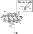
- FIG 4 A very compact on-board hybrid antenna system operating in Ka (and / or Ku) and L-band is shown, allowing the simultaneous tracking of two satellites.
- the L-band antenna is installed on the same rotating platform 7 in azimuth as the Ka and / or Ku antenna.
- the L-band antenna has a plurality of crossed dipoles 40 radiating oriented in two orthogonal directions, each radiating dipole comprising two metal appendages 41, 42 located on one of the upper metal plates M3, intermediate M2 or lower M1 of the antenna operating in Ka band and / or the antenna operating in Ku band.
- These appendages 41, 42 are dimensioned to operate in L-band and therefore do not disturb the Ka or Ku antennas on which they are installed.
- the crossed dipoles are individually controlled in phase by a phase shifter not shown, and radiate according to a phase law which their own while following the azimuth orientation of the platform 7 and imposed by the satellite pointed by the antenna Ka and / or Ku.
- the phase law of the dipoles 41, 42 of the L-band antenna is electronically controlled so as to continuously point a satellite operating in L-band.
- the antenna thus produced is very compact and allows the simultaneous tracking of two satellites operating respectively in Ka-band and L-band or Ku-band and L-band thanks to its operation in Ka-band and Ka-band or in Ka-band, Ku-band and L-band depending on the type of guide networks with radiating slits which are installed on the azimuth platform and the linear and / or circular polarization generated by the phase law combined with the orientation of the radiating slits of these networks.
Claims (9)
- Bidirektionale Bord-Flachantenne, beinhaltend mindestens ein Netzwerk (5) von Hohlwellenleitern mit Strahlschlitzen, dadurch gekennzeichnet, dass:- das Netzwerk (5) von Hohlwellenleitern mit Strahlschlitzen eine abwechselnder Abfolge von drei übereinander liegenden Metallplatten beinhaltet, jeweils einer unteren (M1), einer mittleren (M2) und einer oberen (M3), und von zwei Dielektrikums-Substraten, jeweils einem unteren (Sub1) und einem oberen (Sub2), welche zwischen zwei aufeinanderfolgenden Metallplatten eingelegt sind,- die beiden Substrate, das untere (Sub1) und das obere (Sub2), jeweils mindestens vier benachbarte Hohlwellenleiter (10, 11) beinhalten, wobei die Hohlwellenleiter des unteren Substrates und des oberen Substrates in einer identischen Anzahl vorliegen, und einander paarweise entsprechen und miteinander paarweise in Vermittlung von Kopplungsschlitzen (13) kommunizieren,welche die mittlere Metallplatte (M2) durchqueren,- jeder Hohlwellenleiter (10) des oberen Substrates (Sub2) zudem eine Vielzahl von Strahlschlitzen (20) beinhaltet, welche die obere Metallplatte (M3) durchquert, wobei alle Strahlschlitze (20) eines selben Hohlwellenleiters (10) parallel zueinander und in eine gleiche Richtung ausgerichtet sind, wobei die Strahlschlitze zweier benachbarter Hohlwellenleiter fischgerätmusterartig angeordnet sind,- jeder Hohlwellenleiter (11) des unteren Substrates (Sub1) einen individuellen internen Versorgungsschaltkreis (25) beinhaltet, welcher einen individuellen internen elektronischen Phasenverschiebungs- (21) und Verstärkungsschaltkreis (22) beinhaltet,- die Flacheantenne einen externen elektronischen Phasenverschiebungsschaltkreis beinhaltet, welcher dazu bestimmt ist, eine kreisförmige Polarisation einer durch das Netzwerk von Leitern mit Strahlschlitzen ausgesandten Welle herzustellen.
- Flacheantenne nach Anspruch 1, dadurch gekennzeichnet, dass jedes der Fischgerätsmuster einen Winkel gleich 90° bildet.
- Flachantenne nach einem der Ansprüche 1 oder 2, dadurch gekennzeichnet, dass sie zudem eine im Azimut drehende Plattform (7) beinhaltet und dass das Netzwerk (5) von Leitern mit Strahlschlitzen auf der im Azimut drehenden Plattform (7) montiert ist.
- Flachantenne nach einem der Ansprüche 1 bis 3, dadurch gekennzeichnet, dass der externe elektronische Phasenverschiebungsschaltkreis einen ersten externen Phasenschieber (23) mit einem Phasenwert gleich 180° beinhaltet, welcher dazu bestimmt ist, zwei Hohlwellenleiter (11) gegenphasig zu versorgen, wobei die beiden anderen Hohlwellenleiter (11) gleichphasig versorgt werden, und ein zweiter externer Phasenschieber (27) mit einem Phasenwert gleich 90° dazu bestimmt ist, eine Phasenquadratur zwischen den beiden Hohlwellenleitern (11), welche gleichphasig versorgt werden und den beiden Hohlwellenleitern (11), welche gegenphasig versorgt werden, herzustellen.
- Flachantenne nach Anspruch 4, dadurch gekennzeichnet, dass sie zwei Netzwerke von Hohlwellenleitern mit Strahlschlitzen identischer Struktur beinhaltet, welche jeweils für Sendung und Empfang ausgelegt sind.
- Flachantenne nach Anspruch 5 in Kombination mit Anspruch 3, dadurch gekennzeichnet, dass sie zudem eine Vielzahl von strahlenden Dipolen (41, 42) im Band L beinhaltet, wobei die strahlenden Dipole auf einer der Metallplatten (M1, M2, M3) der Netzwerke von Hohlwellenleitern mit Strahlschlitzen installiert sind, welche an der drehbaren Plattform (7) montiert sind.
- Flachantenne nach Anspruch 5, dadurch gekennzeichnet, dass sie zudem ein Netzwerk von Hohlwellenleitern mit Strahlschlitzen beinhaltet, in welchem alle Strahlschlitze aller Hohlwellenleiter in eine gleiche Richtung ausgerichtet sind.
- Fahrzeug, welches mindestens eine Antenne nach einem der Ansprüche 1 bis 7 beinhaltet.
- Satelliten-Telekommunikationssystem, beinhaltend mindestens ein Fahrzeug nach Anspruch 8.
Applications Claiming Priority (2)
| Application Number | Priority Date | Filing Date | Title |
|---|---|---|---|
| FR1000474A FR2956252B1 (fr) | 2010-02-05 | 2010-02-05 | Antenne plane directive embarquee, vehicule comportant une telle antenne et systeme de telecommunication par satellite comportant un tel vehicule |
| PCT/EP2011/051105 WO2011095425A1 (fr) | 2010-02-05 | 2011-01-27 | Antenne plane directive embarquée, véhicule comportant une telle antenne et système de télécommunication par satellite comportant un tel véhicule |
Publications (2)
| Publication Number | Publication Date |
|---|---|
| EP2532050A1 EP2532050A1 (de) | 2012-12-12 |
| EP2532050B1 true EP2532050B1 (de) | 2020-05-20 |
Family
ID=42647443
Family Applications (1)
| Application Number | Title | Priority Date | Filing Date |
|---|---|---|---|
| EP11700955.5A Active EP2532050B1 (de) | 2010-02-05 | 2011-01-27 | Bordinterne direktionale flachplattenantenne, fahrzeug mit einer solchen antenne und satellitentelekommunikationssystem mit einem solchen fahrzeug |
Country Status (5)
| Country | Link |
|---|---|
| US (1) | US9013359B2 (de) |
| EP (1) | EP2532050B1 (de) |
| JP (1) | JP5786244B2 (de) |
| FR (1) | FR2956252B1 (de) |
| WO (1) | WO2011095425A1 (de) |
Families Citing this family (20)
| Publication number | Priority date | Publication date | Assignee | Title |
|---|---|---|---|---|
| US8669914B2 (en) * | 2011-04-28 | 2014-03-11 | Realtek Semiconductor Corp. | Dual-band antenna and related wireless communication apparatus |
| CN103474780B (zh) * | 2013-09-13 | 2016-03-02 | 电子科技大学 | 基片集成波导腔体缝隙天线 |
| EP3050161B1 (de) * | 2013-09-24 | 2019-08-21 | Duke University | Discrete-dipole-verfahren und -systeme für anwendungen auf komplementären metamaterialien |
| JP5675934B1 (ja) * | 2013-11-06 | 2015-02-25 | 有限会社Nazca | アンテナ装置 |
| US9196940B2 (en) * | 2014-03-07 | 2015-11-24 | Raytheon Company | Waveguide mechanical phase adjuster |
| US9612317B2 (en) * | 2014-08-17 | 2017-04-04 | Google Inc. | Beam forming network for feeding short wall slotted waveguide arrays |
| KR102302466B1 (ko) * | 2014-11-11 | 2021-09-16 | 주식회사 케이엠더블유 | 도파관 슬롯 어레이 안테나 |
| US9851436B2 (en) * | 2015-01-05 | 2017-12-26 | Delphi Technologies, Inc. | Radar antenna assembly with panoramic detection |
| US9620861B1 (en) * | 2015-06-01 | 2017-04-11 | Lockheed Martin Corporation | Configurable joined-chevron fractal pattern antenna, system and method of making same |
| US10033082B1 (en) * | 2015-08-05 | 2018-07-24 | Waymo Llc | PCB integrated waveguide terminations and load |
| CN105024143B (zh) * | 2015-08-06 | 2018-08-28 | 中国电子科技集团公司第三十八研究所 | 一种片式Ka频段宽角扫描卫星通信天线 |
| CN107204518B (zh) * | 2017-04-21 | 2019-04-19 | 西北工业大学 | 一种宽带高效率平板天线 |
| CN109066064B (zh) * | 2018-07-19 | 2020-09-18 | 中国科学院国家空间科学中心 | 一种复合左右手波导缝隙阵单元及天线 |
| CN109004347B (zh) * | 2018-08-07 | 2020-12-11 | 江西师范大学 | 圆极化及双圆极化波导阵列天线及其制作方法 |
| CN111276078A (zh) * | 2020-04-10 | 2020-06-12 | 南京达斯琪数字科技有限公司 | 一种基于双圆极化双向数传模块的旋转显示装置 |
| CN111585028B (zh) * | 2020-05-26 | 2023-09-19 | 华南理工大学 | 一种数字编码全息天线及其调控方法 |
| CN112768882B (zh) * | 2020-12-07 | 2022-07-22 | 重庆邮电大学 | 一种基于双贴片加载的双波束圆极化阵列天线 |
| CN112259962B (zh) * | 2020-12-21 | 2021-03-02 | 东南大学 | 基于双模平行波导的双频段共口径天线阵 |
| CN113451786B (zh) * | 2021-06-25 | 2022-08-16 | 重庆两江卫星移动通信有限公司 | 一种紧凑型馈电网络与圆极化天线阵列的控制方法 |
| CN113571909B (zh) * | 2021-06-30 | 2024-02-09 | 上海中航光电子有限公司 | 天线单元、天线装置以及电子设备 |
Family Cites Families (13)
| Publication number | Priority date | Publication date | Assignee | Title |
|---|---|---|---|---|
| FR2448792A2 (fr) * | 1977-06-24 | 1980-09-05 | Radant Etudes | Antenne hyperfrequence plate, non dispersive a balayage electronique |
| US4691205A (en) * | 1985-06-06 | 1987-09-01 | Rca Corporation | Beam forming network for circularly polarized shaped beam antenna system |
| JPH04358405A (ja) * | 1991-06-05 | 1992-12-11 | Asahi Chem Ind Co Ltd | 導波管スロットアレーアンテナ |
| JPH0563469A (ja) * | 1991-08-29 | 1993-03-12 | Nec Corp | マイクロ波電力増幅器 |
| IL107582A (en) * | 1993-11-12 | 1998-02-08 | Ramot Ramatsity Authority For | Slotted waveguide array antennas |
| JPH11103201A (ja) * | 1997-09-29 | 1999-04-13 | Mitsui Chem Inc | 移相器、移相器アレイおよびフェーズドアレイアンテナ装置 |
| SE514557C2 (sv) * | 1999-07-09 | 2001-03-12 | Ericsson Telefon Ab L M | Anordning för bruk i en gruppantenn för sändning och mottagning på minst en frekvens i minst två polarisationer |
| US6166701A (en) * | 1999-08-05 | 2000-12-26 | Raytheon Company | Dual polarization antenna array with radiating slots and notch dipole elements sharing a common aperture |
| JP2003066134A (ja) * | 2001-08-21 | 2003-03-05 | Furuno Electric Co Ltd | レーダアンテナ |
| US6873301B1 (en) * | 2003-10-07 | 2005-03-29 | Bae Systems Information And Electronic Systems Integration Inc. | Diamond array low-sidelobes flat-plate antenna systems for satellite communication |
| US7202832B2 (en) * | 2004-01-07 | 2007-04-10 | Motia | Vehicle mounted satellite antenna system with ridged waveguide |
| US7379029B2 (en) * | 2005-09-27 | 2008-05-27 | Elta Systems Ltd | Waveguide slot antenna and arrays formed thereof |
| ITRM20080282A1 (it) * | 2008-05-29 | 2009-11-30 | Rf Microtech S R L | Antenna piatta a scansione. |
-
2010
- 2010-02-05 FR FR1000474A patent/FR2956252B1/fr not_active Expired - Fee Related
-
2011
- 2011-01-27 EP EP11700955.5A patent/EP2532050B1/de active Active
- 2011-01-27 WO PCT/EP2011/051105 patent/WO2011095425A1/fr active Application Filing
- 2011-01-27 US US13/577,256 patent/US9013359B2/en not_active Expired - Fee Related
- 2011-01-27 JP JP2012551580A patent/JP5786244B2/ja not_active Expired - Fee Related
Non-Patent Citations (1)
| Title |
|---|
| None * |
Also Published As
| Publication number | Publication date |
|---|---|
| US9013359B2 (en) | 2015-04-21 |
| JP2013519281A (ja) | 2013-05-23 |
| EP2532050A1 (de) | 2012-12-12 |
| US20130057431A1 (en) | 2013-03-07 |
| JP5786244B2 (ja) | 2015-09-30 |
| FR2956252A1 (fr) | 2011-08-12 |
| FR2956252B1 (fr) | 2013-04-26 |
| WO2011095425A1 (fr) | 2011-08-11 |
Similar Documents
| Publication | Publication Date | Title |
|---|---|---|
| EP2532050B1 (de) | Bordinterne direktionale flachplattenantenne, fahrzeug mit einer solchen antenne und satellitentelekommunikationssystem mit einem solchen fahrzeug | |
| EP2532046B1 (de) | Flachplatten-abtastantenne für landfahrzeuganwendung, fahrzeug mit einer solchen antenne und satellitentelekommunikationssystem mit solch einem fahrzeug | |
| EP2415120B1 (de) | Mehrschichtige pillbox-antenne mit parallelen ebenen und entsprechendes antennensystem | |
| EP0600799B1 (de) | Aktive Antenne mit variabler Polarisations-Synthese | |
| EP2654126B1 (de) | Mobile Richtantenne mit Polarisierungsschaltung durch Bewegung der Strahlungspaneele | |
| EP2688142B1 (de) | Mehrfachstrahl-Sende- und Empfangsantenne mit mehreren Quellen pro Strahl, Antennensystem und Satellitentelekommunikationssystem, die eine solche Antenne umfassen | |
| EP1955405B1 (de) | Array-antenne mit irregulärem netz und potentieller kälteredundanz | |
| EP3011639B1 (de) | Speiseanordnung für eine parabolantenne | |
| WO2014040957A1 (fr) | Antenne multibande à inclinaison électrique variable | |
| EP2673842A1 (de) | Wellenleiterantenne mit ringförmigen schlitzen | |
| EP3176875A1 (de) | Aufbau einer aktiven hybriden rekonfigurierbaren strahlbildungsantenne | |
| CA2808511C (fr) | Antenne plane pour terminal fonctionnant en double polarisation circulaire, terminal aeroporte et systeme de telecommunication par satellite comportant au moins une telle antenne | |
| EP0520908B1 (de) | Lineare Gruppenantenne | |
| EP4046241B1 (de) | Grupenantennen | |
| FR2930844A1 (fr) | Antenne rf d'emission et/ou de reception comportant des elements rayonnants excites par couplage electromagnetique sans contact | |
| EP3840115A1 (de) | Kompakte antenne mit resonanzhohlraum | |
| EP3155689B1 (de) | Flachantenne zur satellitenkommunikation | |
| WO2023218008A1 (fr) | Antenne faible profil à balayage electronique bidimensionnel | |
| WO2015189136A1 (fr) | Antenne plate de telecommunication par satellite | |
| WO2021130072A1 (fr) | Antenne parabolique multilobes pour communications par faisceaux hertziens tropospheriques | |
| EP2889955A1 (de) | Kompaktantennenstruktur für Telekommunikationen über Satelliten |
Legal Events
| Date | Code | Title | Description |
|---|---|---|---|
| PUAI | Public reference made under article 153(3) epc to a published international application that has entered the european phase |
Free format text: ORIGINAL CODE: 0009012 |
|
| 17P | Request for examination filed |
Effective date: 20120619 |
|
| AK | Designated contracting states |
Kind code of ref document: A1 Designated state(s): AL AT BE BG CH CY CZ DE DK EE ES FI FR GB GR HR HU IE IS IT LI LT LU LV MC MK MT NL NO PL PT RO RS SE SI SK SM TR |
|
| DAX | Request for extension of the european patent (deleted) | ||
| STAA | Information on the status of an ep patent application or granted ep patent |
Free format text: STATUS: EXAMINATION IS IN PROGRESS |
|
| 17Q | First examination report despatched |
Effective date: 20181219 |
|
| REG | Reference to a national code |
Ref country code: DE Ref legal event code: R079 Ref document number: 602011066922 Country of ref document: DE Free format text: PREVIOUS MAIN CLASS: H01Q0021000000 Ipc: H01Q0021240000 |
|
| RIC1 | Information provided on ipc code assigned before grant |
Ipc: H01Q 21/00 20060101ALI20191018BHEP Ipc: H04B 7/185 20060101ALI20191018BHEP Ipc: H01Q 21/24 20060101AFI20191018BHEP |
|
| GRAP | Despatch of communication of intention to grant a patent |
Free format text: ORIGINAL CODE: EPIDOSNIGR1 |
|
| STAA | Information on the status of an ep patent application or granted ep patent |
Free format text: STATUS: GRANT OF PATENT IS INTENDED |
|
| INTG | Intention to grant announced |
Effective date: 20191209 |
|
| GRAS | Grant fee paid |
Free format text: ORIGINAL CODE: EPIDOSNIGR3 |
|
| GRAA | (expected) grant |
Free format text: ORIGINAL CODE: 0009210 |
|
| STAA | Information on the status of an ep patent application or granted ep patent |
Free format text: STATUS: THE PATENT HAS BEEN GRANTED |
|
| RAP1 | Party data changed (applicant data changed or rights of an application transferred) |
Owner name: THALES |
|
| AK | Designated contracting states |
Kind code of ref document: B1 Designated state(s): AL AT BE BG CH CY CZ DE DK EE ES FI FR GB GR HR HU IE IS IT LI LT LU LV MC MK MT NL NO PL PT RO RS SE SI SK SM TR |
|
| REG | Reference to a national code |
Ref country code: GB Ref legal event code: FG4D Free format text: NOT ENGLISH |
|
| REG | Reference to a national code |
Ref country code: CH Ref legal event code: EP |
|
| REG | Reference to a national code |
Ref country code: DE Ref legal event code: R096 Ref document number: 602011066922 Country of ref document: DE |
|
| REG | Reference to a national code |
Ref country code: AT Ref legal event code: REF Ref document number: 1273230 Country of ref document: AT Kind code of ref document: T Effective date: 20200615 |
|
| REG | Reference to a national code |
Ref country code: LT Ref legal event code: MG4D |
|
| REG | Reference to a national code |
Ref country code: NL Ref legal event code: MP Effective date: 20200520 |
|
| PG25 | Lapsed in a contracting state [announced via postgrant information from national office to epo] |
Ref country code: PT Free format text: LAPSE BECAUSE OF FAILURE TO SUBMIT A TRANSLATION OF THE DESCRIPTION OR TO PAY THE FEE WITHIN THE PRESCRIBED TIME-LIMIT Effective date: 20200921 Ref country code: GR Free format text: LAPSE BECAUSE OF FAILURE TO SUBMIT A TRANSLATION OF THE DESCRIPTION OR TO PAY THE FEE WITHIN THE PRESCRIBED TIME-LIMIT Effective date: 20200821 Ref country code: IS Free format text: LAPSE BECAUSE OF FAILURE TO SUBMIT A TRANSLATION OF THE DESCRIPTION OR TO PAY THE FEE WITHIN THE PRESCRIBED TIME-LIMIT Effective date: 20200920 Ref country code: SE Free format text: LAPSE BECAUSE OF FAILURE TO SUBMIT A TRANSLATION OF THE DESCRIPTION OR TO PAY THE FEE WITHIN THE PRESCRIBED TIME-LIMIT Effective date: 20200520 Ref country code: NO Free format text: LAPSE BECAUSE OF FAILURE TO SUBMIT A TRANSLATION OF THE DESCRIPTION OR TO PAY THE FEE WITHIN THE PRESCRIBED TIME-LIMIT Effective date: 20200820 Ref country code: LT Free format text: LAPSE BECAUSE OF FAILURE TO SUBMIT A TRANSLATION OF THE DESCRIPTION OR TO PAY THE FEE WITHIN THE PRESCRIBED TIME-LIMIT Effective date: 20200520 Ref country code: FI Free format text: LAPSE BECAUSE OF FAILURE TO SUBMIT A TRANSLATION OF THE DESCRIPTION OR TO PAY THE FEE WITHIN THE PRESCRIBED TIME-LIMIT Effective date: 20200520 |
|
| PG25 | Lapsed in a contracting state [announced via postgrant information from national office to epo] |
Ref country code: BG Free format text: LAPSE BECAUSE OF FAILURE TO SUBMIT A TRANSLATION OF THE DESCRIPTION OR TO PAY THE FEE WITHIN THE PRESCRIBED TIME-LIMIT Effective date: 20200820 Ref country code: HR Free format text: LAPSE BECAUSE OF FAILURE TO SUBMIT A TRANSLATION OF THE DESCRIPTION OR TO PAY THE FEE WITHIN THE PRESCRIBED TIME-LIMIT Effective date: 20200520 Ref country code: RS Free format text: LAPSE BECAUSE OF FAILURE TO SUBMIT A TRANSLATION OF THE DESCRIPTION OR TO PAY THE FEE WITHIN THE PRESCRIBED TIME-LIMIT Effective date: 20200520 Ref country code: LV Free format text: LAPSE BECAUSE OF FAILURE TO SUBMIT A TRANSLATION OF THE DESCRIPTION OR TO PAY THE FEE WITHIN THE PRESCRIBED TIME-LIMIT Effective date: 20200520 |
|
| REG | Reference to a national code |
Ref country code: AT Ref legal event code: MK05 Ref document number: 1273230 Country of ref document: AT Kind code of ref document: T Effective date: 20200520 |
|
| PG25 | Lapsed in a contracting state [announced via postgrant information from national office to epo] |
Ref country code: AL Free format text: LAPSE BECAUSE OF FAILURE TO SUBMIT A TRANSLATION OF THE DESCRIPTION OR TO PAY THE FEE WITHIN THE PRESCRIBED TIME-LIMIT Effective date: 20200520 Ref country code: NL Free format text: LAPSE BECAUSE OF FAILURE TO SUBMIT A TRANSLATION OF THE DESCRIPTION OR TO PAY THE FEE WITHIN THE PRESCRIBED TIME-LIMIT Effective date: 20200520 |
|
| PG25 | Lapsed in a contracting state [announced via postgrant information from national office to epo] |
Ref country code: RO Free format text: LAPSE BECAUSE OF FAILURE TO SUBMIT A TRANSLATION OF THE DESCRIPTION OR TO PAY THE FEE WITHIN THE PRESCRIBED TIME-LIMIT Effective date: 20200520 Ref country code: AT Free format text: LAPSE BECAUSE OF FAILURE TO SUBMIT A TRANSLATION OF THE DESCRIPTION OR TO PAY THE FEE WITHIN THE PRESCRIBED TIME-LIMIT Effective date: 20200520 Ref country code: ES Free format text: LAPSE BECAUSE OF FAILURE TO SUBMIT A TRANSLATION OF THE DESCRIPTION OR TO PAY THE FEE WITHIN THE PRESCRIBED TIME-LIMIT Effective date: 20200520 Ref country code: DK Free format text: LAPSE BECAUSE OF FAILURE TO SUBMIT A TRANSLATION OF THE DESCRIPTION OR TO PAY THE FEE WITHIN THE PRESCRIBED TIME-LIMIT Effective date: 20200520 Ref country code: EE Free format text: LAPSE BECAUSE OF FAILURE TO SUBMIT A TRANSLATION OF THE DESCRIPTION OR TO PAY THE FEE WITHIN THE PRESCRIBED TIME-LIMIT Effective date: 20200520 Ref country code: SM Free format text: LAPSE BECAUSE OF FAILURE TO SUBMIT A TRANSLATION OF THE DESCRIPTION OR TO PAY THE FEE WITHIN THE PRESCRIBED TIME-LIMIT Effective date: 20200520 Ref country code: IT Free format text: LAPSE BECAUSE OF FAILURE TO SUBMIT A TRANSLATION OF THE DESCRIPTION OR TO PAY THE FEE WITHIN THE PRESCRIBED TIME-LIMIT Effective date: 20200520 Ref country code: CZ Free format text: LAPSE BECAUSE OF FAILURE TO SUBMIT A TRANSLATION OF THE DESCRIPTION OR TO PAY THE FEE WITHIN THE PRESCRIBED TIME-LIMIT Effective date: 20200520 |
|
| PGFP | Annual fee paid to national office [announced via postgrant information from national office to epo] |
Ref country code: FR Payment date: 20201222 Year of fee payment: 11 |
|
| REG | Reference to a national code |
Ref country code: DE Ref legal event code: R097 Ref document number: 602011066922 Country of ref document: DE |
|
| PG25 | Lapsed in a contracting state [announced via postgrant information from national office to epo] |
Ref country code: SK Free format text: LAPSE BECAUSE OF FAILURE TO SUBMIT A TRANSLATION OF THE DESCRIPTION OR TO PAY THE FEE WITHIN THE PRESCRIBED TIME-LIMIT Effective date: 20200520 Ref country code: PL Free format text: LAPSE BECAUSE OF FAILURE TO SUBMIT A TRANSLATION OF THE DESCRIPTION OR TO PAY THE FEE WITHIN THE PRESCRIBED TIME-LIMIT Effective date: 20200520 |
|
| PLBE | No opposition filed within time limit |
Free format text: ORIGINAL CODE: 0009261 |
|
| STAA | Information on the status of an ep patent application or granted ep patent |
Free format text: STATUS: NO OPPOSITION FILED WITHIN TIME LIMIT |
|
| 26N | No opposition filed |
Effective date: 20210223 |
|
| PG25 | Lapsed in a contracting state [announced via postgrant information from national office to epo] |
Ref country code: SI Free format text: LAPSE BECAUSE OF FAILURE TO SUBMIT A TRANSLATION OF THE DESCRIPTION OR TO PAY THE FEE WITHIN THE PRESCRIBED TIME-LIMIT Effective date: 20200520 |
|
| PGFP | Annual fee paid to national office [announced via postgrant information from national office to epo] |
Ref country code: GB Payment date: 20210120 Year of fee payment: 11 Ref country code: DE Payment date: 20210112 Year of fee payment: 11 |
|
| PG25 | Lapsed in a contracting state [announced via postgrant information from national office to epo] |
Ref country code: MC Free format text: LAPSE BECAUSE OF FAILURE TO SUBMIT A TRANSLATION OF THE DESCRIPTION OR TO PAY THE FEE WITHIN THE PRESCRIBED TIME-LIMIT Effective date: 20200520 |
|
| REG | Reference to a national code |
Ref country code: CH Ref legal event code: PL |
|
| PG25 | Lapsed in a contracting state [announced via postgrant information from national office to epo] |
Ref country code: LU Free format text: LAPSE BECAUSE OF NON-PAYMENT OF DUE FEES Effective date: 20210127 |
|
| REG | Reference to a national code |
Ref country code: BE Ref legal event code: MM Effective date: 20210131 |
|
| PG25 | Lapsed in a contracting state [announced via postgrant information from national office to epo] |
Ref country code: LI Free format text: LAPSE BECAUSE OF NON-PAYMENT OF DUE FEES Effective date: 20210131 Ref country code: CH Free format text: LAPSE BECAUSE OF NON-PAYMENT OF DUE FEES Effective date: 20210131 |
|
| PG25 | Lapsed in a contracting state [announced via postgrant information from national office to epo] |
Ref country code: IE Free format text: LAPSE BECAUSE OF NON-PAYMENT OF DUE FEES Effective date: 20210127 |
|
| PG25 | Lapsed in a contracting state [announced via postgrant information from national office to epo] |
Ref country code: BE Free format text: LAPSE BECAUSE OF NON-PAYMENT OF DUE FEES Effective date: 20210131 |
|
| REG | Reference to a national code |
Ref country code: DE Ref legal event code: R119 Ref document number: 602011066922 Country of ref document: DE |
|
| GBPC | Gb: european patent ceased through non-payment of renewal fee |
Effective date: 20220127 |
|
| PG25 | Lapsed in a contracting state [announced via postgrant information from national office to epo] |
Ref country code: GB Free format text: LAPSE BECAUSE OF NON-PAYMENT OF DUE FEES Effective date: 20220127 Ref country code: DE Free format text: LAPSE BECAUSE OF NON-PAYMENT OF DUE FEES Effective date: 20220802 |
|
| PG25 | Lapsed in a contracting state [announced via postgrant information from national office to epo] |
Ref country code: FR Free format text: LAPSE BECAUSE OF NON-PAYMENT OF DUE FEES Effective date: 20220131 |
|
| PG25 | Lapsed in a contracting state [announced via postgrant information from national office to epo] |
Ref country code: HU Free format text: LAPSE BECAUSE OF FAILURE TO SUBMIT A TRANSLATION OF THE DESCRIPTION OR TO PAY THE FEE WITHIN THE PRESCRIBED TIME-LIMIT; INVALID AB INITIO Effective date: 20110127 Ref country code: CY Free format text: LAPSE BECAUSE OF FAILURE TO SUBMIT A TRANSLATION OF THE DESCRIPTION OR TO PAY THE FEE WITHIN THE PRESCRIBED TIME-LIMIT Effective date: 20200520 |