EP2531756B2 - Pilotmagnetventil - Google Patents
Pilotmagnetventil Download PDFInfo
- Publication number
- EP2531756B2 EP2531756B2 EP11705269.6A EP11705269A EP2531756B2 EP 2531756 B2 EP2531756 B2 EP 2531756B2 EP 11705269 A EP11705269 A EP 11705269A EP 2531756 B2 EP2531756 B2 EP 2531756B2
- Authority
- EP
- European Patent Office
- Prior art keywords
- solenoid valve
- flat
- core
- valve according
- coil
- Prior art date
- Legal status (The legal status is an assumption and is not a legal conclusion. Google has not performed a legal analysis and makes no representation as to the accuracy of the status listed.)
- Active
Links
Images


Classifications
-
- F—MECHANICAL ENGINEERING; LIGHTING; HEATING; WEAPONS; BLASTING
- F16—ENGINEERING ELEMENTS AND UNITS; GENERAL MEASURES FOR PRODUCING AND MAINTAINING EFFECTIVE FUNCTIONING OF MACHINES OR INSTALLATIONS; THERMAL INSULATION IN GENERAL
- F16K—VALVES; TAPS; COCKS; ACTUATING-FLOATS; DEVICES FOR VENTING OR AERATING
- F16K31/00—Actuating devices; Operating means; Releasing devices
- F16K31/02—Actuating devices; Operating means; Releasing devices electric; magnetic
- F16K31/06—Actuating devices; Operating means; Releasing devices electric; magnetic using a magnet, e.g. diaphragm valves, cutting off by means of a liquid
- F16K31/0603—Multiple-way valves
- F16K31/0624—Lift valves
- F16K31/0627—Lift valves with movable valve member positioned between seats
-
- F—MECHANICAL ENGINEERING; LIGHTING; HEATING; WEAPONS; BLASTING
- F16—ENGINEERING ELEMENTS AND UNITS; GENERAL MEASURES FOR PRODUCING AND MAINTAINING EFFECTIVE FUNCTIONING OF MACHINES OR INSTALLATIONS; THERMAL INSULATION IN GENERAL
- F16K—VALVES; TAPS; COCKS; ACTUATING-FLOATS; DEVICES FOR VENTING OR AERATING
- F16K31/00—Actuating devices; Operating means; Releasing devices
- F16K31/02—Actuating devices; Operating means; Releasing devices electric; magnetic
- F16K31/06—Actuating devices; Operating means; Releasing devices electric; magnetic using a magnet, e.g. diaphragm valves, cutting off by means of a liquid
- F16K31/0603—Multiple-way valves
- F16K31/0606—Multiple-way valves fluid passing through the solenoid coil
-
- F—MECHANICAL ENGINEERING; LIGHTING; HEATING; WEAPONS; BLASTING
- F16—ENGINEERING ELEMENTS AND UNITS; GENERAL MEASURES FOR PRODUCING AND MAINTAINING EFFECTIVE FUNCTIONING OF MACHINES OR INSTALLATIONS; THERMAL INSULATION IN GENERAL
- F16K—VALVES; TAPS; COCKS; ACTUATING-FLOATS; DEVICES FOR VENTING OR AERATING
- F16K31/00—Actuating devices; Operating means; Releasing devices
- F16K31/02—Actuating devices; Operating means; Releasing devices electric; magnetic
- F16K31/06—Actuating devices; Operating means; Releasing devices electric; magnetic using a magnet, e.g. diaphragm valves, cutting off by means of a liquid
- F16K31/0644—One-way valve
- F16K31/0651—One-way valve the fluid passing through the solenoid coil
-
- F—MECHANICAL ENGINEERING; LIGHTING; HEATING; WEAPONS; BLASTING
- F16—ENGINEERING ELEMENTS AND UNITS; GENERAL MEASURES FOR PRODUCING AND MAINTAINING EFFECTIVE FUNCTIONING OF MACHINES OR INSTALLATIONS; THERMAL INSULATION IN GENERAL
- F16K—VALVES; TAPS; COCKS; ACTUATING-FLOATS; DEVICES FOR VENTING OR AERATING
- F16K31/00—Actuating devices; Operating means; Releasing devices
- F16K31/02—Actuating devices; Operating means; Releasing devices electric; magnetic
- F16K31/06—Actuating devices; Operating means; Releasing devices electric; magnetic using a magnet, e.g. diaphragm valves, cutting off by means of a liquid
- F16K31/0644—One-way valve
- F16K31/0655—Lift valves
Definitions
- the present invention relates to miniature solenoid valves commonly used in controlling compressed air distribution systems with a slide or flap valve. These miniature solenoid valves act as a multiplier and power controller. Indeed, for a low electrical input power, often less than 1W, the controlled pneumatic output power is greater than 1kW.
- the construction principle of miniature solenoid valves is based on electromagnets whose moving element can have two types of construction.
- the first type of construction is characterized by a cylindrical core, penetrating deep into the central part of a coil belonging to the electromagnet. This construction is commonly called a plunger solenoid valve.
- the second type of construction is characterized by a flat-shaped core, which does not penetrate into the central part of the coil.
- This construction is commonly called a flat moving core solenoid valve.
- a solenoid valve comprising a retaining ring made of magnetic material, inserted into the body of the solenoid valve.
- US 5,374,029 describes a solenoid valve comprising a movable core inside a ring made of magnetic material, used to loop back the magnetic flux.
- a non-magnetic ring is interposed between the coil and this magnetic ring.
- the distance traveled by the flat moving core between its two stable positions is called its stroke.
- the core stroke depends on the dimensions of a large number of parts, but also on the variability of the spring operating points depending on the characteristics of the electromagnet's magnetic forces. This makes it very difficult to produce miniature solenoid valves with a reproducible flow rate value and to guarantee low power consumption.
- the present invention aims, in particular, to propose a miniature solenoid valve with low absorbed power, the moving element of which can be likened to a flat moving core and the stroke and return force of this flat moving core of which can be better controlled, so that the flow rate value is reproducible.
- the solenoid valve comprises all the characteristics of claim 1.
- the flat spring associated with a retaining ring, allows the adjustment of a pre-load force used to seal a supply orifice when the valve is in the rest position, independently of the adjustment of the stroke of the flat movable core.
- the adjustment of the stroke of the flat moving core can be obtained when setting up the subassembly consisting of the coil and the fixed core.
- the feed port and the usage port(s) can be made in the lower part of the body.
- the retaining ring can allow the centering of the fixed core.
- the feed orifice and the use orifice(s) can be made in the bottom, integral with the body.
- the coil body may have several bosses.
- the valve can have a polygonal shape.
- the valve may be cylindrical in shape, with a shoulder in the flat moving core acting as a retainer.
- the valve may have a shoulder.
- a conical spring can be inserted between the shoulder of the valve and the shoulder of the flat moving core.
- a centering washer in association with the flat preload spring, can center and guide the flat moving core, while limiting friction due to the very low thickness of the centering washer.
- This centering washer can be replaced by a second flat spring, of low stiffness, pre-stressed by means of a shoulder in the body allowing the flat mobile core, in association with the flat return spring, to be guided without any friction, neither with the body nor with any other part. internal.
- the flat moving core and the fixed core may have a near-air-gap area with a stepped geometry.
- the outer diameter of the flat movable core can be reduced so as to limit its mass and in that said flat movable core has a bead replacing the guide washer.
- the centering function of the flat mobile core is then obtained, not by a centering washer, but by the bead made directly on the outer diameter of the flat mobile core.
- the external shape of the body section may be truncated on at least two opposite faces, thus forming flats.
- the sealing of the fluid circuit of the solenoid valve with respect to the exterior can be obtained, depending on the construction, by O-rings integrated into the pilot solenoid valve, or by gaskets forming an integral part of the device or apparatus receiving the pilot solenoid valve.
- all the fluid channels connecting the solenoid valve to the external devices are rectilinear and therefore do not present any sudden change in direction of the fluid, hence the absence of additional localized pressure losses, so the air flow is maximum for a low pressure difference.
- the flat moving core used has a particular shape that allows for a force characteristic to be achieved depending on the position adopted, through the influence of the geometric parameters of the air gaps. This shape allows for the magnetic air gap to be reduced without changing the useful stroke and for the attraction characteristic of this flat moving core to be modified.
- the optimization of the resulting dynamic force is also achieved by minimizing the volume, and therefore the mass, of the flat moving core.
- the variability of the operating points of the flat spring is limited by an "in situ" adjustment of the latter, guaranteeing the value of the low absorbed power.
- the miniature solenoid valve according to the invention may also include a one-piece structure of the body connecting the electromagnetic part to the fluidic part, here pneumatic.
- a one-piece structure of the body connecting the electromagnetic part to the fluidic part here pneumatic.
- the flow rate of the feed port is directly controlled by the position of the flat moving core element of the electromagnetic and pneumatic system.
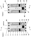
- the magnetic part of the solenoid valve allowing the looping of the magnetic flux generated by the coil 17, is composed of a body 4, a fixed core 3 and a flat mobile core 10 made of ferromagnetic material.
- the flat moving core 10 moves along the main axis of the solenoid valve between the fixed core 3 and the lower part of the body 4.
- the flat moving core 10 which moves along the main axis of the solenoid valve is subjected to an elastic return force due to the flat spring 9. This force, adjustable during assembly, is called pre-load.
- the fluidic part of the solenoid valve is composed of the body 4, the fixed core 3 and the flat movable core 10 comprising a double-sided valve 12.
- the fluidic part of the solenoid valve allows the control of the air flow rates from the supply port 18 to the use port(s) 19 or from the use port(s) 19 to the exhaust port 20.
- An alternative construction consists of controlling the passage of the fluid only between the supply port 18 and use port 19.
- the sealing of the fluid circuit of the solenoid valve is obtained on the one hand by an oblong seal 7 trapped between the coil frame 5 and a retaining ring 8 ensuring internal sealing, and on the other hand by the four O-rings 2, 13, 15 and 26 ensuring external sealing.
- This external sealing function can also be achieved by one or more external gaskets (not shown), forming an integral part of the apparatus or device receiving the pilot solenoid valve, and thereby replacing one or more O-rings 2, 13, 15 and 26.
- the retaining ring 8 is made of non-magnetic material so as not to influence the characteristics of the magnetic field.
- the feed orifice 18 and the use orifice(s) 19 are made in the lower part of the body 4 called the bottom 4D.
- the bottom 4D is integral with the body 4. This makes it possible in particular to limit assembly dispersions and thereby to achieve more precise adjustment of the position of the ring 8 and the travel of the flat movable core 10.
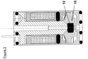
- FIG. 3 illustrates the solenoid valve under tension.
- the core 10 fitted with the valve 12 is then in the high position, and in abutment on the fixed core 3. In this way the exhaust orifice 20 is closed by the action of the valve 12 on the seat 22.
- the coil 17 is composed of a coil frame 5, a winding 6 and two electrical connection pins 1.
- the coil 17, an oblong seal 7 and the fixed core 3 form a coil subassembly 30 whose constitution is more particularly illustrated Figure 5 .
- the coil 17 is slid along the axis of the fixed core 3 until it comes into abutment on it.
- the oblong seal 7 is mounted on the fixed core 3 so as to retain the coil 17 on the fixed core 3.
- connection area of the coil subassembly 30 is more particularly visible Figure 6 .
- the connection pins 1 and their supports 24 provided in the coil frame 5 pass through the fixed core 3 via two through holes 25 provided for this purpose.
- a resin 16 can be injected between the fixed core 3 and the coil frame 5, in order to secure the coil 17 and the fixed core 3. This operation is carried out after insertion of the coil subassembly 30 into the body 4.
- FIG. 7 illustrates an alternative embodiment 10B of the shape of the flat moving core 10.
- the aim here is to achieve a particular magnetic force characteristic between the flat moving core 10B and the end of the fixed core 3B.
- particular geometries are used in the areas close to the motor air gap.
- the magnetic flux is in fact more marked for a conical shape ( Figure 1 ) or stepped ( Figure 7 ), allowing an identical attraction characteristic for reduced electrical energy consumption.
- the efficiency of the electromagnet in the vicinity of the working air gap is higher using one or the other of these two geometries.
- valve 12 illustrated in Figure 8
- This polygonal-shaped valve 12 is inserted into a circular bore in the flat movable core 10.
- This particular polygonal shape, inserted into a circular hole advantageously makes it possible to maintain the valve in its housing, while preventing any deformation of the bearing surfaces on the seats 21, 22 and ensuring the clearance of any burrs relating to the closing of the valve mold.
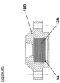
- valve 12B may be cylindrical in shape, with a shoulder 34 in the flat movable core 10D then acting as a retainer. This option is illustrated in Figure 9b .
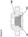
- valve 12C Another geometry of the valve 12C, showing a shoulder 35, can also be produced, so as to obtain greater flexibility of the valve 12C inside the flat movable core 10E, making it possible to promote contact between the flat movable core 10E and the fixed core 3 when the coil 17 is energized. This option is illustrated in Figure 9c .
- the design of the solenoid valve allows the mounting of all the internal components from the rear of the body 4, via an opening 23 particularly suitable for the insertion of the flat movable core 10, the fixed core 3 and the coil 17.
- the design of the solenoid valve also allows the independent adjustment of the stroke and the pre-load. The mounting of the various elements of the solenoid valve is explained below.
- the centering washer 11 and the flat movable core assembly 10, 12 are placed in the lower part of the body 4.
- the flat spring 9 is then inserted and comes into contact with the flat movable core assembly 10, 12.
- the retaining ring 8 is inserted into the body 4 until it makes contact with the flat spring 9.
- the flat spring 9 exerts the preload on the flat movable core assembly 10, 12 and the flat movable core assembly 10, 12 comes into contact with the feed orifice 18.
- the preload force is then checked by a suitable means.
- the retaining ring 8 When the position of the retaining ring 8 is such that the preload force reaches a predefined correct value, the retaining ring 8 is crimped onto the body 4.
- the coil subassembly 30 is then inserted into the body 4 to a position such that the stroke reaches a satisfactory value.
- the value of the stroke is checked by alternating positions between the rest position, coil not powered, and the actuated position, coil powered, so that the stroke is defined with an accuracy of the order of a few tens of micrometers.
- the retaining ring 8 also has the function of centering the lower part of the fixed core 3, relative to the flat mobile core 10, when inserting the coil subassembly 30 into the body 4.
- the body 4 and the coil subassembly 30 are then crimped through the fixed core 3 in the upper part of the solenoid valve.
- the supply orifice 18 is closed by the valve 12, thanks to the preload exerted by the flat spring 9 on the flat movable core 10 making it possible to maintain a force on the seat 21 of the supply orifice 18, necessary to ensure the isolation of the latter from the other orifices 19 and 20.
- the use orifice(s) 19 and the exhaust orifice 20 are then connected, via one or more connecting orifice(s) 14 of the flat movable core 10. Note that the flat spring 9 as well as the centering washer 11 are sufficiently perforated so as not to disturb the passage of the fluid.
- the flat moving core 10 In the actuated position, with the coil powered, the flat moving core 10 is magnetically attracted by the fixed core 3 until contact between these two parts, called bonding.
- the exhaust orifice 20 is then closed by the valve 12.
- the pressure exerted on the latter by the compressed air coming from the supply orifice 18 makes it possible to maintain a force on the seat 22 of the exhaust orifice 20, necessary to ensure the isolation of the latter from the other orifices 18 and 19.
- the supply orifice 18 and the use orifice(s) 19 are then connected.
- FIGS 11 to 14 illustrate examples of the embodiment of body 4, the lateral faces of which can be truncated on two opposite faces ( Figures 13 and 14 ) or on four sides ( Figures 11 and 12 ). The side faces then become flats.
- the localized reduction in the thickness of the body 4 thus caused allows the optimization of the crimping operations of the coil subassembly 30 and the body 4 as well as the holding ring 8 with this same body 4, while maintaining a necessary and sufficient section of magnetic material in the thick zones in order to ensure the circulation of the magnetic flux without saturation.
- These embodiments also make it possible to limit the lateral size of the product in at least one direction.
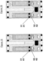
- FIGS. 15 and 16 illustrate alternative embodiments relating to the use of the oblong-shaped seal 7, ensuring the internal sealing of the product.
- This oblong seal 7 is then replaced by two O-rings 31 and 32, the respective housings 41 and 42 of which are made either in the coil frame 5 ( Figure 15 ), or in the retaining ring 8 ( Figure 16 ).
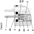
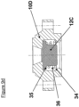
- FIG. 17 illustrates an alternative embodiment 4C of the body 4 and 10C of the flat movable core 10.
- the outer diameter of the flat movable core 10C is reduced, in order to further limit the impact of the mass of this flat movable core 10C on the performance of the product.
- the guide washer 11 is then removed and the guiding function of the flat movable core 10C is then replaced by a bead 28, produced on the flat movable core 10C.
- This bead 28 is sized so as to limit as much as possible the friction between the flat movable core 10C and the body 4C.
- the connecting orifice(s) 14, 19 are produced in the body 4C.
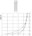
- FIG. 18 illustrates the influence of the air gap geometry on the attraction curve of the flat moving core.
- the attraction force is represented on the ordinate while the air gap is indicated on the abscissa.
- Three geometries are considered: a flat moving core with a flat air gap, a flat moving core with a conical air gap, and a flat moving core with a stepped air gap.
Landscapes
- Engineering & Computer Science (AREA)
- General Engineering & Computer Science (AREA)
- Mechanical Engineering (AREA)
- Magnetically Actuated Valves (AREA)
Claims (14)
- Magnetventil mit einem Elektromagneten (17, 4, 3, 10), der aus einem beweglichen flachen Kern (10), einem feststehenden Kern (3) und einer Spule (17) besteht, umfassend einen Körper (4), der ebenfalls zum Elektromagneten gehört und eine auf der Rückseite des Körpers (4) und entgegengesetzt zum Eingangsanschluss (18) gelegene Öffnung (23) umfasst, die zum Einsetzen des beweglichen flachen Kerns (10), des festen Kerns (3) und der Spule (17) geeignet ist,
wobei das Magnetventil auch einen Haltering (8), der aus einem nicht magnetischen Material ausgeführt ist, und eine Flachfeder (9) umfasst, dadurch gekennzeichnet, dass der Körper (4) fest mit dem Haltering (8) verbunden ist, wobei der Haltering (8) auf den Körper (4) aufgepresst ist, und dass die Flachfeder (9) zwischen dem Haltering (8) und dem beweglichen flachen Kern (10) zusammengedrückt ist. - Magnetventil nach Anspruch 1, dadurch gekennzeichnet, dass die Flachfeder (9), die dem Haltering (8) zugeordnet ist, das Einstellen einer Vorspannkraft ermöglicht, die dazu dient, einen Eingangsanschluss (18) abzudichten, wenn das Ventil in der Ruhestellung ist, und dies unabhängig von der Einstellung des Weges des beweglichen flachen Kerns (10).
- Magnetventil nach Anspruch 1 oder 2, dadurch gekennzeichnet, dass das Einstellen des Weges des beweglichen flachen Kerns (10) beim Einsetzen der Spule (17) und des feststehenden Kerns (3) erhalten wird.
- Magnetventil nach einem der vorhergehenden Ansprüche, dadurch gekennzeichnet, dass der Haltering (8) das Zentrieren des feststehenden Kerns (3) ermöglicht.
- Magnetventil nach einem der vorhergehenden Ansprüche, dadurch gekennzeichnet, dass der Eingangsanschluss (18) und der oder die Arbeitsanschlüsse (19) in dem fest mit dem Körper (4) verbundenen Boden (4D) ausgeführt sind.
- Magnetventil nach einem der vorhergehenden Ansprüche, dadurch gekennzeichnet, dass das Gehäuse (5) der Spule (17) mehrere Erhebungen (33) aufweist.
- Magnetventil nach einem der vorhergehenden Ansprüche, dadurch gekennzeichnet, dass der Dichtkörper (12) des Magnetventils eine polygonale Form aufweist.
- Magnetventil nach einem der vorhergehenden Ansprüche, dadurch gekennzeichnet, dass der Dichtkörper (12B) des Magnetventils zylindrisch ist, wobei eine Schulter (34) im beweglichen flachen Kern (10D) als Rückhaltung fungiert.
- Magnetventil nach einem der vorhergehenden Ansprüche, dadurch gekennzeichnet, dass der Dichtkörper (12C) des Magnetventils eine Schulter (35) aufweist.
- Magnetventil nach den Ansprüchen 8 und 9, dadurch gekennzeichnet, dass eine Kegelfeder (36) zwischen der Schulter (35) des Dichtkörpers (12C) und der Schulter (34) des beweglichen flachen Kerns (10D) eingesetzt ist.
- Magnetventil nach einem der vorhergehenden Ansprüche, dadurch gekennzeichnet, dass der bewegliche flache Kern (10) und der feststehende Kern (3) in der Nähe des Spaltes einen gestuften Bereich umfassen.
- Magnetventil nach einem der vorhergehenden Ansprüche, dadurch gekennzeichnet, dass der Außendurchmesser des beweglichen flachen Kerns (10) reduziert ist, so dass seine Masse begrenzt ist, und dass der bewegliche flache Kern (10) über einen Wulst (28) als Ersatz für eine Führungsscheibe (11) des Magnetventils verfügt.
- Magnetventil nach einem der vorhergehenden Ansprüche, dadurch gekennzeichnet, dass die äußere Form des Querschnitts des Körpers (4) auf mindestens zwei entgegengesetzten Seiten abgeschnitten ist, so dass Abflachungen gebildet werden.
- Magnetventil nach einem der vorhergehenden Ansprüche, dadurch gekennzeichnet, dass alle Medienkanäle (18), (19), (20), die das Magnetventil mit externen Vorrichtungen verbinden, geradlinig sind.
Applications Claiming Priority (2)
| Application Number | Priority Date | Filing Date | Title |
|---|---|---|---|
| FR1000398A FR2955908B1 (fr) | 2010-02-02 | 2010-02-02 | Electrovanne pilote |
| PCT/IB2011/050415 WO2011095928A1 (fr) | 2010-02-02 | 2011-01-31 | Electrovanne pilote |
Publications (3)
| Publication Number | Publication Date |
|---|---|
| EP2531756A1 EP2531756A1 (de) | 2012-12-12 |
| EP2531756B1 EP2531756B1 (de) | 2019-08-14 |
| EP2531756B2 true EP2531756B2 (de) | 2025-04-23 |
Family
ID=42989282
Family Applications (1)
| Application Number | Title | Priority Date | Filing Date |
|---|---|---|---|
| EP11705269.6A Active EP2531756B2 (de) | 2010-02-02 | 2011-01-31 | Pilotmagnetventil |
Country Status (7)
| Country | Link |
|---|---|
| US (1) | US9273791B2 (de) |
| EP (1) | EP2531756B2 (de) |
| JP (1) | JP5979790B2 (de) |
| CN (1) | CN102869910B (de) |
| ES (1) | ES2751152T5 (de) |
| FR (1) | FR2955908B1 (de) |
| WO (1) | WO2011095928A1 (de) |
Families Citing this family (33)
| Publication number | Priority date | Publication date | Assignee | Title |
|---|---|---|---|---|
| DE102011077069A1 (de) * | 2011-06-07 | 2012-12-13 | Robert Bosch Gmbh | Elektromagnetisch betätigbares Ventil |
| US8839815B2 (en) | 2011-12-15 | 2014-09-23 | Honeywell International Inc. | Gas valve with electronic cycle counter |
| US9995486B2 (en) | 2011-12-15 | 2018-06-12 | Honeywell International Inc. | Gas valve with high/low gas pressure detection |
| US8899264B2 (en) | 2011-12-15 | 2014-12-02 | Honeywell International Inc. | Gas valve with electronic proof of closure system |
| US9851103B2 (en) | 2011-12-15 | 2017-12-26 | Honeywell International Inc. | Gas valve with overpressure diagnostics |
| US9835265B2 (en) | 2011-12-15 | 2017-12-05 | Honeywell International Inc. | Valve with actuator diagnostics |
| US9074770B2 (en) | 2011-12-15 | 2015-07-07 | Honeywell International Inc. | Gas valve with electronic valve proving system |
| US8947242B2 (en) | 2011-12-15 | 2015-02-03 | Honeywell International Inc. | Gas valve with valve leakage test |
| US9557059B2 (en) | 2011-12-15 | 2017-01-31 | Honeywell International Inc | Gas valve with communication link |
| US9846440B2 (en) | 2011-12-15 | 2017-12-19 | Honeywell International Inc. | Valve controller configured to estimate fuel comsumption |
| US8905063B2 (en) | 2011-12-15 | 2014-12-09 | Honeywell International Inc. | Gas valve with fuel rate monitor |
| FR2993035B1 (fr) | 2012-07-05 | 2015-02-20 | Asco Joucomatic Sa | Electrovanne du type a noyau plat et ressort plat. |
| US9234661B2 (en) | 2012-09-15 | 2016-01-12 | Honeywell International Inc. | Burner control system |
| US10422531B2 (en) | 2012-09-15 | 2019-09-24 | Honeywell International Inc. | System and approach for controlling a combustion chamber |
| EP2868970B1 (de) | 2013-10-29 | 2020-04-22 | Honeywell Technologies Sarl | Regelungsvorrichtung |
| US10024439B2 (en) | 2013-12-16 | 2018-07-17 | Honeywell International Inc. | Valve over-travel mechanism |
| JP2015138937A (ja) * | 2014-01-24 | 2015-07-30 | 新電元メカトロニクス株式会社 | ソレノイド |
| CN104089072A (zh) * | 2014-06-17 | 2014-10-08 | 贵州新安航空机械有限责任公司 | 一种增强电磁力的电磁阀铁芯结构 |
| JP6200869B2 (ja) * | 2014-08-20 | 2017-09-20 | 株式会社コガネイ | 電磁弁 |
| US9841122B2 (en) | 2014-09-09 | 2017-12-12 | Honeywell International Inc. | Gas valve with electronic valve proving system |
| US9645584B2 (en) | 2014-09-17 | 2017-05-09 | Honeywell International Inc. | Gas valve with electronic health monitoring |
| US10503181B2 (en) | 2016-01-13 | 2019-12-10 | Honeywell International Inc. | Pressure regulator |
| US10564062B2 (en) | 2016-10-19 | 2020-02-18 | Honeywell International Inc. | Human-machine interface for gas valve |
| US20180157279A1 (en) * | 2016-12-02 | 2018-06-07 | RAM Manufacturing Company, Inc. | Electronic Fluid Metering Valve |
| US10578220B2 (en) | 2017-02-27 | 2020-03-03 | Bimba Manufacturing Company | Proportionally controlled pinch valves, systems and methods |
| US10422438B2 (en) * | 2017-04-19 | 2019-09-24 | Fisher Controls International Llc | Electro-pneumatic converters and related methods |
| US11073281B2 (en) | 2017-12-29 | 2021-07-27 | Honeywell International Inc. | Closed-loop programming and control of a combustion appliance |
| US10697815B2 (en) | 2018-06-09 | 2020-06-30 | Honeywell International Inc. | System and methods for mitigating condensation in a sensor module |
| AT16929U1 (de) * | 2019-05-28 | 2020-12-15 | Zieger Dipl Ing Andreas | Kombinationsventil |
| DE102020005978B4 (de) | 2020-09-30 | 2022-09-29 | Staiger Lebensräume Gmbh & Co. Kg | Ventil |
| KR102854827B1 (ko) * | 2020-11-10 | 2025-09-04 | 현대자동차주식회사 | 솔레노이드 밸브 |
| DE102021212172A1 (de) | 2021-10-28 | 2023-05-04 | Robert Bosch Gesellschaft mit beschränkter Haftung | Magnetventil |
| CN118361576A (zh) * | 2024-04-29 | 2024-07-19 | 采埃孚商用车系统(青岛)有限公司 | 电磁阀及其装配方法 |
Family Cites Families (34)
| Publication number | Priority date | Publication date | Assignee | Title |
|---|---|---|---|---|
| US3508568A (en) * | 1967-11-29 | 1970-04-28 | Marotta Valve Corp | Pressure responsive valves |
| US3921670A (en) * | 1974-07-01 | 1975-11-25 | Clippard Instr Lab Inc | Magnetically operated valve with spider armature |
| JPS5312251B2 (de) * | 1974-12-17 | 1978-04-27 | ||
| US4196751A (en) * | 1976-01-15 | 1980-04-08 | Johnson Controls, Inc. | Electric to fluid signal valve unit |
| US4210890A (en) * | 1978-09-27 | 1980-07-01 | Warner Electric Brake & Clutch Company | Field assembly for an electromagnet |
| JPS58214084A (ja) * | 1982-06-08 | 1983-12-13 | Nippon Denso Co Ltd | 電磁弁 |
| JPH0272880U (de) * | 1988-11-21 | 1990-06-04 | ||
| JP3063983B2 (ja) * | 1989-05-22 | 2000-07-12 | 株式会社エステック | 流量制御弁 |
| JPH039180A (ja) * | 1989-06-02 | 1991-01-17 | Mitsubishi Electric Corp | 弁装置 |
| JPH0536175U (ja) * | 1990-12-17 | 1993-05-18 | 株式会社コガネイ | 電磁弁 |
| FR2685429B1 (fr) | 1991-12-23 | 1995-02-10 | Eaton Sa Monaco | Electrovanne a noyau mobile plat. |
| US5306076A (en) * | 1992-05-20 | 1994-04-26 | G. W. Lisk Company, Inc. | Proportional control valve with pressure compensation |
| US5374029A (en) * | 1992-06-26 | 1994-12-20 | Wright Components, Inc. | Solenoid flow control valve and frictionless plunger assembly |
| JP3810488B2 (ja) * | 1996-08-13 | 2006-08-16 | 株式会社ニッキ | 燃料噴射弁 |
| JPH10318413A (ja) | 1997-05-14 | 1998-12-04 | Citizen Electron Co Ltd | 流量コントロール弁 |
| EP1008790B1 (de) | 1997-08-25 | 2006-07-05 | Mitsubishi Denki Kabushiki Kaisha | Arbeitszyklus-magnetventil |
| JP4077915B2 (ja) * | 1997-12-12 | 2008-04-23 | 株式会社不二工機 | 電磁弁及び該電磁弁を備えた多段式流量制御弁 |
| DE19820341C2 (de) * | 1998-05-07 | 2000-04-06 | Daimler Chrysler Ag | Betätigungsvorrichtung für eine Hochdruck-Einspritzdüse für flüssige Einspritzmedien |
| DE19827069B4 (de) | 1998-06-18 | 2008-09-18 | Steuerungstechnik Staiger Gmbh & Co. Produktions-Vertriebs-Kg | Ventil |
| DE19827874B4 (de) | 1998-06-23 | 2006-12-07 | Steuerungstechnik Staiger Gmbh & Co. Produktions-Vertriebs-Kg | Ventil |
| US6220569B1 (en) * | 2000-01-07 | 2001-04-24 | Clippard Instrument Laboratory, Inc. | Electrically controlled proportional valve |
| ATE287057T1 (de) | 2000-12-19 | 2005-01-15 | Fluid Automation Syst | Elektromagnetventil |
| ATE335152T1 (de) | 2002-03-28 | 2006-08-15 | Fluid Automation Syst | Elektromagnetisches ventil |
| DE20205488U1 (de) * | 2002-04-10 | 2003-08-28 | Steuerungstechnik Staiger GmbH & Co. Produktions-Vertriebs-KG, 74391 Erligheim | Ventil |
| DE10215592C1 (de) | 2002-04-10 | 2003-05-15 | Staiger Steuerungstech | Ventil |
| DE50310748D1 (de) | 2003-11-29 | 2008-12-18 | Asco Joucomatic Gmbh | Elektromagnetisches Ventil |
| JP4296081B2 (ja) * | 2003-12-09 | 2009-07-15 | シーケーディ株式会社 | 電磁弁 |
| JP4686340B2 (ja) * | 2005-11-15 | 2011-05-25 | シーケーディ株式会社 | プロセスガス制御弁の付着物除去方法及びプロセスガス制御弁の制御装置 |
| EP2064472B1 (de) | 2006-09-07 | 2016-08-31 | Fluid Automation Systems S.A. | Bistabiles ventil |
| DE102007059054A1 (de) * | 2007-12-06 | 2009-06-10 | Eks Elektromagnetik Gmbh | Elektromagnetische Stellvorrichtung |
| DE102008017764B4 (de) | 2008-04-08 | 2014-10-30 | Staiger Gmbh & Co. Kg | Ventil |
| DE202008017153U1 (de) | 2008-08-12 | 2009-04-02 | Staiger Gmbh & Co. Kg | Ventil |
| CN201344272Y (zh) * | 2009-03-15 | 2009-11-11 | 蒋可贞 | 活塞式先导电磁阀 |
| US8128060B2 (en) * | 2009-03-25 | 2012-03-06 | Valve Tech, Inc. | Non-sliding solenoid valve |
-
2010
- 2010-02-02 FR FR1000398A patent/FR2955908B1/fr active Active
-
2011
- 2011-01-31 JP JP2012551716A patent/JP5979790B2/ja active Active
- 2011-01-31 WO PCT/IB2011/050415 patent/WO2011095928A1/fr not_active Ceased
- 2011-01-31 CN CN201180008277.3A patent/CN102869910B/zh active Active
- 2011-01-31 EP EP11705269.6A patent/EP2531756B2/de active Active
- 2011-01-31 US US13/576,238 patent/US9273791B2/en active Active
- 2011-01-31 ES ES11705269T patent/ES2751152T5/es active Active
Also Published As
| Publication number | Publication date |
|---|---|
| ES2751152T3 (es) | 2020-03-30 |
| EP2531756B1 (de) | 2019-08-14 |
| WO2011095928A1 (fr) | 2011-08-11 |
| CN102869910A (zh) | 2013-01-09 |
| CN102869910B (zh) | 2014-09-24 |
| FR2955908A1 (fr) | 2011-08-05 |
| JP5979790B2 (ja) | 2016-08-31 |
| FR2955908B1 (fr) | 2012-05-04 |
| JP2013519051A (ja) | 2013-05-23 |
| US20120298896A1 (en) | 2012-11-29 |
| ES2751152T5 (en) | 2025-09-01 |
| US9273791B2 (en) | 2016-03-01 |
| EP2531756A1 (de) | 2012-12-12 |
Similar Documents
| Publication | Publication Date | Title |
|---|---|---|
| EP2531756B2 (de) | Pilotmagnetventil | |
| EP3524866B1 (de) | Flüssigkeitsventil | |
| EP2333298B1 (de) | Elektromagnetisches Steuerventil eines Injektors oder zur Druckregulierung eines Hochdruckkraftstoffakkumulators | |
| FR2935771A1 (fr) | Dispositif de commande de l'alimentation d'un systeme avec un fluide | |
| FR2872242A1 (fr) | Electrovanne comportant un induit dont la face frontale n'est pas lisse | |
| FR2589975A1 (fr) | Valve de commande | |
| FR2956715A1 (fr) | Soupape electromagnetique pour commander un fluide | |
| FR2962779A1 (fr) | Electrovanne equipee d'un ressort forme | |
| WO2011048470A1 (en) | Fluid-biased hydraulic control valve with armature piston | |
| FR2689599A1 (fr) | Distributeur à commande électromagnétique, à trois voies et trois positions. | |
| FR2998025A1 (fr) | Vanne | |
| EP3209877B1 (de) | Kraftstoffeinspritzer | |
| FR2956716A1 (fr) | Soupape electromagnetique pour commander un fluide | |
| FR2889621A1 (fr) | Actionneur electromagnetique comportant un tube magnetique et destine a actionner une vanne hydraulique ou pneumatique | |
| EP1815174B1 (de) | Ein mittel zum druckausgleich auf beiden seiten des ventils umfassendes ventilsystem | |
| EP3098403B1 (de) | Vorrichtung zur steuerung der zufuhr einer unter druck stehenden flüssigkeit | |
| FR3029591B1 (fr) | Soupape electromagnetique de regulation et/ou de limitation de pression | |
| EP0006770B1 (de) | Elektromagnetisches Ventil, insbesondere für einen Vergaser | |
| US20140231681A1 (en) | Electromagnetically-actuated piloted valve | |
| FR3007802B1 (fr) | Soupape de commande de systeme d'injection a rampe commune | |
| FR2977293A1 (fr) | Electrovanne | |
| EP3507482A1 (de) | Spulenanordnung | |
| EP2640959A1 (de) | Druckregler und kraftstoffversorgungsvorrichtung mit einem derartigen regler | |
| FR2565660A1 (fr) | Ensemble de soupape anticavitation | |
| FR2967809A1 (fr) | Installation d'actionnement electromagnetique comportant un boitier, un induit mobile et une bobine |
Legal Events
| Date | Code | Title | Description |
|---|---|---|---|
| PUAI | Public reference made under article 153(3) epc to a published international application that has entered the european phase |
Free format text: ORIGINAL CODE: 0009012 |
|
| 17P | Request for examination filed |
Effective date: 20120731 |
|
| AK | Designated contracting states |
Kind code of ref document: A1 Designated state(s): AL AT BE BG CH CY CZ DE DK EE ES FI FR GB GR HR HU IE IS IT LI LT LU LV MC MK MT NL NO PL PT RO RS SE SI SK SM TR |
|
| DAX | Request for extension of the european patent (deleted) | ||
| 17Q | First examination report despatched |
Effective date: 20140408 |
|
| RAP1 | Party data changed (applicant data changed or rights of an application transferred) |
Owner name: ASCO SAS |
|
| GRAP | Despatch of communication of intention to grant a patent |
Free format text: ORIGINAL CODE: EPIDOSNIGR1 |
|
| STAA | Information on the status of an ep patent application or granted ep patent |
Free format text: STATUS: GRANT OF PATENT IS INTENDED |
|
| INTG | Intention to grant announced |
Effective date: 20190121 |
|
| GRAJ | Information related to disapproval of communication of intention to grant by the applicant or resumption of examination proceedings by the epo deleted |
Free format text: ORIGINAL CODE: EPIDOSDIGR1 |
|
| STAA | Information on the status of an ep patent application or granted ep patent |
Free format text: STATUS: EXAMINATION IS IN PROGRESS |
|
| GRAP | Despatch of communication of intention to grant a patent |
Free format text: ORIGINAL CODE: EPIDOSNIGR1 |
|
| STAA | Information on the status of an ep patent application or granted ep patent |
Free format text: STATUS: GRANT OF PATENT IS INTENDED |
|
| INTC | Intention to grant announced (deleted) | ||
| INTG | Intention to grant announced |
Effective date: 20190411 |
|
| GRAS | Grant fee paid |
Free format text: ORIGINAL CODE: EPIDOSNIGR3 |
|
| GRAA | (expected) grant |
Free format text: ORIGINAL CODE: 0009210 |
|
| STAA | Information on the status of an ep patent application or granted ep patent |
Free format text: STATUS: THE PATENT HAS BEEN GRANTED |
|
| AK | Designated contracting states |
Kind code of ref document: B1 Designated state(s): AL AT BE BG CH CY CZ DE DK EE ES FI FR GB GR HR HU IE IS IT LI LT LU LV MC MK MT NL NO PL PT RO RS SE SI SK SM TR |
|
| REG | Reference to a national code |
Ref country code: GB Ref legal event code: FG4D Free format text: NOT ENGLISH |
|
| REG | Reference to a national code |
Ref country code: CH Ref legal event code: EP Ref country code: AT Ref legal event code: REF Ref document number: 1167430 Country of ref document: AT Kind code of ref document: T Effective date: 20190815 |
|
| REG | Reference to a national code |
Ref country code: IE Ref legal event code: FG4D Free format text: LANGUAGE OF EP DOCUMENT: FRENCH |
|
| REG | Reference to a national code |
Ref country code: DE Ref legal event code: R096 Ref document number: 602011061238 Country of ref document: DE |
|
| REG | Reference to a national code |
Ref country code: NL Ref legal event code: MP Effective date: 20190814 |
|
| REG | Reference to a national code |
Ref country code: LT Ref legal event code: MG4D |
|
| PG25 | Lapsed in a contracting state [announced via postgrant information from national office to epo] |
Ref country code: NL Free format text: LAPSE BECAUSE OF FAILURE TO SUBMIT A TRANSLATION OF THE DESCRIPTION OR TO PAY THE FEE WITHIN THE PRESCRIBED TIME-LIMIT Effective date: 20190814 Ref country code: LT Free format text: LAPSE BECAUSE OF FAILURE TO SUBMIT A TRANSLATION OF THE DESCRIPTION OR TO PAY THE FEE WITHIN THE PRESCRIBED TIME-LIMIT Effective date: 20190814 Ref country code: FI Free format text: LAPSE BECAUSE OF FAILURE TO SUBMIT A TRANSLATION OF THE DESCRIPTION OR TO PAY THE FEE WITHIN THE PRESCRIBED TIME-LIMIT Effective date: 20190814 Ref country code: SE Free format text: LAPSE BECAUSE OF FAILURE TO SUBMIT A TRANSLATION OF THE DESCRIPTION OR TO PAY THE FEE WITHIN THE PRESCRIBED TIME-LIMIT Effective date: 20190814 Ref country code: PT Free format text: LAPSE BECAUSE OF FAILURE TO SUBMIT A TRANSLATION OF THE DESCRIPTION OR TO PAY THE FEE WITHIN THE PRESCRIBED TIME-LIMIT Effective date: 20191216 Ref country code: HR Free format text: LAPSE BECAUSE OF FAILURE TO SUBMIT A TRANSLATION OF THE DESCRIPTION OR TO PAY THE FEE WITHIN THE PRESCRIBED TIME-LIMIT Effective date: 20190814 Ref country code: BG Free format text: LAPSE BECAUSE OF FAILURE TO SUBMIT A TRANSLATION OF THE DESCRIPTION OR TO PAY THE FEE WITHIN THE PRESCRIBED TIME-LIMIT Effective date: 20191114 Ref country code: NO Free format text: LAPSE BECAUSE OF FAILURE TO SUBMIT A TRANSLATION OF THE DESCRIPTION OR TO PAY THE FEE WITHIN THE PRESCRIBED TIME-LIMIT Effective date: 20191114 |
|
| REG | Reference to a national code |
Ref country code: AT Ref legal event code: MK05 Ref document number: 1167430 Country of ref document: AT Kind code of ref document: T Effective date: 20190814 |
|
| PG25 | Lapsed in a contracting state [announced via postgrant information from national office to epo] |
Ref country code: IS Free format text: LAPSE BECAUSE OF FAILURE TO SUBMIT A TRANSLATION OF THE DESCRIPTION OR TO PAY THE FEE WITHIN THE PRESCRIBED TIME-LIMIT Effective date: 20191214 Ref country code: LV Free format text: LAPSE BECAUSE OF FAILURE TO SUBMIT A TRANSLATION OF THE DESCRIPTION OR TO PAY THE FEE WITHIN THE PRESCRIBED TIME-LIMIT Effective date: 20190814 Ref country code: AL Free format text: LAPSE BECAUSE OF FAILURE TO SUBMIT A TRANSLATION OF THE DESCRIPTION OR TO PAY THE FEE WITHIN THE PRESCRIBED TIME-LIMIT Effective date: 20190814 Ref country code: GR Free format text: LAPSE BECAUSE OF FAILURE TO SUBMIT A TRANSLATION OF THE DESCRIPTION OR TO PAY THE FEE WITHIN THE PRESCRIBED TIME-LIMIT Effective date: 20191115 Ref country code: RS Free format text: LAPSE BECAUSE OF FAILURE TO SUBMIT A TRANSLATION OF THE DESCRIPTION OR TO PAY THE FEE WITHIN THE PRESCRIBED TIME-LIMIT Effective date: 20190814 |
|
| REG | Reference to a national code |
Ref country code: ES Ref legal event code: FG2A Ref document number: 2751152 Country of ref document: ES Kind code of ref document: T3 Effective date: 20200330 |
|
| PG25 | Lapsed in a contracting state [announced via postgrant information from national office to epo] |
Ref country code: TR Free format text: LAPSE BECAUSE OF FAILURE TO SUBMIT A TRANSLATION OF THE DESCRIPTION OR TO PAY THE FEE WITHIN THE PRESCRIBED TIME-LIMIT Effective date: 20190814 |
|
| PG25 | Lapsed in a contracting state [announced via postgrant information from national office to epo] |
Ref country code: DK Free format text: LAPSE BECAUSE OF FAILURE TO SUBMIT A TRANSLATION OF THE DESCRIPTION OR TO PAY THE FEE WITHIN THE PRESCRIBED TIME-LIMIT Effective date: 20190814 Ref country code: AT Free format text: LAPSE BECAUSE OF FAILURE TO SUBMIT A TRANSLATION OF THE DESCRIPTION OR TO PAY THE FEE WITHIN THE PRESCRIBED TIME-LIMIT Effective date: 20190814 Ref country code: EE Free format text: LAPSE BECAUSE OF FAILURE TO SUBMIT A TRANSLATION OF THE DESCRIPTION OR TO PAY THE FEE WITHIN THE PRESCRIBED TIME-LIMIT Effective date: 20190814 Ref country code: PL Free format text: LAPSE BECAUSE OF FAILURE TO SUBMIT A TRANSLATION OF THE DESCRIPTION OR TO PAY THE FEE WITHIN THE PRESCRIBED TIME-LIMIT Effective date: 20190814 Ref country code: RO Free format text: LAPSE BECAUSE OF FAILURE TO SUBMIT A TRANSLATION OF THE DESCRIPTION OR TO PAY THE FEE WITHIN THE PRESCRIBED TIME-LIMIT Effective date: 20190814 |
|
| REG | Reference to a national code |
Ref country code: DE Ref legal event code: R026 Ref document number: 602011061238 Country of ref document: DE |
|
| PLBI | Opposition filed |
Free format text: ORIGINAL CODE: 0009260 |
|
| PG25 | Lapsed in a contracting state [announced via postgrant information from national office to epo] |
Ref country code: SM Free format text: LAPSE BECAUSE OF FAILURE TO SUBMIT A TRANSLATION OF THE DESCRIPTION OR TO PAY THE FEE WITHIN THE PRESCRIBED TIME-LIMIT Effective date: 20190814 Ref country code: SK Free format text: LAPSE BECAUSE OF FAILURE TO SUBMIT A TRANSLATION OF THE DESCRIPTION OR TO PAY THE FEE WITHIN THE PRESCRIBED TIME-LIMIT Effective date: 20190814 Ref country code: IS Free format text: LAPSE BECAUSE OF FAILURE TO SUBMIT A TRANSLATION OF THE DESCRIPTION OR TO PAY THE FEE WITHIN THE PRESCRIBED TIME-LIMIT Effective date: 20200224 Ref country code: CZ Free format text: LAPSE BECAUSE OF FAILURE TO SUBMIT A TRANSLATION OF THE DESCRIPTION OR TO PAY THE FEE WITHIN THE PRESCRIBED TIME-LIMIT Effective date: 20190814 |
|
| PLAX | Notice of opposition and request to file observation + time limit sent |
Free format text: ORIGINAL CODE: EPIDOSNOBS2 |
|
| 26 | Opposition filed |
Opponent name: STAIGER GMBH & CO. KG Effective date: 20200513 |
|
| PG2D | Information on lapse in contracting state deleted |
Ref country code: IS |
|
| PG25 | Lapsed in a contracting state [announced via postgrant information from national office to epo] |
Ref country code: SI Free format text: LAPSE BECAUSE OF FAILURE TO SUBMIT A TRANSLATION OF THE DESCRIPTION OR TO PAY THE FEE WITHIN THE PRESCRIBED TIME-LIMIT Effective date: 20190814 Ref country code: MC Free format text: LAPSE BECAUSE OF FAILURE TO SUBMIT A TRANSLATION OF THE DESCRIPTION OR TO PAY THE FEE WITHIN THE PRESCRIBED TIME-LIMIT Effective date: 20190814 |
|
| REG | Reference to a national code |
Ref country code: CH Ref legal event code: PL |
|
| GBPC | Gb: european patent ceased through non-payment of renewal fee |
Effective date: 20200131 |
|
| REG | Reference to a national code |
Ref country code: BE Ref legal event code: MM Effective date: 20200131 |
|
| PG25 | Lapsed in a contracting state [announced via postgrant information from national office to epo] |
Ref country code: LU Free format text: LAPSE BECAUSE OF NON-PAYMENT OF DUE FEES Effective date: 20200131 Ref country code: GB Free format text: LAPSE BECAUSE OF NON-PAYMENT OF DUE FEES Effective date: 20200131 |
|
| PLBB | Reply of patent proprietor to notice(s) of opposition received |
Free format text: ORIGINAL CODE: EPIDOSNOBS3 |
|
| PG25 | Lapsed in a contracting state [announced via postgrant information from national office to epo] |
Ref country code: BE Free format text: LAPSE BECAUSE OF NON-PAYMENT OF DUE FEES Effective date: 20200131 Ref country code: LI Free format text: LAPSE BECAUSE OF NON-PAYMENT OF DUE FEES Effective date: 20200131 Ref country code: CH Free format text: LAPSE BECAUSE OF NON-PAYMENT OF DUE FEES Effective date: 20200131 |
|
| PG25 | Lapsed in a contracting state [announced via postgrant information from national office to epo] |
Ref country code: IE Free format text: LAPSE BECAUSE OF NON-PAYMENT OF DUE FEES Effective date: 20200131 |
|
| PLCK | Communication despatched that opposition was rejected |
Free format text: ORIGINAL CODE: EPIDOSNREJ1 |
|
| APBM | Appeal reference recorded |
Free format text: ORIGINAL CODE: EPIDOSNREFNO |
|
| APBP | Date of receipt of notice of appeal recorded |
Free format text: ORIGINAL CODE: EPIDOSNNOA2O |
|
| APAH | Appeal reference modified |
Free format text: ORIGINAL CODE: EPIDOSCREFNO |
|
| PG25 | Lapsed in a contracting state [announced via postgrant information from national office to epo] |
Ref country code: MT Free format text: LAPSE BECAUSE OF FAILURE TO SUBMIT A TRANSLATION OF THE DESCRIPTION OR TO PAY THE FEE WITHIN THE PRESCRIBED TIME-LIMIT Effective date: 20190814 Ref country code: CY Free format text: LAPSE BECAUSE OF FAILURE TO SUBMIT A TRANSLATION OF THE DESCRIPTION OR TO PAY THE FEE WITHIN THE PRESCRIBED TIME-LIMIT Effective date: 20190814 |
|
| PG25 | Lapsed in a contracting state [announced via postgrant information from national office to epo] |
Ref country code: MK Free format text: LAPSE BECAUSE OF FAILURE TO SUBMIT A TRANSLATION OF THE DESCRIPTION OR TO PAY THE FEE WITHIN THE PRESCRIBED TIME-LIMIT Effective date: 20190814 |
|
| APBQ | Date of receipt of statement of grounds of appeal recorded |
Free format text: ORIGINAL CODE: EPIDOSNNOA3O |
|
| APBU | Appeal procedure closed |
Free format text: ORIGINAL CODE: EPIDOSNNOA9O |
|
| P01 | Opt-out of the competence of the unified patent court (upc) registered |
Effective date: 20240503 |
|
| PUAH | Patent maintained in amended form |
Free format text: ORIGINAL CODE: 0009272 |
|
| STAA | Information on the status of an ep patent application or granted ep patent |
Free format text: STATUS: PATENT MAINTAINED AS AMENDED |
|
| PGFP | Annual fee paid to national office [announced via postgrant information from national office to epo] |
Ref country code: DE Payment date: 20241218 Year of fee payment: 15 |
|
| PGFP | Annual fee paid to national office [announced via postgrant information from national office to epo] |
Ref country code: ES Payment date: 20250203 Year of fee payment: 15 |
|
| 27A | Patent maintained in amended form |
Effective date: 20250423 |
|
| AK | Designated contracting states |
Kind code of ref document: B2 Designated state(s): AL AT BE BG CH CY CZ DE DK EE ES FI FR GB GR HR HU IE IS IT LI LT LU LV MC MK MT NL NO PL PT RO RS SE SI SK SM TR |
|
| REG | Reference to a national code |
Ref country code: DE Ref legal event code: R102 Ref document number: 602011061238 Country of ref document: DE |
|
| PGFP | Annual fee paid to national office [announced via postgrant information from national office to epo] |
Ref country code: IT Payment date: 20250107 Year of fee payment: 15 |
|
| REG | Reference to a national code |
Ref country code: ES Ref legal event code: DC2A Ref document number: 2751152 Country of ref document: ES Kind code of ref document: T5 Effective date: 20250901 |
|
| PGFP | Annual fee paid to national office [announced via postgrant information from national office to epo] |
Ref country code: FR Payment date: 20251217 Year of fee payment: 16 |