EP2530263A1 - Système de commande active du bruit pour systèmes d'échappement et procédé de commande associé - Google Patents
Système de commande active du bruit pour systèmes d'échappement et procédé de commande associé Download PDFInfo
- Publication number
- EP2530263A1 EP2530263A1 EP12170274A EP12170274A EP2530263A1 EP 2530263 A1 EP2530263 A1 EP 2530263A1 EP 12170274 A EP12170274 A EP 12170274A EP 12170274 A EP12170274 A EP 12170274A EP 2530263 A1 EP2530263 A1 EP 2530263A1
- Authority
- EP
- European Patent Office
- Prior art keywords
- sound
- control
- exhaust system
- exhaust
- combustion engine
- Prior art date
- Legal status (The legal status is an assumption and is not a legal conclusion. Google has not performed a legal analysis and makes no representation as to the accuracy of the status listed.)
- Granted
Links
Images


Classifications
-
- F—MECHANICAL ENGINEERING; LIGHTING; HEATING; WEAPONS; BLASTING
- F01—MACHINES OR ENGINES IN GENERAL; ENGINE PLANTS IN GENERAL; STEAM ENGINES
- F01N—GAS-FLOW SILENCERS OR EXHAUST APPARATUS FOR MACHINES OR ENGINES IN GENERAL; GAS-FLOW SILENCERS OR EXHAUST APPARATUS FOR INTERNAL COMBUSTION ENGINES
- F01N1/00—Silencing apparatus characterised by method of silencing
- F01N1/06—Silencing apparatus characterised by method of silencing by using interference effect
- F01N1/065—Silencing apparatus characterised by method of silencing by using interference effect by using an active noise source, e.g. speakers
-
- F—MECHANICAL ENGINEERING; LIGHTING; HEATING; WEAPONS; BLASTING
- F16—ENGINEERING ELEMENTS AND UNITS; GENERAL MEASURES FOR PRODUCING AND MAINTAINING EFFECTIVE FUNCTIONING OF MACHINES OR INSTALLATIONS; THERMAL INSULATION IN GENERAL
- F16L—PIPES; JOINTS OR FITTINGS FOR PIPES; SUPPORTS FOR PIPES, CABLES OR PROTECTIVE TUBING; MEANS FOR THERMAL INSULATION IN GENERAL
- F16L55/00—Devices or appurtenances for use in, or in connection with, pipes or pipe systems
- F16L55/02—Energy absorbers; Noise absorbers
- F16L55/033—Noise absorbers
- F16L55/0333—Noise absorbers by means of an active system
-
- G—PHYSICS
- G10—MUSICAL INSTRUMENTS; ACOUSTICS
- G10K—SOUND-PRODUCING DEVICES; METHODS OR DEVICES FOR PROTECTING AGAINST, OR FOR DAMPING, NOISE OR OTHER ACOUSTIC WAVES IN GENERAL; ACOUSTICS NOT OTHERWISE PROVIDED FOR
- G10K11/00—Methods or devices for transmitting, conducting or directing sound in general; Methods or devices for protecting against, or for damping, noise or other acoustic waves in general
- G10K11/16—Methods or devices for protecting against, or for damping, noise or other acoustic waves in general
- G10K11/175—Methods or devices for protecting against, or for damping, noise or other acoustic waves in general using interference effects; Masking sound
- G10K11/178—Methods or devices for protecting against, or for damping, noise or other acoustic waves in general using interference effects; Masking sound by electro-acoustically regenerating the original acoustic waves in anti-phase
- G10K11/1781—Methods or devices for protecting against, or for damping, noise or other acoustic waves in general using interference effects; Masking sound by electro-acoustically regenerating the original acoustic waves in anti-phase characterised by the analysis of input or output signals, e.g. frequency range, modes, transfer functions
- G10K11/17821—Methods or devices for protecting against, or for damping, noise or other acoustic waves in general using interference effects; Masking sound by electro-acoustically regenerating the original acoustic waves in anti-phase characterised by the analysis of input or output signals, e.g. frequency range, modes, transfer functions characterised by the analysis of the input signals only
-
- G—PHYSICS
- G10—MUSICAL INSTRUMENTS; ACOUSTICS
- G10K—SOUND-PRODUCING DEVICES; METHODS OR DEVICES FOR PROTECTING AGAINST, OR FOR DAMPING, NOISE OR OTHER ACOUSTIC WAVES IN GENERAL; ACOUSTICS NOT OTHERWISE PROVIDED FOR
- G10K11/00—Methods or devices for transmitting, conducting or directing sound in general; Methods or devices for protecting against, or for damping, noise or other acoustic waves in general
- G10K11/16—Methods or devices for protecting against, or for damping, noise or other acoustic waves in general
- G10K11/175—Methods or devices for protecting against, or for damping, noise or other acoustic waves in general using interference effects; Masking sound
- G10K11/178—Methods or devices for protecting against, or for damping, noise or other acoustic waves in general using interference effects; Masking sound by electro-acoustically regenerating the original acoustic waves in anti-phase
- G10K11/1787—General system configurations
- G10K11/17879—General system configurations using both a reference signal and an error signal
- G10K11/17883—General system configurations using both a reference signal and an error signal the reference signal being derived from a machine operating condition, e.g. engine RPM or vehicle speed
-
- F—MECHANICAL ENGINEERING; LIGHTING; HEATING; WEAPONS; BLASTING
- F01—MACHINES OR ENGINES IN GENERAL; ENGINE PLANTS IN GENERAL; STEAM ENGINES
- F01N—GAS-FLOW SILENCERS OR EXHAUST APPARATUS FOR MACHINES OR ENGINES IN GENERAL; GAS-FLOW SILENCERS OR EXHAUST APPARATUS FOR INTERNAL COMBUSTION ENGINES
- F01N2390/00—Arrangements for controlling or regulating exhaust apparatus
-
- G—PHYSICS
- G10—MUSICAL INSTRUMENTS; ACOUSTICS
- G10K—SOUND-PRODUCING DEVICES; METHODS OR DEVICES FOR PROTECTING AGAINST, OR FOR DAMPING, NOISE OR OTHER ACOUSTIC WAVES IN GENERAL; ACOUSTICS NOT OTHERWISE PROVIDED FOR
- G10K2210/00—Details of active noise control [ANC] covered by G10K11/178 but not provided for in any of its subgroups
- G10K2210/10—Applications
- G10K2210/128—Vehicles
- G10K2210/1282—Automobiles
- G10K2210/12822—Exhaust pipes or mufflers
-
- G—PHYSICS
- G10—MUSICAL INSTRUMENTS; ACOUSTICS
- G10K—SOUND-PRODUCING DEVICES; METHODS OR DEVICES FOR PROTECTING AGAINST, OR FOR DAMPING, NOISE OR OTHER ACOUSTIC WAVES IN GENERAL; ACOUSTICS NOT OTHERWISE PROVIDED FOR
- G10K2210/00—Details of active noise control [ANC] covered by G10K11/178 but not provided for in any of its subgroups
- G10K2210/30—Means
- G10K2210/301—Computational
- G10K2210/3033—Information contained in memory, e.g. stored signals or transfer functions
Definitions
- the invention relates to an active noise control system for exhaust systems and a method for controlling the same.
- the present invention relates to at least one of an active cancellation and reduction and alteration of sound-waves in exhaust systems of combustion engine driven vehicles.
- noises are generated because of the working cycles (in particular sucking-in and compressing a fuel-air mixture, ignition/expansion and exhausting the combusted fuel-air mixture) taking place in succession.
- These noises on the one hand pass through the combustion engine as solid-borne sound and are radiated off the outside of the combustion engine as airborne sound.
- the noises pass through an exhaust system of the combustion engine as airborne sound together with the combusted fuel-air mixture.
- the noises passing through the combustion engine as solid-borne sound can be dampened with high efficiency and therefore usually do not constitute a problem regarding noise control.
- silencers/mufflers arranged before the mouth of the exhaust system. If applicable, the silencers/mufflers are arranged downstream of existing catalytic converters. Such silencers/mufflers can for example operate according to the absorption and/or reflection principle. Silencers/mufflers constructed in accordance with either of these principles have the disadvantage that they require a comparatively large volume and put up a relatively high resistance to the combusted fuel-air mixture in case a high damping efficiency is required. Consequently, by using silencers/mufflers constructed in accordance with either of these principles the overall efficiency of the vehicle drops and the fuel consumption rises.
- the construction volume of an exhaust system can be reduced by up to 60%, the weight can be reduced by up to 40% and the exhaust back pressure can be reduced by up to 150 mbar.
- anti-sound serves to distinguish from the airborne sound (noise) conducted in the exhaust system. Considered on its own, anti-sound is conventional airborne sound with the same amplitude but with inverted phase to the original sound (noise) to be cancelled.
- a corresponding active noise control system is shown in the Figures 1 and 2 and can be procured from the company J. Eberspächer GmbH & Co. KG, Ebers fondsse 24, 73730 Esslingen, Germany.
- Figure 1 schematically shows a perspective view and Figure 2 a block diagram of an active noise control system connected to an exhaust line.
- the airborne sound conducted in the exhaust pipe 4' together with the combusted fuel-air mixture is superimposed by anti-sound generated in the sound generator 3' of the active noise control system.
- the tailpipe 1' comprises an error microphone 5'.
- a catalytic converter 7' is provided between the combustion engine 6' and the exhaust pipe 4'.
- a temperature probe 9' connected to an engine control 8' for determining the exhaust gas temperature is arranged in the exhaust pipe 4'.
- the engine control 8' is connected to the combustion engine 6'.
- an anti-sound control 10' is integrated, which is connected to the error microphone 5' of the tailpipe 1' and to a loudspeaker 12' belonging to the sound generator 3' via an amplifier 11'.
- the sound waves in the tailpipe 1' originating from the sound generator 3' have to correspond in shape and amount, to the sound waves conducted in the exhaust pipe 4', but have a phase shift of 180 degrees (inverted phase) relative to these.
- the anti-sound control 10' makes use of empirically (experimentally) determined characteristic curves, which take into account the transmission distance between loudspeaker 12' of the sound generator 3' and the error microphone 5' in the tailpipe 1' and indicate the signal to be output to the loudspeaker 12' as a function of a rotational speed of the combustion engine 6' received from the engine control 8'. Since the propagation velocity of sound between loudspeaker 12' and error microphone 5' is temperature-dependent, the characteristic curves are also temperature-dependent and thus only suitable for a defined (nominal) temperature range. The selection of the characteristic curve applicable to a temperature range is made by the anti-sound control 10' by means of the value measured by the temperature sensor 9'.
- the anti-sound control 10' selects a characteristic curve that is suitable for this temperature range as a function of a value measured by the temperature sensor 9', from these characteristic curves, reads out values belonging to a respective engine rotational speed and by means of these values, outputs a corresponding signal to the loudspeaker 12' via the amplifier 11'.
- the success of the destructive sound wave superimposition is captured with the help of the error microphone 5'.
- Embodiments of the present invention provide an active noise control system for exhaust systems and a method for controlling the same, which allow a compensation of a temperature-dependency in a simple manner.
- Embodiments of an active noise control system for exhaust systems of a combustion engine-driven vehicle have an anti-sound control that can be connected to an engine control of the vehicle, and a loudspeaker, which is connected to the anti-sound control for receiving control signals.
- the connection between the anti-sound control and the loudspeaker can be provided for example by at least one of electrically and in sections via an air interface and in sections via a glass fibre.
- the loudspeaker is designed to generate anti-sound in a sound generator, which can be fluidically connected to the exhaust system (thus the internal space of the sound generator is in fluid communication with the internal space of the exhaust system).
- the sound generator can for example be a resonance chamber or a housing receiving the loudspeaker.
- the generation of the anti-sound by the loudspeaker is carried out as a function of a (in particular, electrical) control signal received by the anti-sound control.
- an amplifier can be provided between the anti-sound control and the loudspeaker.
- at least two characteristic curves are stored in order to at least partially and preferably completely cancel out in amount and phase airborne sound conducted in the exhaust system by generating anti-sound as a consequence of a control signal output to the loudspeaker.
- the characteristic curves stored in the anti-sound control cover different (nominal) temperature ranges of the exhaust gas conducted in the exhaust system. These temperature ranges overlap each other by pairs or immediately adjoin one another.
- the temperature ranges of the characteristic curves stored in the anti-sound control comply to different states of the engine such as cold engine upon start, warm engine between start and regular use, and hot engine during regular use.
- the characteristic curves can be more than two-dimensional. Practically, this means that the characteristic curves can base on tables having at least one of more than two columns respectively lines and complex numbers.
- the anti-sound control is designed to indirectly determine a temperature of the exhaust gas conducted in the exhaust system by means of the control signals output by the engine control.
- the use of a separate temperature probe for determining the exhaust gas temperature is not required.
- the active noise control system allows a compensation of a temperature dependency in a particularly simple manner and also has a particularly simple and cost-effective construction.
- the problem of control-dead times involved with usage of temperature probes for determining the exhaust gas temperature, since the temperature of the exhaust gas conducted in the exhaust system adapts itself offset in time in the case of a load change, is also avoided through the anti-sound control.
- the active noise control system furthermore comprises an error microphone, which is connected in particular electrically to the anti-sound control and can be arranged in the region of the fluid connection between sound generator and exhaust system in the exhaust system.
- "In the region of the fluid connection” here means that the error microphone is spaced from the fluid connection between sound generator and exhaust system with respect to the exhaust gas flow downstream or upstream by not more than 10 times, and in particular, not more than 5 times, and further particularly, not more than double the maximum of the cross section of the exhaust system on this fluid connection along the exhaust flow.
- the error microphone measures sound in the interior of the exhaust system and outputs a corresponding measurement signal to the anti-sound control.
- the anti-sound control compares the signals received from the error microphone with a threshold value in order to determine if a selected characteristic curve is suitable for a respective temperature of the exhaust gas conducted in the exhaust system. If the threshold value is exceeded, a change is made to another characteristic curve whose temperature range corresponds to the current temperature of the exhaust gas conducted in the exhaust system or is closest to this.
- the temperature of the exhaust gas conducted in the exhaust system is indirectly determined by means of the control signals output by the engine control.
- the active noise control system furthermore comprises an error microphone, which is connected in particular electrically to the anti-sound control and can be arranged in the exhaust system in the region of the fluid connection between sound generator and exhaust system.
- "In the region of the fluid connection” here means that the error microphone is spaced from the fluid connection between sound generator and exhaust system with respect to the exhaust gas flow downstream or upstream along the exhaust flow by not more than 10 times and in particular not more than 5 times and further in particular by not more than 2 times the maximum cross section of the exhaust system at this fluid connection.
- the error microphone measures sound in the interior of the exhaust system and outputs a corresponding signal to the anti-sound control.
- the anti-sound control determines, in particular through Fourier analysis, at least one of a rotational speed and a torque of the combustion engine.
- the determined rotational speed and/or the determined torque together with the selected characteristic curve are used by the anti-sound control in order to output control signals to the loudspeaker.
- the transmission of the rotational speed respectively torque from the engine control to the anti-sound control can also be omitted in this way.
- the anti-sound control can work totally independently of the engine control and by means of the determined at least one of rotational speed and torque, rate a current temperature of the exhaust gas conducted in the exhaust system.
- the error microphone can also be a pressure sensor, for example.
- the anti-sound control monitors the signal form of the control signal output to the loudspeaker with respect to amplitudes building up in an oscillating manner. If during the course of time amplitudes building up in an oscillating manner are determined, the anti-sound control recognises that a selected characteristic curve is not suitable for a respective temperature of the exhaust gas conducted in the exhaust system, and a change to another characteristic curve is made, whose temperature range corresponds to or is closest to the current temperature of the exhaust gas conducted in the exhaust system.
- the anti-sound control selects the characteristic curve that is suitable for a respective temperature of the exhaust gas conducted in the exhaust system by means of at least one of a cooling water temperature and oil temperature and output signal of a lambda probe received from the engine control.
- An outside temperature received from the engine control can be additionally considered.
- Such signals are frequently available without further ado in the engine control.
- temperature probes are frequently provided in the exhaust system of a vehicle in particular in the region of catalytic converters in order to measure the temperature of the exhaust gas conducted in a certain section of the exhaust gas flow.
- the section of the exhaust system in which these temperature probes are arranged is spaced, in particular, from the section of the exhaust system in which the superimposition of the airborne sound conducted in the exhaust system with the anti-sound generated by the loudspeaker takes place.
- the at least two characteristic curves each indicate a dependency of the control signals to be output to the loudspeaker on at least one of a rotational speed and a torque of the combustion engine for a respective predetermined temperature range.
- the anti-sound control can be either connected to the engine control via a CAN bus or is integrated in the engine control.
- a motor vehicle comprises a combustion engine, an exhaust system which is in fluid connection with the combustion engine, an engine control, which is connected to the combustion engine (in particular, electrically) and an active noise control system as described above.
- the anti-sound control is connected to the engine control or integrated in the latter, and the sound generator is connected to the exhaust system (and in particular in fluid communication with the exhaust system).
- a method for controlling an active noise control system for exhaust systems of a combustion engine driven vehicles comprises the steps of receiving of an operating parameter from an engine control, of determining of a respective temperature of the exhaust gas conducted in the exhaust system by means of the operating parameters received from the engine control, selecting of a characteristic curve suitable for a respective (nominal) temperature range of the exhaust gas conducted in the exhaust system from at least two characteristic curves, receiving of at least one of the rotational speed and the torque of the combustion engine from the engine control and generating of an anti-airborne sound in the exhaust system by means of the selected characteristic curve and received rotational speed and/or torque.
- airborne sound conducted in the exhaust system and generated by a combustion engine can be cancelled at least partially and preferably completely in amount and phase.
- the operating parameter indicates at least one of an outside temperature and a cooling water temperature and an oil temperature and an output signal of a lambda probe and a temperature of the exhaust gas conducted in the exhaust system.
- the at least two characteristic curves cover different nominal temperature ranges of the exhaust gas conducted in the exhaust system, which temperature ranges overlap one another by pairs or directly adjoin one another.
- the characteristic curves each reflect a dependency of a control signal causing a destructive interference with airborne sound conducted in the exhaust system on at least one of rotational speed and torque of the combustion engine for a respective, predetermined temperature range.
- the different nominal temperature ranges of the characteristic curves comply to different states of the engine such as cold engine upon start, warm engine between start and regular use, and hot engine during regular use.
- the method additionally comprises the steps of the measuring of sound in the interior of the exhaust system in the region of the location in the exhaust system, in which the airborne anti-sound is superimposed with the combustion engine airborne sound, the comparing of the measured sound with a preset threshold value and the changing of the characteristic curve when the threshold value is exceeded.
- the method further comprises the steps of measuring of sound in the interior of the exhaust system in a region of the location in the exhaust system, in which the airborne anti-sound is superimposed with the combustion engine airborne sound and determining of at least one of rotational speed and torque of the combustion engine by means of the measured sound in particular through Fourier analysis. This is followed by the step of generating the airborne anti-sound in the exhaust system by means of the selected characteristic curve and determined rotational speed and/or torque.
- the method furthermore comprises the steps of monitoring of the time profile of the amplitude of the control signal used for generating the anti-sound and the changing of the characteristic curve when the amplitude has a profile that builds up in an oscillating manner.
- the at least two characteristic curves each can indicate for a nominal temperature range a dependency of the control signal to be output to the loudspeaker on a signal received from the engine control that is representative for certain states of the combustion engine other than the rotational speed and/or a torque, such as for example the ignition frequency of the combustion engine.
- controlling is used to cover both open loop control and closed loop control.
- the active noise control system comprises a sound generator 3 in the form of a sound-insulated housing, which contains a loudspeaker 12 and is fluidically connected to an exhaust system 4 in the region of a tailpipe 1.
- the tailpipe 1 has an orifice 2 in order to discharge exhaust gas conducted in the exhaust system 4 to the outside.
- an error microphone 5 in the form of a pressure sensor is provided on the tailpipe 1.
- the error microphone 5 measures pressure fluctuations and thus sound in the interior of the tailpipe 1 in a section downstream of a region, in which the fluid connection between exhaust system 4 and sound generator 3 is provided, and thus in a region in the exhaust system 4, in which the airborne anti-sound is superimposed with the combustion engine airborne sound.
- the error microphone 5 can also be located and thus measure the pressure fluctuations in the interior of the tailpipe 1 in a section upstream of the region in which the fluid connection between exhaust system 4 and sound generator 3 is provided, or exactly in the region in which the fluid connection between exhaust system 4 and sound generator 3 is provided. The later situation is not shown in the figures.
- the loudspeaker 12 and the error microphone 5 are electrically connected to an anti-sound control 10.
- the anti-sound control 10 is unitarily formed with an engine control 8 and thus integrated into the engine control 8.
- An amplifier 11 is provided between the anti-sound control 10 and the loudspeaker 12.
- the exhaust system 4 furthermore comprises a catalytic converter 7 arranged between a combustion engine 6 and the tailpipe 1 for cleaning the exhaust gas emitted by the combustion engine 6 and conducted in the exhaust system 4.
- the combustion engine 6 is controlled by and electrically connected to the engine control 8.
- three characteristic curves are stored in the anti-sound control 10, in order to at least partially cancel in amount and phase airborne sound conducted in the exhaust system 4 through the anti-sound generated by the loudspeaker 12 following the output of the control signal to the loudspeaker 12.
- These characteristic curves in each case cover different but partially overlapping temperature ranges of the exhaust gas conducted in the exhaust system 4. Furthermore, these characteristic curves in each case indicate a dependency of a control signal for the loudspeaker 12 causing a destructive interference with airborne sound conducted in the exhaust system 4 on a rotational speed of the combustion engine.
- a first characteristic curve covers low exhaust gas temperatures
- a second characteristic curve covers medium exhaust gas temperatures
- a third characteristic curve covers high exhaust gas temperatures.
- the characteristic curves in each case are three-dimensional, i.e. they have three columns. The present invention however is not restricted to this. Thus, the characteristic curves can each have two or more than two dimensions/columns and/or complex numbers.
- the first, second and third characteristic curves covering low, medium and high exhaust gas temperatures additionally comply to different states of combustion engine 6 such as cold engine (upon start), warm engine (short use of engine) and hot engine (stable use of engine).
- the anti-sound control 10 receives a plurality of operating parameters of the combustion engine 6 from the engine control 8.
- these operating parameters are the outside temperature of the vehicle and the cooling water temperature of the combustion engine 6 and oil temperature of the combustion engine 6.
- the anti-sound control 10 assesses the temperature of the exhaust gas conducted in the exhaust system in the following step S2.
- the anti-sound control 10 in step S3 selects the characteristic curve that is best suited for the temperature of the exhaust gas conducted in the exhaust system determined in step S2. For example, high cooling water and oil temperatures point to stable use of the engine and a stable high exhaust gas temperature. Low cooling water and oil temperatures point to a cold engine that has just been started and a low exhaust gas temperature; however, raising of the exhaust gas temperature is to be expected. High cooling water and low oil temperatures give rise to the conclusion that the combustion engine 6 has not been running for a long time and the exhaust gas temperature therefore are in the medium range; raising of the exhaust gas temperature is to be expected.
- the rotational speed of the combustion engine 6 is read out of the engine control 8 through the anti-sound control 10 in the following step S4.
- the anti-sound control 10 outputs the control signal read out of the characteristic curve for the actual rotational speed of the combustion engine in step S5 via the amplifier 11 to the loudspeaker 12. Because of this, the airborne sound generated by the combustion engine 6 is superimposed in the region of the tailpipe 1 of the exhaust system 4 by the anti-sound generated by the loudspeaker 12. The anti-sound cancels the airborne sound generated by the combustion engine 6 and conducted in the exhaust system 4 at least partially in amount and phase.
- the mode of operation of the anti-sound control 10 is monitored in the steps S6 and S8 in parallel to steps S7 and S9.
- step S6 the error microphone 5 measures sound in the interior of the tailpipe 1 downstream of the location in the exhaust system 4, in which the airborne anti-sound is superimposed with the combustion engine airborne sound and outputs a corresponding measurement value to the anti-sound control 10.
- the anti-sound control 10 in step S8 compares the amplitude of the sound measured by the error microphone 5 with a predetermined threshold value. If the threshold value is exceeded, the method continues with step S1 in order to search for a new characteristic curve that is better suited. If, other than in the present embodiment, only two characteristic curves are provided for two adjacent or overlapping temperature ranges of the exhaust gas conducted in the exhaust system, the method does not continue with step S1 but with step S4 and simply changes to the other characteristic curve.
- the anti-sound control 10 monitors the time profile of the amplitude of the control signal output to the loudspeaker 12 for generating the anti-sound in step S7.
- step S9 recognises that the amplitude has a profile that is building up in an oscillating manner
- the method continues with step S1 in order to search for a new characteristic curve that is better suited. If, other than in the present embodiment, only two characteristic curves are provided for two adjacent or overlapping temperature ranges of the exhaust gas conducted in the exhaust system, the method simply changes to the other characteristic curve and continues not with step S1, but with step S4.
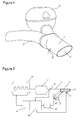
- a profile of the amplitude of the control signal output to the loudspeaker 12 by the anti-sound control 10 which builds up in an oscillating manner is shown in the upper part of Fig. 6 for the time to the right of the point of time B.
- the anti-sound control 10 in another operating mode is further designed to determine the rotational speed of the combustion engine 6 in sound measured by the error microphone 5 through Fourier analysis. Reading out the rotational speed from the engine control 8 is therefore not required in this operating mode. Determining the engine rotational speed through Fourier analysis must thus be seen as alternative to step S4 in Figure 5 . The remaining setup of Figure 5 remains unchanged. In the same manner, the torque of the combustion engine 6 can also be determined through Fourier analysis.
Applications Claiming Priority (1)
| Application Number | Priority Date | Filing Date | Title |
|---|---|---|---|
| DE102011103211 | 2011-06-01 |
Publications (2)
| Publication Number | Publication Date |
|---|---|
| EP2530263A1 true EP2530263A1 (fr) | 2012-12-05 |
| EP2530263B1 EP2530263B1 (fr) | 2013-08-21 |
Family
ID=46201433
Family Applications (1)
| Application Number | Title | Priority Date | Filing Date |
|---|---|---|---|
| EP12170274.0A Revoked EP2530263B1 (fr) | 2011-06-01 | 2012-05-31 | Système de commande active du bruit pour systèmes d'échappement et procédé de commande associé |
Country Status (5)
| Country | Link |
|---|---|
| US (1) | US9025786B2 (fr) |
| EP (1) | EP2530263B1 (fr) |
| JP (1) | JP5507616B2 (fr) |
| CN (1) | CN102808681B (fr) |
| DE (1) | DE202012012724U1 (fr) |
Cited By (3)
| Publication number | Priority date | Publication date | Assignee | Title |
|---|---|---|---|---|
| WO2016062602A1 (fr) * | 2014-10-21 | 2016-04-28 | Thyssenkrupp Marine Systems Gmbh | Sous-marin |
| US9706295B2 (en) | 2013-06-25 | 2017-07-11 | Eberspächer Exhaust Technology GmbH & Co. KG | System for influencing exhaust noise in a multi-flow exhaust system |
| WO2018234212A1 (fr) * | 2017-06-23 | 2018-12-27 | Tenneco Gmbh | Haut-parleur variable pour un système d'échappement |
Families Citing this family (15)
| Publication number | Priority date | Publication date | Assignee | Title |
|---|---|---|---|---|
| DE102012024615A1 (de) * | 2012-12-17 | 2014-06-18 | GM Global Technology Operations LLC (n. d. Gesetzen des Staates Delaware) | Vorrichtung zur Beeinflussung des Kabinengeräuschs |
| US9269344B2 (en) * | 2013-09-03 | 2016-02-23 | Bose Corporation | Engine harmonic cancellation system afterglow mitigation |
| DE102013217849A1 (de) * | 2013-09-06 | 2015-03-12 | Friedrich Boysen Gmbh & Co. Kg | Aktive Schallerzeugungseinrichtung |
| EP2871639B1 (fr) * | 2013-11-08 | 2019-04-17 | Volvo Car Corporation | Procédé et système de masquage acoustique |
| DE102013113803A1 (de) * | 2013-12-10 | 2015-06-11 | Eberspächer Exhaust Technology GmbH & Co. KG | Schallerzeuger für ein System zur Beeinflussung von Abgasgeräuschen eines Kraftfahrzeugs |
| CN104712405A (zh) * | 2013-12-13 | 2015-06-17 | 上海通用汽车有限公司 | 混合动力车型的进排气系统 |
| CN104775884B (zh) * | 2014-01-09 | 2019-11-08 | 罗伯特·博世有限公司 | 用于运行内燃机的方法和装置 |
| US9394812B2 (en) * | 2014-07-09 | 2016-07-19 | Aai Corporation | Attenuating engine noise using a reverse resonator |
| DE102014113940A1 (de) * | 2014-09-25 | 2016-03-31 | Eberspächer Exhaust Technology GmbH & Co. KG | Überlastungsschutz für einen Aktor eines Systems zur Beeinflussung von in einer Abgasanlage geführtem Schall |
| KR101755463B1 (ko) | 2015-06-18 | 2017-07-07 | 현대자동차 주식회사 | 차량 연소음 마스킹 제어 장치 및 방법 |
| TWI567292B (zh) * | 2016-03-16 | 2017-01-21 | 中原大學 | 具消除噪音與調整噪音頻率功能的排氣裝置 |
| WO2018111233A1 (fr) | 2016-12-13 | 2018-06-21 | Halliburton Energy Services, Inc. | Réduction du bruit de champ lointain produit par des opérations de puits |
| WO2018125116A1 (fr) | 2016-12-29 | 2018-07-05 | Halliburton Energy Services, Inc. | Commande de bruit active pour équipement de fracturation hydraulique |
| US10724410B1 (en) | 2017-11-14 | 2020-07-28 | Brunswick Corporation | Exhaust sound enhancement assembly and method for a marine propulsion device |
| US10699693B1 (en) * | 2019-07-08 | 2020-06-30 | Hyundai Motor Company | Sound generator for vehicle |
Citations (19)
| Publication number | Priority date | Publication date | Assignee | Title |
|---|---|---|---|---|
| US4177874A (en) | 1977-04-01 | 1979-12-11 | Agence Nationale De Valorisation De La Recherche (Anvar) | Active acoustic sound absorber device |
| EP0373188A1 (fr) | 1988-02-19 | 1990-06-20 | Noise Cancellation Tech | Dispositif de silencieux de gas d'echappement pour moteur a combustion interne. |
| US5229556A (en) | 1990-04-25 | 1993-07-20 | Ford Motor Company | Internal ported band pass enclosure for sound cancellation |
| US5233137A (en) | 1990-04-25 | 1993-08-03 | Ford Motor Company | Protective anc loudspeaker membrane |
| US5336856A (en) | 1992-07-07 | 1994-08-09 | Arvin Industries, Inc. | Electronic muffler assembly with exhaust bypass |
| US5343533A (en) | 1992-04-06 | 1994-08-30 | Ford Motor Company | Transducer flux optimization |
| US5432857A (en) | 1990-04-25 | 1995-07-11 | Ford Motor Company | Dual bandpass secondary source |
| EP0674097A1 (fr) | 1994-02-22 | 1995-09-27 | ELECTRONIC SOUND ATTENUATION S.p.A. | Silencieux actif de gaz d'échappement |
| EP0755045A2 (fr) | 1995-07-20 | 1997-01-22 | NOKIA TECHNOLOGY GmbH | Dispositif de suppression d'ondes sonores |
| US5600106A (en) | 1994-05-24 | 1997-02-04 | Noise Cancellation Technologies, Inc. | Actively sound reduced muffler having a venturi effect configuration |
| US5619020A (en) | 1991-08-29 | 1997-04-08 | Noise Cancellation Technologies, Inc. | Muffler |
| EP0916817A2 (fr) | 1997-11-18 | 1999-05-19 | LEISTRITZ AG & CO. Abgastechnik | Silencieux actif |
| DE19751596A1 (de) | 1997-11-21 | 1999-06-02 | Leistritz Abgastech | Aktiver Schalldämpfer |
| EP1055804A1 (fr) | 1999-05-19 | 2000-11-29 | LEISTRITZ AG & CO. Abgastechnik | Amortisseur actif de bruit de gaz d'échappement |
| EP1627996A1 (fr) | 2004-08-19 | 2006-02-22 | J. Eberspächer GmbH & Co. KG | Silencieux d'échappement actif |
| DE102006042224B3 (de) | 2006-09-06 | 2008-01-17 | J. Eberspächer GmbH & Co. KG | Aktiver Schalldämpfer für eine Abgasanlage |
| EP2072769A1 (fr) * | 2007-12-21 | 2009-06-24 | Robert Bosch Gmbh | Dispositif et procédé pour l'annulation active de bruit dans un canal de gaz d'échappement d'un moteur à combustion |
| DE102008018085A1 (de) | 2008-04-09 | 2009-10-15 | J. Eberspächer GmbH & Co. KG | Aktiver Schalldämpfer |
| DE102009031848A1 (de) | 2009-07-03 | 2011-01-05 | J. Eberspächer GmbH & Co. KG | Abgasanlage mit aktivem Schalldämpfer |
Family Cites Families (20)
| Publication number | Priority date | Publication date | Assignee | Title |
|---|---|---|---|---|
| US5022082A (en) | 1990-01-12 | 1991-06-04 | Nelson Industries, Inc. | Active acoustic attenuation system with reduced convergence time |
| DE4033269A1 (de) | 1990-10-19 | 1992-04-23 | Gillet Heinrich Gmbh | Schalldaempferanlage fuer kraftfahrzeuge |
| JP2789883B2 (ja) | 1991-09-30 | 1998-08-27 | 日産自動車株式会社 | 吸気管又は排気管の騒音低減装置 |
| JP3016972B2 (ja) | 1992-09-03 | 2000-03-06 | パロマ工業株式会社 | パルス燃焼器 |
| US5325438A (en) | 1993-02-01 | 1994-06-28 | At&T Bell Laboratories | Active noise-cancellation system for automotive mufflers |
| JPH07189645A (ja) * | 1993-12-27 | 1995-07-28 | Futaba Sangyo Kk | アクティブ消音装置 |
| JPH08158966A (ja) | 1994-11-30 | 1996-06-18 | Nippondenso Co Ltd | 内燃機関の騒音制御装置 |
| JP3250001B2 (ja) | 1995-06-09 | 2002-01-28 | 株式会社クボタ | 包囲型エンジンの騒音低減装置 |
| DE19645202B4 (de) | 1995-12-23 | 2006-05-11 | Volkswagen Ag | Verfahren zur Überwachung der Konvertierungsrate eines Abgaskatalysators für eine Brennkraftmaschine |
| JPH1011076A (ja) | 1996-06-19 | 1998-01-16 | Toa Corp | 電子消音装置 |
| JPH10238339A (ja) | 1997-02-20 | 1998-09-08 | Nissan Motor Co Ltd | エンジンの排気浄化装置 |
| DE19713182A1 (de) | 1997-03-27 | 1998-10-01 | Siemens Ag | Verfahren und Vorrichtung zur Bestimmung der Motordrehzahl eines Kraftfahrzeuges |
| JP4125851B2 (ja) | 2000-03-30 | 2008-07-30 | ティーオーエー株式会社 | 能動型消音装置 |
| DE10201465B4 (de) | 2002-01-16 | 2004-02-19 | Bayerische Motoren Werke Ag | Verfahren und Vorrichtung zum Steuern einer Bauteilschutzfunktion |
| US7059820B2 (en) | 2002-07-19 | 2006-06-13 | Honeywell International, Inc. | Noise control |
| DE10316946A1 (de) | 2003-04-12 | 2004-10-21 | Daimlerchrysler Ag | Vorrichtung und Verfahren zur Dämpfung von Druckschwingungen in Hydraulikleitungen |
| DE102005019459B3 (de) | 2005-04-25 | 2006-07-13 | Benteler Automobiltechnik Gmbh | Aktiver Ansaugschalldämpfer |
| US20090058633A1 (en) | 2007-08-31 | 2009-03-05 | Matsushita Electric Industrial Co., Ltd. | Anc notch filter adaptation system and method for handling road noise peak shifts in a motor vehicle |
| US7753165B2 (en) * | 2007-12-21 | 2010-07-13 | Robert Bosch Gmbh | Device and method for active noise cancellation in exhaust gas channel of a combustion engine |
| DE102009012092A1 (de) | 2009-03-06 | 2010-09-09 | Man Nutzfahrzeuge Ag | Verfahren zur Anpassung der Dosiermenge eines Reduktionsmittels zur selektiven katalytischen Reduktion |
-
2012
- 2012-05-31 DE DE202012012724U patent/DE202012012724U1/de not_active Expired - Lifetime
- 2012-05-31 US US13/485,520 patent/US9025786B2/en active Active
- 2012-05-31 EP EP12170274.0A patent/EP2530263B1/fr not_active Revoked
- 2012-06-01 CN CN201210249156.4A patent/CN102808681B/zh active Active
- 2012-06-01 JP JP2012125787A patent/JP5507616B2/ja active Active
Patent Citations (19)
| Publication number | Priority date | Publication date | Assignee | Title |
|---|---|---|---|---|
| US4177874A (en) | 1977-04-01 | 1979-12-11 | Agence Nationale De Valorisation De La Recherche (Anvar) | Active acoustic sound absorber device |
| EP0373188A1 (fr) | 1988-02-19 | 1990-06-20 | Noise Cancellation Tech | Dispositif de silencieux de gas d'echappement pour moteur a combustion interne. |
| US5229556A (en) | 1990-04-25 | 1993-07-20 | Ford Motor Company | Internal ported band pass enclosure for sound cancellation |
| US5233137A (en) | 1990-04-25 | 1993-08-03 | Ford Motor Company | Protective anc loudspeaker membrane |
| US5432857A (en) | 1990-04-25 | 1995-07-11 | Ford Motor Company | Dual bandpass secondary source |
| US5619020A (en) | 1991-08-29 | 1997-04-08 | Noise Cancellation Technologies, Inc. | Muffler |
| US5343533A (en) | 1992-04-06 | 1994-08-30 | Ford Motor Company | Transducer flux optimization |
| US5336856A (en) | 1992-07-07 | 1994-08-09 | Arvin Industries, Inc. | Electronic muffler assembly with exhaust bypass |
| EP0674097A1 (fr) | 1994-02-22 | 1995-09-27 | ELECTRONIC SOUND ATTENUATION S.p.A. | Silencieux actif de gaz d'échappement |
| US5600106A (en) | 1994-05-24 | 1997-02-04 | Noise Cancellation Technologies, Inc. | Actively sound reduced muffler having a venturi effect configuration |
| EP0755045A2 (fr) | 1995-07-20 | 1997-01-22 | NOKIA TECHNOLOGY GmbH | Dispositif de suppression d'ondes sonores |
| EP0916817A2 (fr) | 1997-11-18 | 1999-05-19 | LEISTRITZ AG & CO. Abgastechnik | Silencieux actif |
| DE19751596A1 (de) | 1997-11-21 | 1999-06-02 | Leistritz Abgastech | Aktiver Schalldämpfer |
| EP1055804A1 (fr) | 1999-05-19 | 2000-11-29 | LEISTRITZ AG & CO. Abgastechnik | Amortisseur actif de bruit de gaz d'échappement |
| EP1627996A1 (fr) | 2004-08-19 | 2006-02-22 | J. Eberspächer GmbH & Co. KG | Silencieux d'échappement actif |
| DE102006042224B3 (de) | 2006-09-06 | 2008-01-17 | J. Eberspächer GmbH & Co. KG | Aktiver Schalldämpfer für eine Abgasanlage |
| EP2072769A1 (fr) * | 2007-12-21 | 2009-06-24 | Robert Bosch Gmbh | Dispositif et procédé pour l'annulation active de bruit dans un canal de gaz d'échappement d'un moteur à combustion |
| DE102008018085A1 (de) | 2008-04-09 | 2009-10-15 | J. Eberspächer GmbH & Co. KG | Aktiver Schalldämpfer |
| DE102009031848A1 (de) | 2009-07-03 | 2011-01-05 | J. Eberspächer GmbH & Co. KG | Abgasanlage mit aktivem Schalldämpfer |
Cited By (3)
| Publication number | Priority date | Publication date | Assignee | Title |
|---|---|---|---|---|
| US9706295B2 (en) | 2013-06-25 | 2017-07-11 | Eberspächer Exhaust Technology GmbH & Co. KG | System for influencing exhaust noise in a multi-flow exhaust system |
| WO2016062602A1 (fr) * | 2014-10-21 | 2016-04-28 | Thyssenkrupp Marine Systems Gmbh | Sous-marin |
| WO2018234212A1 (fr) * | 2017-06-23 | 2018-12-27 | Tenneco Gmbh | Haut-parleur variable pour un système d'échappement |
Also Published As
| Publication number | Publication date |
|---|---|
| CN102808681B (zh) | 2015-04-22 |
| DE202012012724U1 (de) | 2013-09-11 |
| US9025786B2 (en) | 2015-05-05 |
| EP2530263B1 (fr) | 2013-08-21 |
| CN102808681A (zh) | 2012-12-05 |
| US20120308023A1 (en) | 2012-12-06 |
| JP2012251554A (ja) | 2012-12-20 |
| JP5507616B2 (ja) | 2014-05-28 |
Similar Documents
| Publication | Publication Date | Title |
|---|---|---|
| EP2530263B1 (fr) | Système de commande active du bruit pour systèmes d'échappement et procédé de commande associé | |
| EP2590163B1 (fr) | Protection contre les surcharges pour haut-parleurs dans des systèmes d'échappement | |
| EP2543835B1 (fr) | Système anti-son pour systèmes d'échappement et procédé pour le commander | |
| US7753165B2 (en) | Device and method for active noise cancellation in exhaust gas channel of a combustion engine | |
| US9970340B2 (en) | Vehicle exhaust system with resonance damping | |
| US5655367A (en) | Inlet or exhaust line for a reciprocating machine | |
| US9706295B2 (en) | System for influencing exhaust noise in a multi-flow exhaust system | |
| US8434590B2 (en) | Muffler | |
| CN104895648A (zh) | 排气噪音的有源设计 | |
| US20140321659A1 (en) | System for influencing exhaust noise, engine noise and/or intake noise | |
| JP2015048845A (ja) | 凝縮物を除去するためのシステムを有する排気系 | |
| US10215067B2 (en) | Overload protection for an actuator of a system for controlling sound propagating through an exhaust system | |
| JP2009257326A (ja) | 内燃機関の排気チャネルにおける能動ノイズキャンセルのための装置および方法 | |
| JP2007510094A (ja) | 排気物質の低減のためのエンジン制御システム | |
| JPH07319481A (ja) | 電子消音装置 | |
| KR20120044629A (ko) | 온도보상이 가능한 공명형 소음저감장치 | |
| Bay et al. | Compact silencer for heating systems | |
| JP2006258003A (ja) | アクティブ消音装置 | |
| JP2013170546A (ja) | 消音装置 | |
| KR980009779A (ko) | 자동차용 배기장치의 머플러 | |
| JPH04132814A (ja) | 変動周波数対応消音装置 | |
| KR19980076062A (ko) | 배기소음 제어장치 | |
| KR19980027381U (ko) | 가변식 자동차용 소음저감장치 |
Legal Events
| Date | Code | Title | Description |
|---|---|---|---|
| REG | Reference to a national code |
Ref country code: DE Ref legal event code: R138 Ref document number: 602012000221 Country of ref document: DE Free format text: GERMAN DOCUMENT NUMBER IS 602012000221 Ref country code: DE Ref legal event code: R138 Ref document number: 202012012724 Country of ref document: DE Free format text: GERMAN DOCUMENT NUMBER IS 602012000221 |
|
| PUAI | Public reference made under article 153(3) epc to a published international application that has entered the european phase |
Free format text: ORIGINAL CODE: 0009012 |
|
| 17P | Request for examination filed |
Effective date: 20120822 |
|
| AK | Designated contracting states |
Kind code of ref document: A1 Designated state(s): AL AT BE BG CH CY CZ DE DK EE ES FI FR GB GR HR HU IE IS IT LI LT LU LV MC MK MT NL NO PL PT RO RS SE SI SK SM TR |
|
| AX | Request for extension of the european patent |
Extension state: BA ME |
|
| GRAP | Despatch of communication of intention to grant a patent |
Free format text: ORIGINAL CODE: EPIDOSNIGR1 |
|
| GRAS | Grant fee paid |
Free format text: ORIGINAL CODE: EPIDOSNIGR3 |
|
| GRAA | (expected) grant |
Free format text: ORIGINAL CODE: 0009210 |
|
| RAP1 | Party data changed (applicant data changed or rights of an application transferred) |
Owner name: EBERSPAECHER EXHAUST TECHNOLOGY GMBH & CO. KG |
|
| AK | Designated contracting states |
Kind code of ref document: B1 Designated state(s): AL AT BE BG CH CY CZ DE DK EE ES FI FR GB GR HR HU IE IS IT LI LT LU LV MC MK MT NL NO PL PT RO RS SE SI SK SM TR |
|
| REG | Reference to a national code |
Ref country code: GB Ref legal event code: FG4D |
|
| REG | Reference to a national code |
Ref country code: CH Ref legal event code: EP |
|
| REG | Reference to a national code |
Ref country code: AT Ref legal event code: REF Ref document number: 628241 Country of ref document: AT Kind code of ref document: T Effective date: 20130915 |
|
| REG | Reference to a national code |
Ref country code: IE Ref legal event code: FG4D |
|
| REG | Reference to a national code |
Ref country code: DE Ref legal event code: R096 Ref document number: 602012000221 Country of ref document: DE Effective date: 20131017 |
|
| REG | Reference to a national code |
Ref country code: AT Ref legal event code: MK05 Ref document number: 628241 Country of ref document: AT Kind code of ref document: T Effective date: 20130821 Ref country code: NL Ref legal event code: VDEP Effective date: 20130821 |
|
| REG | Reference to a national code |
Ref country code: LT Ref legal event code: MG4D |
|
| PG25 | Lapsed in a contracting state [announced via postgrant information from national office to epo] |
Ref country code: HR Free format text: LAPSE BECAUSE OF FAILURE TO SUBMIT A TRANSLATION OF THE DESCRIPTION OR TO PAY THE FEE WITHIN THE PRESCRIBED TIME-LIMIT Effective date: 20130821 Ref country code: PT Free format text: LAPSE BECAUSE OF FAILURE TO SUBMIT A TRANSLATION OF THE DESCRIPTION OR TO PAY THE FEE WITHIN THE PRESCRIBED TIME-LIMIT Effective date: 20131223 Ref country code: NO Free format text: LAPSE BECAUSE OF FAILURE TO SUBMIT A TRANSLATION OF THE DESCRIPTION OR TO PAY THE FEE WITHIN THE PRESCRIBED TIME-LIMIT Effective date: 20131121 Ref country code: IS Free format text: LAPSE BECAUSE OF FAILURE TO SUBMIT A TRANSLATION OF THE DESCRIPTION OR TO PAY THE FEE WITHIN THE PRESCRIBED TIME-LIMIT Effective date: 20131221 Ref country code: CY Free format text: LAPSE BECAUSE OF FAILURE TO SUBMIT A TRANSLATION OF THE DESCRIPTION OR TO PAY THE FEE WITHIN THE PRESCRIBED TIME-LIMIT Effective date: 20130918 Ref country code: LT Free format text: LAPSE BECAUSE OF FAILURE TO SUBMIT A TRANSLATION OF THE DESCRIPTION OR TO PAY THE FEE WITHIN THE PRESCRIBED TIME-LIMIT Effective date: 20130821 Ref country code: SE Free format text: LAPSE BECAUSE OF FAILURE TO SUBMIT A TRANSLATION OF THE DESCRIPTION OR TO PAY THE FEE WITHIN THE PRESCRIBED TIME-LIMIT Effective date: 20130821 Ref country code: AT Free format text: LAPSE BECAUSE OF FAILURE TO SUBMIT A TRANSLATION OF THE DESCRIPTION OR TO PAY THE FEE WITHIN THE PRESCRIBED TIME-LIMIT Effective date: 20130821 |
|
| PG25 | Lapsed in a contracting state [announced via postgrant information from national office to epo] |
Ref country code: PL Free format text: LAPSE BECAUSE OF FAILURE TO SUBMIT A TRANSLATION OF THE DESCRIPTION OR TO PAY THE FEE WITHIN THE PRESCRIBED TIME-LIMIT Effective date: 20130821 Ref country code: BE Free format text: LAPSE BECAUSE OF FAILURE TO SUBMIT A TRANSLATION OF THE DESCRIPTION OR TO PAY THE FEE WITHIN THE PRESCRIBED TIME-LIMIT Effective date: 20130821 Ref country code: LV Free format text: LAPSE BECAUSE OF FAILURE TO SUBMIT A TRANSLATION OF THE DESCRIPTION OR TO PAY THE FEE WITHIN THE PRESCRIBED TIME-LIMIT Effective date: 20130821 Ref country code: FI Free format text: LAPSE BECAUSE OF FAILURE TO SUBMIT A TRANSLATION OF THE DESCRIPTION OR TO PAY THE FEE WITHIN THE PRESCRIBED TIME-LIMIT Effective date: 20130821 Ref country code: GR Free format text: LAPSE BECAUSE OF FAILURE TO SUBMIT A TRANSLATION OF THE DESCRIPTION OR TO PAY THE FEE WITHIN THE PRESCRIBED TIME-LIMIT Effective date: 20131122 |
|
| PG25 | Lapsed in a contracting state [announced via postgrant information from national office to epo] |
Ref country code: CY Free format text: LAPSE BECAUSE OF FAILURE TO SUBMIT A TRANSLATION OF THE DESCRIPTION OR TO PAY THE FEE WITHIN THE PRESCRIBED TIME-LIMIT Effective date: 20130821 |
|
| PG25 | Lapsed in a contracting state [announced via postgrant information from national office to epo] |
Ref country code: DK Free format text: LAPSE BECAUSE OF FAILURE TO SUBMIT A TRANSLATION OF THE DESCRIPTION OR TO PAY THE FEE WITHIN THE PRESCRIBED TIME-LIMIT Effective date: 20130821 Ref country code: EE Free format text: LAPSE BECAUSE OF FAILURE TO SUBMIT A TRANSLATION OF THE DESCRIPTION OR TO PAY THE FEE WITHIN THE PRESCRIBED TIME-LIMIT Effective date: 20130821 Ref country code: NL Free format text: LAPSE BECAUSE OF FAILURE TO SUBMIT A TRANSLATION OF THE DESCRIPTION OR TO PAY THE FEE WITHIN THE PRESCRIBED TIME-LIMIT Effective date: 20130821 Ref country code: CZ Free format text: LAPSE BECAUSE OF FAILURE TO SUBMIT A TRANSLATION OF THE DESCRIPTION OR TO PAY THE FEE WITHIN THE PRESCRIBED TIME-LIMIT Effective date: 20130821 Ref country code: SK Free format text: LAPSE BECAUSE OF FAILURE TO SUBMIT A TRANSLATION OF THE DESCRIPTION OR TO PAY THE FEE WITHIN THE PRESCRIBED TIME-LIMIT Effective date: 20130821 Ref country code: RO Free format text: LAPSE BECAUSE OF FAILURE TO SUBMIT A TRANSLATION OF THE DESCRIPTION OR TO PAY THE FEE WITHIN THE PRESCRIBED TIME-LIMIT Effective date: 20130821 |
|
| PG25 | Lapsed in a contracting state [announced via postgrant information from national office to epo] |
Ref country code: ES Free format text: LAPSE BECAUSE OF FAILURE TO SUBMIT A TRANSLATION OF THE DESCRIPTION OR TO PAY THE FEE WITHIN THE PRESCRIBED TIME-LIMIT Effective date: 20130821 |
|
| PLBI | Opposition filed |
Free format text: ORIGINAL CODE: 0009260 |
|
| PLAX | Notice of opposition and request to file observation + time limit sent |
Free format text: ORIGINAL CODE: EPIDOSNOBS2 |
|
| 26 | Opposition filed |
Opponent name: TENNECO GMBH Effective date: 20140521 Opponent name: FAURECIA EMISSIONS CONTROL TECHNOLOGIES, GERMANY G Effective date: 20140521 |
|
| REG | Reference to a national code |
Ref country code: DE Ref legal event code: R026 Ref document number: 602012000221 Country of ref document: DE Effective date: 20140521 |
|
| PLBB | Reply of patent proprietor to notice(s) of opposition received |
Free format text: ORIGINAL CODE: EPIDOSNOBS3 |
|
| PG25 | Lapsed in a contracting state [announced via postgrant information from national office to epo] |
Ref country code: LU Free format text: LAPSE BECAUSE OF FAILURE TO SUBMIT A TRANSLATION OF THE DESCRIPTION OR TO PAY THE FEE WITHIN THE PRESCRIBED TIME-LIMIT Effective date: 20140531 |
|
| PG25 | Lapsed in a contracting state [announced via postgrant information from national office to epo] |
Ref country code: MC Free format text: LAPSE BECAUSE OF FAILURE TO SUBMIT A TRANSLATION OF THE DESCRIPTION OR TO PAY THE FEE WITHIN THE PRESCRIBED TIME-LIMIT Effective date: 20130821 |
|
| REG | Reference to a national code |
Ref country code: IE Ref legal event code: MM4A |
|
| PG25 | Lapsed in a contracting state [announced via postgrant information from national office to epo] |
Ref country code: IE Free format text: LAPSE BECAUSE OF NON-PAYMENT OF DUE FEES Effective date: 20140531 |
|
| REG | Reference to a national code |
Ref country code: FR Ref legal event code: PLFP Year of fee payment: 4 |
|
| PLAY | Examination report in opposition despatched + time limit |
Free format text: ORIGINAL CODE: EPIDOSNORE2 |
|
| PLBC | Reply to examination report in opposition received |
Free format text: ORIGINAL CODE: EPIDOSNORE3 |
|
| REG | Reference to a national code |
Ref country code: CH Ref legal event code: PL |
|
| PG25 | Lapsed in a contracting state [announced via postgrant information from national office to epo] |
Ref country code: LI Free format text: LAPSE BECAUSE OF NON-PAYMENT OF DUE FEES Effective date: 20150531 Ref country code: CH Free format text: LAPSE BECAUSE OF NON-PAYMENT OF DUE FEES Effective date: 20150531 |
|
| PG25 | Lapsed in a contracting state [announced via postgrant information from national office to epo] |
Ref country code: MT Free format text: LAPSE BECAUSE OF FAILURE TO SUBMIT A TRANSLATION OF THE DESCRIPTION OR TO PAY THE FEE WITHIN THE PRESCRIBED TIME-LIMIT Effective date: 20130821 |
|
| PG25 | Lapsed in a contracting state [announced via postgrant information from national office to epo] |
Ref country code: SM Free format text: LAPSE BECAUSE OF FAILURE TO SUBMIT A TRANSLATION OF THE DESCRIPTION OR TO PAY THE FEE WITHIN THE PRESCRIBED TIME-LIMIT Effective date: 20130821 |
|
| REG | Reference to a national code |
Ref country code: FR Ref legal event code: PLFP Year of fee payment: 5 |
|
| REG | Reference to a national code |
Ref country code: DE Ref legal event code: R064 Ref document number: 602012000221 Country of ref document: DE Ref country code: DE Ref legal event code: R103 Ref document number: 602012000221 Country of ref document: DE |
|
| RDAF | Communication despatched that patent is revoked |
Free format text: ORIGINAL CODE: EPIDOSNREV1 |
|
| PG25 | Lapsed in a contracting state [announced via postgrant information from national office to epo] |
Ref country code: BG Free format text: LAPSE BECAUSE OF FAILURE TO SUBMIT A TRANSLATION OF THE DESCRIPTION OR TO PAY THE FEE WITHIN THE PRESCRIBED TIME-LIMIT Effective date: 20130821 Ref country code: RS Free format text: LAPSE BECAUSE OF NON-PAYMENT OF DUE FEES Effective date: 20130821 |
|
| PG25 | Lapsed in a contracting state [announced via postgrant information from national office to epo] |
Ref country code: HU Free format text: LAPSE BECAUSE OF FAILURE TO SUBMIT A TRANSLATION OF THE DESCRIPTION OR TO PAY THE FEE WITHIN THE PRESCRIBED TIME-LIMIT; INVALID AB INITIO Effective date: 20120531 Ref country code: TR Free format text: LAPSE BECAUSE OF FAILURE TO SUBMIT A TRANSLATION OF THE DESCRIPTION OR TO PAY THE FEE WITHIN THE PRESCRIBED TIME-LIMIT Effective date: 20130821 Ref country code: SI Free format text: LAPSE BECAUSE OF FAILURE TO SUBMIT A TRANSLATION OF THE DESCRIPTION OR TO PAY THE FEE WITHIN THE PRESCRIBED TIME-LIMIT Effective date: 20130821 |
|
| PGFP | Annual fee paid to national office [announced via postgrant information from national office to epo] |
Ref country code: GB Payment date: 20160523 Year of fee payment: 5 Ref country code: DE Payment date: 20160525 Year of fee payment: 5 |
|
| PGFP | Annual fee paid to national office [announced via postgrant information from national office to epo] |
Ref country code: FR Payment date: 20160523 Year of fee payment: 5 Ref country code: IT Payment date: 20160524 Year of fee payment: 5 |
|
| RDAG | Patent revoked |
Free format text: ORIGINAL CODE: 0009271 |
|
| STAA | Information on the status of an ep patent application or granted ep patent |
Free format text: STATUS: PATENT REVOKED |
|
| 27W | Patent revoked |
Effective date: 20160601 |
|
| GBPR | Gb: patent revoked under art. 102 of the ep convention designating the uk as contracting state |
Effective date: 20160601 |
|
| PG25 | Lapsed in a contracting state [announced via postgrant information from national office to epo] |
Ref country code: AL Free format text: LAPSE BECAUSE OF FAILURE TO SUBMIT A TRANSLATION OF THE DESCRIPTION OR TO PAY THE FEE WITHIN THE PRESCRIBED TIME-LIMIT Effective date: 20130821 |