EP2530263A1 - Active noise control system for exhaust systems and method for controlling the same - Google Patents
Active noise control system for exhaust systems and method for controlling the same Download PDFInfo
- Publication number
- EP2530263A1 EP2530263A1 EP12170274A EP12170274A EP2530263A1 EP 2530263 A1 EP2530263 A1 EP 2530263A1 EP 12170274 A EP12170274 A EP 12170274A EP 12170274 A EP12170274 A EP 12170274A EP 2530263 A1 EP2530263 A1 EP 2530263A1
- Authority
- EP
- European Patent Office
- Prior art keywords
- sound
- control
- exhaust system
- exhaust
- combustion engine
- Prior art date
- Legal status (The legal status is an assumption and is not a legal conclusion. Google has not performed a legal analysis and makes no representation as to the accuracy of the status listed.)
- Granted
Links
Images


Classifications
-
- F—MECHANICAL ENGINEERING; LIGHTING; HEATING; WEAPONS; BLASTING
- F01—MACHINES OR ENGINES IN GENERAL; ENGINE PLANTS IN GENERAL; STEAM ENGINES
- F01N—GAS-FLOW SILENCERS OR EXHAUST APPARATUS FOR MACHINES OR ENGINES IN GENERAL; GAS-FLOW SILENCERS OR EXHAUST APPARATUS FOR INTERNAL COMBUSTION ENGINES
- F01N1/00—Silencing apparatus characterised by method of silencing
- F01N1/06—Silencing apparatus characterised by method of silencing by using interference effect
- F01N1/065—Silencing apparatus characterised by method of silencing by using interference effect by using an active noise source, e.g. speakers
-
- F—MECHANICAL ENGINEERING; LIGHTING; HEATING; WEAPONS; BLASTING
- F16—ENGINEERING ELEMENTS AND UNITS; GENERAL MEASURES FOR PRODUCING AND MAINTAINING EFFECTIVE FUNCTIONING OF MACHINES OR INSTALLATIONS; THERMAL INSULATION IN GENERAL
- F16L—PIPES; JOINTS OR FITTINGS FOR PIPES; SUPPORTS FOR PIPES, CABLES OR PROTECTIVE TUBING; MEANS FOR THERMAL INSULATION IN GENERAL
- F16L55/00—Devices or appurtenances for use in, or in connection with, pipes or pipe systems
- F16L55/02—Energy absorbers; Noise absorbers
- F16L55/033—Noise absorbers
- F16L55/0333—Noise absorbers by means of an active system
-
- G—PHYSICS
- G10—MUSICAL INSTRUMENTS; ACOUSTICS
- G10K—SOUND-PRODUCING DEVICES; METHODS OR DEVICES FOR PROTECTING AGAINST, OR FOR DAMPING, NOISE OR OTHER ACOUSTIC WAVES IN GENERAL; ACOUSTICS NOT OTHERWISE PROVIDED FOR
- G10K11/00—Methods or devices for transmitting, conducting or directing sound in general; Methods or devices for protecting against, or for damping, noise or other acoustic waves in general
- G10K11/16—Methods or devices for protecting against, or for damping, noise or other acoustic waves in general
- G10K11/175—Methods or devices for protecting against, or for damping, noise or other acoustic waves in general using interference effects; Masking sound
- G10K11/178—Methods or devices for protecting against, or for damping, noise or other acoustic waves in general using interference effects; Masking sound by electro-acoustically regenerating the original acoustic waves in anti-phase
- G10K11/1781—Methods or devices for protecting against, or for damping, noise or other acoustic waves in general using interference effects; Masking sound by electro-acoustically regenerating the original acoustic waves in anti-phase characterised by the analysis of input or output signals, e.g. frequency range, modes, transfer functions
- G10K11/17821—Methods or devices for protecting against, or for damping, noise or other acoustic waves in general using interference effects; Masking sound by electro-acoustically regenerating the original acoustic waves in anti-phase characterised by the analysis of input or output signals, e.g. frequency range, modes, transfer functions characterised by the analysis of the input signals only
-
- G—PHYSICS
- G10—MUSICAL INSTRUMENTS; ACOUSTICS
- G10K—SOUND-PRODUCING DEVICES; METHODS OR DEVICES FOR PROTECTING AGAINST, OR FOR DAMPING, NOISE OR OTHER ACOUSTIC WAVES IN GENERAL; ACOUSTICS NOT OTHERWISE PROVIDED FOR
- G10K11/00—Methods or devices for transmitting, conducting or directing sound in general; Methods or devices for protecting against, or for damping, noise or other acoustic waves in general
- G10K11/16—Methods or devices for protecting against, or for damping, noise or other acoustic waves in general
- G10K11/175—Methods or devices for protecting against, or for damping, noise or other acoustic waves in general using interference effects; Masking sound
- G10K11/178—Methods or devices for protecting against, or for damping, noise or other acoustic waves in general using interference effects; Masking sound by electro-acoustically regenerating the original acoustic waves in anti-phase
- G10K11/1787—General system configurations
- G10K11/17879—General system configurations using both a reference signal and an error signal
- G10K11/17883—General system configurations using both a reference signal and an error signal the reference signal being derived from a machine operating condition, e.g. engine RPM or vehicle speed
-
- F—MECHANICAL ENGINEERING; LIGHTING; HEATING; WEAPONS; BLASTING
- F01—MACHINES OR ENGINES IN GENERAL; ENGINE PLANTS IN GENERAL; STEAM ENGINES
- F01N—GAS-FLOW SILENCERS OR EXHAUST APPARATUS FOR MACHINES OR ENGINES IN GENERAL; GAS-FLOW SILENCERS OR EXHAUST APPARATUS FOR INTERNAL COMBUSTION ENGINES
- F01N2390/00—Arrangements for controlling or regulating exhaust apparatus
-
- G—PHYSICS
- G10—MUSICAL INSTRUMENTS; ACOUSTICS
- G10K—SOUND-PRODUCING DEVICES; METHODS OR DEVICES FOR PROTECTING AGAINST, OR FOR DAMPING, NOISE OR OTHER ACOUSTIC WAVES IN GENERAL; ACOUSTICS NOT OTHERWISE PROVIDED FOR
- G10K2210/00—Details of active noise control [ANC] covered by G10K11/178 but not provided for in any of its subgroups
- G10K2210/10—Applications
- G10K2210/128—Vehicles
- G10K2210/1282—Automobiles
- G10K2210/12822—Exhaust pipes or mufflers
-
- G—PHYSICS
- G10—MUSICAL INSTRUMENTS; ACOUSTICS
- G10K—SOUND-PRODUCING DEVICES; METHODS OR DEVICES FOR PROTECTING AGAINST, OR FOR DAMPING, NOISE OR OTHER ACOUSTIC WAVES IN GENERAL; ACOUSTICS NOT OTHERWISE PROVIDED FOR
- G10K2210/00—Details of active noise control [ANC] covered by G10K11/178 but not provided for in any of its subgroups
- G10K2210/30—Means
- G10K2210/301—Computational
- G10K2210/3033—Information contained in memory, e.g. stored signals or transfer functions
Landscapes
- Engineering & Computer Science (AREA)
- General Engineering & Computer Science (AREA)
- Mechanical Engineering (AREA)
- Physics & Mathematics (AREA)
- Acoustics & Sound (AREA)
- Multimedia (AREA)
- Chemical & Material Sciences (AREA)
- Combustion & Propulsion (AREA)
- Exhaust Silencers (AREA)
- Soundproofing, Sound Blocking, And Sound Damping (AREA)
- Combined Controls Of Internal Combustion Engines (AREA)
Abstract
Description
- The present application claims priority of Patent Application No.
10 2011 103 211.1 in Germany, entitled "ANTI-SOUND SYSTEM FOR EXHAUST SYSTEMS AND METHOD FOR CONTROLLING THE SAME", the content of which is hereby incorporated by reference in its entirety. - The invention relates to an active noise control system for exhaust systems and a method for controlling the same. Thus, the present invention relates to at least one of an active cancellation and reduction and alteration of sound-waves in exhaust systems of combustion engine driven vehicles.
- Regardless of the design of a combustion engine (for example reciprocating engine, pistonless rotary engine or free-piston engine), noises are generated because of the working cycles (in particular sucking-in and compressing a fuel-air mixture, ignition/expansion and exhausting the combusted fuel-air mixture) taking place in succession. These noises on the one hand pass through the combustion engine as solid-borne sound and are radiated off the outside of the combustion engine as airborne sound. On the other hand, the noises pass through an exhaust system of the combustion engine as airborne sound together with the combusted fuel-air mixture.
- These noises are frequently perceived disadvantageous. On the one hand, there are legal stipulations for noise control, which have to be adhered to by manufacturers of vehicles driven by combustion engines. These legal stipulations as a rule specify a maximum permissible sound pressure during the operation of the vehicle. On the other hand, manufacturers attempt to impart a characteristic sound development on the combustion engine driven vehicles produced by them, which fit the image of the respective manufacturer and are to appeal to the customers. With modern engines including low cubic capacity, this characteristic noise development can frequently no longer be ensured in a natural way.
- The noises passing through the combustion engine as solid-borne sound can be dampened with high efficiency and therefore usually do not constitute a problem regarding noise control.
- The noises passing through an exhaust system of the combustion engine as airborne sound together with the combusted fuel-air mixture are conventionally reduced by silencers/mufflers arranged before the mouth of the exhaust system. If applicable, the silencers/mufflers are arranged downstream of existing catalytic converters. Such silencers/mufflers can for example operate according to the absorption and/or reflection principle. Silencers/mufflers constructed in accordance with either of these principles have the disadvantage that they require a comparatively large volume and put up a relatively high resistance to the combusted fuel-air mixture in case a high damping efficiency is required. Consequently, by using silencers/mufflers constructed in accordance with either of these principles the overall efficiency of the vehicle drops and the fuel consumption rises.
- As alternative or to complement silencers/mufflers, so-called active noise control systems have been in development for some time, which superimpose electro acoustically generated anti-sound (sound wave with the same amplitude but with inverted phase (antiphase) to the noise to be cancelled) on the airborne sound generated by the combustion engine and conducted in the exhaust system. Such systems are known for example from the documents
US 4,177,874 ,US 5,229,556 ,US 5,233,137 ,US 5,343,533 ,US 5,336,856 ,US 5,432,857 ,US 5,600,106 ,US 5,619,020 ,EP 0 373 188 ,EP 0 674 097EP 0 755 045EP 0 916 817EP 1 055 804EP 1 627 996 ,DE 197 51 596 ,DE 10 2006 042 224 ,DE 10 2008 018 085 ,DE 10 2009 031 848 . By using an active noise control system as alternative or to complement silencers/mufflers, the construction volume of an exhaust system can be reduced by up to 60%, the weight can be reduced by up to 40% and the exhaust back pressure can be reduced by up to 150 mbar. The term anti-sound serves to distinguish from the airborne sound (noise) conducted in the exhaust system. Considered on its own, anti-sound is conventional airborne sound with the same amplitude but with inverted phase to the original sound (noise) to be cancelled. - A corresponding active noise control system is shown in the
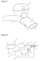
Figures 1 and 2 and can be procured from the company J. Eberspächer GmbH & Co. KG, Eberspächerstrasse 24, 73730 Esslingen, Germany. -
Figure 1 schematically shows a perspective view andFigure 2 a block diagram of an active noise control system connected to an exhaust line. - As is evident from
Figure 1 , both a sound generator 3' of an active noise control system as well as an exhaust pipe 4' fluidically connected to a combustion engine (in fluid communication with a combustion engine) lead into a tailpipe 1' in the region of an orifice 2' of an exhaust system. In the tailpipe 1', the airborne sound conducted in the exhaust pipe 4' together with the combusted fuel-air mixture is superimposed by anti-sound generated in the sound generator 3' of the active noise control system. To verify the effectiveness of the anti-sound, the tailpipe 1' comprises an error microphone 5'. - As is evident from
Figure 2 , a catalytic converter 7' is provided between the combustion engine 6' and the exhaust pipe 4'. In addition, a temperature probe 9' connected to an engine control 8' for determining the exhaust gas temperature is arranged in the exhaust pipe 4'. The engine control 8' is connected to the combustion engine 6'. In the engine control 8', an anti-sound control 10' is integrated, which is connected to the error microphone 5' of the tailpipe 1' and to a loudspeaker 12' belonging to the sound generator 3' via an amplifier 11'. - For achieving a destructive interference of the sound waves of the airborne sound conducted in the exhaust pipe 4' and of the anti-sound generated in the sound generator 3' in the region of the tailpipe 1', the sound waves in the tailpipe 1' originating from the sound generator 3' have to correspond in shape and amount, to the sound waves conducted in the exhaust pipe 4', but have a phase shift of 180 degrees (inverted phase) relative to these. For controlling the loudspeaker 12', the anti-sound control 10' makes use of empirically (experimentally) determined characteristic curves, which take into account the transmission distance between loudspeaker 12' of the sound generator 3' and the error microphone 5' in the tailpipe 1' and indicate the signal to be output to the loudspeaker 12' as a function of a rotational speed of the combustion engine 6' received from the engine control 8'. Since the propagation velocity of sound between loudspeaker 12' and error microphone 5' is temperature-dependent, the characteristic curves are also temperature-dependent and thus only suitable for a defined (nominal) temperature range. The selection of the characteristic curve applicable to a temperature range is made by the anti-sound control 10' by means of the value measured by the temperature sensor 9'.
- Thus, the anti-sound control 10' selects a characteristic curve that is suitable for this temperature range as a function of a value measured by the temperature sensor 9', from these characteristic curves, reads out values belonging to a respective engine rotational speed and by means of these values, outputs a corresponding signal to the loudspeaker 12' via the amplifier 11'. The success of the destructive sound wave superimposition is captured with the help of the error microphone 5'.
- In the case of known active noise control systems it is disadvantageous that the compensation of the temperature dependency of the speed of sound between loudspeaker and error microphone is complicated.
- Embodiments of the present invention provide an active noise control system for exhaust systems and a method for controlling the same, which allow a compensation of a temperature-dependency in a simple manner.
- Embodiments of an active noise control system for exhaust systems of a combustion engine-driven vehicle have an anti-sound control that can be connected to an engine control of the vehicle, and a loudspeaker, which is connected to the anti-sound control for receiving control signals. The connection between the anti-sound control and the loudspeaker can be provided for example by at least one of electrically and in sections via an air interface and in sections via a glass fibre. The loudspeaker is designed to generate anti-sound in a sound generator, which can be fluidically connected to the exhaust system (thus the internal space of the sound generator is in fluid communication with the internal space of the exhaust system). The sound generator can for example be a resonance chamber or a housing receiving the loudspeaker. The generation of the anti-sound by the loudspeaker is carried out as a function of a (in particular, electrical) control signal received by the anti-sound control. Here, an amplifier can be provided between the anti-sound control and the loudspeaker. In the anti-sound control, at least two characteristic curves are stored in order to at least partially and preferably completely cancel out in amount and phase airborne sound conducted in the exhaust system by generating anti-sound as a consequence of a control signal output to the loudspeaker. The characteristic curves stored in the anti-sound control cover different (nominal) temperature ranges of the exhaust gas conducted in the exhaust system. These temperature ranges overlap each other by pairs or immediately adjoin one another. By means of signals output by the engine control the anti-sound control selects the one characteristic curve that is suitable for a respective temperature of the exhaust gas conducted in the exhaust system from the available characteristic curves and outputs control signals to the loudspeaker making use of this characteristic curve.
- According to embodiments, the temperature ranges of the characteristic curves stored in the anti-sound control comply to different states of the engine such as cold engine upon start, warm engine between start and regular use, and hot engine during regular use.
- In this connection it is stressed that the characteristic curves can be more than two-dimensional. Practically, this means that the characteristic curves can base on tables having at least one of more than two columns respectively lines and complex numbers.
- Thus, the anti-sound control is designed to indirectly determine a temperature of the exhaust gas conducted in the exhaust system by means of the control signals output by the engine control. The use of a separate temperature probe for determining the exhaust gas temperature is not required. Thus, the active noise control system allows a compensation of a temperature dependency in a particularly simple manner and also has a particularly simple and cost-effective construction. The problem of control-dead times involved with usage of temperature probes for determining the exhaust gas temperature, since the temperature of the exhaust gas conducted in the exhaust system adapts itself offset in time in the case of a load change, is also avoided through the anti-sound control.
- According to an embodiment, the active noise control system furthermore comprises an error microphone, which is connected in particular electrically to the anti-sound control and can be arranged in the region of the fluid connection between sound generator and exhaust system in the exhaust system. "In the region of the fluid connection" here means that the error microphone is spaced from the fluid connection between sound generator and exhaust system with respect to the exhaust gas flow downstream or upstream by not more than 10 times, and in particular, not more than 5 times, and further particularly, not more than double the maximum of the cross section of the exhaust system on this fluid connection along the exhaust flow. The error microphone measures sound in the interior of the exhaust system and outputs a corresponding measurement signal to the anti-sound control. The anti-sound control compares the signals received from the error microphone with a threshold value in order to determine if a selected characteristic curve is suitable for a respective temperature of the exhaust gas conducted in the exhaust system. If the threshold value is exceeded, a change is made to another characteristic curve whose temperature range corresponds to the current temperature of the exhaust gas conducted in the exhaust system or is closest to this. The temperature of the exhaust gas conducted in the exhaust system is indirectly determined by means of the control signals output by the engine control.
- In this manner, the usability of a characteristic curve just being used can be verified in a particularly simple manner.
- According to an embodiment, the active noise control system furthermore comprises an error microphone, which is connected in particular electrically to the anti-sound control and can be arranged in the exhaust system in the region of the fluid connection between sound generator and exhaust system. "In the region of the fluid connection" here means that the error microphone is spaced from the fluid connection between sound generator and exhaust system with respect to the exhaust gas flow downstream or upstream along the exhaust flow by not more than 10 times and in particular not more than 5 times and further in particular by not more than 2 times the maximum cross section of the exhaust system at this fluid connection. The error microphone measures sound in the interior of the exhaust system and outputs a corresponding signal to the anti-sound control. By means of the signal received from the error microphone the anti-sound control determines, in particular through Fourier analysis, at least one of a rotational speed and a torque of the combustion engine. The determined rotational speed and/or the determined torque together with the selected characteristic curve are used by the anti-sound control in order to output control signals to the loudspeaker.
- In this manner, a redundancy (for example for plausibility verification) to the values for rotational speed respectively torque received from the engine control can be achieved. Alternatively, the transmission of the rotational speed respectively torque from the engine control to the anti-sound control can also be omitted in this way. In an extreme case, the anti-sound control can work totally independently of the engine control and by means of the determined at least one of rotational speed and torque, rate a current temperature of the exhaust gas conducted in the exhaust system.
- The error microphone can also be a pressure sensor, for example.
- According to embodiments, the anti-sound control monitors the signal form of the control signal output to the loudspeaker with respect to amplitudes building up in an oscillating manner. If during the course of time amplitudes building up in an oscillating manner are determined, the anti-sound control recognises that a selected characteristic curve is not suitable for a respective temperature of the exhaust gas conducted in the exhaust system, and a change to another characteristic curve is made, whose temperature range corresponds to or is closest to the current temperature of the exhaust gas conducted in the exhaust system.
- According to an embodiment, the anti-sound control selects the characteristic curve that is suitable for a respective temperature of the exhaust gas conducted in the exhaust system by means of at least one of a cooling water temperature and oil temperature and output signal of a lambda probe received from the engine control. An outside temperature received from the engine control can be additionally considered.
- Such signals are frequently available without further ado in the engine control. Even independently of the active noise control system, temperature probes are frequently provided in the exhaust system of a vehicle in particular in the region of catalytic converters in order to measure the temperature of the exhaust gas conducted in a certain section of the exhaust gas flow. The section of the exhaust system in which these temperature probes are arranged, is spaced, in particular, from the section of the exhaust system in which the superimposition of the airborne sound conducted in the exhaust system with the anti-sound generated by the loudspeaker takes place.
- According to an embodiment, the at least two characteristic curves each indicate a dependency of the control signals to be output to the loudspeaker on at least one of a rotational speed and a torque of the combustion engine for a respective predetermined temperature range.
- According to an embodiment, the anti-sound control can be either connected to the engine control via a CAN bus or is integrated in the engine control.
- According to embodiments, a motor vehicle comprises a combustion engine, an exhaust system which is in fluid connection with the combustion engine, an engine control, which is connected to the combustion engine (in particular, electrically) and an active noise control system as described above. Here, the anti-sound control is connected to the engine control or integrated in the latter, and the sound generator is connected to the exhaust system (and in particular in fluid communication with the exhaust system).
- According to embodiments, a method for controlling an active noise control system for exhaust systems of a combustion engine driven vehicles comprises the steps of receiving of an operating parameter from an engine control, of determining of a respective temperature of the exhaust gas conducted in the exhaust system by means of the operating parameters received from the engine control, selecting of a characteristic curve suitable for a respective (nominal) temperature range of the exhaust gas conducted in the exhaust system from at least two characteristic curves, receiving of at least one of the rotational speed and the torque of the combustion engine from the engine control and generating of an anti-airborne sound in the exhaust system by means of the selected characteristic curve and received rotational speed and/or torque. In this manner, airborne sound conducted in the exhaust system and generated by a combustion engine can be cancelled at least partially and preferably completely in amount and phase. Here, the operating parameter indicates at least one of an outside temperature and a cooling water temperature and an oil temperature and an output signal of a lambda probe and a temperature of the exhaust gas conducted in the exhaust system. The at least two characteristic curves cover different nominal temperature ranges of the exhaust gas conducted in the exhaust system, which temperature ranges overlap one another by pairs or directly adjoin one another. The characteristic curves each reflect a dependency of a control signal causing a destructive interference with airborne sound conducted in the exhaust system on at least one of rotational speed and torque of the combustion engine for a respective, predetermined temperature range.
- According to embodiments, the different nominal temperature ranges of the characteristic curves comply to different states of the engine such as cold engine upon start, warm engine between start and regular use, and hot engine during regular use.
- According to an embodiment, the method additionally comprises the steps of the measuring of sound in the interior of the exhaust system in the region of the location in the exhaust system, in which the airborne anti-sound is superimposed with the combustion engine airborne sound, the comparing of the measured sound with a preset threshold value and the changing of the characteristic curve when the threshold value is exceeded.
- According to an embodiment, the method further comprises the steps of measuring of sound in the interior of the exhaust system in a region of the location in the exhaust system, in which the airborne anti-sound is superimposed with the combustion engine airborne sound and determining of at least one of rotational speed and torque of the combustion engine by means of the measured sound in particular through Fourier analysis. This is followed by the step of generating the airborne anti-sound in the exhaust system by means of the selected characteristic curve and determined rotational speed and/or torque.
- According to an embodiment, the method furthermore comprises the steps of monitoring of the time profile of the amplitude of the control signal used for generating the anti-sound and the changing of the characteristic curve when the amplitude has a profile that builds up in an oscillating manner.
- Instead of the rotational speed and/or of the torque, the at least two characteristic curves each can indicate for a nominal temperature range a dependency of the control signal to be output to the loudspeaker on a signal received from the engine control that is representative for certain states of the combustion engine other than the rotational speed and/or a torque, such as for example the ignition frequency of the combustion engine.
- In this connection, it is emphasised that in this publication, unless individually explicitly stated otherwise, the term "controlling" is used to cover both open loop control and closed loop control.
- Additionally it is pointed out that the terms "comprising", "having", "containing", "including" and "with" as well as their grammatic permutations generally have to be understood as non-concluding enumeration of features, such as for example method steps, elements, regions, variables and the like and in no way exclude the presence of other or additional features or groupings of other or additional features.
- The forgoing as well as other advantageous features of the invention will be more apparent from the following detailed description of exemplary embodiments of the invention with reference to the accompanying drawings. It is noted that not all possible embodiments of the present invention necessarily exhibit each and every, or any, of the advantages identified herein.
- It is pointed out that the invention is not restricted to the embodiments of the described exemplary embodiments, but is defined by the scope of the enclosed patent claims. In particular, the individual features including embodiments according to the invention can be realised in another quantity and combination than with the examples mentioned below. With the following explanation of some exemplary embodiments of the invention, reference is made to the enclosed Figures, of which
- Figure 1
- schematically shows a perspective view of an active noise control system of the prior art,
- Figure 2
- schematically shows a block diagram of the active noise control system from
Figure 1 in interaction with an exhaust system of a combustion engine, - Figure 3
- schematically shows a perspective view of an active noise control system according to an embodiment of the invention,
- Figure 4
- schematically shows a block diagram of the active noise control system from
Figure 3 in interaction with an exhaust system of a combustion engine, - Figure 5
- shows a flow diagram of a method for controlling an active noise control system for exhaust system, and
- Figure 6
- shows amplitudes of a control signal output to a loudspeaker which build up in an oscillating manner over the course of time.
- In the exemplary embodiments described below, components that are alike in function and structure are designated as far as possible by alike reference numerals. Therefore, to understand the features of the individual components of a specific embodiment, the descriptions of other embodiments and of the summary of the invention should be referred to.
- An active noise control system according to an embodiment of the invention is described in the following making reference to the
Figures 3 and 4 . - The active noise control system comprises a
sound generator 3 in the form of a sound-insulated housing, which contains aloudspeaker 12 and is fluidically connected to anexhaust system 4 in the region of atailpipe 1. - The
tailpipe 1 has anorifice 2 in order to discharge exhaust gas conducted in theexhaust system 4 to the outside. - On the
tailpipe 1, anerror microphone 5 in the form of a pressure sensor is provided. Theerror microphone 5 measures pressure fluctuations and thus sound in the interior of thetailpipe 1 in a section downstream of a region, in which the fluid connection betweenexhaust system 4 andsound generator 3 is provided, and thus in a region in theexhaust system 4, in which the airborne anti-sound is superimposed with the combustion engine airborne sound. Alternatively, theerror microphone 5 can also be located and thus measure the pressure fluctuations in the interior of thetailpipe 1 in a section upstream of the region in which the fluid connection betweenexhaust system 4 andsound generator 3 is provided, or exactly in the region in which the fluid connection betweenexhaust system 4 andsound generator 3 is provided. The later situation is not shown in the figures. - The
loudspeaker 12 and theerror microphone 5 are electrically connected to ananti-sound control 10. In the embodiment shown inFigure 4 theanti-sound control 10 is unitarily formed with anengine control 8 and thus integrated into theengine control 8. Anamplifier 11 is provided between theanti-sound control 10 and theloudspeaker 12. - In the shown embodiment, the
exhaust system 4 furthermore comprises acatalytic converter 7 arranged between acombustion engine 6 and thetailpipe 1 for cleaning the exhaust gas emitted by thecombustion engine 6 and conducted in theexhaust system 4. Thecombustion engine 6 is controlled by and electrically connected to theengine control 8. - In the present embodiment three characteristic curves are stored in the
anti-sound control 10, in order to at least partially cancel in amount and phase airborne sound conducted in theexhaust system 4 through the anti-sound generated by theloudspeaker 12 following the output of the control signal to theloudspeaker 12. These characteristic curves in each case cover different but partially overlapping temperature ranges of the exhaust gas conducted in theexhaust system 4. Furthermore, these characteristic curves in each case indicate a dependency of a control signal for theloudspeaker 12 causing a destructive interference with airborne sound conducted in theexhaust system 4 on a rotational speed of the combustion engine. A first characteristic curve covers low exhaust gas temperatures, a second characteristic curve covers medium exhaust gas temperatures and a third characteristic curve covers high exhaust gas temperatures. In the shown example, the characteristic curves in each case are three-dimensional, i.e. they have three columns. The present invention however is not restricted to this. Thus, the characteristic curves can each have two or more than two dimensions/columns and/or complex numbers. - In the present embodiment, the first, second and third characteristic curves covering low, medium and high exhaust gas temperatures additionally comply to different states of
combustion engine 6 such as cold engine (upon start), warm engine (short use of engine) and hot engine (stable use of engine). - The mode of operation of the above active noise control system is explained in more detail in the following making reference to the flow diagram from
Figure 5 . - In a first step S1, the
anti-sound control 10 receives a plurality of operating parameters of thecombustion engine 6 from theengine control 8. In the present embodiment these operating parameters are the outside temperature of the vehicle and the cooling water temperature of thecombustion engine 6 and oil temperature of thecombustion engine 6. - From these values, the
anti-sound control 10 assesses the temperature of the exhaust gas conducted in the exhaust system in the following step S2. - Following this, the
anti-sound control 10 in step S3 selects the characteristic curve that is best suited for the temperature of the exhaust gas conducted in the exhaust system determined in step S2. For example, high cooling water and oil temperatures point to stable use of the engine and a stable high exhaust gas temperature. Low cooling water and oil temperatures point to a cold engine that has just been started and a low exhaust gas temperature; however, raising of the exhaust gas temperature is to be expected. High cooling water and low oil temperatures give rise to the conclusion that thecombustion engine 6 has not been running for a long time and the exhaust gas temperature therefore are in the medium range; raising of the exhaust gas temperature is to be expected. - The rotational speed of the
combustion engine 6 is read out of theengine control 8 through theanti-sound control 10 in the following step S4. - Following this, the
anti-sound control 10 outputs the control signal read out of the characteristic curve for the actual rotational speed of the combustion engine in step S5 via theamplifier 11 to theloudspeaker 12. Because of this, the airborne sound generated by thecombustion engine 6 is superimposed in the region of thetailpipe 1 of theexhaust system 4 by the anti-sound generated by theloudspeaker 12. The anti-sound cancels the airborne sound generated by thecombustion engine 6 and conducted in theexhaust system 4 at least partially in amount and phase. - The mode of operation of the
anti-sound control 10 is monitored in the steps S6 and S8 in parallel to steps S7 and S9. - In step S6, the
error microphone 5 measures sound in the interior of thetailpipe 1 downstream of the location in theexhaust system 4, in which the airborne anti-sound is superimposed with the combustion engine airborne sound and outputs a corresponding measurement value to theanti-sound control 10. - Following this, the
anti-sound control 10 in step S8 compares the amplitude of the sound measured by theerror microphone 5 with a predetermined threshold value. If the threshold value is exceeded, the method continues with step S1 in order to search for a new characteristic curve that is better suited. If, other than in the present embodiment, only two characteristic curves are provided for two adjacent or overlapping temperature ranges of the exhaust gas conducted in the exhaust system, the method does not continue with step S1 but with step S4 and simply changes to the other characteristic curve. - In parallel with this, the
anti-sound control 10 monitors the time profile of the amplitude of the control signal output to theloudspeaker 12 for generating the anti-sound in step S7. - If the
anti-sound control 10 in step S9 recognises that the amplitude has a profile that is building up in an oscillating manner, the method continues with step S1 in order to search for a new characteristic curve that is better suited. If, other than in the present embodiment, only two characteristic curves are provided for two adjacent or overlapping temperature ranges of the exhaust gas conducted in the exhaust system, the method simply changes to the other characteristic curve and continues not with step S1, but with step S4. - A profile of the amplitude of the control signal output to the
loudspeaker 12 by theanti-sound control 10 which builds up in an oscillating manner is shown in the upper part ofFig. 6 for the time to the right of the point of time B. - In the lower part of
Fig. 6 , the sound measured by theerror microphone 5 is shown. While the airborne sound generated by thecombustion engine 6 is largely cancelled in amount and phase by the anti-sound generated by theloudspeaker 12 up to/left of the point of time B, this is no longer the case to the right of the point of time B. - In the present embodiment, in another operating mode the
anti-sound control 10 is further designed to determine the rotational speed of thecombustion engine 6 in sound measured by theerror microphone 5 through Fourier analysis. Reading out the rotational speed from theengine control 8 is therefore not required in this operating mode. Determining the engine rotational speed through Fourier analysis must thus be seen as alternative to step S4 inFigure 5 . The remaining setup ofFigure 5 remains unchanged. In the same manner, the torque of thecombustion engine 6 can also be determined through Fourier analysis. - In the above Figures, for the sake of clear representation, only those elements, components and functions are shown which promote an understanding of the present invention. Embodiments of the invention however are not restricted to the elements, components and functions shown, but include further elements, components and functions insofar as these are required for their use or their scope of operation.
- While the invention has been described with respect to certain exemplary embodiments thereof, it is evident that many alternatives, modifications and variations will be apparent to those skilled in the art. Accordingly, the exemplary embodiments of the invention set forth herein are intended to be illustrative and not limiting in any way. Various changes may be made without departing from the spirit and scope of the present invention as defined in the following claims.
Claims (12)
- An active noise control system for an exhaust system of a combustion engine operated vehicle, comprising:- an anti-sound control (10), which can be connected to an engine control (8) of the vehicle; and- a loudspeaker (12), which is connected to the anti-sound control (10) for receiving control signals, wherein the loudspeaker (12) is adapted to generate an anti-sound in a sound generator (3) in response to a control signal received from the anti-sound control (10), wherein the sound generator can be fluidically connected to the exhaust system (4);
wherein in the anti-sound control (10) at least two characteristic curves are stored in order to at least partially and preferably completely cancel airborne sound conducted in the exhaust system (4) in amount and phase by outputting the control signal to the loudspeaker (12), which characteristic curves cover different temperature ranges of the exhaust gas conducted in the exhaust system (4), which temperature ranges overlap one another by pairs or directly adjoin one another; and
wherein the anti-sound control (10) is further adapted to select a characteristic curve that is suitable for a respective temperature of the exhaust gas conducted in the exhaust system (4) from the available characteristic curves by means of signals output by the engine control (8) and to output control signals to the loudspeaker (12) derived from the selected characteristic curve. - The active noise control system according to claim 1, furthermore comprising:an error microphone (5), which is connected to the anti-sound control (10) and can be arranged in a location of the exhaust system (4) in the region of the fluid connection between sound generator (3) and exhaust system (4), wherein the error microphone (5) is adapted to measure sound in the interior of the exhaust system (4) and to output a corresponding measurement signal to the anti-sound control (10);wherein the anti-sound control (10) is adapted to determine by means of signals received from the error microphone (5) through comparison with a threshold value if a selected characteristic curve is suitable for a respective temperature of the exhaust gas conducted in the exhaust system (4).
- The active noise control system according to claim 1, furthermore comprising:an error microphone (5) which is connected to the anti-sound control (10) and can be arranged in a location of the exhaust line in the region of the fluid connection between sound generator (3) and exhaust line, whereinthe error microphone (5) is designed to measure sound in the interior of the exhaust line and to output a corresponding measurement signal to the anti-sound control (10);wherein the anti-sound control (10) is adapted to determine at least one of rotational speed and torque of the combustion engine by means of the signal received from the error microphone (5) in particular through Fourier analysis and to output control signals to the loudspeaker (12) making use of the selected characteristic curve and determined rotational speed and/or torque.
- The active noise control system according to any one of the preceding claims, wherein the anti-sound control (10) is adapted to determine, by means of the signal shape of the control signals output to the loudspeaker (12) by recognising amplitudes which build up in an oscillating manner over the course of time that a selected characteristic curve is not suitable for a respective temperature of the exhaust gas conducted in the exhaust system (4).
- The active noise control system according to any one of the preceding claims, wherein the anti-sound control (10) is adapted to select a characteristic curve that is suitable for the respective temperature of the exhaust gas conducted in the exhaust system (4) based on at least one of cooling water temperature received from the engine control (8) and oil temperature received from the engine control and output signal of a lambda probe and outside temperature.
- The active noise control system according to any one of the preceding claims, wherein the at least two characteristic curves in each case state a dependency of the control signal to be output to the loudspeaker (12) on at least one of rotational speed and torque of the combustion engine for a respective predetermined temperature range.
- The active noise control system according to any one of the preceding claims, wherein the anti-sound control (10) can be either connected to the engine control (8) via a CAN bus or is integrated in the engine control (8) .
- A motor vehicle comprising:a combustion engine;an exhaust system (4), which is fluidically connected to the combustion engine;an engine control (8) which is connected to the combustion engine; andan active noise control system according to any one of the claims 1 to 7, wherein the anti-sound control (10) is connected to the engine control (8) or integrated in the latter, and the sound generator (3) is connected to the exhaust system (4).
- A method for controlling an active noise control system for exhaust systems of a combustion engine operated vehicle, comprising the following steps:(S1) receiving an operating parameter from an engine control, wherein the operating parameter indicates at least one of cooling water temperature and oil temperature and output signal of a lambda probe and outside temperature;(S2) determining the temperature of the exhaust gas conducted in the exhaust system by means of the operating parameter received from the engine control;(S3) selecting a characteristic curve that is suitable for a respective temperature of the exhaust gas conducted in the exhaust system from at least two characteristic curves, which characteristic curves cover different temperature ranges of the exhaust gas conducted in the exhaust system, which temperature ranges overlap one another by pairs or directly adjoin one another, wherein the characteristic curves in each case reflect a dependency of a control signal causing a destructive interference with airborne sound conducted in the exhaust system on at least one of a rotational speed and a torque of the combustion engine for a respective, predetermined temperature range;(S4) receiving the rotational speed and/or the torque of the combustion engine from the engine control; and(S5) generating an anti-airborne sound in the exhaust system by means of the selected characteristic curve and received rotational speed and/or torque in order to at least partially and preferably completely cancel airborne sound generated by a combustion engine and conducted in the exhaust system in amount and phase.
- The method according to claim 9, further comprising:(S6) measuring sound in the interior of the exhaust system in the region of the location in the exhaust system, in which the anti-airborne sound is superimposed with the combustion engine airborne sound;(S8) comparing the measured sound with a preset threshold value; and changing the characteristic curve when the threshold value is exceeded.
- The method according to claim 9 or 10, furthermore comprising:measuring sound in the interior of the exhaust system in the region of the location in the exhaust system, in which the anti-airborne sound is superimposed with the combustion engine airborne sound; anddetermining at least one of rotational speed and torque of the combustion engine by means of the measured sound in particular through Fourier analysis;- wherein the step of generating the airborne anti-sound in the exhaust system is carried out by means of the selected characteristic curve and determined rotational speed and/or torque.
- The method according to any one of the claims 9 to 11, furthermore comprising:(S7) monitoring the time profile of the amplitude of the control signal used for generating the anti-sound; and(S9) changing the characteristic curve when the amplitude comprises a profile that builds up in an oscillating manner.
Applications Claiming Priority (1)
| Application Number | Priority Date | Filing Date | Title |
|---|---|---|---|
| DE102011103211 | 2011-06-01 |
Publications (2)
| Publication Number | Publication Date |
|---|---|
| EP2530263A1 true EP2530263A1 (en) | 2012-12-05 |
| EP2530263B1 EP2530263B1 (en) | 2013-08-21 |
Family
ID=46201433
Family Applications (1)
| Application Number | Title | Priority Date | Filing Date |
|---|---|---|---|
| EP12170274.0A Revoked EP2530263B1 (en) | 2011-06-01 | 2012-05-31 | Active noise control system for exhaust systems and method for controlling the same |
Country Status (5)
| Country | Link |
|---|---|
| US (1) | US9025786B2 (en) |
| EP (1) | EP2530263B1 (en) |
| JP (1) | JP5507616B2 (en) |
| CN (1) | CN102808681B (en) |
| DE (1) | DE202012012724U1 (en) |
Cited By (3)
| Publication number | Priority date | Publication date | Assignee | Title |
|---|---|---|---|---|
| WO2016062602A1 (en) * | 2014-10-21 | 2016-04-28 | Thyssenkrupp Marine Systems Gmbh | Submarine |
| US9706295B2 (en) | 2013-06-25 | 2017-07-11 | Eberspächer Exhaust Technology GmbH & Co. KG | System for influencing exhaust noise in a multi-flow exhaust system |
| WO2018234212A1 (en) * | 2017-06-23 | 2018-12-27 | Tenneco Gmbh | Variable loudspeaker for an exhaust gas system |
Families Citing this family (15)
| Publication number | Priority date | Publication date | Assignee | Title |
|---|---|---|---|---|
| DE102012024615A1 (en) * | 2012-12-17 | 2014-06-18 | GM Global Technology Operations LLC (n. d. Gesetzen des Staates Delaware) | Device for influencing the cabin noise |
| US9269344B2 (en) * | 2013-09-03 | 2016-02-23 | Bose Corporation | Engine harmonic cancellation system afterglow mitigation |
| DE102013217849A1 (en) * | 2013-09-06 | 2015-03-12 | Friedrich Boysen Gmbh & Co. Kg | Active sound generating device |
| EP2871639B1 (en) * | 2013-11-08 | 2019-04-17 | Volvo Car Corporation | Method and system for masking noise |
| DE102013113803A1 (en) * | 2013-12-10 | 2015-06-11 | Eberspächer Exhaust Technology GmbH & Co. KG | Sound generator for a system for influencing exhaust noise of a motor vehicle |
| CN104712405A (en) * | 2013-12-13 | 2015-06-17 | 上海通用汽车有限公司 | Air intake and exhaust system of hybrid electric vehicle |
| CN104775884B (en) * | 2014-01-09 | 2019-11-08 | 罗伯特·博世有限公司 | Method and apparatus for running internal combustion engine |
| US9394812B2 (en) * | 2014-07-09 | 2016-07-19 | Aai Corporation | Attenuating engine noise using a reverse resonator |
| DE102014113940A1 (en) * | 2014-09-25 | 2016-03-31 | Eberspächer Exhaust Technology GmbH & Co. KG | Overload protection for an actuator of a system for influencing sound conducted in an exhaust system |
| KR101755463B1 (en) | 2015-06-18 | 2017-07-07 | 현대자동차 주식회사 | Apparatus and method of masking combustion noise |
| TWI567292B (en) * | 2016-03-16 | 2017-01-21 | 中原大學 | Waste air exhaustingdevice having functionalityto abatenoise and modulate noise frequency |
| US10957300B2 (en) | 2016-12-13 | 2021-03-23 | Halliburton Energy Services, Inc. | Reducing far-field noise produced by well operations |
| US10789936B2 (en) | 2016-12-29 | 2020-09-29 | Halliburton Energy Services, Inc. | Active noise control for hydraulic fracturing equipment |
| US10724410B1 (en) | 2017-11-14 | 2020-07-28 | Brunswick Corporation | Exhaust sound enhancement assembly and method for a marine propulsion device |
| US10699693B1 (en) * | 2019-07-08 | 2020-06-30 | Hyundai Motor Company | Sound generator for vehicle |
Citations (19)
| Publication number | Priority date | Publication date | Assignee | Title |
|---|---|---|---|---|
| US4177874A (en) | 1977-04-01 | 1979-12-11 | Agence Nationale De Valorisation De La Recherche (Anvar) | Active acoustic sound absorber device |
| EP0373188A1 (en) | 1988-02-19 | 1990-06-20 | Noise Cancellation Tech | Exhaust gas muffler arrangement for combustion engine. |
| US5229556A (en) | 1990-04-25 | 1993-07-20 | Ford Motor Company | Internal ported band pass enclosure for sound cancellation |
| US5233137A (en) | 1990-04-25 | 1993-08-03 | Ford Motor Company | Protective anc loudspeaker membrane |
| US5336856A (en) | 1992-07-07 | 1994-08-09 | Arvin Industries, Inc. | Electronic muffler assembly with exhaust bypass |
| US5343533A (en) | 1992-04-06 | 1994-08-30 | Ford Motor Company | Transducer flux optimization |
| US5432857A (en) | 1990-04-25 | 1995-07-11 | Ford Motor Company | Dual bandpass secondary source |
| EP0674097A1 (en) | 1994-02-22 | 1995-09-27 | ELECTRONIC SOUND ATTENUATION S.p.A. | Active exhaust gas muffler |
| EP0755045A2 (en) | 1995-07-20 | 1997-01-22 | NOKIA TECHNOLOGY GmbH | Sound wave cancellation arrangement |
| US5600106A (en) | 1994-05-24 | 1997-02-04 | Noise Cancellation Technologies, Inc. | Actively sound reduced muffler having a venturi effect configuration |
| US5619020A (en) | 1991-08-29 | 1997-04-08 | Noise Cancellation Technologies, Inc. | Muffler |
| EP0916817A2 (en) | 1997-11-18 | 1999-05-19 | LEISTRITZ AG & CO. Abgastechnik | Active silencer |
| DE19751596A1 (en) | 1997-11-21 | 1999-06-02 | Leistritz Abgastech | Active noise damper for automobile exhaust |
| EP1055804A1 (en) | 1999-05-19 | 2000-11-29 | LEISTRITZ AG & CO. Abgastechnik | Active exhaust silencer |
| EP1627996A1 (en) | 2004-08-19 | 2006-02-22 | J. Eberspächer GmbH & Co. KG | Active exhaust silencer |
| DE102006042224B3 (en) | 2006-09-06 | 2008-01-17 | J. Eberspächer GmbH & Co. KG | Active sound absorber for exhaust-gas system of internal-combustion engine particularly in motor vehicle, has anti sound generator comprises membrane drive, with which anti sound generator is coupled with external wall of sound absorber |
| EP2072769A1 (en) * | 2007-12-21 | 2009-06-24 | Robert Bosch Gmbh | A device and method for active noise cancellation in exhaust gas channel of a combustion engine |
| DE102008018085A1 (en) | 2008-04-09 | 2009-10-15 | J. Eberspächer GmbH & Co. KG | Active muffler |
| DE102009031848A1 (en) | 2009-07-03 | 2011-01-05 | J. Eberspächer GmbH & Co. KG | Exhaust system with active silencer |
Family Cites Families (20)
| Publication number | Priority date | Publication date | Assignee | Title |
|---|---|---|---|---|
| US5022082A (en) | 1990-01-12 | 1991-06-04 | Nelson Industries, Inc. | Active acoustic attenuation system with reduced convergence time |
| DE4033269A1 (en) | 1990-10-19 | 1992-04-23 | Gillet Heinrich Gmbh | MUFFLER SYSTEM FOR MOTOR VEHICLES |
| JP2789883B2 (en) | 1991-09-30 | 1998-08-27 | 日産自動車株式会社 | Noise reduction device for intake pipe or exhaust pipe |
| JP3016972B2 (en) | 1992-09-03 | 2000-03-06 | パロマ工業株式会社 | Pulse combustor |
| US5325438A (en) | 1993-02-01 | 1994-06-28 | At&T Bell Laboratories | Active noise-cancellation system for automotive mufflers |
| JPH07189645A (en) * | 1993-12-27 | 1995-07-28 | Futaba Sangyo Kk | Active silencing device |
| JPH08158966A (en) | 1994-11-30 | 1996-06-18 | Nippondenso Co Ltd | Noise control device of internal combustion engine |
| JP3250001B2 (en) | 1995-06-09 | 2002-01-28 | 株式会社クボタ | Noise reduction device for enclosed engine |
| DE19645202B4 (en) | 1995-12-23 | 2006-05-11 | Volkswagen Ag | Method for monitoring the conversion rate of an exhaust gas catalytic converter for an internal combustion engine |
| JPH1011076A (en) | 1996-06-19 | 1998-01-16 | Toa Corp | Electronic silencer |
| JPH10238339A (en) | 1997-02-20 | 1998-09-08 | Nissan Motor Co Ltd | Exhaust emission control device |
| DE19713182A1 (en) | 1997-03-27 | 1998-10-01 | Siemens Ag | Method of determining engine revs. of motor vehicle for engine testing esp. exhaust gas testing |
| JP4125851B2 (en) | 2000-03-30 | 2008-07-30 | ティーオーエー株式会社 | Active silencer |
| DE10201465B4 (en) | 2002-01-16 | 2004-02-19 | Bayerische Motoren Werke Ag | Method and device for controlling a component protection function |
| US7059820B2 (en) | 2002-07-19 | 2006-06-13 | Honeywell International, Inc. | Noise control |
| DE10316946A1 (en) | 2003-04-12 | 2004-10-21 | Daimlerchrysler Ag | Device and method for damping pressure oscillations in hydraulic lines |
| DE102005019459B3 (en) | 2005-04-25 | 2006-07-13 | Benteler Automobiltechnik Gmbh | Active sound insulator for air intake channel of internal combustion engine equipped with sensor has heat- and damp-proof membrane connected to intake air flow whose surface is moved by sensor-linked converter in bending vibrations |
| US20090058633A1 (en) | 2007-08-31 | 2009-03-05 | Matsushita Electric Industrial Co., Ltd. | Anc notch filter adaptation system and method for handling road noise peak shifts in a motor vehicle |
| US7753165B2 (en) * | 2007-12-21 | 2010-07-13 | Robert Bosch Gmbh | Device and method for active noise cancellation in exhaust gas channel of a combustion engine |
| DE102009012092A1 (en) | 2009-03-06 | 2010-09-09 | Man Nutzfahrzeuge Ag | Method for adjusting the metered amount of a reducing agent for selective catalytic reduction |
-
2012
- 2012-05-31 DE DE202012012724U patent/DE202012012724U1/en not_active Expired - Lifetime
- 2012-05-31 US US13/485,520 patent/US9025786B2/en active Active
- 2012-05-31 EP EP12170274.0A patent/EP2530263B1/en not_active Revoked
- 2012-06-01 CN CN201210249156.4A patent/CN102808681B/en active Active
- 2012-06-01 JP JP2012125787A patent/JP5507616B2/en active Active
Patent Citations (19)
| Publication number | Priority date | Publication date | Assignee | Title |
|---|---|---|---|---|
| US4177874A (en) | 1977-04-01 | 1979-12-11 | Agence Nationale De Valorisation De La Recherche (Anvar) | Active acoustic sound absorber device |
| EP0373188A1 (en) | 1988-02-19 | 1990-06-20 | Noise Cancellation Tech | Exhaust gas muffler arrangement for combustion engine. |
| US5229556A (en) | 1990-04-25 | 1993-07-20 | Ford Motor Company | Internal ported band pass enclosure for sound cancellation |
| US5233137A (en) | 1990-04-25 | 1993-08-03 | Ford Motor Company | Protective anc loudspeaker membrane |
| US5432857A (en) | 1990-04-25 | 1995-07-11 | Ford Motor Company | Dual bandpass secondary source |
| US5619020A (en) | 1991-08-29 | 1997-04-08 | Noise Cancellation Technologies, Inc. | Muffler |
| US5343533A (en) | 1992-04-06 | 1994-08-30 | Ford Motor Company | Transducer flux optimization |
| US5336856A (en) | 1992-07-07 | 1994-08-09 | Arvin Industries, Inc. | Electronic muffler assembly with exhaust bypass |
| EP0674097A1 (en) | 1994-02-22 | 1995-09-27 | ELECTRONIC SOUND ATTENUATION S.p.A. | Active exhaust gas muffler |
| US5600106A (en) | 1994-05-24 | 1997-02-04 | Noise Cancellation Technologies, Inc. | Actively sound reduced muffler having a venturi effect configuration |
| EP0755045A2 (en) | 1995-07-20 | 1997-01-22 | NOKIA TECHNOLOGY GmbH | Sound wave cancellation arrangement |
| EP0916817A2 (en) | 1997-11-18 | 1999-05-19 | LEISTRITZ AG & CO. Abgastechnik | Active silencer |
| DE19751596A1 (en) | 1997-11-21 | 1999-06-02 | Leistritz Abgastech | Active noise damper for automobile exhaust |
| EP1055804A1 (en) | 1999-05-19 | 2000-11-29 | LEISTRITZ AG & CO. Abgastechnik | Active exhaust silencer |
| EP1627996A1 (en) | 2004-08-19 | 2006-02-22 | J. Eberspächer GmbH & Co. KG | Active exhaust silencer |
| DE102006042224B3 (en) | 2006-09-06 | 2008-01-17 | J. Eberspächer GmbH & Co. KG | Active sound absorber for exhaust-gas system of internal-combustion engine particularly in motor vehicle, has anti sound generator comprises membrane drive, with which anti sound generator is coupled with external wall of sound absorber |
| EP2072769A1 (en) * | 2007-12-21 | 2009-06-24 | Robert Bosch Gmbh | A device and method for active noise cancellation in exhaust gas channel of a combustion engine |
| DE102008018085A1 (en) | 2008-04-09 | 2009-10-15 | J. Eberspächer GmbH & Co. KG | Active muffler |
| DE102009031848A1 (en) | 2009-07-03 | 2011-01-05 | J. Eberspächer GmbH & Co. KG | Exhaust system with active silencer |
Cited By (3)
| Publication number | Priority date | Publication date | Assignee | Title |
|---|---|---|---|---|
| US9706295B2 (en) | 2013-06-25 | 2017-07-11 | Eberspächer Exhaust Technology GmbH & Co. KG | System for influencing exhaust noise in a multi-flow exhaust system |
| WO2016062602A1 (en) * | 2014-10-21 | 2016-04-28 | Thyssenkrupp Marine Systems Gmbh | Submarine |
| WO2018234212A1 (en) * | 2017-06-23 | 2018-12-27 | Tenneco Gmbh | Variable loudspeaker for an exhaust gas system |
Also Published As
| Publication number | Publication date |
|---|---|
| JP2012251554A (en) | 2012-12-20 |
| EP2530263B1 (en) | 2013-08-21 |
| US20120308023A1 (en) | 2012-12-06 |
| US9025786B2 (en) | 2015-05-05 |
| JP5507616B2 (en) | 2014-05-28 |
| DE202012012724U1 (en) | 2013-09-11 |
| CN102808681A (en) | 2012-12-05 |
| CN102808681B (en) | 2015-04-22 |
Similar Documents
| Publication | Publication Date | Title |
|---|---|---|
| EP2530263B1 (en) | Active noise control system for exhaust systems and method for controlling the same | |
| EP2590163B1 (en) | Overload Protection For Loudspeakers In Exhaust Systems | |
| EP2543835B1 (en) | Anti-sound system for exhaust systems and method for controlling the same | |
| EP2956638B1 (en) | Vehicle exhaust system with resonance damping | |
| US7753165B2 (en) | Device and method for active noise cancellation in exhaust gas channel of a combustion engine | |
| US5655367A (en) | Inlet or exhaust line for a reciprocating machine | |
| US9706295B2 (en) | System for influencing exhaust noise in a multi-flow exhaust system | |
| US8434590B2 (en) | Muffler | |
| CN104895648A (en) | Active design of exhaust sounds | |
| US20140321659A1 (en) | System for influencing exhaust noise, engine noise and/or intake noise | |
| JP2015048845A (en) | Exhaust system having system for removing condensate | |
| US10215067B2 (en) | Overload protection for an actuator of a system for controlling sound propagating through an exhaust system | |
| JP2009257326A (en) | Device and method for active noise cancellation in exhaust gas channel of internal combustion engine | |
| JPH07319481A (en) | Electronic muffling device | |
| Brandstätt et al. | Noise reduction at heating system exhaust pipes | |
| KR20120044629A (en) | Noise reduction apparatus capable of compensating temperature | |
| Bay et al. | Compact silencer for heating systems | |
| JP2013170546A (en) | Muffling device | |
| KR980009779A (en) | Exhaust muffler for automobile exhaust | |
| JPH04132814A (en) | Muffling device corresponding to variable frequency | |
| KR19980076062A (en) | Exhaust Noise Control | |
| KR19980027381U (en) | Variable noise reduction device for automobile |
Legal Events
| Date | Code | Title | Description |
|---|---|---|---|
| REG | Reference to a national code |
Ref country code: DE Ref legal event code: R138 Ref document number: 602012000221 Country of ref document: DE Free format text: GERMAN DOCUMENT NUMBER IS 602012000221 Ref country code: DE Ref legal event code: R138 Ref document number: 202012012724 Country of ref document: DE Free format text: GERMAN DOCUMENT NUMBER IS 602012000221 |
|
| PUAI | Public reference made under article 153(3) epc to a published international application that has entered the european phase |
Free format text: ORIGINAL CODE: 0009012 |
|
| 17P | Request for examination filed |
Effective date: 20120822 |
|
| AK | Designated contracting states |
Kind code of ref document: A1 Designated state(s): AL AT BE BG CH CY CZ DE DK EE ES FI FR GB GR HR HU IE IS IT LI LT LU LV MC MK MT NL NO PL PT RO RS SE SI SK SM TR |
|
| AX | Request for extension of the european patent |
Extension state: BA ME |
|
| GRAP | Despatch of communication of intention to grant a patent |
Free format text: ORIGINAL CODE: EPIDOSNIGR1 |
|
| GRAS | Grant fee paid |
Free format text: ORIGINAL CODE: EPIDOSNIGR3 |
|
| GRAA | (expected) grant |
Free format text: ORIGINAL CODE: 0009210 |
|
| RAP1 | Party data changed (applicant data changed or rights of an application transferred) |
Owner name: EBERSPAECHER EXHAUST TECHNOLOGY GMBH & CO. KG |
|
| AK | Designated contracting states |
Kind code of ref document: B1 Designated state(s): AL AT BE BG CH CY CZ DE DK EE ES FI FR GB GR HR HU IE IS IT LI LT LU LV MC MK MT NL NO PL PT RO RS SE SI SK SM TR |
|
| REG | Reference to a national code |
Ref country code: GB Ref legal event code: FG4D |
|
| REG | Reference to a national code |
Ref country code: CH Ref legal event code: EP |
|
| REG | Reference to a national code |
Ref country code: AT Ref legal event code: REF Ref document number: 628241 Country of ref document: AT Kind code of ref document: T Effective date: 20130915 |
|
| REG | Reference to a national code |
Ref country code: IE Ref legal event code: FG4D |
|
| REG | Reference to a national code |
Ref country code: DE Ref legal event code: R096 Ref document number: 602012000221 Country of ref document: DE Effective date: 20131017 |
|
| REG | Reference to a national code |
Ref country code: AT Ref legal event code: MK05 Ref document number: 628241 Country of ref document: AT Kind code of ref document: T Effective date: 20130821 Ref country code: NL Ref legal event code: VDEP Effective date: 20130821 |
|
| REG | Reference to a national code |
Ref country code: LT Ref legal event code: MG4D |
|
| PG25 | Lapsed in a contracting state [announced via postgrant information from national office to epo] |
Ref country code: HR Free format text: LAPSE BECAUSE OF FAILURE TO SUBMIT A TRANSLATION OF THE DESCRIPTION OR TO PAY THE FEE WITHIN THE PRESCRIBED TIME-LIMIT Effective date: 20130821 Ref country code: PT Free format text: LAPSE BECAUSE OF FAILURE TO SUBMIT A TRANSLATION OF THE DESCRIPTION OR TO PAY THE FEE WITHIN THE PRESCRIBED TIME-LIMIT Effective date: 20131223 Ref country code: NO Free format text: LAPSE BECAUSE OF FAILURE TO SUBMIT A TRANSLATION OF THE DESCRIPTION OR TO PAY THE FEE WITHIN THE PRESCRIBED TIME-LIMIT Effective date: 20131121 Ref country code: IS Free format text: LAPSE BECAUSE OF FAILURE TO SUBMIT A TRANSLATION OF THE DESCRIPTION OR TO PAY THE FEE WITHIN THE PRESCRIBED TIME-LIMIT Effective date: 20131221 Ref country code: CY Free format text: LAPSE BECAUSE OF FAILURE TO SUBMIT A TRANSLATION OF THE DESCRIPTION OR TO PAY THE FEE WITHIN THE PRESCRIBED TIME-LIMIT Effective date: 20130918 Ref country code: LT Free format text: LAPSE BECAUSE OF FAILURE TO SUBMIT A TRANSLATION OF THE DESCRIPTION OR TO PAY THE FEE WITHIN THE PRESCRIBED TIME-LIMIT Effective date: 20130821 Ref country code: SE Free format text: LAPSE BECAUSE OF FAILURE TO SUBMIT A TRANSLATION OF THE DESCRIPTION OR TO PAY THE FEE WITHIN THE PRESCRIBED TIME-LIMIT Effective date: 20130821 Ref country code: AT Free format text: LAPSE BECAUSE OF FAILURE TO SUBMIT A TRANSLATION OF THE DESCRIPTION OR TO PAY THE FEE WITHIN THE PRESCRIBED TIME-LIMIT Effective date: 20130821 |
|
| PG25 | Lapsed in a contracting state [announced via postgrant information from national office to epo] |
Ref country code: PL Free format text: LAPSE BECAUSE OF FAILURE TO SUBMIT A TRANSLATION OF THE DESCRIPTION OR TO PAY THE FEE WITHIN THE PRESCRIBED TIME-LIMIT Effective date: 20130821 Ref country code: BE Free format text: LAPSE BECAUSE OF FAILURE TO SUBMIT A TRANSLATION OF THE DESCRIPTION OR TO PAY THE FEE WITHIN THE PRESCRIBED TIME-LIMIT Effective date: 20130821 Ref country code: LV Free format text: LAPSE BECAUSE OF FAILURE TO SUBMIT A TRANSLATION OF THE DESCRIPTION OR TO PAY THE FEE WITHIN THE PRESCRIBED TIME-LIMIT Effective date: 20130821 Ref country code: FI Free format text: LAPSE BECAUSE OF FAILURE TO SUBMIT A TRANSLATION OF THE DESCRIPTION OR TO PAY THE FEE WITHIN THE PRESCRIBED TIME-LIMIT Effective date: 20130821 Ref country code: GR Free format text: LAPSE BECAUSE OF FAILURE TO SUBMIT A TRANSLATION OF THE DESCRIPTION OR TO PAY THE FEE WITHIN THE PRESCRIBED TIME-LIMIT Effective date: 20131122 |
|
| PG25 | Lapsed in a contracting state [announced via postgrant information from national office to epo] |
Ref country code: CY Free format text: LAPSE BECAUSE OF FAILURE TO SUBMIT A TRANSLATION OF THE DESCRIPTION OR TO PAY THE FEE WITHIN THE PRESCRIBED TIME-LIMIT Effective date: 20130821 |
|
| PG25 | Lapsed in a contracting state [announced via postgrant information from national office to epo] |
Ref country code: DK Free format text: LAPSE BECAUSE OF FAILURE TO SUBMIT A TRANSLATION OF THE DESCRIPTION OR TO PAY THE FEE WITHIN THE PRESCRIBED TIME-LIMIT Effective date: 20130821 Ref country code: EE Free format text: LAPSE BECAUSE OF FAILURE TO SUBMIT A TRANSLATION OF THE DESCRIPTION OR TO PAY THE FEE WITHIN THE PRESCRIBED TIME-LIMIT Effective date: 20130821 Ref country code: NL Free format text: LAPSE BECAUSE OF FAILURE TO SUBMIT A TRANSLATION OF THE DESCRIPTION OR TO PAY THE FEE WITHIN THE PRESCRIBED TIME-LIMIT Effective date: 20130821 Ref country code: CZ Free format text: LAPSE BECAUSE OF FAILURE TO SUBMIT A TRANSLATION OF THE DESCRIPTION OR TO PAY THE FEE WITHIN THE PRESCRIBED TIME-LIMIT Effective date: 20130821 Ref country code: SK Free format text: LAPSE BECAUSE OF FAILURE TO SUBMIT A TRANSLATION OF THE DESCRIPTION OR TO PAY THE FEE WITHIN THE PRESCRIBED TIME-LIMIT Effective date: 20130821 Ref country code: RO Free format text: LAPSE BECAUSE OF FAILURE TO SUBMIT A TRANSLATION OF THE DESCRIPTION OR TO PAY THE FEE WITHIN THE PRESCRIBED TIME-LIMIT Effective date: 20130821 |
|
| PG25 | Lapsed in a contracting state [announced via postgrant information from national office to epo] |
Ref country code: ES Free format text: LAPSE BECAUSE OF FAILURE TO SUBMIT A TRANSLATION OF THE DESCRIPTION OR TO PAY THE FEE WITHIN THE PRESCRIBED TIME-LIMIT Effective date: 20130821 |
|
| PLBI | Opposition filed |
Free format text: ORIGINAL CODE: 0009260 |
|
| PLAX | Notice of opposition and request to file observation + time limit sent |
Free format text: ORIGINAL CODE: EPIDOSNOBS2 |
|
| 26 | Opposition filed |
Opponent name: TENNECO GMBH Effective date: 20140521 Opponent name: FAURECIA EMISSIONS CONTROL TECHNOLOGIES, GERMANY G Effective date: 20140521 |
|
| REG | Reference to a national code |
Ref country code: DE Ref legal event code: R026 Ref document number: 602012000221 Country of ref document: DE Effective date: 20140521 |
|
| PLBB | Reply of patent proprietor to notice(s) of opposition received |
Free format text: ORIGINAL CODE: EPIDOSNOBS3 |
|
| PG25 | Lapsed in a contracting state [announced via postgrant information from national office to epo] |
Ref country code: LU Free format text: LAPSE BECAUSE OF FAILURE TO SUBMIT A TRANSLATION OF THE DESCRIPTION OR TO PAY THE FEE WITHIN THE PRESCRIBED TIME-LIMIT Effective date: 20140531 |
|
| PG25 | Lapsed in a contracting state [announced via postgrant information from national office to epo] |
Ref country code: MC Free format text: LAPSE BECAUSE OF FAILURE TO SUBMIT A TRANSLATION OF THE DESCRIPTION OR TO PAY THE FEE WITHIN THE PRESCRIBED TIME-LIMIT Effective date: 20130821 |
|
| REG | Reference to a national code |
Ref country code: IE Ref legal event code: MM4A |
|
| PG25 | Lapsed in a contracting state [announced via postgrant information from national office to epo] |
Ref country code: IE Free format text: LAPSE BECAUSE OF NON-PAYMENT OF DUE FEES Effective date: 20140531 |
|
| REG | Reference to a national code |
Ref country code: FR Ref legal event code: PLFP Year of fee payment: 4 |
|
| PLAY | Examination report in opposition despatched + time limit |
Free format text: ORIGINAL CODE: EPIDOSNORE2 |
|
| PLBC | Reply to examination report in opposition received |
Free format text: ORIGINAL CODE: EPIDOSNORE3 |
|
| REG | Reference to a national code |
Ref country code: CH Ref legal event code: PL |
|
| PG25 | Lapsed in a contracting state [announced via postgrant information from national office to epo] |
Ref country code: LI Free format text: LAPSE BECAUSE OF NON-PAYMENT OF DUE FEES Effective date: 20150531 Ref country code: CH Free format text: LAPSE BECAUSE OF NON-PAYMENT OF DUE FEES Effective date: 20150531 |
|
| PG25 | Lapsed in a contracting state [announced via postgrant information from national office to epo] |
Ref country code: MT Free format text: LAPSE BECAUSE OF FAILURE TO SUBMIT A TRANSLATION OF THE DESCRIPTION OR TO PAY THE FEE WITHIN THE PRESCRIBED TIME-LIMIT Effective date: 20130821 |
|
| PG25 | Lapsed in a contracting state [announced via postgrant information from national office to epo] |
Ref country code: SM Free format text: LAPSE BECAUSE OF FAILURE TO SUBMIT A TRANSLATION OF THE DESCRIPTION OR TO PAY THE FEE WITHIN THE PRESCRIBED TIME-LIMIT Effective date: 20130821 |
|
| REG | Reference to a national code |
Ref country code: FR Ref legal event code: PLFP Year of fee payment: 5 |
|
| REG | Reference to a national code |
Ref country code: DE Ref legal event code: R064 Ref document number: 602012000221 Country of ref document: DE Ref country code: DE Ref legal event code: R103 Ref document number: 602012000221 Country of ref document: DE |
|
| RDAF | Communication despatched that patent is revoked |
Free format text: ORIGINAL CODE: EPIDOSNREV1 |
|
| PG25 | Lapsed in a contracting state [announced via postgrant information from national office to epo] |
Ref country code: BG Free format text: LAPSE BECAUSE OF FAILURE TO SUBMIT A TRANSLATION OF THE DESCRIPTION OR TO PAY THE FEE WITHIN THE PRESCRIBED TIME-LIMIT Effective date: 20130821 Ref country code: RS Free format text: LAPSE BECAUSE OF NON-PAYMENT OF DUE FEES Effective date: 20130821 |
|
| PG25 | Lapsed in a contracting state [announced via postgrant information from national office to epo] |
Ref country code: HU Free format text: LAPSE BECAUSE OF FAILURE TO SUBMIT A TRANSLATION OF THE DESCRIPTION OR TO PAY THE FEE WITHIN THE PRESCRIBED TIME-LIMIT; INVALID AB INITIO Effective date: 20120531 Ref country code: TR Free format text: LAPSE BECAUSE OF FAILURE TO SUBMIT A TRANSLATION OF THE DESCRIPTION OR TO PAY THE FEE WITHIN THE PRESCRIBED TIME-LIMIT Effective date: 20130821 Ref country code: SI Free format text: LAPSE BECAUSE OF FAILURE TO SUBMIT A TRANSLATION OF THE DESCRIPTION OR TO PAY THE FEE WITHIN THE PRESCRIBED TIME-LIMIT Effective date: 20130821 |
|
| PGFP | Annual fee paid to national office [announced via postgrant information from national office to epo] |
Ref country code: GB Payment date: 20160523 Year of fee payment: 5 Ref country code: DE Payment date: 20160525 Year of fee payment: 5 |
|
| PGFP | Annual fee paid to national office [announced via postgrant information from national office to epo] |
Ref country code: FR Payment date: 20160523 Year of fee payment: 5 Ref country code: IT Payment date: 20160524 Year of fee payment: 5 |
|
| RDAG | Patent revoked |
Free format text: ORIGINAL CODE: 0009271 |
|
| STAA | Information on the status of an ep patent application or granted ep patent |
Free format text: STATUS: PATENT REVOKED |
|
| 27W | Patent revoked |
Effective date: 20160601 |
|
| GBPR | Gb: patent revoked under art. 102 of the ep convention designating the uk as contracting state |
Effective date: 20160601 |
|
| PG25 | Lapsed in a contracting state [announced via postgrant information from national office to epo] |
Ref country code: AL Free format text: LAPSE BECAUSE OF FAILURE TO SUBMIT A TRANSLATION OF THE DESCRIPTION OR TO PAY THE FEE WITHIN THE PRESCRIBED TIME-LIMIT Effective date: 20130821 |