EP2529654B1 - Dispositif de nettoyage autonome - Google Patents
Dispositif de nettoyage autonome Download PDFInfo
- Publication number
- EP2529654B1 EP2529654B1 EP12182367.8A EP12182367A EP2529654B1 EP 2529654 B1 EP2529654 B1 EP 2529654B1 EP 12182367 A EP12182367 A EP 12182367A EP 2529654 B1 EP2529654 B1 EP 2529654B1
- Authority
- EP
- European Patent Office
- Prior art keywords
- blade
- floor
- cleaning device
- contact portion
- contact
- Prior art date
- Legal status (The legal status is an assumption and is not a legal conclusion. Google has not performed a legal analysis and makes no representation as to the accuracy of the status listed.)
- Active
Links
- 238000004140 cleaning Methods 0.000 title claims description 82
- 239000000428 dust Substances 0.000 claims description 78
- 239000000463 material Substances 0.000 claims description 16
- 230000001747 exhibiting effect Effects 0.000 claims description 8
- 239000002657 fibrous material Substances 0.000 claims description 2
- 238000001514 detection method Methods 0.000 description 8
- 230000002159 abnormal effect Effects 0.000 description 4
- 238000007664 blowing Methods 0.000 description 3
- 230000003287 optical effect Effects 0.000 description 3
- 239000000835 fiber Substances 0.000 description 2
- 230000005484 gravity Effects 0.000 description 2
- 239000002245 particle Substances 0.000 description 2
- -1 such as a brush Substances 0.000 description 2
- 241001417527 Pempheridae Species 0.000 description 1
- 230000003111 delayed effect Effects 0.000 description 1
- 239000012634 fragment Substances 0.000 description 1
- 238000002347 injection Methods 0.000 description 1
- 239000007924 injection Substances 0.000 description 1
- 238000012423 maintenance Methods 0.000 description 1
- 238000000034 method Methods 0.000 description 1
- 238000005192 partition Methods 0.000 description 1
- 239000000843 powder Substances 0.000 description 1
- 230000000284 resting effect Effects 0.000 description 1
Images


Classifications
-
- A—HUMAN NECESSITIES
- A47—FURNITURE; DOMESTIC ARTICLES OR APPLIANCES; COFFEE MILLS; SPICE MILLS; SUCTION CLEANERS IN GENERAL
- A47L—DOMESTIC WASHING OR CLEANING; SUCTION CLEANERS IN GENERAL
- A47L9/00—Details or accessories of suction cleaners, e.g. mechanical means for controlling the suction or for effecting pulsating action; Storing devices specially adapted to suction cleaners or parts thereof; Carrying-vehicles specially adapted for suction cleaners
- A47L9/28—Installation of the electric equipment, e.g. adaptation or attachment to the suction cleaner; Controlling suction cleaners by electric means
-
- A—HUMAN NECESSITIES
- A47—FURNITURE; DOMESTIC ARTICLES OR APPLIANCES; COFFEE MILLS; SPICE MILLS; SUCTION CLEANERS IN GENERAL
- A47L—DOMESTIC WASHING OR CLEANING; SUCTION CLEANERS IN GENERAL
- A47L9/00—Details or accessories of suction cleaners, e.g. mechanical means for controlling the suction or for effecting pulsating action; Storing devices specially adapted to suction cleaners or parts thereof; Carrying-vehicles specially adapted for suction cleaners
- A47L9/02—Nozzles
- A47L9/04—Nozzles with driven brushes or agitators
- A47L9/0405—Driving means for the brushes or agitators
- A47L9/0411—Driving means for the brushes or agitators driven by electric motor
-
- A—HUMAN NECESSITIES
- A47—FURNITURE; DOMESTIC ARTICLES OR APPLIANCES; COFFEE MILLS; SPICE MILLS; SUCTION CLEANERS IN GENERAL
- A47L—DOMESTIC WASHING OR CLEANING; SUCTION CLEANERS IN GENERAL
- A47L11/00—Machines for cleaning floors, carpets, furniture, walls, or wall coverings
- A47L11/02—Floor surfacing or polishing machines
- A47L11/20—Floor surfacing or polishing machines combined with vacuum cleaning devices
-
- A—HUMAN NECESSITIES
- A47—FURNITURE; DOMESTIC ARTICLES OR APPLIANCES; COFFEE MILLS; SPICE MILLS; SUCTION CLEANERS IN GENERAL
- A47L—DOMESTIC WASHING OR CLEANING; SUCTION CLEANERS IN GENERAL
- A47L11/00—Machines for cleaning floors, carpets, furniture, walls, or wall coverings
- A47L11/40—Parts or details of machines not provided for in groups A47L11/02 - A47L11/38, or not restricted to one of these groups, e.g. handles, arrangements of switches, skirts, buffers, levers
- A47L11/4036—Parts or details of the surface treating tools
- A47L11/4044—Vacuuming or pick-up tools; Squeegees
-
- A—HUMAN NECESSITIES
- A47—FURNITURE; DOMESTIC ARTICLES OR APPLIANCES; COFFEE MILLS; SPICE MILLS; SUCTION CLEANERS IN GENERAL
- A47L—DOMESTIC WASHING OR CLEANING; SUCTION CLEANERS IN GENERAL
- A47L11/00—Machines for cleaning floors, carpets, furniture, walls, or wall coverings
- A47L11/40—Parts or details of machines not provided for in groups A47L11/02 - A47L11/38, or not restricted to one of these groups, e.g. handles, arrangements of switches, skirts, buffers, levers
- A47L11/4052—Movement of the tools or the like perpendicular to the cleaning surface
-
- A—HUMAN NECESSITIES
- A47—FURNITURE; DOMESTIC ARTICLES OR APPLIANCES; COFFEE MILLS; SPICE MILLS; SUCTION CLEANERS IN GENERAL
- A47L—DOMESTIC WASHING OR CLEANING; SUCTION CLEANERS IN GENERAL
- A47L9/00—Details or accessories of suction cleaners, e.g. mechanical means for controlling the suction or for effecting pulsating action; Storing devices specially adapted to suction cleaners or parts thereof; Carrying-vehicles specially adapted for suction cleaners
- A47L9/02—Nozzles
- A47L9/04—Nozzles with driven brushes or agitators
- A47L9/0461—Dust-loosening tools, e.g. agitators, brushes
- A47L9/0466—Rotating tools
-
- A—HUMAN NECESSITIES
- A47—FURNITURE; DOMESTIC ARTICLES OR APPLIANCES; COFFEE MILLS; SPICE MILLS; SUCTION CLEANERS IN GENERAL
- A47L—DOMESTIC WASHING OR CLEANING; SUCTION CLEANERS IN GENERAL
- A47L9/00—Details or accessories of suction cleaners, e.g. mechanical means for controlling the suction or for effecting pulsating action; Storing devices specially adapted to suction cleaners or parts thereof; Carrying-vehicles specially adapted for suction cleaners
- A47L9/02—Nozzles
- A47L9/06—Nozzles with fixed, e.g. adjustably fixed brushes or the like
- A47L9/0606—Nozzles with fixed, e.g. adjustably fixed brushes or the like rigidly anchored brushes, combs, lips or pads
- A47L9/0626—Rigidly anchored lips, e.g. nozzles adapted for picking up liquids
-
- A—HUMAN NECESSITIES
- A47—FURNITURE; DOMESTIC ARTICLES OR APPLIANCES; COFFEE MILLS; SPICE MILLS; SUCTION CLEANERS IN GENERAL
- A47L—DOMESTIC WASHING OR CLEANING; SUCTION CLEANERS IN GENERAL
- A47L9/00—Details or accessories of suction cleaners, e.g. mechanical means for controlling the suction or for effecting pulsating action; Storing devices specially adapted to suction cleaners or parts thereof; Carrying-vehicles specially adapted for suction cleaners
- A47L9/02—Nozzles
- A47L9/06—Nozzles with fixed, e.g. adjustably fixed brushes or the like
- A47L9/0633—Nozzles with fixed, e.g. adjustably fixed brushes or the like with retractable brushes, combs, lips or pads
-
- A—HUMAN NECESSITIES
- A47—FURNITURE; DOMESTIC ARTICLES OR APPLIANCES; COFFEE MILLS; SPICE MILLS; SUCTION CLEANERS IN GENERAL
- A47L—DOMESTIC WASHING OR CLEANING; SUCTION CLEANERS IN GENERAL
- A47L2201/00—Robotic cleaning machines, i.e. with automatic control of the travelling movement or the cleaning operation
Definitions
- Embodiments relate to an autonomous cleaning device wherein the structure of a blade assembly is improved, thereby improving cleaning efficiency.
- An autonomous mobile robot is a device that travels about an arbitrary area to perform a predetermined task without user manipulation.
- the robot may travel autonomously to a considerable extent, and autonomous travel may be embodied in various manners.
- the robot may travel along a predetermined route using a map or may travel using a sensor to sense surroundings thereof without following a predetermined route.
- An autonomous cleaning device travels about an area to be cleaned so as to clean a floor without user manipulation.
- the autonomous cleaning device may function to remove dust or clean a floor at home.
- dust may include dirt, motes, powder, fragments and other dust particles.
- the autonomous cleaning device includes a brush unit to sweep up dust and a blade to guide the dust to a dust box.
- the distance between the blade and a floor is not adjusted.
- the dust is not properly guided, thereby lowering cleaning performance.
- the blade comes into excessively tight contact with the floor, abnormal noise is generated.
- WO 2005/077244 A1 discloses an autonomous cleaning device with the features of the pre-characterizing part of claim 1.
- This cleaning device comprises a main body with a brush unit and also a blade assembly as part of a dustbin.
- the blade assembly comprises a blade, which is said to be flexible and to be constructed of, for example, rubber.
- the flexible blade directs dirt collected by the brush of the cleaning device into the dustbin. It is also said that the flexible blade is directed from an upper edge of the dustbin to the surface below the cartridge.
- US 4,709,436 A discloses a dust sweeper which includes a debris pan with an inlet portion that glides on the surface being cleaned.
- the drbis pan is configured with an inlet portion or scoop for directing debris propelled by a rotary brush into the debris pan,
- the scoop portion corresponds to a blade assembly with a contact portion as a corresponding blade which extends towards the floor. This blade has a lower surface as a contact portion that contacts the floor.
- the maintaining portion may be attached to a bottom surface of the blade.
- the maintaining portion may be disposed in a longitudinal direction of the blade.
- a width of the maintaining portion may be selected such that the contact portion can move across a tatami floor without the contact portion falling into valleys of the tatami floor.
- the blade may be adapted to bend downward when the contact portion establishes frictional contact with the floor.
- the maintaining portion can be formed of the material exhibiting frictional force lower than that of the contact portion.
- the blade may be formed of a rubber material and the maintaining portion is formed of a fiber material.
- the blade may also be formed of a rubber material and the maintaining portion is formed of a sponge material.
- the maintaining portion may serve to collect residual dust that has not been swept up by the brush unit.
- the support member may include a first support part to contact the first part of the blade and a second support part which is adjacent to the second part of the blade.
- the blade assembly may further include a fixing member having at least a portion disposed adjacent to the second part of the blade so that an end of the second part of the blade remains in tight contact with the floor.
- the fixing member may include a first fixing part to contact the first part of the blade and a second fixing part which is adjacent to the second part of the blade.
- the second part of the blade may include at least one moving portion, the second support part of the support member may be disposed adjacent to a lower side of the at least one moving portion, and the second fixing part of the fixing member may be disposed adjacent to an upper side of the at least one moving portion.
- the distance between the second support part of the support member and the second fixing part of the fixing member may be greater than a thickness of the second part of the blade.
- the second part of the blade may include a moving portion and a tight contact portion extended from the moving portion toward the floor, and the second support part of the support member may include a first movement restriction portion corresponding to the moving portion and a second movement restriction portion corresponding to the tight contact portion.
- the second part of the blade may include a moving portion and a tight contact portion extended from the moving portion toward the floor, and the fixing member may include at least one guide smoothly connected to a guide of the tight contact portion.
- the guide of the tight contact portion and the at least one guide of the fixing member may coincide with a rotational arc of the brush unit.
- the second part of the blade may include a plurality of contact portions in tight contact with the floor, and the contact portions may simultaneously be in tight contact with the floor.
- the remaining contact portions may support the at least one of the contact portions so that the at least one of the contact portions does not fall into the crevice.
- a front one of the contact portions in a direction of travel may be formed in a quadrangular or wedge shape in section.
- Each of the contact portions may include a first contact portion formed at the front end of the second part in a direction of travel so that the first contact portion protrudes downward and said horizontality maintaining portion to support the first contact portion so that the first contact portion is maintained horizontal even over a rugged floor.
- the horizontality maintaining portion may be formed to cover the end of the second part at the rear of the first contact portion.
- the distance from the bottom of the first contact portion to the floor may be equal to or less than the distance from the bottom of the horizontality maintaining portion to the floor.
- the horizontality maintaining portion may be formed of a flexible material.
- the remaining contact portions may support the at least one of the contact portions so that the at least one of the contact portions does not fall into the crevice.
- the second part of the blade may include a first contact portion configured to tightly contact the floor and a second contact portion provided at a rear end of the first contact portion in a direction of travel to support the first contact portion so that the first contact portion does not fall into valleys of a rugged floor.
- the autonomous cleaning device may further include a fixing member and a support member disposed adjacent to an upper side and a lower side of the blade to restrict movement of the blade to within a predetermined range.
- the thickness of the blade may be less than the distance between the fixing member and the support member.
- the blade assembly may further include a support member spaced apart from the second part of the blade to prevent the second part of the blade from being bent in a direction opposite to a direction of travel.
- the second part of the blade may include at least one moving portion and at least one tight contact portion extended from the at least one moving portion toward the floor, and the support member may include at least one first movement restriction portion and at least one second movement restriction portion corresponding to the second part of the blade.
- the blade assembly may further include a plurality of contact portions formed at the second part of the blade so that the contact portions are in tight contact with the floor, and, when at least one of the contact portions is positioned above a crevice of the floor, the remaining contact portions may support the at least one of the contact portions so that the at least one of the contact portions does not fall into the crevice.
- the autonomous cleaning device may further include a plurality of contact portions formed at the second part of the blade so that the contact portions contact the floor, wherein each of the contact portions may include a first contact portion formed at a front of an end of the blade in a direction of travel so as to protrude downward so that the first contact portion tightly contacts the floor and a second contact portion provided at the rear end of the first contact portion in a direction of travel to support the first contact portion so that the first contact portion does not fall into valleys of a rugged floor.
- the fixing member and the support member may restrict movement of the second part of the blade to within a predetermined range.
- the blade may further include a plurality of contact portions provided at an end of the second part so that the contact portions contact the floor.
- FIG. 1 is a perspective view illustrating an autonomous cleaning device according to an embodiment
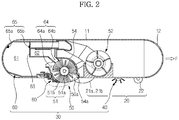
- FIG. 2 is a sectional view illustrating the autonomous cleaning device
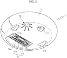
- FIG. 3 is a bottom perspective view illustrating the autonomous cleaning device.
- an autonomous cleaning device 10 may include a main body 11, a drive unit 20, a cleaning unit 30 and a controller (not shown).
- the main body 11 may be configured in various forms.
- the main body 11 may be configured in a circular form.
- the circular main body 11 has a uniform radius of rotation, and therefore, the main body 11 may avoid contact with surrounding obstacles and may easily change course. Also, during travel, the main body 11 may be prevented from being caught by surrounding obstacles.
- Various components for example such as the drive unit 20, the cleaning unit 30, various sensors 12 and 13, a display unit 14, and the controller (not show), to perform cleaning may be provided at the main body 11.
- the drive unit 20 may enable the main body 11 to travel about an area to be cleaned.
- the drive unit 20 may include left and right drive wheels 21a and 21b and a caster 22. Power from a motor (not shown) may be supplied to the left and right drive wheels 21a and 21b. Also, the left and right drive wheels 21a and 21b are mounted at the middle region of the bottom of the main body 11 and the caster 22 may be mounted at the front region of the bottom of the main body 11 so that the main body maintains a stable posture.
- left and right drive wheels 21a and 21b and the caster 22 may constitute a single assembly, which may be detachably mounted to the main body 11.
- the cleaning unit 30 may remove dust from a floor on which the main body 11 is positioned and surroundings thereof.
- the cleaning unit 30 may include a side brush 40, a brush drum unit 50 and a dust box 60.
- the side brush 40 may be rotatably mounted at one side of the edge of the bottom of the main body 11.
- the side brush 40 may deviate from the middle region of the main body with an inclination to the front F of the main body 11.
- the side brush 40 may move dust collected around the main body 11 to a floor where the main body 11 is positioned.
- the side brush 40 may extend a cleaning range to an area around a floor where the main body 11 is positioned.
- the side brush 40 may remove dust collected from a corner, which is a boundary between a floor and walls.
- the brush drum unit 50 may be mounted at a position deviating from the middle region of the bottom of the main body 11.
- the brush drum unit 50 may deviate from the left and right drive wheels 21a and 21b mounted at the middle region of the bottom of the main body 11 toward the rear R of the main body 11.
- the brush drum unit 50 may remove dust collected on a floor where the main body 11 is positioned.
- the brush drum unit 50 may include a dust introduction channel 50a forming a dust introduction route.
- the brush drum unit 50 may include a brush unit 51 provided in the dust introduction channel 50a to sweep dust off of the floor.
- the brush unit 51 may include a roller 51a and a brush 51b formed at the outer circumference of the roller 51a. Power from a motor 56 (see FIG. 4 ) may be supplied to the roller 51a. Through rotation of the roller 51a, the brush 51b may sweep up dust collected on the floor.
- the roller 51a may be formed of a rigid body, to which, however, the roller 51a is not limited.
- the brush 51b may be formed of various materials exhibiting high elasticity.
- the brush unit 51 may be driven at uniform speed to maintain uniform cleaning performance.
- the rotational speed of the crush unit 51 may be lower than the rotational speed of the brush unit 51 when a smooth floor surface is cleaned. At this time, additional current may be supplied to ensure that the brush unit 51 maintain a uniform rotational speed.
- the dust box 60 may be mounted at the rear R of the main body 11.
- An introduction port 64 of the dust box 60 may communicate with the dust introduction channel 50a of the brush drum unit 50. Consequently, dust swept by the brush unit 51 may be stored in the dust box 60 via the dust introduction channel 50a.
- the dust box 60 may be divided into a large dust box 61 and a small dust box 62 by a partition 63.
- the introduction port 64 may be divided into a first introduction port 64a provided at an inlet of the large dust box 61 and a second introduction port 64b provided at an inlet of the small dust box 62.
- the brush unit 51 may sweep relatively large dust particles into the large dust box 61.
- a blowing unit 52 may suction relatively small airborne dust, such as hair, into the small dust box 62.
- a brush cleaning member 59 may be provided at a position adjacent to the second introduction port 64b to separate hair from the brush unit 51. The hair separated from the brush unit 51 by the brush cleaning member 59 may be stored in the small dust box 62 by suction force of the blowing unit 52.
- a dust amount detection unit 65 may be provided in the dust box 60 to detect whether the dust box 60 is filled with dust.
- the dust amount detection unit 65 may include a light emitting part 65a to emit a beam and a light receiving part 65b to receive the beam. When an amount of light received by the light receiving part 65b is equal to or less than a predetermined value, it may be determined that the dust box 60 is filled with dust.
- the brush drum unit 50, the brush unit 51 and the dust box 60 may constitute a single assembly, which may be detachably mounted to the main body 11.
- the sensors 12 and 13 may include a proximity sensor 12 and/or an optical sensor 13.
- the autonomous cleaning device 10 when the autonomous cleaning device 10 travels in an arbitrary direction without a predetermined route, i.e. in a cleaning system not employing a map, the autonomous cleaning device 10 may travels about an area to be cleaned using the proximity sensor 12.
- the optical sensor 13 when the autonomous cleaning device 10 travels along a predetermined route, i.e. in a cleaning system having a map, the optical sensor 13 may be provided to receive position information of the autonomous cleaning device 10 and create a map.
- the optical sensor 13 corresponds to an embodiment of a location system. Other various methods may be provided.
- the display unit 14 may display various states of the autonomous cleaning device 10. For example, the display unit 14 may display a battery charge state, whether the dust box 60 is filled with dust, and a cleaning mode or a resting mode of the autonomous cleaning device 10.
- the controller may control the drive unit 20 and the cleaning unit 30 to efficiently perform a cleaning task.
- the controller may receive signals from the sensors 12 and 13 to avoid an obstacle or change travel modes. Also, the controller may receive a signal from the dust amount detection unit 65.
- the controller may dock with a maintenance station (not shown) to automatically remove dust from the dust box 60 or may sound an alarm to notify a user.
- the controller may receive a signal from a dust introduction detection unit 70 to distinguish between an area from which dust is introduced and an area from which dust is not introduced. For example, an area may be traveled over repeatedly, a travel speed may be reduced or rotational force of the brush unit 51 or the suction force of the blowing unit 52 may be increased to improve cleaning efficiency at an area from which dust is introduced. On the other hand, a cleaning sequence may be delayed or the number of times of travel may be reduced at an area from which dust is not introduced.
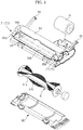
- FIG. 4 is an exploded perspective view illustrating a brush drum unit
- FIG. 5 is an exploded bottom perspective view illustrating a cover unit
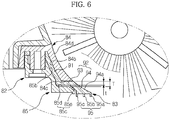
- FIG. 6 is an enlarged sectional view illustrating a blade assembly of the cover unit.
- the brush drum unit 50 may include a housing 54, a motor 56, a brush unit 51, a dust introduction detection unit 70 and a cover unit 80.
- the housing 54 may be formed generally in a semi-cylindrical shape.
- the housing 54 may be provided at the bottom thereof with a first opening 54a opened to a floor surface.
- a second opening 54b communicating with the dust box 60 may be formed at the upper side of the first opening 54a.
- the dust introduction channel 50a may be a route which extended from the first opening 54a to the second opening 54b.
- the housing 54 may be detachably mounted to the main body 11.
- a pivot arm 55 may tilt the housing 54 with respect to the main body 11.
- the housing 54 may move downward due to gravity when the autonomous cleaning device 10 travels on a smooth floor surface, for example, such as a wooden floor, exhibiting low frictional contact force with the brush unit 51, and the housing 54 may tilt upward when the autonomous cleaning device 10 travels on a floor surface, for example, such as a carpet, exhibiting high frictional contact force with the brush unit 51.
- the brush unit 51 may be tilted upward, thereby reducing load applied to the motor 56.
- the motor 56 may be mounted at the housing 54.
- the motor 56 may supply power to the brush unit 51.
- the motor 56 and the brush unit 51 may be connected to each other via a series of gears (not shown).
- the brush unit 51 may be rotatably mounted to the housing 54.
- the brush unit 51 may be rotated by power supplied from the motor 56.
- the dust introduction detection unit 70 may determine whether or not dust is introduced into the dust introduction channel 50a of the housing 54 or an introduction amount of dust.
- the controller may determine whether or not the autonomous cleaning device 10 is properly performing cleaning and which area is to be further cleaned through the operation of the dust introduction detection unit 70.
- the dust introduction detection unit 70 may include a light emitting part 71 and a light receiving part 72.
- the light emitting part 71 and the light receiving part 72 may be mounted at positions at opposite adjacent sides of the second opening 54b of the housing 54.
- the light emitting part 71 and the light receiving part 72 may be mounted at positions at opposite adjacent sides of the introduction port 64 of the dust box 60 connected to the second opening 54b of the housing 54.
- the cover unit 80 may be detachably mounted at the first opening 54a of the housing 54. A user may open the cover unit 80 to mount/separate the brush unit 51 to/from the housing 54.
- the cover unit 80 may include a cover 81 and a blade assembly 82.
- the cover 81 may have a size corresponding to the first opening 54a of the housing 54.
- the cover 81 may be formed in a hollow shape, i.e. a shape having an outer edge and a hollow interior.
- the cover 81 may be formed in a lattice shape. In this case, the lattice of the cover 81 may have a size appropriate to smoothly introduce dust.
- the blade assembly 82 may be formed at one side of the cover 81.
- the blade assembly 82 is mounted at the rear of the brush unit 51 to serve as a kind of dustpan when the brush unit 51 sweeps dust.
- the blade assembly 82 may include a blade 83, a fixing member 84 and a support member 85.
- the fixing member 84 and the support member 85 may be mounted so that the blade 83 exhibits proper rigidity and flexibility. As a result, a function of the blade 83 is improved to increase cleaning efficiency.
- the fixing member 84 may be integrally formed at one side of the cover 81.
- the blade 83 may be stacked below the fixing member 84, and the support member 85 may be stacked below the blade 83.
- the fixing member 84 is provided with a protrusion 84a having a screw groove.
- the blade 83 and the support member 85 have holes 83a and 85a through which the protrusion 84a of the fixing member 84 is inserted.
- the protrusion 84a of the fixing member 84 is sequentially inserted through the hole 83a of the blade 83 and the hole 85a of the support member 85, and then a screw S is coupled to the protrusion 84a of the fixing member 84, thereby completing the blade assembly 82.
- the blade 83 may be formed of a flexible material, for example, such as rubber, and may be mounted so as to be inclined downward toward a floor. At this time, the end of the blade 83 may come into tight contact with the floor.
- the blade 83 may include a first part 91 and a second part 92 extended from the first part 91 toward the floor.
- the first part 91 of the blade 83 is inclined downward.
- the first part 91 of the blade 83 is tightly fixed by a first fixing part 84b of the fixing member 84 and a first support part 85b of the support member 85. That is, the first part 91 of the blade 83 is inserted and supported between the first fixing part 84b of the fixing member 84 and the first support part 85b of the support member 85, and therefore, the first part 91 of the blade 83 is prevented from moving.
- the second part 92 of the blade 83 may include a moving portion 93 and a tight contact portion 94.
- the moving portion 93 may be disposed horizontally, and the tight contact portion 94 may be inclined downward.
- the moving portion 93 may have a predetermined inclination.
- a second fixing part 84c of the fixing member 84 is provided adjacent to the upper side of the second part 92 of the blade 83. That is, the second fixing part 84c of the fixing member 84 is provided adjacent to the upper side of the moving portion 93 of the second part 92 of the blade 83.
- the second fixing part 84c of the fixing member 84 pushes the moving portion 93 of the blade 83 downward so that the end of the tight contact portion 94 comes into tight contact with the floor. Also, upward movement of the moving portion 93 of the blade 83 is restricted, thereby preventing the end of the tight contact portion 94 from moving off of the floor.
- a second support part 85c of the support member 85 is provided adjacent to the lower side of the second part 92 of the blade 83. That is, the second support part 85c of the support member 85 may include a first movement restriction portion 85d and a second movement restriction portion 85e corresponding to the moving portion 93 and the tight contact portion 94 of the second part 92 of the blade 83.
- the first movement restriction portion 85d of the support member 85 is provided adjacent to the moving portion 93 of the blade 83, and the second movement restriction portion 85e of the support member 85 is also provided adjacent to the tight contact portion 94 of the blade 83.
- the moving portion 93 of the blade 83 is provided between the second fixing part 84c of the fixing member 84 and the second support part 85c of the support member 85.
- the thickness t of the moving portion 93 of the blade 83 is less than the distance T between the second fixing part 84c and the second support part 85c.
- the second support part 85c of the support member 85 may be spaced apart from at least a portion of the moving portion 93 of the blade 83 by a predetermined distance.
- the second support part 85c is spaced apart from a boundary between the moving portion 93 and the tight contact portion 94, i.e. the end of the moving portion 93, by a predetermined distance T-t.
- the second part 92 of the blade 83 may move between the second fixing part 84c of the fixing member 84 and the second support part 85c of the support member 85 within a predetermined range.
- the second support part 85c of the support member 85 prevents the second part 92 of the blade 83 from being bent in the direction opposite to the travel direction of the main body 11, thereby securing operational reliability of the blade 83.
- a plurality of contact portions 95 may be formed at the end of the second part 92 of the blade 83.
- the contact portions 95 may be spaced apart from each other and may in contact with the floor. Consequently, the end of the blade 83 comes into surface contact with the floor through the contact portions 95.
- each of the contact portions 95 may be formed in a quadrangular shape in section.
- a first contact portion 95a (see FIG. 7 ) may be formed in a wedge shape to increase contact area between the first contact portion and the floor.
- guides 84d and 94a of the blade assembly 82 may be formed to coincide with the rotational arc of the brush unit 51. That is, the first guides 84d of the fixing member 84 and the second guides 94a of the blade 83 may be smoothly connected to each other, and the first guides 84d and the second guides 94a may coincide with the rotational arc of the brush unit 51. As a result, the guides 84d and 94a of the blade assembly 82 may enable the brush unit 51 to easily suction dust.
- the guides 84d and 94a of the blade assembly 82 may not coincide with the rotational arc of the brush unit 51 but may be formed in various shapes, for example, such as a straight line or a curved line.
- FIG. 7 is a view illustrating the operation of the blade assembly when the autonomous cleaning device according to the embodiment travels on a smooth floor
- FIG. 8 is a view illustrating the operation of the blade assembly when the autonomous cleaning device travels on a floor, for example, such as a carpet, exhibiting high frictional contact force
- FIG. 9 is a view illustrating the operation of the blade assembly when the autonomous cleaning device according to the embodiment travels on a floor having a crevice.
- the autonomous cleaning device 10 may travel on a smooth floor.
- frictional force between the blade assembly 82 and the floor may be relatively small.
- the second part 92 of the blade 83 is lowered due to gravity.
- the moving portion 93 of the second part 92 is pushed downward by the second fixing part 84c of the fixing member 84. Consequently, the autonomous cleaning device 10 may travel in a state in which the contact portions 95 of the blade 83 are in tight contact with the floor.
- the end of the blade 83 is prevented from moving off of the floor, and therefore, the brush unit 51 may more efficiently sweep dust into the dust box 60.
- the moving portion 93 of the second part 92 of the blade 83 may move between the second fixing part 84c of the fixing member 84 and the second support part 85c of the support member 85 within a predetermined range, and therefore, the second part 92 of the blade 83 may exhibit a certain degree of flexibility.
- no member is mounted at the upper side of the tight contact portion 94 of the second part 92 of the blade 83.
- the tight contact portion 94 of the second part 92 of the blade 83 may exhibit flexibility due to the flexible material property thereof.
- the autonomous cleaning device 10 may travel on a coarse floor, for example such as a carpet.
- frictional force between the blade assembly 82 and the floor may be relatively large.
- force is applied to the second part 92 of the blade in the direction opposite to the direction of travel.
- the second support part 85c of the support member 85 may prevent the second part 92 of the blade 83 from being bent in the direction opposite to the direction of travel. Consequently, the shape of the blade 83 is maintained and the function of the blade 83 is also maintained.
- the support member 85 restricts the movement of the blade 83 to within a predetermined range, and therefore, the blade 83 may perform cleaning in a state in which the rigidity of the blade 83 is maintained to some extent.
- the autonomous cleaning device 10 may travel over a floor having a crevice.
- the horizontal state of the contact portions 95 formed at the end of the blade 83 may be maintained when the blade 83 passes over the crevice formed in the floor.
- a first contact portion 95a disposed at the front end passes over the crevice
- a second contact portion 95b and a third contact portion 95c disposed at the rear end come into tight contact with the floor with the result that the first contact portion 95a does not fall into the crevice.
- the second contact portion 95b and the third contact portion 95c are supported by the floor, the horizontal state of the first contact portion 95a, the second contact portion 95b and the third contact portion 95c is maintained, and therefore, the first contact portion 95a does not fall into the crevice.
- the same conditions may be applied when the second contact portion 95b or the third contact portion 95c passes over the crevice. Consequently, any one of the contact portions 95 does not fall into the crevice, and therefore, abnormal noise or abnormal operation, which may be caused when the end of the blade 83 falls into the crevice or is caught by the crevice during travel, may be prevented.
- the cleaning function and the travelling function of the autonomous cleaning device 10 may be secured based on this structure.
- FIG. 10A is a bottom exploded view illustrating a cover unit according to an embodiment
- FIG. 10B is a photograph illustrating the cover unit according to the embodiment.
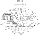
- FIGS. 11 and 12 are views illustrating the operation of a blade assembly when the autonomous cleaning device according to the embodiment travels on a tatami (straw-mat) floor.
- a blade assembly 282 may include a blade 283, a fixing member 284 and a support member 285.
- the fixing member 284 and the support member 285 may be mounted so that the blade 283 exhibits proper rigidity and flexibility.
- the blade assembly 282 will be described based on differences between the blade assembly 282 and the previously described blade assembly 82.
- the blade 283 may includes a first part 291 constituting the upper part thereof and a second part 292 extended from the first part 291 toward a floor side.
- the first part 291 is tightly fixed by a first fixing part 284b and a first support part 285b.
- the second part 292 may include a moving portion 293 and a tight contact portion 294.
- the second part 292 is moved between a second fixing part 284c and a second support part 285c. However, the movement of the second part 292 is restricted within a predetermined range, as previously described.
- the second part 292 of the blade 283 is provided at the front thereof in a direction of travel with a first contact portion 295a protruding downward.
- the first contact portion 295a may be formed in a quadrangular shape in section.
- a first contact portion 295a' may be formed in a wedge shape in section to increase contact area with the first contact portion 295a' and a floor.
- guides 284d and 294a of the blade assembly 82 are formed to coincide with the rotational arc of the brush unit 51 and the top of the first contact portion 295a' is formed to coincide with the rotational arc of the brush unit 51.
- the second part 292 is provided at the rear end of the first contact portion 295a thereof in a direction of travel with a horizontality maintaining portion 296.
- the first contact portion 295a guides dust swept up by the brush unit 51 to the dust box 60 in a state in which the first contact portion 295a is in contact with a floor.
- a rugged tatami floor 500 is cleaned as shown in the drawings, however, the first contact portion 295a falls into valleys 502 of the floor 500 and collides with ridges 501 of the floor 500 during traveling of the autonomous cleaning device 10.
- the first contact portion 295a may be damaged, the tatami floor 500 may be damaged, and noise may be generated.
- the horizontality maintaining portion 296 is provided to prevent such damage and noise.
- the horizontality maintaining portion 296 is formed to be wider than the width between neighboring ridges 501 of the tatami floor 500. Consequently, the horizontality maintaining portion 296 supports the first contact portion 295a so that the first contact portion 295a moves horizontally without falling into the valleys 502 of the tatami floor 500. For this reason, the horizontality maintaining portion 296 is formed at the end of the second part 292 with a width greater than the width between neighboring ridges 501 of the tatami floor 500. In the drawings, however, the horizontality maintaining portion 296 is shown as entirely covering the end of the second part 292 from the rear end of the first contact portion 295a.
- the first contact portion 295a contacts the floor. Consequently, the distance from the bottom of the first contact portion 295a to the floor is equal to or less than the distance from the bottom of the horizontality maintaining portion 296 to the floor. In the drawings, the distance from the bottom of the first contact portion 295a to the floor is shown as being equal to or less than the distance from the bottom of the horizontality maintaining portion 296 to the floor.
- the horizontality maintaining portion 296 may be formed of a flexible material, such as a brush, rubber, sponge or fiber, to minimize damage to the tatami floor 500. Consequently, the first contact portion 295a as well as the second part 292 comes into tight contact with the floor by the horizontality maintaining portion 296.
- a photograph of a product in which the horizontality maintaining portion 296 is formed of a brush is shown in FIG. 10B . In the photograph, the brush is attached to the end of the blade.
- the horizontality maintaining portion 296 may be formed of a material exhibiting frictional force lower than that of the first contact portion 295a since the horizontality maintaining portion 296 is provided to minimize damage to the tatami floor 500.
- the horizontality maintaining portion 296 may serve as an auxiliary brush to collect residual dust which has not been swept up by the brush unit 51 so that the residual dust is easily swept up by the brush unit 51.
- the horizontality maintaining portion 296 may not tightly contact the first contact portion 295a; however, the distance between the horizontality maintaining portion 296 and the first contact portion 295a is formed to be narrower than the width of each ridge 501 of the tatami floor 500. If the distance between the horizontality maintaining portion 296 and the first contact portion 295a is greater than the width of each ridge 501 of the tatami floor 500, the ridge 501 is inserted between the horizontality maintaining portion 296 and the first contact portion 295a with the result that noise may be generated, and the tatami floor 500 may be damaged.
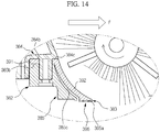
- FIGS. 13 and 14 are sectional views illustrating a blade assembly.
- a blade assembly 382 may include a blade 383, a fixing member 384 and a support member 385.
- the fixing member 384 and the support member 385 may be mounted so that the blade 383 exhibits proper rigidity and flexibility.
- the blade assembly 382 will be described based on differences between the blade assembly 382 and the previously described blade assembly 82.
- a first part 391 of the blade 383 is mounted in the horizontal direction and is tightly fixed by a first fixing part 384b of the fixing member 384 and a first support part 385b of the support member 385. That is, the first part 391 is inserted between the first fixing part 384b and the first support part 385b so that the first part 391 is pushed upward and downward, and therefore, the first part 391 is prevented from moving.
- a second part 392 of the blade 383 is inclined.
- a second fixing part 384c of the fixing member 384 is provided adjacent to the upper end of the second part 392 of the blade 383. The second fixing part 384c pushes the second part 392 of the blade 383 downward so that the lower end of the second part 392 comes into tight contact with a floor. Also, upward movement of the second part 392 of the blade 383 is restricted, thereby preventing the lower end of the second part 392 from moving off of the floor.
- a second support part 385c of the support member 385 is provided adjacent to the lower side of the second part 392 of the blade 383.
- the second support part 385c is almost in contact with the upper part of the second part 392 of the blade 383 and is spaced apart from the lower part of the second part 392 of the blade 383 by a predetermined distance. That is, the distance between the second part 392 of the blade 383 and the second support part 385c increases from the upper side to the lower side of the part 392 of the blade 383 so that the second part 392 of the blade 383 exhibits proper flexibility and rigidity.
- the second part 392 of the blade 383 may be moved by the second fixing part 384c and the second support part 385c within a predetermined range.
- the second support part 385c prevents the second part 392 of the blade 383 from being bent in the direction opposite to the travel direction of the main body 11, thereby securing operational reliability of the blade 383.
- a plurality of contact portions 395 may be formed at the lower end of the second part 392 of the blade 383.
- a front one of the contact portions 395 i.e. a first contact portion 395a, may be formed in a quadrangular or wedge shape in section.
- the second part 392 of the blade 383 is provided at the front thereof in the travel direction of the autonomous cleaning device 10 with a first contact portion 395a protruding downward.
- the first contact portion 395a may be formed in a quadrangular or wedge shape in section.
- the second part 392 is provided at the rear end of the first contact portion 395a thereof in a direction of travel with a horizontality maintaining portion 396.
- the horizontality maintaining portion 396 supports the first contact portion 395a so that the first contact portion 395a moves horizontally without falling into valleys 502 of the tatami floor 500. Consequently, noise is reduced, and damage to the tatami floor 500 is prevented.
- the horizontality maintaining portion 396 is formed to be wider than the width between neighboring ridges 501 of the tatami floor 500 so that the first contact portion 395a moves horizontally over the rugged tatami floor 500.
- the horizontality maintaining portion 396 is shown as entirely covering the lower end of the second part 392.
- the first contact portion 395a contacts the floor. Consequently, the distance from the bottom of the first contact portion 2395a to the floor is equal to or less than the distance from the bottom of the horizontality maintaining portion 396 to the floor.
- the horizontality maintaining portion 396 may be formed of a flexible material, such as a brush, rubber, sponge or fiber, to minimize damage to the tatami floor 500.
- FIGS. 13 and 14 The operation of the blade assembly 382 shown in FIGS. 13 and 14 may be easily understood with reference to FIGS. 7 to 12 , and therefore, a description thereof will not be given.
- the blade of the autonomous cleaning device is prevented from becoming misaligned due to assembly tolerance or injection tolerance, and the blade is prevented from moving off of a floor, thereby improving cleaning performance.
- the blade is prevented from being bent, thereby securing travel and cleaning performance of the autonomous cleaning device.
- the shape of the blade assembly is approximated to the rotational arc of the brush, thereby improving cleaning performance of the autonomous cleaning device.
Claims (8)
- Dispositif de nettoyage autonome (10) comprenant:un corps principal (11) ayant une ouverture;une unité de brosse (51) prévue en rotation dans l'ouverture du corps principal (11); etun ensemble lame (282, 382) pour guider l'introduction de la poussière balayée par l'unité de brosse dans laquelle l'ensemble lame comprend:une lame (283, 383) s'étendant vers un plancher, la lame comportant une partie contact (295a, 295a', 395a, 395a') pour établir un contact avec le sol,caractérisé en ce que l'assemblage de lame comprend en outreune partie maintien (296, 396) située derrière la partie contact (295a, 295a', 395a, 395a') dans le sens du déplacement pour entrer en contact avec le sol, la partie maintien formée d'un matériau différent de celui de la partie contact, dans lequel la partie maintien (296, 396) est fixée à une surface inférieure de la lame.
- Dispositif de nettoyage autonome selon la revendication 1, dans lequel la partie maintien (296, 396) est disposée dans une direction longitudinale de la lame.
- Dispositif de nettoyage autonome selon la revendication 2, dans lequel une largeur de la partie maintien est sélectionnée de telle sorte que la partie contact puisse se déplacer à travers un sol en tatami sans que la partie contact ne tombe dans les vallées du sol en tatami.
- Dispositif de nettoyage autonome selon la revendication 3, dans lequel la lame (283, 383) est conçue pour se plier vers le bas lorsque la partie contact établit un contact par friction avec le sol.
- Dispositif de nettoyage autonome selon la revendication 1, dans lequel la partie maintien (296, 396) est constituée du matériau présentant une force de friction inférieure à celle de la partie contact.
- Dispositif de nettoyage autonome selon la revendication 5, dans lequel la lame (283, 383) est constituée d'un matériau en caoutchouc et la partie maintien (296, 396) est constituée d'un matériau fibreux.
- Dispositif de nettoyage autonome selon la revendication 5, dans lequel la lame (283, 383) est constituée d'un matériau en caoutchouc et la partie maintien (296, 396) est constituée d'un matériau spongieux.
- Dispositif de nettoyage autonome selon la revendication 1, dans lequel la partie maintien (296, 396) sert à recueillir la poussière résiduelle qui n'a pas été balayée par l'unité de brosse.
Applications Claiming Priority (3)
| Application Number | Priority Date | Filing Date | Title |
|---|---|---|---|
| KR20100103778 | 2010-10-25 | ||
| KR1020110086080A KR101573742B1 (ko) | 2010-10-25 | 2011-08-26 | 로봇청소기 |
| EP11186505.1A EP2443978B1 (fr) | 2010-10-25 | 2011-10-25 | Dispositif de nettoyage autonome |
Related Parent Applications (3)
| Application Number | Title | Priority Date | Filing Date |
|---|---|---|---|
| EP11186505.1A Division-Into EP2443978B1 (fr) | 2010-10-25 | 2011-10-25 | Dispositif de nettoyage autonome |
| EP11186505.1A Division EP2443978B1 (fr) | 2010-10-25 | 2011-10-25 | Dispositif de nettoyage autonome |
| EP11186505.1 Division | 2011-10-25 |
Publications (3)
| Publication Number | Publication Date |
|---|---|
| EP2529654A2 EP2529654A2 (fr) | 2012-12-05 |
| EP2529654A3 EP2529654A3 (fr) | 2013-10-16 |
| EP2529654B1 true EP2529654B1 (fr) | 2018-10-24 |
Family
ID=44992568
Family Applications (2)
| Application Number | Title | Priority Date | Filing Date |
|---|---|---|---|
| EP12182367.8A Active EP2529654B1 (fr) | 2010-10-25 | 2011-10-25 | Dispositif de nettoyage autonome |
| EP11186505.1A Active EP2443978B1 (fr) | 2010-10-25 | 2011-10-25 | Dispositif de nettoyage autonome |
Family Applications After (1)
| Application Number | Title | Priority Date | Filing Date |
|---|---|---|---|
| EP11186505.1A Active EP2443978B1 (fr) | 2010-10-25 | 2011-10-25 | Dispositif de nettoyage autonome |
Country Status (5)
| Country | Link |
|---|---|
| US (2) | US9220385B2 (fr) |
| EP (2) | EP2529654B1 (fr) |
| JP (2) | JP2012090984A (fr) |
| KR (1) | KR101573742B1 (fr) |
| CN (2) | CN102525351B (fr) |
Families Citing this family (81)
| Publication number | Priority date | Publication date | Assignee | Title |
|---|---|---|---|---|
| CN201840427U (zh) * | 2010-10-11 | 2011-05-25 | 洋通工业股份有限公司 | 驱动模块 |
| KR101970584B1 (ko) | 2011-09-01 | 2019-08-27 | 삼성전자주식회사 | 청소 시스템과 그 메인터넌스 스테이션 |
| EP2570064B1 (fr) | 2011-09-01 | 2015-04-01 | Samsung Electronics Co., Ltd. | Ensemble de roues motrices et robot nettoyeur l'utilisant |
| EP2570067A1 (fr) * | 2011-09-01 | 2013-03-20 | Samsung Electronics Co., Ltd. | Appareil de nettoyage autonome et son procédé de commande |
| CN103479295A (zh) * | 2012-06-12 | 2014-01-01 | 乐金电子(天津)电器有限公司 | 手提式吸尘器 |
| EP2689701B1 (fr) * | 2012-07-25 | 2018-12-19 | Samsung Electronics Co., Ltd. | Dispositif de nettoyage autonome |
| KR20140015099A (ko) * | 2012-07-25 | 2014-02-06 | 삼성전자주식회사 | 로봇청소기 |
| US9939529B2 (en) | 2012-08-27 | 2018-04-10 | Aktiebolaget Electrolux | Robot positioning system |
| KR101393229B1 (ko) * | 2012-09-13 | 2014-05-12 | 순천대학교 산학협력단 | 진공청소기 흡입유닛 |
| AU349618S (en) | 2012-09-24 | 2013-07-04 | Dyson Technology Ltd | A vacuum cleaner |
| KR102015315B1 (ko) * | 2012-10-09 | 2019-10-21 | 삼성전자주식회사 | 청소 로봇 및 그 제어 방법 |
| EP2934268B8 (fr) * | 2012-12-18 | 2019-03-27 | Alfred Kärcher SE & Co. KG | Brosse de nettoyage pour un appareil de nettoyage de sol et appareil de nettoyage de sol avec une brosse de nettoyage |
| EP2902120B1 (fr) * | 2012-12-25 | 2020-07-15 | Miraikikai, Inc. | Robot de nettoyage à déplacement autonome |
| WO2014169943A1 (fr) | 2013-04-15 | 2014-10-23 | Aktiebolaget Electrolux | Dispositif de nettoyage sous vide robotisé |
| KR20150141979A (ko) | 2013-04-15 | 2015-12-21 | 악티에볼라겟 엘렉트로룩스 | 돌출 측부 브러시를 구비하는 로봇 진공 청소기 |
| TW201446202A (zh) * | 2013-06-05 | 2014-12-16 | Uni Ring Tech Co Ltd | 自走式清潔裝置之掃刷底蓋構造及其組裝、刮掃方法 |
| JP6144971B2 (ja) * | 2013-06-11 | 2017-06-07 | シャープ株式会社 | 掃除機 |
| JP6204080B2 (ja) * | 2013-06-17 | 2017-09-27 | 東芝ライフスタイル株式会社 | 電気掃除機 |
| CN104248397B (zh) * | 2013-06-28 | 2017-06-20 | 科沃斯机器人股份有限公司 | 清洁装置、滚刷清洁舱及清洁系统 |
| CN105744872B (zh) | 2013-12-19 | 2020-01-14 | 伊莱克斯公司 | 旋转侧刷的自适应速度控制 |
| JP6494118B2 (ja) | 2013-12-19 | 2019-04-03 | アクチエボラゲット エレクトロルックス | 障害物の乗り上げの検出に伴うロボット掃除機の制御方法、並びに、当該方法を有するロボット掃除機、プログラム、及びコンピュータ製品 |
| EP3084538B1 (fr) | 2013-12-19 | 2017-11-01 | Aktiebolaget Electrolux | Dispositif de nettoyage robotisé à fonction d'enregistrement de périmètre |
| WO2015090399A1 (fr) | 2013-12-19 | 2015-06-25 | Aktiebolaget Electrolux | Dispositif de nettoyage robotisé et procédé de reconnaissance de point de repère |
| KR102116596B1 (ko) | 2013-12-19 | 2020-05-28 | 에이비 엘렉트로룩스 | 나선형 패턴으로 이동하는 사이드 브러시를 구비한 로봇 진공 청소기 |
| EP3084539B1 (fr) | 2013-12-19 | 2019-02-20 | Aktiebolaget Electrolux | Priorisation de zones de nettoyage |
| EP3084540B1 (fr) | 2013-12-19 | 2021-04-14 | Aktiebolaget Electrolux | Robot de nettoyage et methode d'exploitation associee |
| CN105848545B (zh) | 2013-12-20 | 2019-02-19 | 伊莱克斯公司 | 灰尘容器 |
| KR101556177B1 (ko) * | 2014-05-07 | 2015-09-30 | 엘지전자 주식회사 | 진공 청소기 |
| KR101573192B1 (ko) * | 2014-05-30 | 2015-12-01 | 주식회사 유진로봇 | 주행 및 청소 능력이 향상된 청소 로봇 |
| WO2016005012A1 (fr) | 2014-07-10 | 2016-01-14 | Aktiebolaget Electrolux | Procédé de détection d'une erreur de mesure dans un dispositif de nettoyage robotisé |
| DE102014111702A1 (de) * | 2014-08-15 | 2016-02-18 | Vorwerk & Co. Interholding Gmbh | Elektroteppichbürste zum Reinigen eines Untergrunds |
| KR20160025392A (ko) * | 2014-08-27 | 2016-03-08 | 에브리봇 주식회사 | 흡입 노즐, 로봇 청소기 및 그의 제어 방법 |
| AU360807S (en) | 2014-08-28 | 2015-03-26 | Dyson Technology Ltd | Vacuum cleaner |
| AU360831S (en) | 2014-08-28 | 2015-03-30 | Dyson Technology Ltd | Vacuum cleaner |
| AU360824S (en) | 2014-08-28 | 2015-03-30 | Dyson Technology Ltd | Vacuum cleaner |
| AU360827S (en) | 2014-08-28 | 2015-03-30 | Dyson Technology Ltd | Vacuum cleaner |
| AU360829S (en) | 2014-08-28 | 2015-03-30 | Dyson Technology Ltd | Vacuum cleaner |
| AU360979S (en) | 2014-08-28 | 2015-04-08 | Dyson Technology Ltd | Vacuum cleaner |
| AU360825S (en) | 2014-08-28 | 2015-03-30 | Dyson Technology Ltd | Vacuum cleaner |
| KR102271782B1 (ko) | 2014-09-08 | 2021-06-30 | 에이비 엘렉트로룩스 | 로봇 진공 청소기 |
| EP3190939B1 (fr) | 2014-09-08 | 2021-07-21 | Aktiebolaget Electrolux | Aspirateur robot autonomous |
| CN106998980B (zh) | 2014-12-10 | 2021-12-17 | 伊莱克斯公司 | 使用激光传感器检测地板类型 |
| WO2016091320A1 (fr) | 2014-12-12 | 2016-06-16 | Aktiebolaget Electrolux | Brosse latérale et dispositif de nettoyage robotisé |
| KR102339531B1 (ko) | 2014-12-16 | 2021-12-16 | 에이비 엘렉트로룩스 | 로봇 청소 장치를 위한 경험-기반의 로드맵 |
| US10678251B2 (en) | 2014-12-16 | 2020-06-09 | Aktiebolaget Electrolux | Cleaning method for a robotic cleaning device |
| JP6552033B2 (ja) * | 2015-01-16 | 2019-07-31 | 株式会社コーワ | 掃除機用吸込口及び電気掃除機 |
| JP5888446B1 (ja) * | 2015-02-12 | 2016-03-22 | 富士電機株式会社 | 床面汚染測定システム |
| EP3282912B1 (fr) | 2015-04-17 | 2020-06-10 | Aktiebolaget Electrolux | Dispositif robotique de nettoyage et un procédé de contrôle pour le dispositif robotique de nettoyage |
| EP3344104B1 (fr) | 2015-09-03 | 2020-12-30 | Aktiebolaget Electrolux | Système de dispositifs de nettoyage robotisés |
| CN105182974B (zh) * | 2015-09-16 | 2018-07-31 | 江苏拓新天机器人科技有限公司 | 一种扫地机器人的智能寻路方法 |
| CN108135421B (zh) | 2015-10-10 | 2021-01-29 | 深圳市赫兹科技有限公司 | 地面清洁器及其水槽结构 |
| KR102072512B1 (ko) | 2015-10-10 | 2020-02-03 | 하이제로 테크놀로지스 캄파니 리미티드 | 바닥 청소기 |
| JP6708820B2 (ja) * | 2015-10-10 | 2020-06-10 | 深▲セン▼市赫▲ジ▼科技有限公司HIZERO Technologies Co.,Ltd. | 床面掃除機及びその掃除コラム清掃機構 |
| WO2017059601A1 (fr) | 2015-10-10 | 2017-04-13 | 深圳市赫兹科技有限公司 | Dispositif de nettoyage de sol, élément de rouleau de nettoyage, et rouleau en éponge |
| NL2015967B1 (nl) * | 2015-12-16 | 2017-06-30 | Viku B V | Combinatie van een autonome reinigingsinrichting en een afvalbak. |
| KR102588486B1 (ko) | 2016-03-15 | 2023-10-11 | 에이비 엘렉트로룩스 | 로봇 청소 장치 및 로봇 청소 장치에서의 절벽 검출 실시 방법 |
| DE102016105218A1 (de) * | 2016-03-21 | 2017-09-21 | Miele & Cie. Kg | Saugroboter |
| WO2017194102A1 (fr) | 2016-05-11 | 2017-11-16 | Aktiebolaget Electrolux | Dispositif de nettoyage robotisé |
| KR102485720B1 (ko) * | 2016-05-18 | 2023-01-09 | 삼성전자주식회사 | 청소기 |
| CN107411647A (zh) * | 2016-05-23 | 2017-12-01 | 深圳市智意科技有限公司 | 浮动式单刮条组件及其洗地机 |
| CN107708514A (zh) * | 2016-05-23 | 2018-02-16 | 深圳市智意科技有限公司 | 洗地机清洁装置及洗地机 |
| KR101911295B1 (ko) | 2016-12-30 | 2018-10-24 | 엘지전자 주식회사 | 청소기 |
| CN113854896B (zh) * | 2016-12-30 | 2023-04-14 | Lg电子株式会社 | 清洁器 |
| JP6158456B2 (ja) * | 2017-03-31 | 2017-07-05 | シャープ株式会社 | 掃除機 |
| US11474533B2 (en) | 2017-06-02 | 2022-10-18 | Aktiebolaget Electrolux | Method of detecting a difference in level of a surface in front of a robotic cleaning device |
| JP7008174B2 (ja) * | 2017-08-25 | 2022-01-25 | パナソニックIpマネジメント株式会社 | 自律走行型掃除機 |
| US11921517B2 (en) | 2017-09-26 | 2024-03-05 | Aktiebolaget Electrolux | Controlling movement of a robotic cleaning device |
| WO2019157653A1 (fr) | 2018-02-13 | 2019-08-22 | 深圳市赫兹科技有限公司 | Dispositif de nettoyage mobile bidirectionnel |
| CN108664027B (zh) * | 2018-05-17 | 2020-04-14 | 深圳市无限动力发展有限公司 | 监控扫地机异常状态的方法和装置 |
| CN109200512A (zh) * | 2018-09-25 | 2019-01-15 | 上海海事大学 | 一种无人消防船 |
| CN108968798A (zh) * | 2018-09-30 | 2018-12-11 | 苏州市春菊电器有限公司 | 一种可移除式滚刷清理装置 |
| US20220047141A1 (en) * | 2018-12-21 | 2022-02-17 | Positec Power Tools (Suzhou) Co., Ltd. | Cleaning robot and control method |
| USD936719S1 (en) * | 2019-02-20 | 2021-11-23 | Lg Electronics Inc. | Home hub robot |
| UA41383S (uk) * | 2019-03-18 | 2020-04-27 | Бейцзін Сяомі Мо | Прибиральний пристрій |
| USD999352S1 (en) | 2019-05-23 | 2023-09-19 | Samsung Electronics Co., Ltd. | Air conditioner |
| US20210030232A1 (en) * | 2019-07-31 | 2021-02-04 | Lg Electronics Inc. | Cleaner |
| USD940771S1 (en) * | 2019-08-15 | 2022-01-11 | Beijing Xiaomi Mobile Software Co., Ltd. | Robot vacuum cleaner |
| JP2021126159A (ja) * | 2020-02-10 | 2021-09-02 | 株式会社マキタ | ロボット集塵機 |
| DE102020210232A1 (de) | 2020-08-12 | 2022-02-17 | BSH Hausgeräte GmbH | Bodenbearbeitungsmaschine |
| US11832780B2 (en) * | 2021-07-29 | 2023-12-05 | Irobot Corporation | Mobile cleaning robot dustpan |
| DE102022211259A1 (de) | 2022-10-24 | 2024-04-25 | BSH Hausgeräte GmbH | Bodenreiniger mit beweglich gelagertem Saugmund |
Family Cites Families (25)
| Publication number | Priority date | Publication date | Assignee | Title |
|---|---|---|---|---|
| US3460188A (en) | 1966-04-26 | 1969-08-12 | Gen Electric | Vacuum cleaner |
| US3892003A (en) | 1973-03-16 | 1975-07-01 | Tennant Co | Power floor treating apparatus |
| JPS5759088Y2 (fr) * | 1977-04-07 | 1982-12-17 | ||
| JPS53138470A (en) | 1977-05-09 | 1978-12-02 | Kanegafuchi Chem Ind Co Ltd | Polypropylene resin composition foam and its production |
| US4709436A (en) | 1986-02-06 | 1987-12-01 | Shop-Vac Corporation | Debris pan for rotary brush sweeper |
| US5054156A (en) | 1988-04-20 | 1991-10-08 | Hitachi, Ltd. | Suction nozzle with rotary brush for vacuum cleaner |
| US4864682A (en) | 1988-05-02 | 1989-09-12 | Whirlpool Corporation | Self-adjusting wiper strip assembly for a vacuum cleaner |
| US5806123A (en) | 1994-10-05 | 1998-09-15 | Tono; Gianni | Variable elasticity collection pan for floor cleaning machines |
| JPH08294468A (ja) * | 1995-04-27 | 1996-11-12 | Sanyo Electric Co Ltd | 床用吸込具 |
| JPH09206262A (ja) * | 1996-01-31 | 1997-08-12 | Amano Corp | 床面清掃機及び床面洗浄機用スキージ |
| JP3366177B2 (ja) * | 1996-01-31 | 2003-01-14 | アマノ株式会社 | 床面洗浄機用スキージ |
| CA2198404A1 (fr) | 1997-02-25 | 1998-08-25 | Carl Kidd | Grattoir a lames multiples flexibles servant a enlever les cheveux et les charpies |
| CN2373483Y (zh) * | 1998-10-06 | 2000-04-12 | 李敬德 | 人力扫地机 |
| JP3903299B2 (ja) * | 2001-06-21 | 2007-04-11 | 三菱電機株式会社 | 電気掃除機用床ブラシ |
| JP2004350826A (ja) * | 2003-05-28 | 2004-12-16 | Matsushita Electric Ind Co Ltd | 電気掃除機 |
| JP2005040447A (ja) | 2003-07-24 | 2005-02-17 | Kao Corp | 清掃具 |
| ATE394066T1 (de) | 2004-02-04 | 2008-05-15 | Johnson & Son Inc S C | Oberflächenbehandlungsvorrichtung mit reinigungssystem auf patronengrundlage |
| JP4402608B2 (ja) * | 2004-03-31 | 2010-01-20 | 花王株式会社 | 清掃具 |
| KR100544480B1 (ko) | 2004-05-12 | 2006-01-24 | 삼성광주전자 주식회사 | 로봇 청소기 |
| KR100588061B1 (ko) * | 2004-12-22 | 2006-06-09 | 주식회사유진로보틱스 | 이중흡입장치가 구비된 청소용 로봇 |
| US8117714B2 (en) | 2005-03-09 | 2012-02-21 | Bissell Homecare, Inc. | Vacuum cleaner with hair collection element |
| JP2008132299A (ja) * | 2006-11-28 | 2008-06-12 | Samsung Kwangju Electronics Co Ltd | 掃除機 |
| KR100848964B1 (ko) | 2006-12-22 | 2008-07-29 | 주식회사 유진로봇 | 로봇청소기의 흡진 어셈블리 |
| KR20090063334A (ko) * | 2007-12-14 | 2009-06-18 | 웅진코웨이주식회사 | 로봇청소기의 브러쉬 흡입장치 |
| DE102008004966A1 (de) | 2008-01-11 | 2009-07-23 | Alfred Kärcher Gmbh & Co. Kg | Saugdüse |
-
2011
- 2011-08-26 KR KR1020110086080A patent/KR101573742B1/ko active IP Right Grant
- 2011-10-24 JP JP2011233194A patent/JP2012090984A/ja active Pending
- 2011-10-24 US US13/279,892 patent/US9220385B2/en active Active
- 2011-10-25 CN CN201110343092.XA patent/CN102525351B/zh active Active
- 2011-10-25 EP EP12182367.8A patent/EP2529654B1/fr active Active
- 2011-10-25 EP EP11186505.1A patent/EP2443978B1/fr active Active
- 2011-10-25 CN CN201210344623.1A patent/CN102908107B/zh active Active
-
2012
- 2012-08-28 US US13/596,556 patent/US8732897B2/en active Active
- 2012-08-30 JP JP2012190090A patent/JP2012228619A/ja active Pending
Non-Patent Citations (1)
| Title |
|---|
| None * |
Also Published As
| Publication number | Publication date |
|---|---|
| KR101573742B1 (ko) | 2015-12-07 |
| EP2529654A2 (fr) | 2012-12-05 |
| US9220385B2 (en) | 2015-12-29 |
| EP2529654A3 (fr) | 2013-10-16 |
| EP2443978A2 (fr) | 2012-04-25 |
| JP2012228619A (ja) | 2012-11-22 |
| KR20120042642A (ko) | 2012-05-03 |
| CN102525351B (zh) | 2016-02-17 |
| CN102908107B (zh) | 2016-06-29 |
| US20120096656A1 (en) | 2012-04-26 |
| CN102525351A (zh) | 2012-07-04 |
| EP2443978B1 (fr) | 2017-01-18 |
| US20120317745A1 (en) | 2012-12-20 |
| JP2012090984A (ja) | 2012-05-17 |
| EP2443978A3 (fr) | 2013-10-16 |
| CN102908107A (zh) | 2013-02-06 |
| US8732897B2 (en) | 2014-05-27 |
Similar Documents
| Publication | Publication Date | Title |
|---|---|---|
| EP2529654B1 (fr) | Dispositif de nettoyage autonome | |
| US9854954B2 (en) | Robot cleaner | |
| EP2689701B1 (fr) | Dispositif de nettoyage autonome | |
| EP2253258B1 (fr) | Machine de nettoyage autonome | |
| EP3162265B1 (fr) | Dispositif de nettoyage de type à déplacement autonome | |
| JP7117606B2 (ja) | 自律走行型掃除機 | |
| CN105982620B (zh) | 自动清洁设备的风道结构、风路结构和自动清洁设备 | |
| KR101413259B1 (ko) | 로봇청소기 | |
| JP7065275B2 (ja) | 自律走行型掃除機 | |
| CN212261269U (zh) | 清洁机器人及其边扫组件 | |
| JP7249496B2 (ja) | 自律走行型掃除機 |
Legal Events
| Date | Code | Title | Description |
|---|---|---|---|
| PUAI | Public reference made under article 153(3) epc to a published international application that has entered the european phase |
Free format text: ORIGINAL CODE: 0009012 |
|
| AC | Divisional application: reference to earlier application |
Ref document number: 2443978 Country of ref document: EP Kind code of ref document: P |
|
| AK | Designated contracting states |
Kind code of ref document: A2 Designated state(s): AL AT BE BG CH CY CZ DE DK EE ES FI FR GB GR HR HU IE IS IT LI LT LU LV MC MK MT NL NO PL PT RO RS SE SI SK SM TR |
|
| AX | Request for extension of the european patent |
Extension state: BA ME |
|
| PUAL | Search report despatched |
Free format text: ORIGINAL CODE: 0009013 |
|
| AK | Designated contracting states |
Kind code of ref document: A3 Designated state(s): AL AT BE BG CH CY CZ DE DK EE ES FI FR GB GR HR HU IE IS IT LI LT LU LV MC MK MT NL NO PL PT RO RS SE SI SK SM TR |
|
| AX | Request for extension of the european patent |
Extension state: BA ME |
|
| RIC1 | Information provided on ipc code assigned before grant |
Ipc: A47L 11/40 20060101ALI20130906BHEP Ipc: A47L 9/04 20060101AFI20130906BHEP Ipc: A47L 9/06 20060101ALI20130906BHEP |
|
| 17P | Request for examination filed |
Effective date: 20140331 |
|
| RBV | Designated contracting states (corrected) |
Designated state(s): AL AT BE BG CH CY CZ DE DK EE ES FI FR GB GR HR HU IE IS IT LI LT LU LV MC MK MT NL NO PL PT RO RS SE SI SK SM TR |
|
| 17Q | First examination report despatched |
Effective date: 20161115 |
|
| GRAP | Despatch of communication of intention to grant a patent |
Free format text: ORIGINAL CODE: EPIDOSNIGR1 |
|
| INTG | Intention to grant announced |
Effective date: 20180529 |
|
| GRAS | Grant fee paid |
Free format text: ORIGINAL CODE: EPIDOSNIGR3 |
|
| GRAA | (expected) grant |
Free format text: ORIGINAL CODE: 0009210 |
|
| AC | Divisional application: reference to earlier application |
Ref document number: 2443978 Country of ref document: EP Kind code of ref document: P |
|
| AK | Designated contracting states |
Kind code of ref document: B1 Designated state(s): AL AT BE BG CH CY CZ DE DK EE ES FI FR GB GR HR HU IE IS IT LI LT LU LV MC MK MT NL NO PL PT RO RS SE SI SK SM TR |
|
| REG | Reference to a national code |
Ref country code: GB Ref legal event code: FG4D |
|
| REG | Reference to a national code |
Ref country code: CH Ref legal event code: EP |
|
| REG | Reference to a national code |
Ref country code: IE Ref legal event code: FG4D |
|
| REG | Reference to a national code |
Ref country code: DE Ref legal event code: R096 Ref document number: 602011053325 Country of ref document: DE Ref country code: AT Ref legal event code: REF Ref document number: 1055677 Country of ref document: AT Kind code of ref document: T Effective date: 20181115 |
|
| REG | Reference to a national code |
Ref country code: NL Ref legal event code: MP Effective date: 20181024 |
|
| REG | Reference to a national code |
Ref country code: LT Ref legal event code: MG4D |
|
| REG | Reference to a national code |
Ref country code: AT Ref legal event code: MK05 Ref document number: 1055677 Country of ref document: AT Kind code of ref document: T Effective date: 20181024 |
|
| PG25 | Lapsed in a contracting state [announced via postgrant information from national office to epo] |
Ref country code: NL Free format text: LAPSE BECAUSE OF FAILURE TO SUBMIT A TRANSLATION OF THE DESCRIPTION OR TO PAY THE FEE WITHIN THE PRESCRIBED TIME-LIMIT Effective date: 20181024 |
|
| PG25 | Lapsed in a contracting state [announced via postgrant information from national office to epo] |
Ref country code: IS Free format text: LAPSE BECAUSE OF FAILURE TO SUBMIT A TRANSLATION OF THE DESCRIPTION OR TO PAY THE FEE WITHIN THE PRESCRIBED TIME-LIMIT Effective date: 20190224 Ref country code: FI Free format text: LAPSE BECAUSE OF FAILURE TO SUBMIT A TRANSLATION OF THE DESCRIPTION OR TO PAY THE FEE WITHIN THE PRESCRIBED TIME-LIMIT Effective date: 20181024 Ref country code: NO Free format text: LAPSE BECAUSE OF FAILURE TO SUBMIT A TRANSLATION OF THE DESCRIPTION OR TO PAY THE FEE WITHIN THE PRESCRIBED TIME-LIMIT Effective date: 20190124 Ref country code: LV Free format text: LAPSE BECAUSE OF FAILURE TO SUBMIT A TRANSLATION OF THE DESCRIPTION OR TO PAY THE FEE WITHIN THE PRESCRIBED TIME-LIMIT Effective date: 20181024 Ref country code: AT Free format text: LAPSE BECAUSE OF FAILURE TO SUBMIT A TRANSLATION OF THE DESCRIPTION OR TO PAY THE FEE WITHIN THE PRESCRIBED TIME-LIMIT Effective date: 20181024 Ref country code: LT Free format text: LAPSE BECAUSE OF FAILURE TO SUBMIT A TRANSLATION OF THE DESCRIPTION OR TO PAY THE FEE WITHIN THE PRESCRIBED TIME-LIMIT Effective date: 20181024 Ref country code: ES Free format text: LAPSE BECAUSE OF FAILURE TO SUBMIT A TRANSLATION OF THE DESCRIPTION OR TO PAY THE FEE WITHIN THE PRESCRIBED TIME-LIMIT Effective date: 20181024 Ref country code: BG Free format text: LAPSE BECAUSE OF FAILURE TO SUBMIT A TRANSLATION OF THE DESCRIPTION OR TO PAY THE FEE WITHIN THE PRESCRIBED TIME-LIMIT Effective date: 20190124 Ref country code: PL Free format text: LAPSE BECAUSE OF FAILURE TO SUBMIT A TRANSLATION OF THE DESCRIPTION OR TO PAY THE FEE WITHIN THE PRESCRIBED TIME-LIMIT Effective date: 20181024 Ref country code: HR Free format text: LAPSE BECAUSE OF FAILURE TO SUBMIT A TRANSLATION OF THE DESCRIPTION OR TO PAY THE FEE WITHIN THE PRESCRIBED TIME-LIMIT Effective date: 20181024 |
|
| PG25 | Lapsed in a contracting state [announced via postgrant information from national office to epo] |
Ref country code: PT Free format text: LAPSE BECAUSE OF FAILURE TO SUBMIT A TRANSLATION OF THE DESCRIPTION OR TO PAY THE FEE WITHIN THE PRESCRIBED TIME-LIMIT Effective date: 20190224 Ref country code: AL Free format text: LAPSE BECAUSE OF FAILURE TO SUBMIT A TRANSLATION OF THE DESCRIPTION OR TO PAY THE FEE WITHIN THE PRESCRIBED TIME-LIMIT Effective date: 20181024 Ref country code: SE Free format text: LAPSE BECAUSE OF FAILURE TO SUBMIT A TRANSLATION OF THE DESCRIPTION OR TO PAY THE FEE WITHIN THE PRESCRIBED TIME-LIMIT Effective date: 20181024 Ref country code: GR Free format text: LAPSE BECAUSE OF FAILURE TO SUBMIT A TRANSLATION OF THE DESCRIPTION OR TO PAY THE FEE WITHIN THE PRESCRIBED TIME-LIMIT Effective date: 20190125 Ref country code: RS Free format text: LAPSE BECAUSE OF FAILURE TO SUBMIT A TRANSLATION OF THE DESCRIPTION OR TO PAY THE FEE WITHIN THE PRESCRIBED TIME-LIMIT Effective date: 20181024 |
|
| REG | Reference to a national code |
Ref country code: CH Ref legal event code: PL |
|
| REG | Reference to a national code |
Ref country code: BE Ref legal event code: MM Effective date: 20181031 |
|
| PG25 | Lapsed in a contracting state [announced via postgrant information from national office to epo] |
Ref country code: LU Free format text: LAPSE BECAUSE OF NON-PAYMENT OF DUE FEES Effective date: 20181025 |
|
| REG | Reference to a national code |
Ref country code: IE Ref legal event code: MM4A |
|
| REG | Reference to a national code |
Ref country code: DE Ref legal event code: R097 Ref document number: 602011053325 Country of ref document: DE |
|
| PG25 | Lapsed in a contracting state [announced via postgrant information from national office to epo] |
Ref country code: IT Free format text: LAPSE BECAUSE OF FAILURE TO SUBMIT A TRANSLATION OF THE DESCRIPTION OR TO PAY THE FEE WITHIN THE PRESCRIBED TIME-LIMIT Effective date: 20181024 Ref country code: CZ Free format text: LAPSE BECAUSE OF FAILURE TO SUBMIT A TRANSLATION OF THE DESCRIPTION OR TO PAY THE FEE WITHIN THE PRESCRIBED TIME-LIMIT Effective date: 20181024 Ref country code: DK Free format text: LAPSE BECAUSE OF FAILURE TO SUBMIT A TRANSLATION OF THE DESCRIPTION OR TO PAY THE FEE WITHIN THE PRESCRIBED TIME-LIMIT Effective date: 20181024 |
|
| PG25 | Lapsed in a contracting state [announced via postgrant information from national office to epo] |
Ref country code: EE Free format text: LAPSE BECAUSE OF FAILURE TO SUBMIT A TRANSLATION OF THE DESCRIPTION OR TO PAY THE FEE WITHIN THE PRESCRIBED TIME-LIMIT Effective date: 20181024 Ref country code: SM Free format text: LAPSE BECAUSE OF FAILURE TO SUBMIT A TRANSLATION OF THE DESCRIPTION OR TO PAY THE FEE WITHIN THE PRESCRIBED TIME-LIMIT Effective date: 20181024 Ref country code: RO Free format text: LAPSE BECAUSE OF FAILURE TO SUBMIT A TRANSLATION OF THE DESCRIPTION OR TO PAY THE FEE WITHIN THE PRESCRIBED TIME-LIMIT Effective date: 20181024 Ref country code: BE Free format text: LAPSE BECAUSE OF NON-PAYMENT OF DUE FEES Effective date: 20181031 Ref country code: CH Free format text: LAPSE BECAUSE OF NON-PAYMENT OF DUE FEES Effective date: 20181031 Ref country code: LI Free format text: LAPSE BECAUSE OF NON-PAYMENT OF DUE FEES Effective date: 20181031 Ref country code: SK Free format text: LAPSE BECAUSE OF FAILURE TO SUBMIT A TRANSLATION OF THE DESCRIPTION OR TO PAY THE FEE WITHIN THE PRESCRIBED TIME-LIMIT Effective date: 20181024 Ref country code: MC Free format text: LAPSE BECAUSE OF FAILURE TO SUBMIT A TRANSLATION OF THE DESCRIPTION OR TO PAY THE FEE WITHIN THE PRESCRIBED TIME-LIMIT Effective date: 20181024 |
|
| PLBE | No opposition filed within time limit |
Free format text: ORIGINAL CODE: 0009261 |
|
| STAA | Information on the status of an ep patent application or granted ep patent |
Free format text: STATUS: NO OPPOSITION FILED WITHIN TIME LIMIT |
|
| 26N | No opposition filed |
Effective date: 20190725 |
|
| PG25 | Lapsed in a contracting state [announced via postgrant information from national office to epo] |
Ref country code: IE Free format text: LAPSE BECAUSE OF NON-PAYMENT OF DUE FEES Effective date: 20181025 Ref country code: FR Free format text: LAPSE BECAUSE OF NON-PAYMENT OF DUE FEES Effective date: 20181224 Ref country code: SI Free format text: LAPSE BECAUSE OF FAILURE TO SUBMIT A TRANSLATION OF THE DESCRIPTION OR TO PAY THE FEE WITHIN THE PRESCRIBED TIME-LIMIT Effective date: 20181024 |
|
| PG25 | Lapsed in a contracting state [announced via postgrant information from national office to epo] |
Ref country code: MT Free format text: LAPSE BECAUSE OF NON-PAYMENT OF DUE FEES Effective date: 20181025 |
|
| PG25 | Lapsed in a contracting state [announced via postgrant information from national office to epo] |
Ref country code: TR Free format text: LAPSE BECAUSE OF FAILURE TO SUBMIT A TRANSLATION OF THE DESCRIPTION OR TO PAY THE FEE WITHIN THE PRESCRIBED TIME-LIMIT Effective date: 20181024 |
|
| PG25 | Lapsed in a contracting state [announced via postgrant information from national office to epo] |
Ref country code: MK Free format text: LAPSE BECAUSE OF NON-PAYMENT OF DUE FEES Effective date: 20181024 Ref country code: HU Free format text: LAPSE BECAUSE OF FAILURE TO SUBMIT A TRANSLATION OF THE DESCRIPTION OR TO PAY THE FEE WITHIN THE PRESCRIBED TIME-LIMIT; INVALID AB INITIO Effective date: 20111025 Ref country code: CY Free format text: LAPSE BECAUSE OF FAILURE TO SUBMIT A TRANSLATION OF THE DESCRIPTION OR TO PAY THE FEE WITHIN THE PRESCRIBED TIME-LIMIT Effective date: 20181024 |
|
| PGFP | Annual fee paid to national office [announced via postgrant information from national office to epo] |
Ref country code: GB Payment date: 20230920 Year of fee payment: 13 |
|
| PGFP | Annual fee paid to national office [announced via postgrant information from national office to epo] |
Ref country code: DE Payment date: 20230920 Year of fee payment: 13 |