EP2527951A2 - Bedienelement für ein Hausgerät sowie Hausgerät mit einer Bedienvorrichtung mit einem Bedienelement - Google Patents
Bedienelement für ein Hausgerät sowie Hausgerät mit einer Bedienvorrichtung mit einem Bedienelement Download PDFInfo
- Publication number
- EP2527951A2 EP2527951A2 EP12168214A EP12168214A EP2527951A2 EP 2527951 A2 EP2527951 A2 EP 2527951A2 EP 12168214 A EP12168214 A EP 12168214A EP 12168214 A EP12168214 A EP 12168214A EP 2527951 A2 EP2527951 A2 EP 2527951A2
- Authority
- EP
- European Patent Office
- Prior art keywords
- operating element
- element according
- spring
- operating
- support rod
- Prior art date
- Legal status (The legal status is an assumption and is not a legal conclusion. Google has not performed a legal analysis and makes no representation as to the accuracy of the status listed.)
- Granted
Links
Images
Classifications
-
- F—MECHANICAL ENGINEERING; LIGHTING; HEATING; WEAPONS; BLASTING
- F24—HEATING; RANGES; VENTILATING
- F24C—DOMESTIC STOVES OR RANGES ; DETAILS OF DOMESTIC STOVES OR RANGES, OF GENERAL APPLICATION
- F24C7/00—Stoves or ranges heated by electric energy
- F24C7/08—Arrangement or mounting of control or safety devices
- F24C7/082—Arrangement or mounting of control or safety devices on ranges, e.g. control panels, illumination
-
- G—PHYSICS
- G05—CONTROLLING; REGULATING
- G05G—CONTROL DEVICES OR SYSTEMS INSOFAR AS CHARACTERISED BY MECHANICAL FEATURES ONLY
- G05G1/00—Controlling members, e.g. knobs or handles; Assemblies or arrangements thereof; Indicating position of controlling members
- G05G1/08—Controlling members for hand actuation by rotary movement, e.g. hand wheels
- G05G1/10—Details, e.g. of discs, knobs, wheels or handles
- G05G1/12—Means for securing the members on rotatable spindles or the like
Definitions
- Domestic appliances such as ovens
- an operating device comprising one or more controls as a rotary knob.
- these outwardly rotating knobs which are usually designed cylindrical, operating settings of the domestic appliance can be achieved.
- cooking zones can be selected and the cooking levels adjusted.
- program sequences can be set and performed, and, for example, the oven can be operated and heated accordingly.
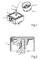
- FIG. 1 is shown in perspective an operating element 1 according to the prior art.
- the operating element 1 comprises a cylindrical operating part 2, which can be gripped by a user and can be turned to set the operation of the domestic appliance.
- the control panel 2 is pushed or attached to a support rod 3, so that a rotationally fixed connection is formed.
- the support rod 3 is coupled to a corresponding electronics 4 in a housing 5, so that, depending on the rotation of the operating part 2, the analog rotation of the support rod 3 is effected about its axis A and this can be detected by the electronics 4.
- Fig. 2 is a sectional view of the control unit 2 with the support rod 3 shown in the connected state.
- the hollow operating part 2 comprises a receiving part 6, in which the holding rod 3 hineinerstreckt.
- a leaf spring 7 is also arranged, which bears only on the outer side or shell side 8 of the support rod 3.
- the leaf spring 7 thus presses against the support rod 3.
- An inventive control element for a domestic appliance comprises a tangible control panel, which is rotatably connected to a support rod and is rotatable about the longitudinal axis of the support rod.
- the operating element further comprises a retaining spring, which is biased against a shell side of the support rod.
- An essential component of the invention is that an indentation is formed on the shell side into which a barb formed on the spring extends.
- the spring is a leaf spring.
- the spring has an arcuately arched base in which the tongue-like barb is formed.
- the curved base is biased supported on a region of the lateral surface, which is formed laterally of the recess.
- These arched arch parts of the base thus do not extend into the indentation, but lie virtually at the edge thereto or on the lateral surface delimiting this indentation.
- the mechanical coupling with respect to The rotational security on the one hand and the generation of the larger maximum withdrawal force can be favored on the other hand in an advantageous manner.
- the indentation in the axial direction has an outwardly oriented boundary wall at the front and at the rear.
- the barb is located with its outer side on the upper edge of the rear boundary wall (viewed from the front in the control panel arranged end of the support rod from). The barb is when attaching the keypad on the support rod on this edge pushed and thereby pressed into the recess. He snaps with its front free end over the upper edge of the front boundary wall into the recess and then rests with the outside on the upper edge of the rear boundary wall. He is thus pressed in a relation to the unloaded inclined basic position in the direction of the bow parts and thus biased. This results in a defined Abziehskraftschwellwert.
- the spring is arranged in a receiving part of the operating part, and is supported therein.
- This receiving part is integrally formed on the control panel.
- the control panel is a cylindrical rotary knob in its advantageous embodiment.
- the operating element 15 comprises a cylindrical operating part 16, which is formed hollow inside in some areas.
- a support rod 17 extends into the interior 18 of the control panel 16 from the rear side.
- a front part 19 of the operating part 16 covers the holding rod 17 from the front, so that it is not visible when looking at the domestic appliance 9 front.
- the holding rod 17 is formed with a circumferential or at least partially encircling bead, which also ensures such a dismantling safety.
- the bonding of the control panel 16 may be provided with the support rod 17, or plug a wedge in the support rod 17, which spreads during assembly of the control panel 16 to the support rod 17 and thereby also ensures a corresponding backup in the axial direction.
Landscapes
- Engineering & Computer Science (AREA)
- General Physics & Mathematics (AREA)
- Combustion & Propulsion (AREA)
- Mechanical Engineering (AREA)
- General Engineering & Computer Science (AREA)
- Physics & Mathematics (AREA)
- Chemical & Material Sciences (AREA)
- Automation & Control Theory (AREA)
- Induction Heating Cooking Devices (AREA)
- Percussion Or Vibration Massage (AREA)
- Finger-Pressure Massage (AREA)
- Domestic Plumbing Installations (AREA)
- Cookers (AREA)
Abstract
Description
- Die Erfindung betrifft ein Bedienelement für ein Hausgerät, mit einem greifbaren Bedienteil, welches mit einer Haltestange drehfest verbunden ist, und um die Längsachse der Haltestange drehbar ist. Das Bedienelement umfasst eine Haltefeder, welche einer Mantelseite der Haltestange vorgespannt anliegt. Des Weiteren betrifft die Erfindung ein Hausgerät mit einer Bedienvorrichtung und einem entsprechenden Bedienelement.
- Hausgeräte, wie beispielsweise Backöfen, weisen eine Bedienvorrichtung auf, die ein oder mehrere Bedienelemente als Drehknebel umfassen. Durch Drehen dieser nach außen stehenden Drehknebel, die üblicherweise zylinderförmig ausgestaltet sind, können Betriebseinstellungen des Hausgeräts erreicht werden. So können beispielsweise Kochzonen ausgewählt und die Kochstufen eingestellt werden. Darüber hinaus können Programmabläufe eingestellt und durchgeführt werden, und beispielsweise auch das Backrohr entsprechend betrieben und aufgeheizt werden.
- In
Fig. 1 ist in perspektivischer Darstellung ein Bedienelement 1 gemäß dem Stand der Technik gezeigt. Das Bedienelement 1 umfasst ein zylinderförmiges Bedienteil 2, welches von einem Nutzer gegriffen werden kann und zur Betriebseinstellung des Hausgeräts gedreht werden kann. Das Bedienteil 2 ist an einer Haltestange 3 aufgeschoben bzw. aufgesteckt, so dass eine drehfeste Verbindung ausgebildet ist. Die Haltestange 3 ist mit einer entsprechenden Elektronik 4 in einem Gehäuse 5 gekoppelt, so dass abhängig von der Drehung des Bedienteils 2 die analoge Drehung der Haltestange 3 um ihre Achse A bewirkt wird und dies über die Elektronik 4 erfasst werden kann. InFig. 2 ist eine Schnittdarstellung des Bedienteils 2 mit der Haltestange 3 im verbundenen Zustand gezeigt. Das hohle Bedienteil 2 umfasst einen Aufnahmeteil 6, in den sich die Haltestange 3 hineinerstreckt. In diesem Aufnahmeteil 6 ist darüber hinaus eine Blattfeder 7 angeordnet, die nur an der Außenseite bzw. Mantelseite 8 der Haltestange 3 anliegt. Die Blattfeder 7 drückt somit gegen die Haltestange 3. Durch diese Kraft entsteht beim Abziehen des Bedienteils 3 eine Reibkraft, die überwunden werden muss. Es liegt hier lediglich eine kraftschlüssige Verbindung vor, die mit einer mechanischen Stabilität beschränkt ist, und daher neuen Anforderungen im Hinblick auf die Abziehstabilität nur bedingt genügt. - Es ist Aufgabe der vorliegenden Erfindung, ein Bedienelement für ein Hausgerät sowie ein Hausgerät mit einer Bedienvorrichtung mit einem Bedienelement zu schaffen, bei welchem bzw. bei welcher ein unerwünschtes Abziehen des Bedienteils von der Haltestange verhindert werden kann.
- Diese Aufgabe wird durch ein Bedienelement und ein Hausgerät gemäß den unabhängigen Ansprüchen gelöst.
- Ein erfindungsgemäßes Bedienelement für ein Hausgerät umfasst ein greifbares Bedienteil, welches mit einer Haltestange drehfest verbunden ist und um die Längsachse der Haltestange drehbar ist. Das Bedienelement umfasst darüber hinaus eine Haltefeder, welche an einer Mantelseite der Haltestange vorgespannt anliegt. Ein wesentlicher Bestandteil der Erfindung liegt darin, dass an der Mantelseite eine Einbuchtung ausgebildet ist, in welche sich ein an der Feder ausgebildeter Widerhaken hineinerstreckt. Durch eine derartige Ausgestaltung kann neben einer drehfesten Verbindung auch eine in axialer Richtung wesentlich verbesserte Haltevorrichtung zwischen dem Bedienteil und der Haltestange erzielt werden. Anforderungen an höhere Abziehkräfte, die ein Lösen des Bedienteils von der Haltestange bewirken, kann damit Rechnung getragen werden.
- Vorzugsweise ist vorgesehen, dass die Feder eine Blattfeder ist.
- In vorteilhafterweise ist vorgesehen, dass die Feder eine bogenförmig gewölbte Basis aufweist, in welcher der zungenartige Widerhaken ausgebildet ist. Durch diese ganz spezifische Ausgestaltung der Feder kann einerseits eine entsprechende radiale Anpresskraft an die Haltestange erzeugt werden und darüber hinaus durch das Widerhakenelement eine axiale Sicherungen bis zu einer gewünschten Abreißkraft erreicht werden. Mit dieser Ausgestaltung der Feder ist somit eine duale Bewegungssicherung gewährleistet.
- Vorzugsweise erstreckt sich der Widerhaken in seiner Endposition mit seinem freien vorderen Ende in Richtung einer vorderen Begrenzungswand in der Einbuchtung, insbesondere ist er so positioniert, dass er bei einem axialen Abziehen des Bedienteils von der Haltestange mit dem freien Ende an der vorderen Begrenzungswand anschlägt. Dadurch wird eine axiale Abziehsicherung erreicht, die hohen Abzugskräften standhält.
- Vorzugsweise ist vorgesehen, dass die Feder zwei beabstandet zueinander zugeordnete gleich gewölbte Bauteile aufweist, zwischen denen sich der Widerhaken geradlinig schräg nach oben erstreckt. Dies gewährleistet eine besonders hervorzuhebende Ausführung, da dadurch quasi in Längsrichtung der Feder eine symmetrische Ausgestaltung erzielt werden kann. Dies bewirkt eine besonders gleichmäßige Erzeugung einer Krafteinwirkung von der Feder auf die Haltestange.
- Der Widerhaken kann auch als plattenartiger, biegbarer Abziehstreifen bezeichnet werden.
- Vorzugsweise ist vorgesehen, dass der Widerhaken an einen unterhalb des Maximums der Bodenform quer verlaufenden Verbindungssteg zwischen den beiden Bogenteilen mündet. Dadurch kann die Stabilität des Widerhakens verbessert und durch die schräg orientierte Anordnung eine definierte und ausreichende Abzugskraftstabilisierung erreicht werden. Dies insbesondere im Hinblick auf die Kombination mit der gewählten Struktur der Bogenteile.
- Vorzugsweise ist vorgesehen, dass sich die gewölbte Basis an einen Bereich der Mantelfläche vorgespannt abstützt, der seitlich der Einbuchtung ausgebildet ist. Diese gewölbten Bogenteile der Basis erstrecken sich somit nicht in die Einbuchtung hinein, sondern liegen quasi am Rand dazu bzw. an der diese Einbuchtung begrenzende Mantelfläche an. Auch hierzu kann in vorteilhafterweise somit die mechanische Kopplung bzgl. der Drehsicherung einerseits und der Erzeugung der größeren maximalen Abzugskraft andererseits begünstigt werden.
- Insbesondere ist vorgesehen, dass die Einbuchtung in axialer Richtung vorne und hinten jeweils eine nach außen orientierte Begrenzungswand aufweist. Insbesondere liegt der Widerhaken mit seiner Außenseite an der oberen Kante der hinteren Begrenzungswand (vom vorderen im Bedienteil angeordneten Ende der Haltestange aus betrachtet) an. Der Widerhaken wird beim Aufstecken des Bedienteils auf die Haltestange über diese Kante geschoben und dadurch in die Einbuchtung hinein gedrückt. Er schnappt mit seinem vorderen freien Ende über die obere Kante der vorderen Begrenzungswand über in die Einbuchtung und liegt mit der Außenseite dann an der oberen Kante der hinteren Begrenzungswand an. Er ist dadurch in einer gegenüber der unbelasteten schräg gestellten Grundstellung in Richtung der Bogenteile gedrückt und somit vorgespannt. Dadurch ergibt sich eine definierter Abzugskraftschwellwert.
- Vorzugsweise ist vorgesehen, dass die Feder, insbesondere der Widerhaken so ausgebildet ist, dass eine axiale Abzugskraft des Bedienteils von der Haltestange größer oder gleich 50 N, insbesondere zwischen 50 N und 60 N ist, wenn das Bedienteil an der Haltestange montiert ist.
- Mit dieser ganz wertspezifischen Angabe der Abziehungskraft können hohe Anforderungen an die Sicherheit erfüllt werden.
- Vorzugsweise ist die Feder in einem Aufnahmeteil des Bedienteils angeordnet, und stützt sich darin ab. Dieses Aufnahmeteil ist integral am Bedienteil ausgebildet.
- Das Bedienteil ist ein zylinderförmiger Drehknebel in seiner vorteilhaften Ausgestaltung.
- Darüber hinaus betrifft die Erfindung auch ein Hausgerät mit einer Bedienvorrichtung, welche zumindest ein erfindungsgemäßes Bedienelement und eine vorteilhafte Ausgestaltung davon aufweist.
- Ein Ausführungsbeispiel der Erfindung wird nachfolgend anhand schematischer Zeichnungen näher erläutert. Es zeigen:
- Fig. 1
- eine perspektivische Darstellung eines aus dem Stand der Technik bekannten Bedienelements;
- Fig. 2
- eine Schnittdarstellung des Bedienelements gemäß
Fig. 1 ; - Fig. 3
- ein Ausführungsbeispiel eines erfindungsgemäßen Hausgeräts;
- Fig. 4
- eine Schnittdarstellung eines Ausführungsbeispiels eines erfindungsgemäßen Bedienelements; und
- Fig. 5
- eine perspektivische Darstellung einer Feder des Bedienelements gemäß
Fig. 4 . - In den Figuren werden gleiche oder funktionsgleiche Elemente mit den gleichen Bezugszeichen versehen.
- In
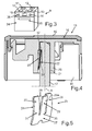
Fig. 3 ist in einer perspektivischen Darstellung ein als Backofen ausgebildetes Hausgerät 9 gezeigt. Dieses weist eine Mehrzahl von sowohl anzahlmäßig als auch positionsmäßig beispielhaften Kochzonen 10, 11, 12 und 13 auf. Darüber hinaus ist ein durch eine Tür 34 verschlossener Garraum 35 vorgesehen. Des Weiteren umfasst das Hausgerät 9 eine Bedienvorrichtung 36, die auch wiederum positionell als anzahlmäßig beispielhaft eine Anzeigeeinheit 14 und Bedienelemente 15 und 16 aufweist. Die Bedienelemente 15 und 16 sind als Drehknebel ausgebildet und können um ihre Längsachse gedreht werden, wodurch Betriebseinstellungen des Hausgeräts 9 erfolgen. - In
Fig. 4 in einer Schnittdarstellung ein Ausführungsbeispiel des Bedienelements 15 gezeigt. Das Bedienelement 15 umfasst ein zylinderförmiges Bedienteil 16, welches innen bereichsweise hohl ausgebildet ist. Eine Haltestange 17 erstreckt sich in das Innere 18 des Bedienteils 16 von der rückwärtigen Seite her. Ein Frontteil 19 des Bedienteils 16 deckt die Haltestange 17 von vorne ab, so dass sie bei Betrachtung des Hausgeräts 9 frontseitig nicht zu erkennen ist. - Im Inneren 18 ist darüber hinaus ein Aufnahmeteil 20 angeordnet, welches zur Aufnahme des vorderen Endes der Haltestange 17 ausgebildet ist.
- In der Darstellung gemäß
Fig. 4 ist die Haltestange 17 im montierten Endzustand in dem Aufnahmeteil 20 gezeigt. Die Haltestange 17 ist insbesondere als runder Stab ausgebildet, welcher an seiner Mantelseite 21 eine Einbuchtung 22 aufweist. Die Einbuchtung 22 ist zur Aufnahme des Teilelements einer Feder 23, die ebenfalls im Aufnahmeteil 20 angeordnet ist, ausgebildet. Durch die Feder 23 kann die drehfeste Verbindung der Haltestange 17 mit dem Bedienteil 16 gewährleistet werden, so dass eine Relativdrehung der beiden Bauteile um die Achse A vermieden ist. Darüber hinaus wird durch die spezifische Ausgestaltung der Feder 23 erreicht, dass ein Abziehen des Bedienteils 16 von der Haltestange 17 in Richtung der Achse A erst ab Abzugskräften größer 50 N erfolgt. - Die Feder 23 ist in
Fig. 5 in perspektivischer Darstellung gezeigt. Sie weist eine bogenförmige Basis 24 auf, wobei diesbezüglich zwei stetig gekrümmte Bogenteile 25 und 26 ausgebildet sind. Die Bogenteile 25 und 26 sind beabstandet zueinander angeordnet und über einen quer verlaufenden Verbindungssteg 27 miteinander verbunden. In einem Freiraum 28 zwischen den beiden Bogenteile 25 und 26 ist ein plattenartiger, biegbarer Abzugstreifen in Form eines Widerhakens 29 angeordnet. Dieser ist beabstandet zu den beiden Bogenteilen 25 und 26 positioniert und verläuft im Wesentlichen geradlinig. Er ist an den Verbindungssteg 27 einstückig ausgebildet, wobei die gesamte Feder 23 einstückig ausgestaltet ist. Die Orientierung des Widerhakens 29, der zungenförmig ausgestaltet ist, ist schräg nach oben orientiert, wobei die Mündung 30 des Widerhakens 29 an dem Verbindungssteg 27 unterhalb eines Maximums 31 der beiden Bogenteile 25 und 26 angeordnet ist. - Wie aus der Darstellung in
Fig. 4 zu erkennen ist, liegen die Bogenteile 25 und 26 außerhalb der Einbuchtung 22 an der Mantelfläche 21 an. Der Widerhaken 29 hingegen erstreckt sich in den Bereich der Einbuchtung 22 hinein. Er liegt in seiner Endposition mit einer Außenseite 29a an einer oberen Kante einer hinteren Begrenzungswand 33 der Einbuchtung 22 an. Dadurch wird er gegenüber seiner unbelasteten Grundstellung, wie sie inFig. 5 gezeigt ist, vorgespannt. Des Weiteren zeigt sein vorderes freies Ende in Richtung einer vorderen Begrenzungswand 32 der Einbuchtung 22. Beim Axialen Abziehen schlägt das freie Ende des Widerhakens 29 an dieser vorderen Begrenzungswand 32 an und verhindert ein Abziehen bis zu einer definierten Abzugskraft. Erst wenn mit einer größeren Kraft angezogen wird, wird der Widerhaken 29 verformt und das Bedienteil 16 löst sich von der Haltestange 17. - Durch Abziehen des Bedienteils 16 wird durch die spezifische Neigung des Widerhakens 29 und deren Ausgestaltung im Hinblick auf Material und Dicke eine gewisse Gegenkraft erzeugt, wodurch auch der Schwellwert für die Abzugskraft definiert werden kann.
- In der in der
Fig. 4 gezeigten Endposition der Feder 23 sind die bogenförmigen Teile 25 und 26 etwas zusammengedrückt und daher vorgespannt und liegen somit in vorgespannter Weise an der Mantelseite 21 an und stützen sich an der Innenwand des Aufnahmeteils 20 ab. - In
Fig. 5 ist der separate Zustand gezeigt, bei dem die Krümmung der Bogenteile 25 und 26 stärker ist, da sie im Vergleich zur Ausgestaltung inFig. 4 nicht zusammengedrückt sind. - Durch die Feder 23, insbesondere mit dem Widerhaken 29, wird eine Demontagesicherungseinrichtung für das Bedienteil 16 gewährleistet.
- Alternativ kann auch vorgesehen sein, dass die Haltestange 17 mit einer umlaufenden oder zumindest teilweise umlaufenden Wulst ausgebildet ist, die ebenfalls eine derartige Demontagesicherung gewährleistet. Alternativ kann auch die Verklebung des Bedienteils 16 mit der Haltestange 17 vorgesehen sein, oder ein Keil in der Haltestange 17 stecken, der bei der Montage des Bedienteils 16 an die Haltestange 17 sich aufspreizt und dadurch ebenfalls eine entsprechende Sicherung in axialer Richtung gewährleistet.
-
- 1
- Bedienelement
- 2
- Bedienteil
- 3
- Haltestange
- 4
- Elektronik
- 5
- Gehäuse
- 6
- Aufnahmeteil
- 7
- Blattfeder
- 8
- Mantelseite
- 9
- Hausgerät
- 10, 11, 12, 13
- Kochzonen
- 14
- Anzeigeeinheit
- 15, 16
- Bedienelemente
- 17
- Haltestange
- 18
- Inneres
- 19
- Frontteil
- 20
- Aufnahmeteil
- 21
- Mantelseite
- 22
- Einbuchtung
- 23
- Feder
- 24
- Basis
- 25, 26
- Bogenteil
- 27
- Verbindungssteg
- 28
- Freiraum
- 29
- Widerhaken
- 29a
- Außenseite
- 30
- Mündung
- 31
- Maximum
- 32, 33
- Begrenzungswände
- 34
- Tür
- 35
- Garraum
- 36
- Bedienvorrichtung
Claims (13)
- Bedienelement (1, 15) für ein Hausgerät (9), mit einem greifbaren Bedienteil (2, 16), welches mit einer Haltestange (3, 17) drehfest verbunden ist und um die Längsachse (A) der Haltestange (3, 17) zur Einstellung von Betriebsbedingungen drehbar ist, und eine Haltefeder (7, 23) an eine Mantelseite (8, 21) der Haltestange (3, 17) vorgespannt anliegt, dadurch gekennzeichnet, dass an der Mantelseite (21) eine Einbuchtung (22) ausgebildet ist, in welche sich ein an der Feder (23) ausgebildeter Widerhaken (29) hineinerstreckt.
- Bedienelement nach Anspruch 1, dadurch gekennzeichnet, dass die Einbuchtung (22) eine hintere Begrenzungswand (33) aufweist, an deren oberer Kante der Widerhaken (29) mit seiner Außenseite (29a) in seiner Endposition anliegt und vorgespannt ist.
- Bedienelement nach Anspruch 1 oder 2, dadurch gekennzeichnet, dass sich der Widerhaken (29) in seiner Endposition mit seinem freien vorderen Ende in Richtung einer vorderen Begrenzungswand (32) in der Einbuchtung (22) erstreckt, insbesondere so positioniert ist, dass er bei einem axialen Abziehen des Bedienteils (16) von der Haltestange (17) mit dem freien Ende an der vorderen Begrenzungswand (32) anschlägt.
- Bedienelement nach einem der vorhergehenden Ansprüche, dadurch gekennzeichnet, dass die Feder (23) eine Blattfeder ist.
- Bedienelement nach einem der vorhergehenden Ansprüche, dadurch gekennzeichnet, dass die Feder (23) eine bogenförmig gewölbte Basis (24) aufweist, in welcher der zungenartige Widerhaken (29) ausgebildet ist.
- Bedienelement nach einem der vorhergehenden Ansprüche, dadurch gekennzeichnet, dass die Feder (23) zwei beabstandet zueinander angeordnete, gleich gewölbte Bogenteile (25, 26) aufweist, zwischen denen sich der Widerhaken (29) geradlinig schräg nach oben erstreckt.
- Bedienelement nach Anspruch 6, dadurch gekennzeichnet, dass der Widerhaken (29) an einen unterhalb des Maximums (31) der Bogenform quer verlaufenden Verbindungssteg (27) zwischen den beiden Bogenteilen (25, 26) mündet.
- Bedienelement nach einem der vorhergehenden Ansprüche 5 bis 7, dadurch gekennzeichnet, dass sich die gewölbte Basis (24) an einem Bereich der Mantelseite (21) vorgespannt abstützt, der seitlich der Einbuchtung (22) ausgebildet ist.
- Bedienelement nach einem der vorhergehenden Ansprüche, dadurch gekennzeichnet, dass der Widerhaken (29) ein plattenartiger biegbarer Streifen ist.
- Bedienelement nach einem der vorhergehenden Ansprüche, dadurch gekennzeichnet, dass die Feder (23), insbesondere der Widerhaken (29), so ausgebildet ist, dass eine axiale Abzugskraft des Bedienteils (16) von der Haltestange (17) größer oder gleich 50 N, insbesondere zwischen 50N und 60N, ist.
- Bedienelement nach einem der vorhergehenden Ansprüche, dadurch gekennzeichnet, dass die Feder (23) in einem Aufnahmeteil (20) im Inneren (18) des hohlen Bedienteils (16) angeordnet ist.
- Bedienelement nach einem der vorhergehenden Ansprüche, dadurch gekennzeichnet, dass das Bedienteil (16) ein zylinderförmiger Drehknebel ist.
- Hausgerät (9) mit einer Bedienvorrichtung (13), welche zumindest ein Bedienelement (15, 16) nach den vorhergehenden Ansprüche aufweist.
Applications Claiming Priority (1)
| Application Number | Priority Date | Filing Date | Title |
|---|---|---|---|
| DE201110076096 DE102011076096A1 (de) | 2011-05-19 | 2011-05-19 | Bedienelement für ein Hausgerät sowie Hausgerät mit einer Bedienvorrichtung mit einem Bedienelement |
Publications (3)
| Publication Number | Publication Date |
|---|---|
| EP2527951A2 true EP2527951A2 (de) | 2012-11-28 |
| EP2527951A3 EP2527951A3 (de) | 2013-07-10 |
| EP2527951B1 EP2527951B1 (de) | 2015-07-15 |
Family
ID=46245822
Family Applications (1)
| Application Number | Title | Priority Date | Filing Date |
|---|---|---|---|
| EP12168214.0A Active EP2527951B1 (de) | 2011-05-19 | 2012-05-16 | Bedienelement für ein Hausgerät sowie Hausgerät mit einer Bedienvorrichtung mit einem Bedienelement |
Country Status (3)
| Country | Link |
|---|---|
| EP (1) | EP2527951B1 (de) |
| DE (1) | DE102011076096A1 (de) |
| ES (1) | ES2544928T3 (de) |
Cited By (5)
| Publication number | Priority date | Publication date | Assignee | Title |
|---|---|---|---|---|
| FR3002335A1 (fr) * | 2013-02-19 | 2014-08-22 | Continental Automotive France | Dispositif de commande avec tenue a l'arrachement |
| DE102014202442A1 (de) | 2014-02-11 | 2015-08-13 | BSH Hausgeräte GmbH | Schalteranordnung für Haushaltsgeräte |
| EP2952817A1 (de) * | 2014-05-28 | 2015-12-09 | BSH Hausgeräte GmbH | Hausgeräte-bedienanordnung, gasventil und herd |
| EP3428496A1 (de) * | 2017-07-12 | 2019-01-16 | Grohe AG | Bedienelement sowie eine das bedienelement aufweisende baueinheit |
| LU103312B1 (de) * | 2024-06-11 | 2025-12-11 | Miele & Cie | Bedieneinrichtung für eine Gareinrichtung |
Families Citing this family (1)
| Publication number | Priority date | Publication date | Assignee | Title |
|---|---|---|---|---|
| DE102014226434A1 (de) | 2014-12-18 | 2016-06-23 | BSH Hausgeräte GmbH | Sicherbare Vorrichtung zum Betätigen eines elektronischen Bauteils |
Family Cites Families (3)
| Publication number | Priority date | Publication date | Assignee | Title |
|---|---|---|---|---|
| DE1074117B (de) * | 1960-01-28 | Busch Jaeger Durener Metallwerke Aktiengesellschaft Ludenscheid | Griff fur elektrische Drehschalter | |
| DE579495C (de) * | 1931-03-26 | 1933-06-27 | Rca Corp | Kupplung des Drehknopfes mit der Welle von Abstimmelementen von Rundfunkgeraeten |
| US2774852A (en) * | 1953-11-13 | 1956-12-18 | Hart Mfg Co | Electric switch |
-
2011
- 2011-05-19 DE DE201110076096 patent/DE102011076096A1/de not_active Withdrawn
-
2012
- 2012-05-16 ES ES12168214.0T patent/ES2544928T3/es active Active
- 2012-05-16 EP EP12168214.0A patent/EP2527951B1/de active Active
Non-Patent Citations (1)
| Title |
|---|
| None |
Cited By (8)
| Publication number | Priority date | Publication date | Assignee | Title |
|---|---|---|---|---|
| FR3002335A1 (fr) * | 2013-02-19 | 2014-08-22 | Continental Automotive France | Dispositif de commande avec tenue a l'arrachement |
| WO2014127900A1 (fr) * | 2013-02-19 | 2014-08-28 | Continental Automotive France | Dispositif de commande avec tenue a l'arrachement |
| CN105074605A (zh) * | 2013-02-19 | 2015-11-18 | 法国大陆汽车公司 | 具有拔出阻力的控制装置 |
| DE102014202442A1 (de) | 2014-02-11 | 2015-08-13 | BSH Hausgeräte GmbH | Schalteranordnung für Haushaltsgeräte |
| DE102014202442B4 (de) | 2014-02-11 | 2024-03-28 | BSH Hausgeräte GmbH | Schalteranordnung für Haushaltsgeräte |
| EP2952817A1 (de) * | 2014-05-28 | 2015-12-09 | BSH Hausgeräte GmbH | Hausgeräte-bedienanordnung, gasventil und herd |
| EP3428496A1 (de) * | 2017-07-12 | 2019-01-16 | Grohe AG | Bedienelement sowie eine das bedienelement aufweisende baueinheit |
| LU103312B1 (de) * | 2024-06-11 | 2025-12-11 | Miele & Cie | Bedieneinrichtung für eine Gareinrichtung |
Also Published As
| Publication number | Publication date |
|---|---|
| ES2544928T3 (es) | 2015-09-07 |
| EP2527951B1 (de) | 2015-07-15 |
| EP2527951A3 (de) | 2013-07-10 |
| DE102011076096A1 (de) | 2012-11-22 |
Similar Documents
| Publication | Publication Date | Title |
|---|---|---|
| EP2527951B1 (de) | Bedienelement für ein Hausgerät sowie Hausgerät mit einer Bedienvorrichtung mit einem Bedienelement | |
| EP2049807B1 (de) | Vorrichtung zum befestigen eines anbauteiles und eines trägerteiles in einem abstand voneinander | |
| DE202018006525U1 (de) | Dunstabzugsvorrichtung zum Abzug von Kochdünsten nach unten | |
| DE102007009616B4 (de) | Befestigungseinheit | |
| EP3183499B1 (de) | Bedienvorrichtung für ein haushaltsgerät mit einem bedienelement und einem im bedienelement ausgebildeten anzeigebereich | |
| DE102012222146B4 (de) | Bedienelement für ein Haushaltsgerät mit einem Stützelement und einem Führungselement, Bedienvorrichtung mit einem derartigen Bedienelement sowie Haushaltsgerät mit einer Bedienvorrichtung | |
| EP2390575A2 (de) | Gasventil mit einem Betätigungselement für einen elektrischen Schalter | |
| EP3015946A2 (de) | Haushaltsgerät, insbesondere durchlauferhitzer | |
| EP2620831A2 (de) | Bedienelement für ein Ventil, Ventil, Kombination von Bedienelement und Ventil sowie Haushaltsgerät | |
| EP3211324A1 (de) | Lagerbuchse für ein haushaltsgerät mit einem federelement, welches ein abdeckteil zum abdecken einer einfädelöffnung aufweist, baugruppe sowie haushaltsgerät | |
| EP2952817B1 (de) | Gasventil mit einer Hausgeräte-Bedienanordnung und Herd | |
| WO2020212161A1 (de) | Lagerbuchse für ein haushaltsgerät mit einem grundkörper und einer hülse mit radialem federelement, baugruppe sowie haushaltsgerät | |
| DE202016102116U1 (de) | Befestigungsanordnung für die Befestigung einer Flanschplatte an einem Schaltschrankgehäuse und ein entsprechendes Schaltschrankgehäuse | |
| DE102013109707B4 (de) | Zugmittelbefestigungseinrichtung für ein Haushaltgerät, Haushaltgerät und Verfahren | |
| EP4166852A2 (de) | Haushaltsgerätevorrichtung, haushaltsgerät, haushaltsgeräte-system, baukastensystem zur zusammenstellung einer haus-haltsgerätevorrichtung und verfahren zur fixierung eines haushaltsgeräts | |
| EP1505351B1 (de) | Gargerät mit einer Beleuchtungseinrichtung | |
| DE102014100414B4 (de) | Dunstabzugshaubeneinrichtung | |
| EP2138770A2 (de) | Haushaltsgerät, insbesondere Dunstabzugshaube, mit einem Scharnier und Scharnier für ein Haushaltsgerät | |
| EP2740871B1 (de) | Vorrichtung für ein Haushaltsgerät mit einem Scharnier und einer Koppeleinrichtung sowie Haushaltsgerät mit einer derartigen Vorrichtung | |
| EP3096085B1 (de) | Haushaltgeräte-Bedienanordnung, Gasventil und Gaskochstelle | |
| DE102018200585A1 (de) | Beleuchtungsvorrichtung für ein Gargerät mit einer Haltelasche in einem spezifischen Freischnitt eines Gehäuseteils, sowie Gargerät | |
| DE10161539A1 (de) | Aufnahme mit einer Achse zur Drehbedienung eines Schaltgeräts o. dgl. | |
| DE102006000898B4 (de) | Abdeckanordnung für ein Haushaltsgerät zur Abdeckung eines Teils eines Haushaltgeräts mit einer Halterung und einem Abdeckteil | |
| EP2136145A2 (de) | Knebel für ein Haushaltsgerät | |
| EP2357414B1 (de) | Hausgerät zum Zubereiten von Lebensmitteln mit einer Lagerbuchse |
Legal Events
| Date | Code | Title | Description |
|---|---|---|---|
| PUAI | Public reference made under article 153(3) epc to a published international application that has entered the european phase |
Free format text: ORIGINAL CODE: 0009012 |
|
| AK | Designated contracting states |
Kind code of ref document: A2 Designated state(s): AL AT BE BG CH CY CZ DE DK EE ES FI FR GB GR HR HU IE IS IT LI LT LU LV MC MK MT NL NO PL PT RO RS SE SI SK SM TR |
|
| AX | Request for extension of the european patent |
Extension state: BA ME |
|
| PUAL | Search report despatched |
Free format text: ORIGINAL CODE: 0009013 |
|
| AK | Designated contracting states |
Kind code of ref document: A3 Designated state(s): AL AT BE BG CH CY CZ DE DK EE ES FI FR GB GR HR HU IE IS IT LI LT LU LV MC MK MT NL NO PL PT RO RS SE SI SK SM TR |
|
| AX | Request for extension of the european patent |
Extension state: BA ME |
|
| RIC1 | Information provided on ipc code assigned before grant |
Ipc: F24C 7/08 20060101ALI20130603BHEP Ipc: G05G 1/12 20060101AFI20130603BHEP |
|
| 17P | Request for examination filed |
Effective date: 20140110 |
|
| RBV | Designated contracting states (corrected) |
Designated state(s): AL AT BE BG CH CY CZ DE DK EE ES FI FR GB GR HR HU IE IS IT LI LT LU LV MC MK MT NL NO PL PT RO RS SE SI SK SM TR |
|
| GRAP | Despatch of communication of intention to grant a patent |
Free format text: ORIGINAL CODE: EPIDOSNIGR1 |
|
| INTG | Intention to grant announced |
Effective date: 20150213 |
|
| RAP1 | Party data changed (applicant data changed or rights of an application transferred) |
Owner name: BSH HAUSGERAETE GMBH |
|
| GRAS | Grant fee paid |
Free format text: ORIGINAL CODE: EPIDOSNIGR3 |
|
| GRAA | (expected) grant |
Free format text: ORIGINAL CODE: 0009210 |
|
| AK | Designated contracting states |
Kind code of ref document: B1 Designated state(s): AL AT BE BG CH CY CZ DE DK EE ES FI FR GB GR HR HU IE IS IT LI LT LU LV MC MK MT NL NO PL PT RO RS SE SI SK SM TR |
|
| REG | Reference to a national code |
Ref country code: CH Ref legal event code: EP Ref country code: GB Ref legal event code: FG4D Free format text: NOT ENGLISH |
|
| REG | Reference to a national code |
Ref country code: IE Ref legal event code: FG4D Free format text: LANGUAGE OF EP DOCUMENT: GERMAN |
|
| REG | Reference to a national code |
Ref country code: AT Ref legal event code: REF Ref document number: 737098 Country of ref document: AT Kind code of ref document: T Effective date: 20150815 |
|
| REG | Reference to a national code |
Ref country code: DE Ref legal event code: R096 Ref document number: 502012003783 Country of ref document: DE |
|
| REG | Reference to a national code |
Ref country code: ES Ref legal event code: FG2A Ref document number: 2544928 Country of ref document: ES Kind code of ref document: T3 Effective date: 20150907 |
|
| REG | Reference to a national code |
Ref country code: NL Ref legal event code: MP Effective date: 20150715 |
|
| REG | Reference to a national code |
Ref country code: LT Ref legal event code: MG4D |
|
| PG25 | Lapsed in a contracting state [announced via postgrant information from national office to epo] |
Ref country code: GR Free format text: LAPSE BECAUSE OF FAILURE TO SUBMIT A TRANSLATION OF THE DESCRIPTION OR TO PAY THE FEE WITHIN THE PRESCRIBED TIME-LIMIT Effective date: 20151016 Ref country code: LT Free format text: LAPSE BECAUSE OF FAILURE TO SUBMIT A TRANSLATION OF THE DESCRIPTION OR TO PAY THE FEE WITHIN THE PRESCRIBED TIME-LIMIT Effective date: 20150715 Ref country code: NO Free format text: LAPSE BECAUSE OF FAILURE TO SUBMIT A TRANSLATION OF THE DESCRIPTION OR TO PAY THE FEE WITHIN THE PRESCRIBED TIME-LIMIT Effective date: 20151015 Ref country code: FI Free format text: LAPSE BECAUSE OF FAILURE TO SUBMIT A TRANSLATION OF THE DESCRIPTION OR TO PAY THE FEE WITHIN THE PRESCRIBED TIME-LIMIT Effective date: 20150715 Ref country code: LV Free format text: LAPSE BECAUSE OF FAILURE TO SUBMIT A TRANSLATION OF THE DESCRIPTION OR TO PAY THE FEE WITHIN THE PRESCRIBED TIME-LIMIT Effective date: 20150715 |
|
| PG25 | Lapsed in a contracting state [announced via postgrant information from national office to epo] |
Ref country code: PL Free format text: LAPSE BECAUSE OF FAILURE TO SUBMIT A TRANSLATION OF THE DESCRIPTION OR TO PAY THE FEE WITHIN THE PRESCRIBED TIME-LIMIT Effective date: 20150715 Ref country code: RS Free format text: LAPSE BECAUSE OF FAILURE TO SUBMIT A TRANSLATION OF THE DESCRIPTION OR TO PAY THE FEE WITHIN THE PRESCRIBED TIME-LIMIT Effective date: 20150715 Ref country code: SE Free format text: LAPSE BECAUSE OF FAILURE TO SUBMIT A TRANSLATION OF THE DESCRIPTION OR TO PAY THE FEE WITHIN THE PRESCRIBED TIME-LIMIT Effective date: 20150715 Ref country code: PT Free format text: LAPSE BECAUSE OF FAILURE TO SUBMIT A TRANSLATION OF THE DESCRIPTION OR TO PAY THE FEE WITHIN THE PRESCRIBED TIME-LIMIT Effective date: 20151116 Ref country code: HR Free format text: LAPSE BECAUSE OF FAILURE TO SUBMIT A TRANSLATION OF THE DESCRIPTION OR TO PAY THE FEE WITHIN THE PRESCRIBED TIME-LIMIT Effective date: 20150715 |
|
| REG | Reference to a national code |
Ref country code: DE Ref legal event code: R097 Ref document number: 502012003783 Country of ref document: DE |
|
| PG25 | Lapsed in a contracting state [announced via postgrant information from national office to epo] |
Ref country code: SK Free format text: LAPSE BECAUSE OF FAILURE TO SUBMIT A TRANSLATION OF THE DESCRIPTION OR TO PAY THE FEE WITHIN THE PRESCRIBED TIME-LIMIT Effective date: 20150715 Ref country code: EE Free format text: LAPSE BECAUSE OF FAILURE TO SUBMIT A TRANSLATION OF THE DESCRIPTION OR TO PAY THE FEE WITHIN THE PRESCRIBED TIME-LIMIT Effective date: 20150715 Ref country code: CZ Free format text: LAPSE BECAUSE OF FAILURE TO SUBMIT A TRANSLATION OF THE DESCRIPTION OR TO PAY THE FEE WITHIN THE PRESCRIBED TIME-LIMIT Effective date: 20150715 Ref country code: DK Free format text: LAPSE BECAUSE OF FAILURE TO SUBMIT A TRANSLATION OF THE DESCRIPTION OR TO PAY THE FEE WITHIN THE PRESCRIBED TIME-LIMIT Effective date: 20150715 |
|
| PLBE | No opposition filed within time limit |
Free format text: ORIGINAL CODE: 0009261 |
|
| STAA | Information on the status of an ep patent application or granted ep patent |
Free format text: STATUS: NO OPPOSITION FILED WITHIN TIME LIMIT |
|
| REG | Reference to a national code |
Ref country code: FR Ref legal event code: PLFP Year of fee payment: 5 |
|
| PG25 | Lapsed in a contracting state [announced via postgrant information from national office to epo] |
Ref country code: RO Free format text: LAPSE BECAUSE OF FAILURE TO SUBMIT A TRANSLATION OF THE DESCRIPTION OR TO PAY THE FEE WITHIN THE PRESCRIBED TIME-LIMIT Effective date: 20150715 |
|
| 26N | No opposition filed |
Effective date: 20160418 |
|
| PG25 | Lapsed in a contracting state [announced via postgrant information from national office to epo] |
Ref country code: IS Free format text: LAPSE BECAUSE OF FAILURE TO SUBMIT A TRANSLATION OF THE DESCRIPTION OR TO PAY THE FEE WITHIN THE PRESCRIBED TIME-LIMIT Effective date: 20150715 |
|
| PG25 | Lapsed in a contracting state [announced via postgrant information from national office to epo] |
Ref country code: BE Free format text: LAPSE BECAUSE OF NON-PAYMENT OF DUE FEES Effective date: 20160531 Ref country code: SI Free format text: LAPSE BECAUSE OF FAILURE TO SUBMIT A TRANSLATION OF THE DESCRIPTION OR TO PAY THE FEE WITHIN THE PRESCRIBED TIME-LIMIT Effective date: 20150715 |
|
| PG25 | Lapsed in a contracting state [announced via postgrant information from national office to epo] |
Ref country code: LU Free format text: LAPSE BECAUSE OF FAILURE TO SUBMIT A TRANSLATION OF THE DESCRIPTION OR TO PAY THE FEE WITHIN THE PRESCRIBED TIME-LIMIT Effective date: 20160516 |
|
| REG | Reference to a national code |
Ref country code: CH Ref legal event code: PL |
|
| PG25 | Lapsed in a contracting state [announced via postgrant information from national office to epo] |
Ref country code: CH Free format text: LAPSE BECAUSE OF NON-PAYMENT OF DUE FEES Effective date: 20160531 Ref country code: LI Free format text: LAPSE BECAUSE OF NON-PAYMENT OF DUE FEES Effective date: 20160531 |
|
| REG | Reference to a national code |
Ref country code: IE Ref legal event code: MM4A |
|
| REG | Reference to a national code |
Ref country code: FR Ref legal event code: PLFP Year of fee payment: 6 |
|
| PG25 | Lapsed in a contracting state [announced via postgrant information from national office to epo] |
Ref country code: IE Free format text: LAPSE BECAUSE OF NON-PAYMENT OF DUE FEES Effective date: 20160516 |
|
| PG25 | Lapsed in a contracting state [announced via postgrant information from national office to epo] |
Ref country code: NL Free format text: LAPSE BECAUSE OF FAILURE TO SUBMIT A TRANSLATION OF THE DESCRIPTION OR TO PAY THE FEE WITHIN THE PRESCRIBED TIME-LIMIT Effective date: 20150715 |
|
| REG | Reference to a national code |
Ref country code: FR Ref legal event code: PLFP Year of fee payment: 7 |
|
| PG25 | Lapsed in a contracting state [announced via postgrant information from national office to epo] |
Ref country code: CY Free format text: LAPSE BECAUSE OF FAILURE TO SUBMIT A TRANSLATION OF THE DESCRIPTION OR TO PAY THE FEE WITHIN THE PRESCRIBED TIME-LIMIT Effective date: 20150715 Ref country code: SM Free format text: LAPSE BECAUSE OF FAILURE TO SUBMIT A TRANSLATION OF THE DESCRIPTION OR TO PAY THE FEE WITHIN THE PRESCRIBED TIME-LIMIT Effective date: 20150715 Ref country code: HU Free format text: LAPSE BECAUSE OF FAILURE TO SUBMIT A TRANSLATION OF THE DESCRIPTION OR TO PAY THE FEE WITHIN THE PRESCRIBED TIME-LIMIT; INVALID AB INITIO Effective date: 20120516 |
|
| PG25 | Lapsed in a contracting state [announced via postgrant information from national office to epo] |
Ref country code: MC Free format text: LAPSE BECAUSE OF FAILURE TO SUBMIT A TRANSLATION OF THE DESCRIPTION OR TO PAY THE FEE WITHIN THE PRESCRIBED TIME-LIMIT Effective date: 20150715 Ref country code: MT Free format text: LAPSE BECAUSE OF FAILURE TO SUBMIT A TRANSLATION OF THE DESCRIPTION OR TO PAY THE FEE WITHIN THE PRESCRIBED TIME-LIMIT Effective date: 20150715 Ref country code: MK Free format text: LAPSE BECAUSE OF FAILURE TO SUBMIT A TRANSLATION OF THE DESCRIPTION OR TO PAY THE FEE WITHIN THE PRESCRIBED TIME-LIMIT Effective date: 20150715 |
|
| REG | Reference to a national code |
Ref country code: AT Ref legal event code: MM01 Ref document number: 737098 Country of ref document: AT Kind code of ref document: T Effective date: 20170516 |
|
| PG25 | Lapsed in a contracting state [announced via postgrant information from national office to epo] |
Ref country code: BG Free format text: LAPSE BECAUSE OF FAILURE TO SUBMIT A TRANSLATION OF THE DESCRIPTION OR TO PAY THE FEE WITHIN THE PRESCRIBED TIME-LIMIT Effective date: 20150715 |
|
| PG25 | Lapsed in a contracting state [announced via postgrant information from national office to epo] |
Ref country code: AT Free format text: LAPSE BECAUSE OF NON-PAYMENT OF DUE FEES Effective date: 20170516 |
|
| PG25 | Lapsed in a contracting state [announced via postgrant information from national office to epo] |
Ref country code: AL Free format text: LAPSE BECAUSE OF FAILURE TO SUBMIT A TRANSLATION OF THE DESCRIPTION OR TO PAY THE FEE WITHIN THE PRESCRIBED TIME-LIMIT Effective date: 20150715 |
|
| PGFP | Annual fee paid to national office [announced via postgrant information from national office to epo] |
Ref country code: IT Payment date: 20200528 Year of fee payment: 9 |
|
| REG | Reference to a national code |
Ref country code: DE Ref legal event code: R084 Ref document number: 502012003783 Country of ref document: DE |
|
| PG25 | Lapsed in a contracting state [announced via postgrant information from national office to epo] |
Ref country code: IT Free format text: LAPSE BECAUSE OF NON-PAYMENT OF DUE FEES Effective date: 20200516 |
|
| PGFP | Annual fee paid to national office [announced via postgrant information from national office to epo] |
Ref country code: FR Payment date: 20230517 Year of fee payment: 12 Ref country code: ES Payment date: 20230621 Year of fee payment: 12 |
|
| PGFP | Annual fee paid to national office [announced via postgrant information from national office to epo] |
Ref country code: GB Payment date: 20230522 Year of fee payment: 12 |
|
| PGFP | Annual fee paid to national office [announced via postgrant information from national office to epo] |
Ref country code: DE Payment date: 20240531 Year of fee payment: 13 |
|
| PGFP | Annual fee paid to national office [announced via postgrant information from national office to epo] |
Ref country code: TR Payment date: 20240507 Year of fee payment: 13 |
|
| GBPC | Gb: european patent ceased through non-payment of renewal fee |
Effective date: 20240516 |
|
| PG25 | Lapsed in a contracting state [announced via postgrant information from national office to epo] |
Ref country code: FR Free format text: LAPSE BECAUSE OF NON-PAYMENT OF DUE FEES Effective date: 20240531 |
|
| PG25 | Lapsed in a contracting state [announced via postgrant information from national office to epo] |
Ref country code: GB Free format text: LAPSE BECAUSE OF NON-PAYMENT OF DUE FEES Effective date: 20240516 |
|
| REG | Reference to a national code |
Ref country code: ES Ref legal event code: FD2A Effective date: 20250630 |
|
| PG25 | Lapsed in a contracting state [announced via postgrant information from national office to epo] |
Ref country code: ES Free format text: LAPSE BECAUSE OF NON-PAYMENT OF DUE FEES Effective date: 20240517 |
|
| PG25 | Lapsed in a contracting state [announced via postgrant information from national office to epo] |
Ref country code: IT Free format text: LAPSE BECAUSE OF NON-PAYMENT OF DUE FEES Effective date: 20210516 |
|
| REG | Reference to a national code |
Ref country code: DE Ref legal event code: R119 Ref document number: 502012003783 Country of ref document: DE |
|
| PG25 | Lapsed in a contracting state [announced via postgrant information from national office to epo] |
Ref country code: DE Free format text: LAPSE BECAUSE OF NON-PAYMENT OF DUE FEES Effective date: 20251202 |