EP2525562A2 - Bildverarbeitungsvorrichtung, Bildverarbeitungsverfahren, Programm und Bildgebungsvorrichtung - Google Patents
Bildverarbeitungsvorrichtung, Bildverarbeitungsverfahren, Programm und Bildgebungsvorrichtung Download PDFInfo
- Publication number
- EP2525562A2 EP2525562A2 EP20120161337 EP12161337A EP2525562A2 EP 2525562 A2 EP2525562 A2 EP 2525562A2 EP 20120161337 EP20120161337 EP 20120161337 EP 12161337 A EP12161337 A EP 12161337A EP 2525562 A2 EP2525562 A2 EP 2525562A2
- Authority
- EP
- European Patent Office
- Prior art keywords
- region
- image
- color region
- extraction color
- extraction
- Prior art date
- Legal status (The legal status is an assumption and is not a legal conclusion. Google has not performed a legal analysis and makes no representation as to the accuracy of the status listed.)
- Granted
Links
Images


Classifications
-
- H—ELECTRICITY
- H04—ELECTRIC COMMUNICATION TECHNIQUE
- H04N—PICTORIAL COMMUNICATION, e.g. TELEVISION
- H04N23/00—Cameras or camera modules comprising electronic image sensors; Control thereof
- H04N23/80—Camera processing pipelines; Components thereof
- H04N23/84—Camera processing pipelines; Components thereof for processing colour signals
- H04N23/841—Camera processing pipelines; Components thereof for processing colour signals to modify gamut
-
- H—ELECTRICITY
- H04—ELECTRIC COMMUNICATION TECHNIQUE
- H04N—PICTORIAL COMMUNICATION, e.g. TELEVISION
- H04N1/00—Scanning, transmission or reproduction of documents or the like, e.g. facsimile transmission; Details thereof
- H04N1/46—Colour picture communication systems
- H04N1/56—Processing of colour picture signals
- H04N1/60—Colour correction or control
- H04N1/62—Retouching, i.e. modification of isolated colours only or in isolated picture areas only
- H04N1/622—Retouching, i.e. modification of isolated colours only or in isolated picture areas only with simulation on a subsidiary picture reproducer
-
- G—PHYSICS
- G06—COMPUTING OR CALCULATING; COUNTING
- G06T—IMAGE DATA PROCESSING OR GENERATION, IN GENERAL
- G06T3/00—Geometric image transformations in the plane of the image
- G06T3/40—Scaling of whole images or parts thereof, e.g. expanding or contracting
-
- G—PHYSICS
- G06—COMPUTING OR CALCULATING; COUNTING
- G06T—IMAGE DATA PROCESSING OR GENERATION, IN GENERAL
- G06T7/00—Image analysis
- G06T7/10—Segmentation; Edge detection
- G06T7/11—Region-based segmentation
-
- G—PHYSICS
- G06—COMPUTING OR CALCULATING; COUNTING
- G06T—IMAGE DATA PROCESSING OR GENERATION, IN GENERAL
- G06T7/00—Image analysis
- G06T7/90—Determination of colour characteristics
-
- H—ELECTRICITY
- H04—ELECTRIC COMMUNICATION TECHNIQUE
- H04N—PICTORIAL COMMUNICATION, e.g. TELEVISION
- H04N1/00—Scanning, transmission or reproduction of documents or the like, e.g. facsimile transmission; Details thereof
- H04N1/46—Colour picture communication systems
- H04N1/56—Processing of colour picture signals
- H04N1/60—Colour correction or control
- H04N1/62—Retouching, i.e. modification of isolated colours only or in isolated picture areas only
-
- H—ELECTRICITY
- H04—ELECTRIC COMMUNICATION TECHNIQUE
- H04N—PICTORIAL COMMUNICATION, e.g. TELEVISION
- H04N23/00—Cameras or camera modules comprising electronic image sensors; Control thereof
- H04N23/60—Control of cameras or camera modules
- H04N23/63—Control of cameras or camera modules by using electronic viewfinders
- H04N23/633—Control of cameras or camera modules by using electronic viewfinders for displaying additional information relating to control or operation of the camera
- H04N23/635—Region indicators; Field of view indicators
-
- G—PHYSICS
- G06—COMPUTING OR CALCULATING; COUNTING
- G06T—IMAGE DATA PROCESSING OR GENERATION, IN GENERAL
- G06T2207/00—Indexing scheme for image analysis or image enhancement
- G06T2207/10—Image acquisition modality
- G06T2207/10004—Still image; Photographic image
-
- G—PHYSICS
- G06—COMPUTING OR CALCULATING; COUNTING
- G06T—IMAGE DATA PROCESSING OR GENERATION, IN GENERAL
- G06T2207/00—Indexing scheme for image analysis or image enhancement
- G06T2207/10—Image acquisition modality
- G06T2207/10024—Color image
Definitions
- the present invention relates to an image processing apparatus, an image processing method, a program, and an imaging apparatus.
- Embodiments of the invention provide an image processing apparatus that extracts at least one color region from color regions included in an input image signal and performs image processing, and the like.
- Embodiments of the present technology perform image processing by automatically determining at least one extraction color region using color information of an input image signal.
- the concept of the present technology is an image processing apparatus which includes an extraction color region determination unit that performs a process of determining an extraction color region including at least a partial region in an image using color information of an input image signal, and an image processing unit that performs image processing on the extraction color region of the input image signal determined by the extraction color region determination unit and/or remaining region of the input image signal excluding the extraction color region, to obtain an output image signal.
- the process of determining the extraction color region including at least the partial region in the image using the color information of the input image signal is performed by the extraction color region determination unit.
- the extraction color region determination unit may perform the process of determining the extraction color region in a second image region that is smaller than the first image region. In this way, by downsizing an image region, it is possible to reliably determine an extraction color region.
- the extraction color region determination unit performs a process of assigning every pixel or every block including a predetermined number of pixels in the first image region to any one of a plurality of color regions, and, as a result thereof, when there are color regions of which frequencies exceed a threshold value, the extraction color region determination unit determines at least one color region among the color regions as the extraction color region, and when there is no region of which a frequency exceeds the threshold value, the extraction color region determination unit performs the process of determining the extraction color region in the second image region that is smaller than the first image region.
- the extraction color region determination unit determines an image region obtained by downsizing the first image region toward a screen center as the second image region. Also, in this case, the extraction color region determination unit determines, for example, an image region obtained by downsizing the first image region toward a focus point on the screen as the second image region. In this way, by downsizing a region toward a focus point, it is possible to determine a color region preferred by a user as the extraction color region.
- the extraction color region determination unit may perform the process of assigning every pixel or every block including the predetermined number of pixels in a predetermined image region to any one of the plurality of color regions, and determine the extraction color region on the basis of a frequency of each color region. In this case, when there are a plurality of color regions of which frequencies exceed the threshold value, the extraction color region determination unit may determine a predetermined number of color regions in order of decreasing frequency as the extraction color region.
- the extraction color region determination unit may prompt the user to select the extraction color region.
- a user selection acquisition unit that displays N regions (N is an integer equal to or greater than 2) in decreasing frequency order among the plurality of color regions of which the frequencies exceed the threshold value as candidate color regions on a display unit, and prompts the user to select the extraction color region on the basis of the display of the display unit, may be further included. In this case, it is possible to select a color region preferred by the user as the extraction color region.
- the display unit that displays the candidate color regions does not need to be in the image processing apparatus, and may be an external device.
- a user manipulation unit for the user to select the extraction color region does not need to be in the image processing apparatus, and may be an external device such as a remote controller or a device over a network.
- image processing is performed on the extraction color region of the input image signal determined by the extraction color region determination unit and/or the remaining region of the input image signal excluding the extraction color region, so that the output image signal is obtained.
- a process of emphasizing saturation is performed on the extraction color region of the input image signal, and also, for example, a process of achromatic coloring is performed on the remaining region excluding the extraction color region of the input image signal.
- the extraction color region determination unit may update a determined extraction color region when a photography condition of an input image signal varies. In this way, it is possible to prevent an extraction color region from carelessly varying.
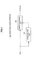
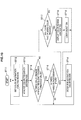
- FIG. 1 shows a configuration example of an image processing apparatus 100 according to a first embodiment of the disclosure.
- the image processing apparatus 100 includes an image analysis unit 101 and an image processing unit 102.
- the image analysis unit 101 constitutes an extraction color region determination unit.
- the image analysis unit 101 performs a process of determining an extraction color region including at least a partial region in an image using color information of an input image signal SVin.
- the input image signal SVin is a color image signal, and consists of, for example, a luminance signal Y, a red chrominance signal Cr and a blue chrominance signal Cb.
- the input image signal SVin is, for example, a captured image signal obtained by an imaging unit, a replay image signal, which is obtained by recording the captured image signal in a recording medium first and then replaying the captured image signal from the recording medium, or the like.
- the image analysis unit 101 When it is impossible to determine an extraction color region in a first image region, the image analysis unit 101 performs a process of determining an extraction color region in a second image region that is smaller than the first image region. In this case, the image analysis unit 101 performs a process of assigning every pixel or every block including a predetermined number of pixels in the first image region to any one of a plurality of color regions. Thereafter, when there are color regions of which frequencies exceed a threshold value, the image analysis unit 101 determines at least one color region among the color regions as an extraction color region.
- the image analysis unit 101 when there is no region of which a frequency exceeds the threshold value, the image analysis unit 101 performs the process of determining an extraction color region in the second image region that is smaller than the first image region. In other words, the image analysis unit 101 performs a process of assigning every pixel or every block including a predetermined number of pixels in the second image region to any one of the plurality of color regions. Thereafter, when there are color regions of which frequencies exceed the threshold value, the image analysis unit 101 determines at least one color region among the color regions as an extraction color region.
- the image analysis unit 101 repeats the process of determining an extraction color region, by replacing a second image region with the first image region and replacing a region, which is smaller than a first image region, with the second image region, when there is no region of which a frequency exceeds a threshold value.
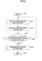
- the flowchart of FIG. 2 shows a processing sequence of the image analysis unit 101.
- the image analysis unit 101 performs a process on every frame or every predetermined number of frames according to the flowchart.
- the image analysis unit 101 starts processing in a step ST1, and then proceeds to a process of a step ST2.
- the image analysis unit 101 sets a color information analysis region.
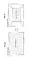
- FIG. 3 shows an example of a method of downsizing a color information analysis region.
- FIG. 3 (a) shows an initial state in which an entire screen is set as a color information analysis region.
- the color information analysis region is downsized toward a screen center as shown in FIG. 3 (b) .
- FIG. 4 shows another example of a method of downsizing a color information analysis region.
- FIG. 4 (a) shows an initial state in which an entire screen is set as a color information analysis region.
- the color information analysis region is downsized toward a focus point on the screen as shown in FIG. 4 (b) .
- the image analysis unit 101 acquires information on the focus point and the input image signal SVin from the imaging unit or a replay unit.
- an imaging unit in a digital still camera imaging apparatus
- the digital still camera can be focused on a subject present at a predetermined position on a screen by, for example, a phase-difference autofocus method or the like.
- the image analysis unit 101 acquires information on the detection position of the specific object and the input image signal SVin.
- the image analysis unit 101 performs color frequency distribution analysis in a step ST3.
- the image analysis unit 101 performs a process of assigning every pixel or every block including a predetermined number of pixels, for example, 8x8 pixels, to any one of the plurality of color regions.
- the image analysis unit 101 performs the assignment process.
- the color information may be hue information, saturation information, hue and saturation information, hue-equivalent information, and the like.
- the red chrominance signal Cr and the blue chrominance signal Cb are used as the hue information.
- B/G and R/G are used as the hue-equivalent information.
- B denotes a blue signal
- R denotes a red signal
- G denotes a green signal.
- hues are classified into a predetermined number of color regions.
- FIG. 5 shows a classification example classified into seven color regions, that is, color regions A to G.
- this example is obtained by cutting off a color wheel along the color region A and spreading the color wheel.
- the image analysis unit 101 determines to which one of the color regions A to G each pixel or each block belongs using the red chrominance signal Cr and the blue chrominance signal Cb, and performs assignment.
- the red chrominance signal Cr and the blue chrominance signal Cb of a block are determined to be averages, medians, or the like of the red chrominance signals Cr and the blue chrominance signals Cb of the predetermined number of pixels included in the block, respectively.
- FIG. 6 to FIG. 8 show examples of assignment process results, respectively. These examples show frequencies of respective color regions as screen occupation ratios.
- a ⁇ screen ⁇ denotes the ⁇ color information analysis region ⁇ set in the step ST2.
- all frequencies of the color regions A to G are less than the threshold value.
- the frequency of the color region E exceeds the threshold value, and the frequencies of the other color regions are less than the threshold value.
- the frequencies of the color regions B, D and F exceed the threshold value, and the frequencies of the other color regions are less than the threshold value.
- the threshold value is set to, for example, about 30% to 40% of the area of the entire screen, but is not limited thereto.
- the image analysis unit 101 determines in a step ST4 whether or not there is a color region of which a frequency exceeds the threshold value.
- the image analysis unit 101 proceeds back to the step ST2 to change the color information analysis region.
- a color information analysis region after the change (a second image region) is downsized in comparison with the color information analysis region before the change (a first image region) (see FIG. 3 and FIG. 4 ).
- the image analysis unit 101 proceeds to a process of a step ST5.
- the image analysis unit 101 determines at least one color region among the color regions of which the frequencies exceed the threshold value as an extraction color region, and outputs information on the extraction color region.
- the image analysis unit 101 determines the color region as an extraction color region. Also, in this case, when there are a plurality of color regions of which frequencies exceed the threshold value (see FIG. 8 ), the image analysis unit 101 determines, for example, one color region or a predetermined number of color regions in decreasing frequency order among the plurality of color regions as extraction color regions.
- the image analysis unit 101 finishes processing in a step ST6.
- the image processing unit 102 performs image processing on the input image signal SVin on the basis of the extraction color region determined by the image analysis unit 101, and thereby obtains an output image signal SVout.
- the image processing unit 102 performs image processing on the extraction color region of the input image signal SVin and/or the remaining region of the input image signal SVin excluding the extraction color region.
- the image processing unit 102 performs image processing on at least one region between the extraction region of the input image signal SVin and the remaining region of the input image signal SVin excluding the extraction region.
- the image processing unit 102 performs, for example, a process of emphasizing saturation on the extraction color region of the input image signal SVin. Also, the image processing unit 102 performs, for example, achromatic coloring, that is, a process of dropping saturation to zero, on the remaining region of the input image signal SVin excluding the extraction color region.
- the input image signal SVin for example, a captured image signal or a replay image signal
- the image analysis unit 101 determines an extraction color region including at least a partial region in an image using color information of the input image signal SVin, and supplies information on the region to the image processing unit 102.
- the image processing unit 102 performs image processing on the input image signal SVin on the basis of the extraction color region determined by the image analysis unit 101, thereby obtaining the output image signal SVout.
- the image processing unit 102 performs image processing on the extraction color region of the input image signal SVin and/or the remaining region of the input image signal SVin excluding the extraction color region. For example, a process of achromatic coloring is performed on the remaining region of the input image signal SVin excluding the extraction color region, implementing the so-called partial color effect.
- the image analysis unit 101 automatically determines at least one extraction color region using color information of the input image signal SVin. For this reason, the image processing unit 102 can reliably perform image processing on the input image signal SVin on the basis of information on the extraction color region. For example, the process of achromatic coloring is performed on the remaining region of the input image signal SVin excluding the extraction color region, so that the so-called partial color effect can be reliably implemented.
- the image analysis unit 101 in the image processing apparatus 100 shown in FIG. 1 changes a color information analysis region with a downsized region and performs the process of determining an extraction color region again. For this reason, it is possible to automatically determine at least one extraction color region.
- General digital still cameras include a camera that has a focus point for implementing autofocus, and a camera of which a focus position can be freely set by a user.
- a camera that has a focus point for implementing autofocus
- a camera of which a focus position can be freely set by a user since an object desired to be in focus becomes a main subject, there is a high possibility that the object includes many color regions desired to be extracted. For this reason, by downsizing a color information analysis region toward a focus point, it is possible to determine a color region more preferred by a user as an extraction color region.
- the input image signal SVin consists of the luminance signal Y, the red chrominance signal Cr and the blue chrominance signal Cb, but may consist of three primary color signals, that is, the red signal R, the green signal G and the blue signal B.
- the image analysis unit 101 and the image processing unit 102 may perform processing using the red signal R, the green signal G and the blue signal B, or perform processing after appropriately converting the red signal R, the green signal G and the blue signal B into the luminance signal Y, the red chrominance signal Cr and the blue chrominance signal Cb.
- FIG. 9 shows a configuration example of a digital still camera (imaging apparatus) 100A according to a second embodiment of the disclosure.
- the digital still camera 100A includes a camera body unit 110, a CPU 111, a memory 112, a user manipulation unit 113 and a display unit 114, and the respective units are connected with each other by an internal bus 115.
- the CPU 111 controls operation of the respective units of the digital still camera 100A.
- the memory 112 consists of a flash ROM, a DRAM, and the like.
- the flash ROM performs storage of control software and data.
- the DRAM constitutes a work area of the CPU 111.
- the CPU 111 loads software or data read out from the flash ROM into the DRAM and runs the software, thereby controlling the respective units of the digital still camera 100A.
- the user manipulation unit 113 and the display unit 114 constitute a user interface.
- the user manipulation unit 113 consists of a key, a button or a dial placed on a case of the digital still camera 100A that is not shown in the drawing, touch panels placed on a display surface of the display unit 114, or the like.
- the display unit 114 consists of a display panel such as a Liquid Crystal Display (LCD).
- LCD Liquid Crystal Display
- the camera body unit 110 includes an imaging unit 103, an image analysis unit 101A, an image processing unit 102 and an output unit 104.
- the imaging unit 103 photographs a subject to obtain a captured image signal SVa, and outputs the captured image signal SVa.
- the captured image signal SVa is a color image signal, and consists of, for example, a luminance signal Y, a red chrominance signal Cr and a blue chrominance signal Cb.
- the imaging unit 103 has an autofocus function, such as the phase-different autofocus method, and can focus on a subject present at a predetermined position on a screen. Also, the imaging unit 103 has a function of detecting a specific object such as a face. The imaging unit 103 outputs not only the aforementioned captured image signal SVa but also additional information ladd including information on a focus point, information on a detection position of a specific object, and the like.
- the image analysis unit 101A performs a process of determining an extraction color region including at least a partial region in an image using color information of the captured image signal SVa.
- the image analysis unit 101A performs a process of determining an extraction color region in a second image region that is smaller than the first image region.
- the image analysis unit 101A performs a process of assigning every pixel or every block including a predetermined number of pixels in the first image region to any one of a plurality of color regions. Thereafter, when there are color regions of which frequencies exceed a threshold value, the image analysis unit 101A determines at least one color region among the color regions as an extraction color region. On the other hand, when there is no region of which a frequency exceeds the threshold value, the image analysis unit 101A performs the process of determining an extraction color region in the second image region that is smaller than the first image region.
- the image analysis unit 101A updates the determined extraction color region.
- the change in photography state denotes a change in photography state occurring when a user clearly performs change of an exposure mode, zoom handling, and the like using the user manipulation unit 113. In this way, it is possible to prevent the extraction color region from gradually varying due to minute difference in view angle or motion of the subject that the user does not intend.
- the flowchart of FIG. 10 shows a processing sequence of the image analysis unit 101A.
- the image analysis unit 101A starts processing in a step ST11 on the basis of, for example, initiation manipulation of the user using the user manipulation unit 113, and then proceeds to a process of a step ST12.
- the image analysis unit 101A sets a color information analysis region, like the process performed by the image analysis unit 101 of the image processing apparatus 100 of FIG. 1 in the step ST2 of FIG. 2 .
- the image analysis unit 101A sets an entire screen as the color information analysis region, and then gradually downsizes the region every time there is no color region of which a frequency exceeds the threshold value and the process proceeds back to the step ST12.
- the color information analysis region before the change constitutes a first image region and a color information analysis region after the change constitutes a second image region.
- the color information analysis region is downsized toward a screen center (see FIG. 3 ).
- the color information analysis region is downsized toward a focus point on the screen on the basis of, for example, the information on the focus point included as the additional information from the imaging unit 103 (see FIG. 4 ). Further, in this case, the color information analysis region is downsized toward the detection position of the specific object on the screen on the basis of, for example, the information on the detection position of the specific object included in the additional information from the imaging unit 103.
- the image analysis unit 101A performs color frequency distribution analysis in a step ST13, like the process performed by the image analysis unit 101 of the image processing apparatus 100 of FIG. 1 in the step ST3 of FIG. 2 .
- the image analysis unit 101A performs a process of assigning every pixel or every block including a predetermined number of pixels, for example, 8x8 pixels, to any one of the plurality of color regions.
- the image analysis unit 101A performs the assignment process.
- the image analysis unit 101A determines whether or not there is a color region of which a frequency exceeds the threshold value. When it is determined that there is no color region of which a frequency exceeds the threshold value (see FIG. 6 ), the image analysis unit 101A proceeds back to the step ST12 to change the color information analysis region. In this case, a color information analysis region after the change (a second image region) is downsized in comparison with the color information analysis region before the change (a first image region) (see FIG. 3 and FIG. 4 ).
- the image analysis unit 101A determines in a step ST15 whether or not there is a change in photography state. When it is determined that there is no change, the image analysis unit 101A proceeds back to the step ST12 to set the color information analysis region to the initial state, that is, the entire screen, and repeats the same process as described above.
- the image analysis unit 101A proceeds to a process of a step ST16. Also, when it is determined in the step ST14 that there is a color region of which a frequency exceeds the threshold value for the first time after the process is started in the step S11, the image analysis unit 101A directly proceeds to the process of the step ST16.
- the image analysis unit 101A determines at least one color region among color regions of which frequencies exceed the threshold value as an extraction color region, and outputs information on the extraction color region on the screen.
- This process is the same as the process performed by the image analysis unit 101 of the image processing apparatus 100 of FIG. 1 in the step ST5 of FIG. 2 .
- the image analysis unit 101A proceeds to the process of the step ST16 only when it is determined that there is a change in photography state other than the first time after the process is started in the step S11. In this way, the determined extraction color region is updated when there is a change in photography state.
- the image analysis unit 101A proceeds back to the step ST12 to set the color information analysis region to the initial state, that is, the entire screen, and repeats the same process as described above.
- the image processing unit 102 performs image processing on the captured image signal SVa on the basis of the extraction color region determined by the image analysis unit 101A, and thereby obtains a processed image signal SVb.
- the image processing unit 102 performs image processing on the extraction color region of the captured image signal SVa and/or the remaining region of the captured image signal SVa excluding the extraction color region.
- the image processing unit 102 performs, for example, a process of emphasizing saturation on the extraction color region of the captured image signal SVa.
- the image processing unit 102 performs, for example, achromatic coloring, that is, the process of dropping saturation to zero, on the remaining region of the captured image signal SVa excluding the extraction color region.
- the output unit 104 performs a process of outputting the processed image signal SVb output from the image processing unit 102 to the outside.
- the output unit 104 records the processed image signal SVb as a JPEG image file in a recording medium, such as a memory card.
- the captured image signal SVa which is obtained by photographing a subject using the imaging unit 103, is supplied to the image analysis unit 101A and the image processing unit 102. Also, additional information ladd, which is output from the imaging unit 103 and includes information on a focus point, information on a detection position of a specific object, and the like, is supplied to the image analysis unit 101A.
- the image analysis unit 101A determines an extraction color region including at least a partial region in an image using color information of the captured image signal SVa, and supplies information on the region to the image processing unit 102.
- the image processing unit 102 performs image processing on the captured image signal SVa on the basis of the extraction color region determined by the image analysis unit 101A, thereby obtaining the processed image signal SVb.
- the image processing unit 102 performs image processing on the extraction color region of the captured image signal SVa and/or the remaining region of the captured image signal SVa excluding the extraction color region. For example, a process of achromatic coloring is performed on the remaining region of the captured image signal SVa excluding the extraction color region, and thereby the so-called partial color effect is implemented.
- the processed image signal SVb obtained by the image processing unit 102 is supplied to the output unit 104.
- the output unit 104 performs the process of outputting the processed image signal SVb to the outside.
- the output unit 104 records the processed image signal SVb as a JPEG image file in a recording medium, such as a memory card.
- the image analysis unit 101A of the camera body unit 110 automatically determines at least one extraction color region using color information of the captured image signal SVa. For this reason, the image processing unit 102 of the camera body unit 110 can reliably perform image processing on the captured image signal SVa on the basis of information on the extraction color region. For example, the process of achromatic coloring is performed on the remaining region of the captured image signal SVa excluding the extraction color region, so that the so-called partial color effect can be reliably implemented.
- the image analysis unit 101A of the camera body unit 110 in the digital still camera 100A shown in FIG. 9 changes a color information analysis region with a downsized region and performs the process of determining an extraction color region again. For this reason, it is possible to automatically determine at least one extraction color region. At this time, if the color information analysis region is downsized toward a focus point, it is possible to determine a color region more preferred by a user as an extraction color region.
- the image analysis unit 101A of the camera body unit 110 in the digital still camera 100A shown in FIG. 9 updates the determined extraction color region. For this reason, the extraction color region determined by the image analysis unit 101A does not vary unless a user clearly performs change of an exposure mode, zoom handling, and the like using the user manipulation unit 113. Thus, it is possible to prevent the extraction color region from gradually varying due to a minute difference in view angle or motion of a subject that the user does not intend.
- the process of the step ST12 to the step ST14 is repeatedly performed even when there is no change in photography state.
- the processing sequence may be set to perform the process of these steps ST12 to ST14 and determine an extraction color region only when there is a change in photography state.
- the image analysis units 101 and 101A determine, for example, one color region or a predetermined number of color regions in decreasing frequency order among the plurality of color regions as extraction color regions.
- a color region to be determined as an extraction color region may be configured to be selected by a user. An operation example of the image analysis unit 101A and the like in this case will be described.
- the CPU 111 determines in a step ST17 whether or not there are two or more color regions of which frequencies exceed the threshold value.
- the image analysis unit 101A directly proceeds to the process of the step ST16 and determines the color region as an extraction color region.
- the CPU 111 displays N color regions (N is an integer equal to or greater than 2) in decreasing frequency order among the color regions as candidate color regions on the display unit 114 in a step ST18. In this way, a user is prompted to select the extraction color region.
- FIG. 11 shows a displayed example of candidate color regions in the display unit 114 of the digital still camera 100A. In this example, three candidate color regions are displayed by rectangles painted in the colors.
- a step ST19 the user manipulates the user manipulation unit 113 on the basis of the display of the display unit 114 to select a color region to be determined as an extraction color region.
- the example of FIG. 11 shows a state in which one color region on the left is selected and surrounded by a boundary FL.
- the image analysis unit 101 A determines the predetermined number of color regions selected by the user as extraction color regions in the step ST16.
- candidate color regions are displayed on the display unit 114 of the digital still camera 100A, and a user manipulates the user manipulation unit 113 of the digital still camera 100A to select a color region to be determined as an extraction color region.
- a display unit that displays the candidate color regions may be an external device.
- a manipulation unit with which the user performs the selection manipulation may be an external device such as a remote controller or a device over a network.
- the digital still camera 100A which is an image processing apparatus, may have a user selection acquisition unit's function of causing a display unit to display N regions (N is an integer equal to or greater than 2) in decreasing frequency order among a plurality of color regions of which frequencies exceed a threshold value as candidate color regions, and prompting a user to select an extraction region on the basis of the display of the display unit.
- a color information analysis region is gradually downsized toward a screen center or a focus point on a screen.
- this process is merely an option, and may not be performed. In this case, for example, one color region or a predetermined number of color regions in decreasing frequency order are simply determined as extraction color regions without using a threshold value.
- processing of the image analysis units 101 and 101Aand the image processing unit 102 can be performed by software as well as hardware.
- a program in which a processing sequence is recorded is installed in a memory in a computer implemented in dedicated hardware and executed.
- the program can be installed in a general purpose computer capable of performing various kinds of processing and executed.
- the present technology can have a configuration as follows.
Landscapes
- Engineering & Computer Science (AREA)
- Multimedia (AREA)
- Signal Processing (AREA)
- Theoretical Computer Science (AREA)
- Physics & Mathematics (AREA)
- General Physics & Mathematics (AREA)
- Computer Vision & Pattern Recognition (AREA)
- Studio Devices (AREA)
- Image Processing (AREA)
- Image Analysis (AREA)
- Processing Or Creating Images (AREA)
- Color Television Image Signal Generators (AREA)
- Facsimile Image Signal Circuits (AREA)
Priority Applications (1)
| Application Number | Priority Date | Filing Date | Title |
|---|---|---|---|
| EP18162295.2A EP3361717B1 (de) | 2011-05-18 | 2012-03-26 | Bildverarbeitungsvorrichtung, bildverarbeitungsverfahren, programm und bildgebungsvorrichtung |
Applications Claiming Priority (1)
| Application Number | Priority Date | Filing Date | Title |
|---|---|---|---|
| JP2011111350A JP6279825B2 (ja) | 2011-05-18 | 2011-05-18 | 画像処理装置、画像処理方法、プログラムおよび撮像装置 |
Related Child Applications (2)
| Application Number | Title | Priority Date | Filing Date |
|---|---|---|---|
| EP18162295.2A Division-Into EP3361717B1 (de) | 2011-05-18 | 2012-03-26 | Bildverarbeitungsvorrichtung, bildverarbeitungsverfahren, programm und bildgebungsvorrichtung |
| EP18162295.2A Division EP3361717B1 (de) | 2011-05-18 | 2012-03-26 | Bildverarbeitungsvorrichtung, bildverarbeitungsverfahren, programm und bildgebungsvorrichtung |
Publications (3)
| Publication Number | Publication Date |
|---|---|
| EP2525562A2 true EP2525562A2 (de) | 2012-11-21 |
| EP2525562A3 EP2525562A3 (de) | 2014-04-09 |
| EP2525562B1 EP2525562B1 (de) | 2018-07-04 |
Family
ID=46062027
Family Applications (2)
| Application Number | Title | Priority Date | Filing Date |
|---|---|---|---|
| EP12161337.6A Not-in-force EP2525562B1 (de) | 2011-05-18 | 2012-03-26 | Bildverarbeitungsvorrichtung, Bildverarbeitungsverfahren, Programm und Bildgebungsvorrichtung |
| EP18162295.2A Not-in-force EP3361717B1 (de) | 2011-05-18 | 2012-03-26 | Bildverarbeitungsvorrichtung, bildverarbeitungsverfahren, programm und bildgebungsvorrichtung |
Family Applications After (1)
| Application Number | Title | Priority Date | Filing Date |
|---|---|---|---|
| EP18162295.2A Not-in-force EP3361717B1 (de) | 2011-05-18 | 2012-03-26 | Bildverarbeitungsvorrichtung, bildverarbeitungsverfahren, programm und bildgebungsvorrichtung |
Country Status (6)
| Country | Link |
|---|---|
| US (3) | US8948505B2 (de) |
| EP (2) | EP2525562B1 (de) |
| JP (1) | JP6279825B2 (de) |
| KR (1) | KR102048581B1 (de) |
| CN (2) | CN102790886B (de) |
| TW (1) | TW201312991A (de) |
Cited By (2)
| Publication number | Priority date | Publication date | Assignee | Title |
|---|---|---|---|---|
| EP2790396A1 (de) * | 2013-04-08 | 2014-10-15 | Samsung Electronics Co., Ltd. | Farbextraktionsbasiertes Bildverarbeitungsverfahren, computerlesbares Speichermedium damit und Digitalbildvorrichtung |
| US11330177B2 (en) | 2018-01-25 | 2022-05-10 | Sony Semiconductor Solutions Corporation | Image processing apparatus and image processing method |
Families Citing this family (17)
| Publication number | Priority date | Publication date | Assignee | Title |
|---|---|---|---|---|
| JP5499779B2 (ja) * | 2010-03-03 | 2014-05-21 | ソニー株式会社 | 色むら検査装置および色むら検査方法 |
| WO2011158336A1 (ja) * | 2010-06-15 | 2011-12-22 | 株式会社ナビタイムジャパン | ナビゲーションシステム、端末装置、ナビゲーションサーバ、ナビゲーション装置、ナビゲーション方法、および、プログラム |
| JP6279825B2 (ja) | 2011-05-18 | 2018-02-14 | ソニー株式会社 | 画像処理装置、画像処理方法、プログラムおよび撮像装置 |
| JP2014207659A (ja) | 2013-03-19 | 2014-10-30 | パナソニック株式会社 | 画像処理装置及び画像処理方法及び撮像装置 |
| JP2014207658A (ja) | 2013-03-19 | 2014-10-30 | パナソニック株式会社 | 画像処理装置及び撮像装置及び画像処理方法 |
| JP6355327B2 (ja) * | 2013-12-18 | 2018-07-11 | キヤノン株式会社 | 画像処理装置及び方法 |
| US11030778B2 (en) * | 2014-03-31 | 2021-06-08 | Healthy.Io Ltd. | Methods and apparatus for enhancing color vision and quantifying color interpretation |
| JP5818050B1 (ja) * | 2015-01-28 | 2015-11-18 | ビックリック株式会社 | ステータス判定システム |
| CN105516606A (zh) * | 2016-01-21 | 2016-04-20 | 努比亚技术有限公司 | 拍照装置及方法 |
| WO2018105181A1 (ja) * | 2016-12-07 | 2018-06-14 | 住友電気工業株式会社 | 画像処理プログラム、色ラベル、検知装置、画像処理装置、画像処理方法および画像処理システム |
| CN108197567B (zh) * | 2017-12-29 | 2021-08-24 | 百度在线网络技术(北京)有限公司 | 用于图像处理的方法、装置和计算机可读介质 |
| US11417023B2 (en) * | 2018-10-04 | 2022-08-16 | Sony Corporation | Image processing device, image processing method, and program |
| JP7349653B2 (ja) * | 2018-12-10 | 2023-09-25 | 株式会社サンライン | 画像識別システム |
| GB201904072D0 (en) * | 2019-03-25 | 2019-05-08 | Secr Defence | Dazzle resilient video camera or video camera module |
| CN110766606B (zh) * | 2019-10-29 | 2023-09-26 | 维沃移动通信有限公司 | 一种图像处理方法及电子设备 |
| US11488285B2 (en) | 2020-04-13 | 2022-11-01 | Apple Inc. | Content based image processing |
| US11847814B2 (en) * | 2020-09-14 | 2023-12-19 | Dragonfruit Ai, Inc. | Video data search using color wheel associations |
Citations (1)
| Publication number | Priority date | Publication date | Assignee | Title |
|---|---|---|---|---|
| JPH0698232A (ja) | 1992-09-10 | 1994-04-08 | Canon Inc | 画像認識装置及び撮像装置 |
Family Cites Families (22)
| Publication number | Priority date | Publication date | Assignee | Title |
|---|---|---|---|---|
| JPH05274372A (ja) | 1992-03-25 | 1993-10-22 | Mitsubishi Electric Corp | 画像の特徴色自動付加装置 |
| JP2000232609A (ja) * | 1999-02-10 | 2000-08-22 | Matsushita Electric Ind Co Ltd | 特殊効果処理方法及び画像処理装置 |
| JP3825740B2 (ja) * | 2001-12-07 | 2006-09-27 | 株式会社リコー | 画像処理装置、画像処理方法、およびコンピュータが実行するためのプログラム |
| JP4684595B2 (ja) * | 2004-08-05 | 2011-05-18 | ソニー株式会社 | 画像表示装置 |
| JP4533168B2 (ja) * | 2005-01-31 | 2010-09-01 | キヤノン株式会社 | 撮像装置及びその制御方法 |
| JP4498224B2 (ja) * | 2005-06-14 | 2010-07-07 | キヤノン株式会社 | 画像処理装置およびその方法 |
| JP2007028548A (ja) * | 2005-07-21 | 2007-02-01 | Fujifilm Holdings Corp | 画像編集装置、及び画像編集プログラム |
| JP2007043506A (ja) * | 2005-08-03 | 2007-02-15 | Canon Inc | 画像処理装置及びその画像処理方法、プログラム並びに記憶媒体 |
| JP5086563B2 (ja) * | 2006-05-26 | 2012-11-28 | オリンパス株式会社 | 画像処理装置及び画像処理プログラム |
| JP4883783B2 (ja) * | 2006-12-22 | 2012-02-22 | キヤノン株式会社 | 画像処理装置およびその方法 |
| CN100493134C (zh) * | 2007-03-09 | 2009-05-27 | 北京中星微电子有限公司 | 一种图像处理的方法和系统 |
| JP5211768B2 (ja) * | 2007-03-16 | 2013-06-12 | 株式会社ニコン | 画像処理装置、撮像装置、および画像処理プログラム |
| US8055071B2 (en) * | 2007-03-16 | 2011-11-08 | Nikon Corporation | Image processing apparatus, imaging apparatus and recording medium storing image processing program |
| JP4895878B2 (ja) * | 2007-03-19 | 2012-03-14 | 富士フイルム株式会社 | 代表色抽出方法、および代表色抽出装置 |
| JP2008236204A (ja) * | 2007-03-19 | 2008-10-02 | Kyocera Mita Corp | 画像処理装置 |
| JP4898532B2 (ja) * | 2007-04-13 | 2012-03-14 | 富士フイルム株式会社 | 画像処理装置および撮影システム並びに瞬き状態検出方法、瞬き状態検出プログラムおよびそのプログラムが記録された記録媒体 |
| JP2009033361A (ja) * | 2007-07-25 | 2009-02-12 | Fuji Xerox Co Ltd | 色調整装置、画像形成装置およびプログラム |
| JP2009175281A (ja) * | 2008-01-22 | 2009-08-06 | Canon Inc | 画像形成装置および画像処理方法 |
| CN101287134B (zh) * | 2008-05-28 | 2011-01-26 | 四川虹微技术有限公司 | 自适应肤色补偿方法 |
| KR101329770B1 (ko) * | 2008-08-08 | 2013-11-15 | 삼성전자주식회사 | 이미지 보정 방법과 이를 위한 화상형성장치 그리고 이미지의 번짐 현상 보정 방법 |
| JP5499779B2 (ja) | 2010-03-03 | 2014-05-21 | ソニー株式会社 | 色むら検査装置および色むら検査方法 |
| JP6279825B2 (ja) | 2011-05-18 | 2018-02-14 | ソニー株式会社 | 画像処理装置、画像処理方法、プログラムおよび撮像装置 |
-
2011
- 2011-05-18 JP JP2011111350A patent/JP6279825B2/ja not_active Expired - Fee Related
-
2012
- 2012-03-26 EP EP12161337.6A patent/EP2525562B1/de not_active Not-in-force
- 2012-03-26 EP EP18162295.2A patent/EP3361717B1/de not_active Not-in-force
- 2012-03-27 TW TW101110583A patent/TW201312991A/zh unknown
- 2012-04-27 US US13/457,691 patent/US8948505B2/en active Active
- 2012-05-09 KR KR1020120049091A patent/KR102048581B1/ko not_active Expired - Fee Related
- 2012-05-11 CN CN201210153782.3A patent/CN102790886B/zh active Active
- 2012-05-11 CN CN201810061234.5A patent/CN108111827B/zh active Active
-
2014
- 2014-12-22 US US14/579,175 patent/US9600902B2/en not_active Expired - Fee Related
-
2017
- 2017-02-01 US US15/422,142 patent/US9916518B2/en active Active
Patent Citations (1)
| Publication number | Priority date | Publication date | Assignee | Title |
|---|---|---|---|---|
| JPH0698232A (ja) | 1992-09-10 | 1994-04-08 | Canon Inc | 画像認識装置及び撮像装置 |
Cited By (2)
| Publication number | Priority date | Publication date | Assignee | Title |
|---|---|---|---|---|
| EP2790396A1 (de) * | 2013-04-08 | 2014-10-15 | Samsung Electronics Co., Ltd. | Farbextraktionsbasiertes Bildverarbeitungsverfahren, computerlesbares Speichermedium damit und Digitalbildvorrichtung |
| US11330177B2 (en) | 2018-01-25 | 2022-05-10 | Sony Semiconductor Solutions Corporation | Image processing apparatus and image processing method |
Also Published As
| Publication number | Publication date |
|---|---|
| EP2525562B1 (de) | 2018-07-04 |
| JP2012244337A (ja) | 2012-12-10 |
| US9600902B2 (en) | 2017-03-21 |
| CN108111827B (zh) | 2021-04-02 |
| TW201312991A (zh) | 2013-03-16 |
| US20120294522A1 (en) | 2012-11-22 |
| US20150103201A1 (en) | 2015-04-16 |
| EP3361717B1 (de) | 2020-07-29 |
| KR20120129768A (ko) | 2012-11-28 |
| CN108111827A (zh) | 2018-06-01 |
| KR102048581B1 (ko) | 2019-11-25 |
| JP6279825B2 (ja) | 2018-02-14 |
| EP2525562A3 (de) | 2014-04-09 |
| US9916518B2 (en) | 2018-03-13 |
| CN102790886B (zh) | 2018-05-22 |
| EP3361717A1 (de) | 2018-08-15 |
| US8948505B2 (en) | 2015-02-03 |
| CN102790886A (zh) | 2012-11-21 |
| US20170147897A1 (en) | 2017-05-25 |
Similar Documents
| Publication | Publication Date | Title |
|---|---|---|
| EP3361717B1 (de) | Bildverarbeitungsvorrichtung, bildverarbeitungsverfahren, programm und bildgebungsvorrichtung | |
| US10102787B2 (en) | Image signal processing apparatus and control method therefor | |
| US9451169B2 (en) | Imaging apparatus and capture assist mark usage control method | |
| US20070266312A1 (en) | Method for displaying face detection frame, method for displaying character information, and image-taking device | |
| JP2005275977A (ja) | 画像表示方法、画像表示装置及び画像表示プログラム | |
| US11194993B2 (en) | Display apparatus and display control method for displaying images | |
| JP2004040559A (ja) | 画像処理方法、画像処理装置、及び画像処理プログラム | |
| JP2012044243A (ja) | 画像処理装置、撮像装置及び画像処理プログラム | |
| US8502882B2 (en) | Image pick-up apparatus, white balance setting method and recording medium | |
| JP4475041B2 (ja) | 電子カメラ装置、及び色調整方法 | |
| JP2003348335A (ja) | 画像処理方法、画像処理装置、及び画像処理プログラム | |
| JP7652749B2 (ja) | 画像処理装置、画像処理方法、および撮像装置 | |
| JP6566004B2 (ja) | 画像処理装置、画像処理方法、プログラムおよび撮像装置 | |
| JP2010022068A (ja) | 電子カメラ装置、色調整方法及びプログラム | |
| JP2009217343A (ja) | 画像処理プログラム、画像処理方法および電子カメラ | |
| JP6350965B2 (ja) | 画像処理装置、画像処理方法、画像処理プログラム、画像のデータ構造及びコンピュータ読み取り可能な記録媒体 | |
| JP2018088618A (ja) | 撮像装置 | |
| JP2006270631A (ja) | デジタルカメラ | |
| JP2011182187A (ja) | 撮像装置及びその制御方法 | |
| JP2008035457A (ja) | 電子カメラおよび画像処理プログラム |
Legal Events
| Date | Code | Title | Description |
|---|---|---|---|
| PUAI | Public reference made under article 153(3) epc to a published international application that has entered the european phase |
Free format text: ORIGINAL CODE: 0009012 |
|
| 17P | Request for examination filed |
Effective date: 20120329 |
|
| AK | Designated contracting states |
Kind code of ref document: A2 Designated state(s): AL AT BE BG CH CY CZ DE DK EE ES FI FR GB GR HR HU IE IS IT LI LT LU LV MC MK MT NL NO PL PT RO RS SE SI SK SM TR |
|
| AX | Request for extension of the european patent |
Extension state: BA ME |
|
| PUAL | Search report despatched |
Free format text: ORIGINAL CODE: 0009013 |
|
| AK | Designated contracting states |
Kind code of ref document: A3 Designated state(s): AL AT BE BG CH CY CZ DE DK EE ES FI FR GB GR HR HU IE IS IT LI LT LU LV MC MK MT NL NO PL PT RO RS SE SI SK SM TR |
|
| AX | Request for extension of the european patent |
Extension state: BA ME |
|
| RIC1 | Information provided on ipc code assigned before grant |
Ipc: H04N 1/62 20060101AFI20140304BHEP |
|
| 17Q | First examination report despatched |
Effective date: 20160405 |
|
| GRAP | Despatch of communication of intention to grant a patent |
Free format text: ORIGINAL CODE: EPIDOSNIGR1 |
|
| STAA | Information on the status of an ep patent application or granted ep patent |
Free format text: STATUS: GRANT OF PATENT IS INTENDED |
|
| INTG | Intention to grant announced |
Effective date: 20180124 |
|
| GRAS | Grant fee paid |
Free format text: ORIGINAL CODE: EPIDOSNIGR3 |
|
| GRAA | (expected) grant |
Free format text: ORIGINAL CODE: 0009210 |
|
| STAA | Information on the status of an ep patent application or granted ep patent |
Free format text: STATUS: THE PATENT HAS BEEN GRANTED |
|
| AK | Designated contracting states |
Kind code of ref document: B1 Designated state(s): AL AT BE BG CH CY CZ DE DK EE ES FI FR GB GR HR HU IE IS IT LI LT LU LV MC MK MT NL NO PL PT RO RS SE SI SK SM TR |
|
| REG | Reference to a national code |
Ref country code: GB Ref legal event code: FG4D |
|
| REG | Reference to a national code |
Ref country code: CH Ref legal event code: EP |
|
| REG | Reference to a national code |
Ref country code: AT Ref legal event code: REF Ref document number: 1015742 Country of ref document: AT Kind code of ref document: T Effective date: 20180715 |
|
| REG | Reference to a national code |
Ref country code: IE Ref legal event code: FG4D |
|
| REG | Reference to a national code |
Ref country code: DE Ref legal event code: R096 Ref document number: 602012047989 Country of ref document: DE |
|
| REG | Reference to a national code |
Ref country code: NL Ref legal event code: FP |
|
| REG | Reference to a national code |
Ref country code: LT Ref legal event code: MG4D |
|
| REG | Reference to a national code |
Ref country code: AT Ref legal event code: MK05 Ref document number: 1015742 Country of ref document: AT Kind code of ref document: T Effective date: 20180704 |
|
| PG25 | Lapsed in a contracting state [announced via postgrant information from national office to epo] |
Ref country code: CZ Free format text: LAPSE BECAUSE OF FAILURE TO SUBMIT A TRANSLATION OF THE DESCRIPTION OR TO PAY THE FEE WITHIN THE PRESCRIBED TIME-LIMIT Effective date: 20180704 Ref country code: NO Free format text: LAPSE BECAUSE OF FAILURE TO SUBMIT A TRANSLATION OF THE DESCRIPTION OR TO PAY THE FEE WITHIN THE PRESCRIBED TIME-LIMIT Effective date: 20181004 Ref country code: GR Free format text: LAPSE BECAUSE OF FAILURE TO SUBMIT A TRANSLATION OF THE DESCRIPTION OR TO PAY THE FEE WITHIN THE PRESCRIBED TIME-LIMIT Effective date: 20181005 Ref country code: BG Free format text: LAPSE BECAUSE OF FAILURE TO SUBMIT A TRANSLATION OF THE DESCRIPTION OR TO PAY THE FEE WITHIN THE PRESCRIBED TIME-LIMIT Effective date: 20181004 Ref country code: AT Free format text: LAPSE BECAUSE OF FAILURE TO SUBMIT A TRANSLATION OF THE DESCRIPTION OR TO PAY THE FEE WITHIN THE PRESCRIBED TIME-LIMIT Effective date: 20180704 Ref country code: LT Free format text: LAPSE BECAUSE OF FAILURE TO SUBMIT A TRANSLATION OF THE DESCRIPTION OR TO PAY THE FEE WITHIN THE PRESCRIBED TIME-LIMIT Effective date: 20180704 Ref country code: PL Free format text: LAPSE BECAUSE OF FAILURE TO SUBMIT A TRANSLATION OF THE DESCRIPTION OR TO PAY THE FEE WITHIN THE PRESCRIBED TIME-LIMIT Effective date: 20180704 Ref country code: RS Free format text: LAPSE BECAUSE OF FAILURE TO SUBMIT A TRANSLATION OF THE DESCRIPTION OR TO PAY THE FEE WITHIN THE PRESCRIBED TIME-LIMIT Effective date: 20180704 Ref country code: IS Free format text: LAPSE BECAUSE OF FAILURE TO SUBMIT A TRANSLATION OF THE DESCRIPTION OR TO PAY THE FEE WITHIN THE PRESCRIBED TIME-LIMIT Effective date: 20181104 Ref country code: FI Free format text: LAPSE BECAUSE OF FAILURE TO SUBMIT A TRANSLATION OF THE DESCRIPTION OR TO PAY THE FEE WITHIN THE PRESCRIBED TIME-LIMIT Effective date: 20180704 Ref country code: SE Free format text: LAPSE BECAUSE OF FAILURE TO SUBMIT A TRANSLATION OF THE DESCRIPTION OR TO PAY THE FEE WITHIN THE PRESCRIBED TIME-LIMIT Effective date: 20180704 |
|
| PG25 | Lapsed in a contracting state [announced via postgrant information from national office to epo] |
Ref country code: AL Free format text: LAPSE BECAUSE OF FAILURE TO SUBMIT A TRANSLATION OF THE DESCRIPTION OR TO PAY THE FEE WITHIN THE PRESCRIBED TIME-LIMIT Effective date: 20180704 Ref country code: HR Free format text: LAPSE BECAUSE OF FAILURE TO SUBMIT A TRANSLATION OF THE DESCRIPTION OR TO PAY THE FEE WITHIN THE PRESCRIBED TIME-LIMIT Effective date: 20180704 Ref country code: LV Free format text: LAPSE BECAUSE OF FAILURE TO SUBMIT A TRANSLATION OF THE DESCRIPTION OR TO PAY THE FEE WITHIN THE PRESCRIBED TIME-LIMIT Effective date: 20180704 Ref country code: ES Free format text: LAPSE BECAUSE OF FAILURE TO SUBMIT A TRANSLATION OF THE DESCRIPTION OR TO PAY THE FEE WITHIN THE PRESCRIBED TIME-LIMIT Effective date: 20180704 |
|
| REG | Reference to a national code |
Ref country code: DE Ref legal event code: R097 Ref document number: 602012047989 Country of ref document: DE |
|
| PG25 | Lapsed in a contracting state [announced via postgrant information from national office to epo] |
Ref country code: RO Free format text: LAPSE BECAUSE OF FAILURE TO SUBMIT A TRANSLATION OF THE DESCRIPTION OR TO PAY THE FEE WITHIN THE PRESCRIBED TIME-LIMIT Effective date: 20180704 Ref country code: IT Free format text: LAPSE BECAUSE OF FAILURE TO SUBMIT A TRANSLATION OF THE DESCRIPTION OR TO PAY THE FEE WITHIN THE PRESCRIBED TIME-LIMIT Effective date: 20180704 Ref country code: EE Free format text: LAPSE BECAUSE OF FAILURE TO SUBMIT A TRANSLATION OF THE DESCRIPTION OR TO PAY THE FEE WITHIN THE PRESCRIBED TIME-LIMIT Effective date: 20180704 |
|
| PLBE | No opposition filed within time limit |
Free format text: ORIGINAL CODE: 0009261 |
|
| STAA | Information on the status of an ep patent application or granted ep patent |
Free format text: STATUS: NO OPPOSITION FILED WITHIN TIME LIMIT |
|
| PG25 | Lapsed in a contracting state [announced via postgrant information from national office to epo] |
Ref country code: SM Free format text: LAPSE BECAUSE OF FAILURE TO SUBMIT A TRANSLATION OF THE DESCRIPTION OR TO PAY THE FEE WITHIN THE PRESCRIBED TIME-LIMIT Effective date: 20180704 Ref country code: DK Free format text: LAPSE BECAUSE OF FAILURE TO SUBMIT A TRANSLATION OF THE DESCRIPTION OR TO PAY THE FEE WITHIN THE PRESCRIBED TIME-LIMIT Effective date: 20180704 Ref country code: SK Free format text: LAPSE BECAUSE OF FAILURE TO SUBMIT A TRANSLATION OF THE DESCRIPTION OR TO PAY THE FEE WITHIN THE PRESCRIBED TIME-LIMIT Effective date: 20180704 |
|
| 26N | No opposition filed |
Effective date: 20190405 |
|
| PG25 | Lapsed in a contracting state [announced via postgrant information from national office to epo] |
Ref country code: SI Free format text: LAPSE BECAUSE OF FAILURE TO SUBMIT A TRANSLATION OF THE DESCRIPTION OR TO PAY THE FEE WITHIN THE PRESCRIBED TIME-LIMIT Effective date: 20180704 |
|
| PG25 | Lapsed in a contracting state [announced via postgrant information from national office to epo] |
Ref country code: MC Free format text: LAPSE BECAUSE OF FAILURE TO SUBMIT A TRANSLATION OF THE DESCRIPTION OR TO PAY THE FEE WITHIN THE PRESCRIBED TIME-LIMIT Effective date: 20180704 |
|
| REG | Reference to a national code |
Ref country code: CH Ref legal event code: PL |
|
| PG25 | Lapsed in a contracting state [announced via postgrant information from national office to epo] |
Ref country code: LU Free format text: LAPSE BECAUSE OF NON-PAYMENT OF DUE FEES Effective date: 20190326 |
|
| REG | Reference to a national code |
Ref country code: BE Ref legal event code: MM Effective date: 20190331 |
|
| PG25 | Lapsed in a contracting state [announced via postgrant information from national office to epo] |
Ref country code: CH Free format text: LAPSE BECAUSE OF NON-PAYMENT OF DUE FEES Effective date: 20190331 Ref country code: IE Free format text: LAPSE BECAUSE OF NON-PAYMENT OF DUE FEES Effective date: 20190326 Ref country code: LI Free format text: LAPSE BECAUSE OF NON-PAYMENT OF DUE FEES Effective date: 20190331 |
|
| PG25 | Lapsed in a contracting state [announced via postgrant information from national office to epo] |
Ref country code: BE Free format text: LAPSE BECAUSE OF NON-PAYMENT OF DUE FEES Effective date: 20190331 |
|
| PG25 | Lapsed in a contracting state [announced via postgrant information from national office to epo] |
Ref country code: TR Free format text: LAPSE BECAUSE OF FAILURE TO SUBMIT A TRANSLATION OF THE DESCRIPTION OR TO PAY THE FEE WITHIN THE PRESCRIBED TIME-LIMIT Effective date: 20180704 |
|
| PG25 | Lapsed in a contracting state [announced via postgrant information from national office to epo] |
Ref country code: PT Free format text: LAPSE BECAUSE OF FAILURE TO SUBMIT A TRANSLATION OF THE DESCRIPTION OR TO PAY THE FEE WITHIN THE PRESCRIBED TIME-LIMIT Effective date: 20181105 Ref country code: MT Free format text: LAPSE BECAUSE OF NON-PAYMENT OF DUE FEES Effective date: 20190326 |
|
| PGFP | Annual fee paid to national office [announced via postgrant information from national office to epo] |
Ref country code: FR Payment date: 20210218 Year of fee payment: 10 Ref country code: NL Payment date: 20210219 Year of fee payment: 10 |
|
| PG25 | Lapsed in a contracting state [announced via postgrant information from national office to epo] |
Ref country code: CY Free format text: LAPSE BECAUSE OF FAILURE TO SUBMIT A TRANSLATION OF THE DESCRIPTION OR TO PAY THE FEE WITHIN THE PRESCRIBED TIME-LIMIT Effective date: 20180704 |
|
| PGFP | Annual fee paid to national office [announced via postgrant information from national office to epo] |
Ref country code: GB Payment date: 20210219 Year of fee payment: 10 |
|
| PG25 | Lapsed in a contracting state [announced via postgrant information from national office to epo] |
Ref country code: HU Free format text: LAPSE BECAUSE OF FAILURE TO SUBMIT A TRANSLATION OF THE DESCRIPTION OR TO PAY THE FEE WITHIN THE PRESCRIBED TIME-LIMIT; INVALID AB INITIO Effective date: 20120326 |
|
| PG25 | Lapsed in a contracting state [announced via postgrant information from national office to epo] |
Ref country code: MK Free format text: LAPSE BECAUSE OF FAILURE TO SUBMIT A TRANSLATION OF THE DESCRIPTION OR TO PAY THE FEE WITHIN THE PRESCRIBED TIME-LIMIT Effective date: 20180704 |
|
| REG | Reference to a national code |
Ref country code: NL Ref legal event code: MM Effective date: 20220401 |
|
| GBPC | Gb: european patent ceased through non-payment of renewal fee |
Effective date: 20220326 |
|
| PG25 | Lapsed in a contracting state [announced via postgrant information from national office to epo] |
Ref country code: NL Free format text: LAPSE BECAUSE OF NON-PAYMENT OF DUE FEES Effective date: 20220401 Ref country code: GB Free format text: LAPSE BECAUSE OF NON-PAYMENT OF DUE FEES Effective date: 20220326 Ref country code: FR Free format text: LAPSE BECAUSE OF NON-PAYMENT OF DUE FEES Effective date: 20220331 |
|
| P01 | Opt-out of the competence of the unified patent court (upc) registered |
Effective date: 20230527 |
|
| PGFP | Annual fee paid to national office [announced via postgrant information from national office to epo] |
Ref country code: DE Payment date: 20240220 Year of fee payment: 13 |
|
| REG | Reference to a national code |
Ref country code: DE Ref legal event code: R119 Ref document number: 602012047989 Country of ref document: DE |
|
| PG25 | Lapsed in a contracting state [announced via postgrant information from national office to epo] |
Ref country code: DE Free format text: LAPSE BECAUSE OF NON-PAYMENT OF DUE FEES Effective date: 20251001 |