EP2524811A1 - Image recording apparatus - Google Patents
Image recording apparatus Download PDFInfo
- Publication number
- EP2524811A1 EP2524811A1 EP12168105A EP12168105A EP2524811A1 EP 2524811 A1 EP2524811 A1 EP 2524811A1 EP 12168105 A EP12168105 A EP 12168105A EP 12168105 A EP12168105 A EP 12168105A EP 2524811 A1 EP2524811 A1 EP 2524811A1
- Authority
- EP
- European Patent Office
- Prior art keywords
- recording
- scanning direction
- recording head
- image recording
- drum
- Prior art date
- Legal status (The legal status is an assumption and is not a legal conclusion. Google has not performed a legal analysis and makes no representation as to the accuracy of the status listed.)
- Withdrawn
Links
- 238000006073 displacement reaction Methods 0.000 claims abstract description 74
- 230000004044 response Effects 0.000 claims abstract description 5
- 239000013307 optical fiber Substances 0.000 claims description 45
- 239000000758 substrate Substances 0.000 claims description 13
- 230000001678 irradiating effect Effects 0.000 claims description 11
- 239000004065 semiconductor Substances 0.000 claims description 10
- 230000001186 cumulative effect Effects 0.000 claims description 8
- 238000010586 diagram Methods 0.000 description 10
- 230000009467 reduction Effects 0.000 description 9
- 230000003287 optical effect Effects 0.000 description 8
- 238000013459 approach Methods 0.000 description 6
- 239000000835 fiber Substances 0.000 description 6
- 238000005516 engineering process Methods 0.000 description 3
- 238000001454 recorded image Methods 0.000 description 3
- 230000008859 change Effects 0.000 description 2
- 238000003384 imaging method Methods 0.000 description 2
- 239000000463 material Substances 0.000 description 2
- VYPSYNLAJGMNEJ-UHFFFAOYSA-N Silicium dioxide Chemical compound O=[Si]=O VYPSYNLAJGMNEJ-UHFFFAOYSA-N 0.000 description 1
- 230000004075 alteration Effects 0.000 description 1
- 230000005540 biological transmission Effects 0.000 description 1
- 238000006243 chemical reaction Methods 0.000 description 1
- 238000005253 cladding Methods 0.000 description 1
- 239000005350 fused silica glass Substances 0.000 description 1
- 230000007246 mechanism Effects 0.000 description 1
- 238000000034 method Methods 0.000 description 1
- 238000012986 modification Methods 0.000 description 1
- 230000004048 modification Effects 0.000 description 1
Images


Classifications
-
- B—PERFORMING OPERATIONS; TRANSPORTING
- B41—PRINTING; LINING MACHINES; TYPEWRITERS; STAMPS
- B41J—TYPEWRITERS; SELECTIVE PRINTING MECHANISMS, i.e. MECHANISMS PRINTING OTHERWISE THAN FROM A FORME; CORRECTION OF TYPOGRAPHICAL ERRORS
- B41J2/00—Typewriters or selective printing mechanisms characterised by the printing or marking process for which they are designed
- B41J2/435—Typewriters or selective printing mechanisms characterised by the printing or marking process for which they are designed characterised by selective application of radiation to a printing material or impression-transfer material
- B41J2/447—Typewriters or selective printing mechanisms characterised by the printing or marking process for which they are designed characterised by selective application of radiation to a printing material or impression-transfer material using arrays of radiation sources
- B41J2/45—Typewriters or selective printing mechanisms characterised by the printing or marking process for which they are designed characterised by selective application of radiation to a printing material or impression-transfer material using arrays of radiation sources using light-emitting diode [LED] or laser arrays
-
- B—PERFORMING OPERATIONS; TRANSPORTING
- B41—PRINTING; LINING MACHINES; TYPEWRITERS; STAMPS
- B41J—TYPEWRITERS; SELECTIVE PRINTING MECHANISMS, i.e. MECHANISMS PRINTING OTHERWISE THAN FROM A FORME; CORRECTION OF TYPOGRAPHICAL ERRORS
- B41J19/00—Character- or line-spacing mechanisms
- B41J19/18—Character-spacing or back-spacing mechanisms; Carriage return or release devices therefor
- B41J19/20—Positive-feed character-spacing mechanisms
-
- B—PERFORMING OPERATIONS; TRANSPORTING
- B41—PRINTING; LINING MACHINES; TYPEWRITERS; STAMPS
- B41J—TYPEWRITERS; SELECTIVE PRINTING MECHANISMS, i.e. MECHANISMS PRINTING OTHERWISE THAN FROM A FORME; CORRECTION OF TYPOGRAPHICAL ERRORS
- B41J2/00—Typewriters or selective printing mechanisms characterised by the printing or marking process for which they are designed
- B41J2/435—Typewriters or selective printing mechanisms characterised by the printing or marking process for which they are designed characterised by selective application of radiation to a printing material or impression-transfer material
- B41J2/447—Typewriters or selective printing mechanisms characterised by the printing or marking process for which they are designed characterised by selective application of radiation to a printing material or impression-transfer material using arrays of radiation sources
- B41J2/455—Typewriters or selective printing mechanisms characterised by the printing or marking process for which they are designed characterised by selective application of radiation to a printing material or impression-transfer material using arrays of radiation sources using laser arrays, the laser array being smaller than the medium to be recorded
-
- B—PERFORMING OPERATIONS; TRANSPORTING
- B41—PRINTING; LINING MACHINES; TYPEWRITERS; STAMPS
- B41J—TYPEWRITERS; SELECTIVE PRINTING MECHANISMS, i.e. MECHANISMS PRINTING OTHERWISE THAN FROM A FORME; CORRECTION OF TYPOGRAPHICAL ERRORS
- B41J2/00—Typewriters or selective printing mechanisms characterised by the printing or marking process for which they are designed
- B41J2/435—Typewriters or selective printing mechanisms characterised by the printing or marking process for which they are designed characterised by selective application of radiation to a printing material or impression-transfer material
- B41J2/447—Typewriters or selective printing mechanisms characterised by the printing or marking process for which they are designed characterised by selective application of radiation to a printing material or impression-transfer material using arrays of radiation sources
- B41J2/46—Typewriters or selective printing mechanisms characterised by the printing or marking process for which they are designed characterised by selective application of radiation to a printing material or impression-transfer material using arrays of radiation sources characterised by using glass fibres
-
- B—PERFORMING OPERATIONS; TRANSPORTING
- B41—PRINTING; LINING MACHINES; TYPEWRITERS; STAMPS
- B41J—TYPEWRITERS; SELECTIVE PRINTING MECHANISMS, i.e. MECHANISMS PRINTING OTHERWISE THAN FROM A FORME; CORRECTION OF TYPOGRAPHICAL ERRORS
- B41J2/00—Typewriters or selective printing mechanisms characterised by the printing or marking process for which they are designed
- B41J2/435—Typewriters or selective printing mechanisms characterised by the printing or marking process for which they are designed characterised by selective application of radiation to a printing material or impression-transfer material
- B41J2/47—Typewriters or selective printing mechanisms characterised by the printing or marking process for which they are designed characterised by selective application of radiation to a printing material or impression-transfer material using the combination of scanning and modulation of light
-
- B—PERFORMING OPERATIONS; TRANSPORTING
- B41—PRINTING; LINING MACHINES; TYPEWRITERS; STAMPS
- B41J—TYPEWRITERS; SELECTIVE PRINTING MECHANISMS, i.e. MECHANISMS PRINTING OTHERWISE THAN FROM A FORME; CORRECTION OF TYPOGRAPHICAL ERRORS
- B41J2/00—Typewriters or selective printing mechanisms characterised by the printing or marking process for which they are designed
- B41J2/435—Typewriters or selective printing mechanisms characterised by the printing or marking process for which they are designed characterised by selective application of radiation to a printing material or impression-transfer material
- B41J2/475—Typewriters or selective printing mechanisms characterised by the printing or marking process for which they are designed characterised by selective application of radiation to a printing material or impression-transfer material for heating selectively by radiation or ultrasonic waves
Definitions
- the present invention relates generally to an image recording apparatus which records an image by irradiating laser light onto a recording medium such as a plate wrapped around a drum.
- a known example of the conventional technology of this type is an image recording apparatus including a displacer and a controller controlling the displacer, the displacer relatively displacing a recording head having a laser light source in a main scanning direction (drum circumferential direction) and a secondary scanning direction (drum axial direction) with respect to a recording medium.
- the controller controls the displacer.
- the recording controller In response to rotation of the drum, one cycle of scanning by the recording head in the main scanning direction of the recording medium is completed.
- the recording controller displaces the recording head in the secondary scanning direction with a displacement amount smaller than the recording width in the secondary scanning direction according to laser light emitted from the plurality of laser emitters.
- an improved outcome can be achieved, allowing a reduction in recording strength at both edges of the recording head to be reduced, mitigated or prevented and thereby the occurrence of banding in a printed image can be effectively inhibited.
- the main scanning direction is a direction of wrapping a plate P onto a drum 2 (a rotation direction of the drum 2) and the secondary scanning direction is an axial direction of the drum 2 orthogonal thereto (a displacement direction of a recording head 4).
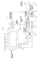
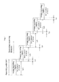
- Fig. 1 is a structural diagram illustrating a schematic configuration of an image recording apparatus 1 according to a first embodiment of the present teachings.
- the image recording apparatus 1 records an image by irradiating laser light onto the plate (recording medium) P being used in the CTP printing.
- the plate P is configured from a heat-reactive thermal CTP plate, a flexographic plate, and the like, and is fixed in place by a clamping mechanism not shown in the drawings so as to be wrapped around the body of the drum 2, which has a cylindrical shape.
- an image is recorded on the plate P by a plurality of laser lights emitted from a multi-channel recording head 4, while a rotation axis or shaft 2a of the drum 2 is rotatingly driven by a drum motor 3.
- a linear motor displacer
- a PC (personal computer) 11 used as a user operation terminal and subject to control of the recording processing is connected to the image recording apparatus 1 so as to be capable of communicating with the image recording apparatus 1.
- the PC 11 has installed therein an application program for controlling the image recording apparatus 1 and stores image information, including image data to be recorded on the plate P, and apparatus control information for controlling a recording operation of the image recording apparatus 1.
- image recording apparatus 1 with the rotation of the drum 2, an image for a predetermined line amount in the main scanning direction is recorded onto the plate P by laser light individually emitted from a plurality of semiconductor lasers LD1-LDn (see Fig. 2 , described later). Accordingly, image data corresponding to the number of lines is included in the image information.
- the image recording apparatus 1 obtains image information and apparatus control information from the PC 11.
- the image recording apparatus 1 includes an apparatus controller (recording controller) 12, a laser diode (LD) controller 15, and a laser block 18.
- the apparatus controller 12 performs overall control on each component of the image recording apparatus 1 in cooperation with the PC 11 and based on the image information and apparatus control information.
- the laser diode controller 15 controls emission of the plurality of semiconductor lasers LD1-LDn, which are the light sources for the lasers emitted from the recording head 4.
- the laser block 18 includes the semiconductor lasers LD1-LDn and their drivers.
- the apparatus controller 12 is chiefly configured with a CPU (Central Processing Unit) 13 performing calculations and controls based on a predetermined control program, and an image memory 14 functioning as a buffer memory storing image information obtained from the PC 11 when appropriate. Further, based on apparatus control information from the PC 11, the apparatus controller 12 outputs to a drive controller (not shown in the drawings) of the drum motor 3 a drum rotation control signal to control the rotation speed of the drum 2. In addition, the apparatus controller 12 outputs to a drive controller (not shown in the drawings) of the linear motor 5 a run control signal to control the running speed of the linear motor 5.
- a CPU Central Processing Unit
- the apparatus controller 12 outputs to a laser diode controller 15 an image signal including control information to control the emission of laser light from the recording head 4 (more strictly speaking, the emission of laser light from each of the semiconductor lasers LD1-LDn).
- the laser diode controller 15 includes a PLL (Phase Locked Loop) circuit 16 generating a standard clock signal by obtaining a rotation signal from an encoder (not shown in the drawings) attached to the drum motor 3. The laser diode controller 15 then syncs to the standard clock signal and outputs an image signal from the image memory 14 to the fiber output-format laser block 18 through a D/A converter circuit 17 as a laser diode control signal.
- PLL Phase Locked Loop
- the laser block 18 emits laser light from each of the semiconductor lasers LD1-LDn (see Fig. 2 ) at an output value and output timing based on the laser diode control signal (electric current). The emitted laser light is then sent to the recording head 4 through respective optical fibers F1-Fn.
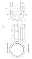
- Fig. 2 is a schematic view illustrating details of a configuration in the vicinity of the recording head 4 and the laser block 18.
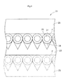
- Fig. 3 is a cross-sectional view illustrating a configuration of a fiber array 22.
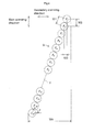
- Fig. 4 is a schematic view illustrating an arrangement of a bundle of optical fibers in a laser output in the recording head 4.
- each optical fiber F1-Fn is fixed to the fiber array 22 provided to the recording head 4 and is arranged in an array.
- each optical fiber F is fitted into a plurality of V grooves 24 formed on a substrate 23.
- each optical fiber F is fixed in place, sandwiched between the substrate 23 and a cover plate 25.
- the V grooves 24 have a V shape having a 60° angle, and are formed along an extension direction (left-right direction in Fig. 2 ) of the optical fibers F1-Fn.
- the substrate 23 and the cover plate 25 are formed, for example, from a fused quartz plate material having a thickness of 50 ⁇ m or more.
- a component having a known configuration may be used as the optical fiber F; however, a central core 27 has a diameter of 60-105 ⁇ m and a cladding 28 covering the circumference thereof has a diameter of 125 ⁇ m.
- the forefronts of the optical fibers F1-Fn are aligned by the V grooves 24 with a high degree of accuracy and the laser emitters configuring the emitting end faces thereof are aligned in a single line at a uniform interval W1, as shown in Fig. 4 .
- the interval (distance between centers) W1 of adjacent optical fibers is 127 ⁇ m.
- the angle of inclination ⁇ of the alignment direction X with respect to the secondary scanning direction is 75.52°, the alignment direction X being determined by a line linking the centers of the optical fibers F1-Fn.
- an interval W2 of each optical fiber F1-Fn in the main scanning direction is 122.97 ⁇ m and an interval W3 in the secondary scanning direction is 31.74 ⁇ m.
- the arrangement of the optical fibers F1-Fn is not limited to that shown in Fig. 4 and may be arranged in a plurality of lines, as shown in Fig. 5 and discussed hereafter.
- a group of optical lenses 31 configured from a plurality of optical lenses, such as collimator lenses, imaging lenses, and the like, is provided to the front (forwards the plate P direction) of the laser emitters of the optical fibers F1-Fn.
- Each laser light from the optical fibers F1-Fn thus forms an image on an image recording surface of the plate P, which is wrapped around the drum 2, through the group of optical lenses 31 without the optical paths thereof overlapping.
- the irradiation location of each laser light on the plate P corresponds to a pixel of the image being recorded.
- a recording width Wr of the recording head 4 is one-third the size (410 ⁇ m) of a width W4 (1230 ⁇ m) in the secondary scanning direction of one bundle of optical fibers F1-Fn shown in Fig. 4 .
- the fiber array 22 and the group of optical lenses 31 are supported on a focusing stage 41, the focusing stage 41 that adjusts the focus of the laser light. Further, the focusing stage 41 is connected to a steering element of the linear motor 5 (see Fig. 1 ), and is supported on a moving stage 42 movable in the secondary scanning direction along a guide rail not shown in the drawings.
- Fig. 5 is a schematic view illustrating an alternate example of the arrangement of the bundle of optical fibers F1-Fn shown in Fig. 4 .
- the interval W3 in the secondary scanning direction for adjacent optical fibers is 31.74 ⁇ m.
- the interval W3 is similarly set between an optical fiber in channel 32 positioned at the bottom-most portion of a first optical fiber bundle Ga and an optical fiber in channel 33 positioned at the top-most portion of a second optical fiber bundle Gb.
- image recording is performed by driving the drum 2 to rotate at a predetermined speed and, with the recording head 4 stopped at a predetermined position, emitting laser light from the recording head 4 toward the image recording surface of the plate P.
- the laser light of a plurality of channels emitted from the recording head 4 has a predetermined recording width Wr, as described above.
- a predetermined recording width Wr By rotating the drum 2 once (that is, one cycle of scanning is performed in the main scanning direction by the recording head 4), an image is recorded in the main scanning direction of the plate P at the recording width Wr.
- the recording head 4 is displaced in the secondary scanning direction to the next recording position by the linear motor 5. Thereafter, the same kind of recording operation is performed next during one rotation of the drum 2.
- an image is recorded in all regions of the plate P by repeatedly performing image recording for one rotation of the drum 2 and displacement of the recording head 4 in the secondary scanning direction.
- the plate P in the main scanning direction (circumferential direction of the drum 2), the plate P has predetermined recording regions at which an image can be recorded. Meanwhile, a portion where the plate P is not wrapped around the drum 2 (including a clamped portion of the plate P) constitutes a non-recording region where an image is not recorded.
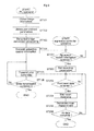
- a time during which the non-recording region is in an irradiation position of the recording head 4 during rotation of the drum 2 (that is, the imaging location of the laser light passes through the non-recording region) is a time T1. In a case where the time T1 is greater than a displacement time T2 for one cycle of displacement of the recording head 4 in the secondary scanning direction, the first recording mode can be executed.
- the second recording mode can be executed.
- the time T1 changes due to alterations in rotation speed of the drum 2, size of the non-recording region (circumferential direction length), and the like.
- one of the first and second recording modes is selected by a comparison of the time T1 and the time T2.
- the first and second recording modes can be selectively performed for each rotation of the drum 2 (for each scan in the main scanning direction).
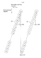
- Fig. 7 is an explanatory diagram of the displacement operation of the recording head 4.
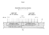
- Fig. 8 is an explanatory diagram illustrating laser light irradiation on the plate P.
- Fig. 7 shows each image recording region which is the target of recording processing shifted in a vertical direction on the paper surface for different rotations of the drum 2.
- each actual image recording region encompasses roughly the entire area of the plate P in the main scanning direction.
- a displacement amount Lm for the recording head 4 is defined to be less than the recording width Wr. Therefore, a rear edge in the secondary scanning direction of an image recording region (laser irradiation region) during a first rotation of the drum 2 overlaps with a front edge in the secondary scanning direction of the image recording region during a second rotation of the drum 2 with a predetermined overlap width Lo (Wr - Lm). Similarly, even during subsequent rotations of the drum 2, the rear edge in the secondary scanning direction of the image recording region overlaps with a front edge in the secondary scanning direction of the image recording region during the next rotation of the drum 2 with the predetermined overlap width Lo.
- the overlap width Lo can be set to a desired size by controlling the displacement amount Lm of the linear motor 5.
- the overlap width Lo is set to the size of one channel of laser light (here, 10 ⁇ m), as shown in Fig. 8 , for example, an irradiation position of laser light in channel n during the K - 1th rotation of the drum 2 (where K is an integer equal to or greater than 2) overlaps with the irradiation position of laser light in channel 1 during the Kth rotation of the drum 2.
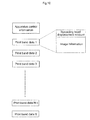
- the PC 11 obtains and stores each of image information and user-defined parameters (ST101, ST102).
- the user-defined parameters include various parameters a user sets on the PC 11 in order to control the recording operation of the image recording apparatus 1 (for example: rotation speed of the drum 2, laser light exposure energy gradient, maximum exposure energy, main scan length (length of line), secondary scan length (number of lines), number of print bands (number of image recording regions formed on the plate P), displacement amount of the recording head 4, and so on).
- the laser light exposure energy gradient is not limited only to two data values of ON and OFF. When, for example, there are 256 gradients, the laser light exposure energy gradient is recorded as 8 bits of data per pixel.
- the PC 11 performs recorded image conversion processing and generates a plurality of image information in accordance with the number of print bands, the image information including information for a predetermined line or lines corresponding to the number of channels of laser light emitted from the recording head 4 (ST103).
- the apparatus controller 12 sets recording parameters for controlling each apparatus component based on the apparatus control information (ST202). Thereby, the drum 2, the recording head 4, the linear motor 5, and the like become able to perform predetermined operations based on the user-defined parameters.
- Fig. 11 is an explanatory diagram of the displacement operation of the recording head 4 in the image recording apparatus 1 according to another embodiment, and corresponds to Fig. 7 for the above-described embodiment.
- the image recording apparatus 1 according to the second embodiment is similar to the first embodiment excepting those aspects relating to operation which are described particularly hereafter. A detailed description of other aspects is omitted.
- the image recording region for the second rotation of the drum 2 is a position shifted only Lm in the secondary scanning direction with respect to the image recording region for the first rotation of the drum 2.
- the position of the image recording region for the third rotation of the drum 2 with respect to the image recording region for the second rotation, and the position of the image recording region for the fourth rotation of the drum 2 with respect to the image recording region of the third rotation are positions similarly shifted only Lm.
- the recording head 4 is displaced in the secondary scanning direction only the distance obtained by subtracting a cumulative total of the amount of displacement from the recording width Wr (Wr - 3 x Lm).
- Wr cumulative total of the amount of displacement from the recording width Wr (Wr - 3 x Lm).
- the left edge position of the image recording region during the fifth rotation of the drum 2 matches the right edge position of the image recording region during the first rotation of the drum 2.
- the first displacement operation is performed once more similarly to the second through fourth rotations described above.
- the second displacement operation is performed once more after the image recording of the eighth rotation.
- scanning is performed a plurality of times in the main scanning direction while shifting the position of the recording head 4 in the secondary scanning direction. Accordingly, it becomes possible to prevent a reduction in the recording strength on both edges of the recording head 4 (both edges of the image recording region) and to increase the recording strength in roughly all regions of the plate P.
- the present invention was described with reference to particular embodiments; however, these embodiments are merely examples and are not intended to limit the present invention.
- the number of channels for laser emitters (emitting ends of optical fibers) in the recording head and their arrangement can be altered in many ways.
- the above-described embodiments are configured so as to necessarily displace a recording head in the secondary scanning direction each time a drum rotates.
- the recording head is not necessarily excluded from performing recording processing for a plurality of rotations of the drum at the same position.
- the image recording apparatus does not require complex controls for operations to record an image. By preventing a reduction in recording strength at both edges of a recording head, it is possible to effectively inhibit the occurrence of banding in a printed image.
- the present teachings can therefore be useful as an image recording apparatus performing image recording by irradiating laser light onto a recording medium, such as a plate wrapped around a drum.
Landscapes
- Health & Medical Sciences (AREA)
- General Health & Medical Sciences (AREA)
- Toxicology (AREA)
- Physics & Mathematics (AREA)
- Optics & Photonics (AREA)
- Exposure And Positioning Against Photoresist Photosensitive Materials (AREA)
Applications Claiming Priority (1)
| Application Number | Priority Date | Filing Date | Title |
|---|---|---|---|
| JP2011109634A JP5536711B2 (ja) | 2011-05-16 | 2011-05-16 | 画像記録装置 |
Publications (1)
| Publication Number | Publication Date |
|---|---|
| EP2524811A1 true EP2524811A1 (en) | 2012-11-21 |
Family
ID=46147304
Family Applications (1)
| Application Number | Title | Priority Date | Filing Date |
|---|---|---|---|
| EP12168105A Withdrawn EP2524811A1 (en) | 2011-05-16 | 2012-05-15 | Image recording apparatus |
Country Status (3)
| Country | Link |
|---|---|
| US (1) | US8553056B2 (enExample) |
| EP (1) | EP2524811A1 (enExample) |
| JP (1) | JP5536711B2 (enExample) |
Cited By (1)
| Publication number | Priority date | Publication date | Assignee | Title |
|---|---|---|---|---|
| EP3202580A1 (en) * | 2016-02-05 | 2017-08-09 | Ricoh Company, Ltd. | Recording method and recording device |
Families Citing this family (3)
| Publication number | Priority date | Publication date | Assignee | Title |
|---|---|---|---|---|
| US9483011B2 (en) * | 2014-07-14 | 2016-11-01 | Kyocera Document Solutions Inc. | Motor control device, image forming apparatus, motor control method, method for controlling image forming apparatus |
| EP3412464B1 (en) * | 2016-02-05 | 2020-03-04 | Ricoh Company, Ltd. | Recording method and recording apparatus |
| US9899052B2 (en) * | 2016-02-05 | 2018-02-20 | Ricoh Company, Ltd. | Recording method and recording device |
Citations (11)
| Publication number | Priority date | Publication date | Assignee | Title |
|---|---|---|---|---|
| WO1991008904A1 (en) * | 1989-12-18 | 1991-06-27 | Eastman Kodak Company | Thermal printer |
| WO1992008313A1 (en) * | 1990-10-26 | 1992-05-14 | Eastman Kodak Company | Multichannel optical printhead |
| US5818498A (en) * | 1995-10-16 | 1998-10-06 | Creo Products Inc. | Method of multi-channel thermal recording |
| US5942745A (en) * | 1997-12-17 | 1999-08-24 | Presstek, Inc. | Method and apparatus for digital imaging with reduced periodic artifacts |
| EP0945276A1 (en) * | 1997-03-26 | 1999-09-29 | Toray Industries, Inc. | Imaging device, imaging method, and printing device |
| EP1147906A2 (en) * | 2000-04-21 | 2001-10-24 | Fuji Photo Film Co., Ltd. | Multi-beam exposure apparatus |
| EP1235111A2 (de) * | 2001-02-22 | 2002-08-28 | Heidelberger Druckmaschinen Aktiengesellschaft | Banding-reduzierende Bebilderung einer Druckform |
| EP1266751A2 (en) * | 2001-06-14 | 2002-12-18 | Konica Corporation | Printing plate precursor, image forming method employing the same, and printing method |
| US20020196325A1 (en) * | 2001-06-21 | 2002-12-26 | Imation Corp. | Laser-induced thermal imaging with masking |
| US20040240922A1 (en) * | 2003-05-28 | 2004-12-02 | Dainippon Screen Mfg. Co., Ltd. | Image recording apparatus and image recording method |
| EP1844942A2 (en) * | 2006-03-24 | 2007-10-17 | Dainippon Screen Mfg., Co., Ltd. | Apparatus for and method of recording image |
Family Cites Families (3)
| Publication number | Priority date | Publication date | Assignee | Title |
|---|---|---|---|---|
| JP4869683B2 (ja) * | 2005-11-10 | 2012-02-08 | Necエンジニアリング株式会社 | 印刷装置及び印刷方法 |
| JP5168997B2 (ja) * | 2007-04-13 | 2013-03-27 | パナソニック株式会社 | 画像記録装置 |
| US8259354B2 (en) * | 2009-05-07 | 2012-09-04 | Eastman Kodak Company | Calibration of a recording apparatus |
-
2011
- 2011-05-16 JP JP2011109634A patent/JP5536711B2/ja not_active Expired - Fee Related
-
2012
- 2012-04-30 US US13/459,770 patent/US8553056B2/en not_active Expired - Fee Related
- 2012-05-15 EP EP12168105A patent/EP2524811A1/en not_active Withdrawn
Patent Citations (11)
| Publication number | Priority date | Publication date | Assignee | Title |
|---|---|---|---|---|
| WO1991008904A1 (en) * | 1989-12-18 | 1991-06-27 | Eastman Kodak Company | Thermal printer |
| WO1992008313A1 (en) * | 1990-10-26 | 1992-05-14 | Eastman Kodak Company | Multichannel optical printhead |
| US5818498A (en) * | 1995-10-16 | 1998-10-06 | Creo Products Inc. | Method of multi-channel thermal recording |
| EP0945276A1 (en) * | 1997-03-26 | 1999-09-29 | Toray Industries, Inc. | Imaging device, imaging method, and printing device |
| US5942745A (en) * | 1997-12-17 | 1999-08-24 | Presstek, Inc. | Method and apparatus for digital imaging with reduced periodic artifacts |
| EP1147906A2 (en) * | 2000-04-21 | 2001-10-24 | Fuji Photo Film Co., Ltd. | Multi-beam exposure apparatus |
| EP1235111A2 (de) * | 2001-02-22 | 2002-08-28 | Heidelberger Druckmaschinen Aktiengesellschaft | Banding-reduzierende Bebilderung einer Druckform |
| EP1266751A2 (en) * | 2001-06-14 | 2002-12-18 | Konica Corporation | Printing plate precursor, image forming method employing the same, and printing method |
| US20020196325A1 (en) * | 2001-06-21 | 2002-12-26 | Imation Corp. | Laser-induced thermal imaging with masking |
| US20040240922A1 (en) * | 2003-05-28 | 2004-12-02 | Dainippon Screen Mfg. Co., Ltd. | Image recording apparatus and image recording method |
| EP1844942A2 (en) * | 2006-03-24 | 2007-10-17 | Dainippon Screen Mfg., Co., Ltd. | Apparatus for and method of recording image |
Cited By (1)
| Publication number | Priority date | Publication date | Assignee | Title |
|---|---|---|---|---|
| EP3202580A1 (en) * | 2016-02-05 | 2017-08-09 | Ricoh Company, Ltd. | Recording method and recording device |
Also Published As
| Publication number | Publication date |
|---|---|
| JP2012242446A (ja) | 2012-12-10 |
| US20120293594A1 (en) | 2012-11-22 |
| JP5536711B2 (ja) | 2014-07-02 |
| US8553056B2 (en) | 2013-10-08 |
Similar Documents
| Publication | Publication Date | Title |
|---|---|---|
| EP2524811A1 (en) | Image recording apparatus | |
| JP2000043317A5 (enExample) | ||
| JP2000043317A (ja) | マルチビーム描画方法および装置 | |
| US7659525B2 (en) | Apparatus for and method of recording image | |
| CN1223172C (zh) | 多光束二极管泵浦的成象系统 | |
| JPH0563920A (ja) | 円筒内面走査型画像記録装置 | |
| US8558859B2 (en) | Laser printer with multiple laser-beam sources | |
| EP1294171B1 (en) | Image forming device and image forming method | |
| JP2007109929A (ja) | 二次元vcselアレイの駆動装置および駆動方法および画像形成方法および光走査装置および画像形成装置 | |
| KR20150008041A (ko) | 광기록 헤드 및 화상 형성 장치 | |
| JP2000043318A5 (enExample) | ||
| JP4680604B2 (ja) | 光走査装置および画像形成装置 | |
| JP4393278B2 (ja) | 二次元面発光レーザーアレイ、光走査装置及び電子写真装置 | |
| JP4896440B2 (ja) | 二次元面発光レーザーアレイおよび光走査装置および画像形成装置 | |
| JP4553295B2 (ja) | 画像記録装置 | |
| US20120320352A1 (en) | Multibeam exposure scanning method and apparatus, and method of manufacturing printing plate | |
| JP2006334896A (ja) | 画像記録装置 | |
| JP2005238632A (ja) | 露光装置 | |
| JP2006334894A (ja) | 画像記録装置 | |
| JP4471278B2 (ja) | 光走査方法 | |
| JP3103796B2 (ja) | 画像記録装置 | |
| US7839427B2 (en) | Multi-beam image forming apparatus configured to perform droop correction | |
| KR19990083549A (ko) | 촬상장치와회전드럼간의거리조절방법 | |
| JP2006334893A (ja) | 画像記録装置 | |
| JPH08156315A (ja) | 画像形成装置 |
Legal Events
| Date | Code | Title | Description |
|---|---|---|---|
| PUAI | Public reference made under article 153(3) epc to a published international application that has entered the european phase |
Free format text: ORIGINAL CODE: 0009012 |
|
| AK | Designated contracting states |
Kind code of ref document: A1 Designated state(s): AL AT BE BG CH CY CZ DE DK EE ES FI FR GB GR HR HU IE IS IT LI LT LU LV MC MK MT NL NO PL PT RO RS SE SI SK SM TR |
|
| AX | Request for extension of the european patent |
Extension state: BA ME |
|
| 17P | Request for examination filed |
Effective date: 20130313 |
|
| 17Q | First examination report despatched |
Effective date: 20140611 |
|
| STAA | Information on the status of an ep patent application or granted ep patent |
Free format text: STATUS: THE APPLICATION IS DEEMED TO BE WITHDRAWN |
|
| 18D | Application deemed to be withdrawn |
Effective date: 20141022 |