EP2524781B1 - Pressvorrichtung mit einer Lochplatte - Google Patents
Pressvorrichtung mit einer Lochplatte Download PDFInfo
- Publication number
- EP2524781B1 EP2524781B1 EP12000266.2A EP12000266A EP2524781B1 EP 2524781 B1 EP2524781 B1 EP 2524781B1 EP 12000266 A EP12000266 A EP 12000266A EP 2524781 B1 EP2524781 B1 EP 2524781B1
- Authority
- EP
- European Patent Office
- Prior art keywords
- perforated plate
- pressing device
- holes
- pressed
- base frame
- Prior art date
- Legal status (The legal status is an assumption and is not a legal conclusion. Google has not performed a legal analysis and makes no representation as to the accuracy of the status listed.)
- Active
Links
Images
Classifications
-
- B—PERFORMING OPERATIONS; TRANSPORTING
- B25—HAND TOOLS; PORTABLE POWER-DRIVEN TOOLS; MANIPULATORS
- B25B—TOOLS OR BENCH DEVICES NOT OTHERWISE PROVIDED FOR, FOR FASTENING, CONNECTING, DISENGAGING, OR HOLDING
- B25B1/00—Vices
- B25B1/06—Arrangements for positively actuating jaws
-
- B—PERFORMING OPERATIONS; TRANSPORTING
- B25—HAND TOOLS; PORTABLE POWER-DRIVEN TOOLS; MANIPULATORS
- B25B—TOOLS OR BENCH DEVICES NOT OTHERWISE PROVIDED FOR, FOR FASTENING, CONNECTING, DISENGAGING, OR HOLDING
- B25B5/00—Clamps
- B25B5/14—Clamps for work of special profile
-
- B—PERFORMING OPERATIONS; TRANSPORTING
- B25—HAND TOOLS; PORTABLE POWER-DRIVEN TOOLS; MANIPULATORS
- B25B—TOOLS OR BENCH DEVICES NOT OTHERWISE PROVIDED FOR, FOR FASTENING, CONNECTING, DISENGAGING, OR HOLDING
- B25B5/00—Clamps
- B25B5/14—Clamps for work of special profile
- B25B5/142—Clamps for work of special profile for windows and frames
-
- B—PERFORMING OPERATIONS; TRANSPORTING
- B27—WORKING OR PRESERVING WOOD OR SIMILAR MATERIAL; NAILING OR STAPLING MACHINES IN GENERAL
- B27M—WORKING OF WOOD NOT PROVIDED FOR IN SUBCLASSES B27B - B27L; MANUFACTURE OF SPECIFIC WOODEN ARTICLES
- B27M3/00—Manufacture or reconditioning of specific semi-finished or finished articles
- B27M3/0013—Manufacture or reconditioning of specific semi-finished or finished articles of composite or compound articles
Definitions
- the invention relates to a pressing device for woodworking according to the preamble of claim 1.
- a pressing device is known from DE 201 03 899 U known.
- a pressing device comprises a flat frame-shaped base frame, which forms a lateral, abutment plane for an object to be pressed and mounted on the base frame and arranged above the abutment plane short, jaw-like, adjustable support shoes on which the object to be pressed is placed and between which the object to be pressed can be pressed.
- Such a pressing device makes it possible to press larger objects mainly on the dimension.
- the object of the invention is to improve the state of the art and in particular to provide a pressing device with the simultaneously large-sized objects, as well as small-sized and / or triangular or polygonal objects, such as. Hexagonal objects can be pressed.
- the pressing device has, in addition to the frame press on a perforated plate, which is integrated as a rear wall in the flat frame-shaped base frame of the pressing device, this can only a part of the frame-shaped base frame, as half of the frame-shaped base frame or completely fill the frame-shaped base frame.
- This perforated plate has openings in a grid.
- the openings are circular holes or rectangular openings, with circular holes are preferred.
- the openings in the perforated plate preferably have a diameter of 5 mm to 30 mm, preferably 10 mm to 25 mm, particularly preferably 15 mm to 20 mm. These openings are preferably arranged in the perforated plate in a grid of 10 to 100 mm, preferably 25 to 75 mm, particularly preferably 30 to 50 mm.
- the perforated plate preferably has at least one vertical and one horizontal stop, wherein the vertical stop is preferably located on the left and the horizontal stop preferably below, in addition, preferably still a vertical stop right and preferably a horizontal stop above be arranged.
- the perforated plate pressurizing devices can be attached, which are rotatable in a preferred embodiment by up to 360 °.
- This pressurizing device may be operated by means of a rack-and-pinion gear to be easily operated mechanically or by means of hydraulics to press a workpiece. Due to the fact that the perforated plate has openings throughout, pressurizing devices in any number can be installed at any point. Thus, it is also possible to have small dimensioned and / or triangular or polygonal objects, such as e.g. to press hexagonal or octagonal objects.
- FIG. 1 A first figure.
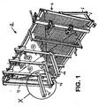
- the FIG. 1 shows a schematic perspective view of the shown exemplary embodiment of the pressing device 2.
- the pressing device 2 comprises a flat, braced, frame-shaped base frame 4, for example, metal profiles.
- the base frame 4 can just as well be made of a different material.
- the base frame is preferably positioned slightly inclined relative to the vertical by means of support legs 6.
- the base frame has 4 horizontal and substantially vertical profiles and struts on the back.
- the substantially vertical profiles are hereinafter referred to as post 10.
- the base frame 4, ie in the present case, the side facing the viewer of the post 10 form a lateral, relative to the vertical slightly inclined abutment plane for an object to be pressed (not shown in the drawing for clarity).
- the left outer post 12 in the figure projects from the abutment plane and thus forms a lateral abutment post 12, if required.
- the perforated plate is integrated in the base frame 4.
- the base frame 4 On the base frame 4, i. arranged in the present case on the post 10, and above the abutment level above short, jaw-like, adjustable support shoes 14 are attached, and below elongated, arm-like clamping and support rail 16 on which usually to arrange the object to be pressed and between which the object to be pressed is to press.
- the short, jaw-like support shoes 14 are shown above, but can also be designed as an elongated, arm-like clamping and support rail 16.
- arm-like clamping and support rails 16 can be seen below, in the vicinity of the lower edge of the base frame 4.
- the lower support means can be configured as a simple support shoes.
- the perforated plate is integrated with openings in a grid as a rear wall, in the openings of the pressurizing devices can be mounted to press a workpiece.
- the advantage of the invention is that now with a pressing device at the same time large workpieces as well as smaller non-rectangular shaped objects, such as triangular or polygonal objects can be pressed.
Landscapes
- Engineering & Computer Science (AREA)
- Mechanical Engineering (AREA)
- Life Sciences & Earth Sciences (AREA)
- Manufacturing & Machinery (AREA)
- Wood Science & Technology (AREA)
- Forests & Forestry (AREA)
- Press Drives And Press Lines (AREA)
Description
- Die Erfindung betrifft eine Pressvorrichtung für die Holzbearbeitung gemäß dem Oberbegriff des Anspruchs 1. Eine solche Pressvorrichtung ist aus der
DE 201 03 899 U bekannt. - Eine Pressvorrichtung nach dem Stand der Technik weist ein flaches rahmenförmiges Grundgestell auf, das eine seitliche, Anlageebene für einen zu verpressenden Gegenstand bildet und an dem Grundgestell angebrachte und über der Anlageebene angeordnete kurze, spannbackenartige, justierbare Auflageschuhe, auf denen der zu verpressende Gegenstand angeordnet wird und zwischen denen der zu verpressende Gegenstand verpresst werden kann. Eine derartige Pressvorrichtung ermöglicht es hauptsächlich von der Dimension größere Gegenstände zu verpressen. Darüberhinaus besteht gleichzeitig ein Bedürfnis auch kleinere nicht rechteckig geformte Gegenstände, wie dreieckige oder polygonale Gegenstände zu verpressen.
- Aufgabe der Erfindung ist es, den Stand der Technik zu verbessern und insbesondere eine Pressvorrichtung zur Verfügung zu stellen, mit der gleichzeitig groß dimensionierte Gegenstände, wie auch klein dimensionierte und/oder dreieckige oder polygonale Gegenstände, wie z.B. hexagonale Gegenstände verpresst werden können.
- Gegenstand der Erfindung ist eine Pressvorrichtung (2) aufweisend,
- ein flaches rahmenförmiges Grundgestell (4, 10, 12), das eine seitliche, gegebenenfalls gegenüber der Vertikalen leicht geneigte, Anlageebene für einen zu verpressenden Gegenstand bildet, und
- an dem Grundgestell (4, 10) angebrachte und über der Anlageebene angeordnete kurze, spannbackenartige, justierbare Auflageschuhe (14) oder langgestreckte, armartige Spann- und Auflageschienen (16), auf denen der zu verpressende Gegenstand anzuordnen und zwischen denen der zu verpressende Gegenstand zu verpressen ist,
- jeweils eine auf die oberen Auflageschuhe (14) und die untere Auflageschiene (16) wirkende Druckbeaufschlagungseinrichtung
- Die erfindungsgemäße Pressvorrichtung weist zusätzlich zu der Rahmenpresse eine Lochplatte auf, die als Rückwand in das flache rahmenförmige Grundgestell der Pressvorrichtung integriert ist, diese kann nur einen Teil des rahmenförmigen Grundgestells, wie die Hälfte des rahmenförmigen Grundgestells oder auch vollständig das rahmenförmige Grundgestell ausfüllen.
- Diese Lochplatte weist Öffnungen in einem Raster auf. Bei den Öffnungen handelt es sich um kreisrunde Bohrungen oder rechteckige Öffnungen, wobei kreisrunde Bohrungen bevorzugt sind. Die Öffnungen in der Lochplatte weisen vorzugsweise einen Durchmesser von 5 mm bis 30 mm, bevorzugt 10 mm bis 25 mm, besonders bevorzugt 15 mm bis 20 mm auf. Diese Öffnungen sind in der Lochplatte vorzugsweise in einem Raster von 10 bis 100 mm, bevorzugt 25 bis 75 mm, besonders bevorzugt 30 bis 50 mm angeordnet.
- Um ein Werkstück verpressen zu können, weist die Lochplatte vorzugsweise zumindest einen vertikalen und einen horizontalen Anschlag auf, wobei der vertikale Anschlag vorzugsweise links und der horizontale Anschlag vorzugsweise unten angeordnet ist, zusätzlich kann noch vorzugsweise ein vertikaler-Anschlag rechts und vorzugsweise ein horizontaler Anschlag oben angeordnet sein.
- In den Öffnungen der Lochplatte lassen sich Druckbeaufschlagungsvorrichtungen anbringen, die in einer bevorzugten Ausführungsform um bis zu 360° drehbar sind. Diese Druckbeaufschlagungsvorrichtung kann mittels einem leicht mechanisch zu betreibendem Zahnstangengetriebe oder mittels einer Hydraulik betrieben werden, um ein Werkstück zu verpressen. Aufgrund dessen, dass die Lochplatte flächendeckend Öffnungen aufweist, können an beliebigen Stellen Druckbeaufschlagurigsvorrichtungen in beliebiger Anzahl angebracht werden. Somit ist es möglich auch klein dimensionierte und/oder dreieckige oder polygonale Gegenstände, wie z.B. hexagonale oder oktagonale Gegenstände zu verpressen.
- Die
Figur 1 zeigt eine schematische Perspektivansicht der gezeigten beispielhaften Ausführungsform der Pressvorrichtung 2. Die Pressvorrichtung 2 umfasst ein flaches, verstrebtes, rahmenförmiges Grundgestell 4 aus beispielsweise Metallprofilen. Das Grundgestell 4 kann aber ebenso gut aus einem anderen Werkstoff gefertigt sein. Das Grundgestell ist mit Hilfe von Stützfüssen 6 vorzugsweise leicht gegenüber der Vertikalen geneigt aufgestellt. Wie zu erkennen, besitzt das Grundgestell 4 horizontale und im Wesentlichen vertikal verlaufende Profile sowie rückseitig Verstrebungen. Die im Wesentlichen vertikal verlaufenden Profile werden nachstehend als Pfosten 10 bezeichnet. Das Grundgestell 4, d.h. im vorliegenden Fall die dem Betrachter zugewandte Seite der Pfosten 10 bilden eine seitliche, gegenüber der vertikalen leicht geneigte Anlageebene für einen zu verpressenden Gegenstand (in der Zeichnung der Übersichtlichkeit halber nicht gezeigt). Der in der Figur linke äussere Pfosten 12 steht indes von der Anlageebene hervor und bildet so bei Bedarf einen seitlichen Anschlagpfosten 12. In das Grundgestell 4 ist die Lochplatte integriert. - An dem Grundgestell 4, d.h. im vorliegenden Fall an den pfosten 10, und über der Anlageebene angeordnet sind oben kurze, spannbackenartige, justierbare Auflageschuhe 14 angebracht, und unten langgestreckte, armartige Spann- und Auflageschiene 16 auf denen der zu verpressende Gegenstand üblicherweise anzuordnen und zwischen denen der zu verpressende Gegenstand zu verpressen ist. In dem Ausführungsbeispiel sind oben lediglich die kurzen, spannbackenartigen Auflageschuhe 14 gezeigt, die aber auch als langgestreckte, armartige Spann- und Auflageschiene 16 ausgebildet sein können. Armartige Spann- und Auflageschienen 16 sind jedoch unten zu erkennen, in der Nähe des unteren Randes des Grundgestells 4. Selbstverständlich können auch die unteren Auflageeinrichtungen als einfache Auflageschuhe ausgestaltet sein. In dem Grundgestell 4 ist die Lochplatte mit Öffnungen in einem Raster als Rückwand integriert, in deren Öffnungen die Druckbeaufschlagungsvorrichtungen eingehängt werden können, um ein Werkstück zu verpressen.
- Der Vorteil der Erfindung ist, dass nun mit einer Pressvorrichtung zugleich große Werkstücke wie auch kleinere nicht rechteckig geformte Gegenstände, wie dreieckige oder polygonale Gegenstände verpresst werden können.
Claims (7)
- Pressvorrichtung (2) aufweisend,- ein flaches rahmenförmiges Grundgestell (4, 10, 12), das eine seitliche, gegebenenfalls gegenüber der Vertikalen leicht geneigte, Anlageebene für einen zu verpressenden Gegenstand bildet, und- an dem Grundgestell (4, 10) angebrachte und über der Anlageebene angeordnete kurze, spannbackenartige, justierbare Auflageschuhe (14) und langgestreckte, armartige Spann- und Auflageschienen (16), auf denen der zu verpressende Gegenstand anzuordnen und zwischen denen der zu verpressende Gegenstand zu verpressen ist,- jeweils eine auf die oberen Auflageschuhe (14) und die untere Auflageschiene (16) wirkende Druckbeaufschlagungseinrichtungdadurch gekennzeichnet, dass das flache rahmenförmige Grundgestell (4, 10, 12) eine Lochplatte aufweist, die dafür vorgesehen ist, daß klein dimensionierte und/oder dreieckige oder polygonal Gegenstände verpresst werden können.
- Pressvorrichtung nach Anspruch 1, dadurch gekennzeichnet, dass die Lochplatte Öffnungen in einem Raster aufweist.
- Pressvorrichtung nach Anspruch 1 bis 2, dadurch gekennzeichnet, dass die Öffnungen kreisrunde Bohrungen oder rechteckige Öffnungen sind.
- Pressvorrichtung nach Anspruch 1 bis 3, dadurch gekennzeichnet, dass die Öffnungen in der Lochplatte einen Durchmesser von 5 mm bis 30 mm aufweist.
- Pressvorrichtung nach Anspruch 1 bis 4, dadurch gekennzeichnet, dass die Öffnungen in der Lochplatte in einem Raster von 10 bis 100 mm angeordnet sind.
- Pressvorrichtung nach Anspruch 1 bis 5, dadurch gekennzeichnet, dass die Lochplatte zumindest einen vertikalen und einen horizontalen Anschlag aufweist.
- Pressvorrichtung nach Anspruch 1 bis 6, dadurch gekennzeichnet, dass an der Lochplatte Druckbeaufschlagungsvorrichtungen, gegebenenfalls drehbar, anbringbar sind.
Applications Claiming Priority (2)
| Application Number | Priority Date | Filing Date | Title |
|---|---|---|---|
| DE202011100821U DE202011100821U1 (de) | 2011-05-17 | 2011-05-17 | Pressvorrichtung mit Zusatz |
| DE102011101822A DE102011101822A1 (de) | 2011-05-17 | 2011-05-17 | Pressvorrichtung mit Zusatz |
Publications (2)
| Publication Number | Publication Date |
|---|---|
| EP2524781A1 EP2524781A1 (de) | 2012-11-21 |
| EP2524781B1 true EP2524781B1 (de) | 2015-06-17 |
Family
ID=48143662
Family Applications (1)
| Application Number | Title | Priority Date | Filing Date |
|---|---|---|---|
| EP12000266.2A Active EP2524781B1 (de) | 2011-05-17 | 2012-01-17 | Pressvorrichtung mit einer Lochplatte |
Country Status (2)
| Country | Link |
|---|---|
| EP (1) | EP2524781B1 (de) |
| DE (2) | DE102011101822A1 (de) |
Families Citing this family (1)
| Publication number | Priority date | Publication date | Assignee | Title |
|---|---|---|---|---|
| DE102012005425B4 (de) * | 2012-03-20 | 2019-01-10 | Gerhard Barth | Pressvorrichtung mit verstellbarer Spannschiene |
Citations (1)
| Publication number | Priority date | Publication date | Assignee | Title |
|---|---|---|---|---|
| DE1753365U (de) * | 1957-05-25 | 1957-10-03 | Walter Karl Hahnenkratt | Presse, druckluftbetaetigt, drehbar fuer serien-verleimarbeiten. |
Family Cites Families (7)
| Publication number | Priority date | Publication date | Assignee | Title |
|---|---|---|---|---|
| DE1219660B (de) * | 1963-09-24 | 1966-06-23 | Waldemar Hammer | Presse zum Einspannen von vorzugsweise hoelzernen, rahmenartigen Werkstuecken unter rechten Winkeln |
| US3747184A (en) * | 1971-04-07 | 1973-07-24 | H Zaiss | System for forming building frame structures |
| DE7537192U (de) * | 1975-11-22 | 1976-03-18 | Curta & Co Gmbh - Das Jade-Haus, 6000 Frankfurt | Lochwandhaken |
| GB2136727B (en) * | 1983-02-15 | 1987-10-14 | Keith Shafto | Clamping and holding tool for woodwork |
| US4650106A (en) * | 1985-02-11 | 1987-03-17 | Branaman David H | Apparatus for aligning and clamping a workpiece |
| DE19622324C2 (de) * | 1996-06-04 | 1998-04-09 | Reinhold Hess Gmbh & Co Kg Mas | Montagepresse für die Herstellung von Holzfertigbauelementen |
| DE20017197U1 (de) * | 2000-10-06 | 2000-12-21 | Barth, Gerhard, 84550 Feichten | Vorrichtung zum Verpressen von Flächen, Rahmen und Korpussen |
-
2011
- 2011-05-17 DE DE102011101822A patent/DE102011101822A1/de not_active Withdrawn
- 2011-05-17 DE DE202011100821U patent/DE202011100821U1/de not_active Expired - Lifetime
-
2012
- 2012-01-17 EP EP12000266.2A patent/EP2524781B1/de active Active
Patent Citations (1)
| Publication number | Priority date | Publication date | Assignee | Title |
|---|---|---|---|---|
| DE1753365U (de) * | 1957-05-25 | 1957-10-03 | Walter Karl Hahnenkratt | Presse, druckluftbetaetigt, drehbar fuer serien-verleimarbeiten. |
Also Published As
| Publication number | Publication date |
|---|---|
| DE202011100821U1 (de) | 2011-09-12 |
| DE102011101822A1 (de) | 2012-11-22 |
| EP2524781A1 (de) | 2012-11-21 |
Similar Documents
| Publication | Publication Date | Title |
|---|---|---|
| EP2978574A1 (de) | Fliesenschneider | |
| EP3077133B1 (de) | Biegepresse | |
| DE202009014342U1 (de) | Schweiß- und Montagetisch | |
| DE102017118180A1 (de) | Eine Werkzeugmaschine zur Bohrung von Gläsern | |
| EP3215317B1 (de) | Spannvorrichtung | |
| DE202023106787U1 (de) | Simulationstestvorrichtung für die Erzfreigabe nach der Lawinenmethode | |
| DE102009010363A1 (de) | Fördervorrichtung mit stufenloser Höhenverstellung | |
| DE1452821B1 (de) | Abkantpresse mit Einstellvorrichtung | |
| EP3103956B1 (de) | Modulares tragprofil mit stabaufnahmen | |
| DE102012005425B4 (de) | Pressvorrichtung mit verstellbarer Spannschiene | |
| EP2524781A1 (de) | Pressvorrichtung mit einer Lochplatte | |
| DE19635376C1 (de) | Hohlraumboden | |
| DE202012002787U1 (de) | Pressvorrichtung mit verstellbarer Spannschiene | |
| DE10342713B4 (de) | Vorrichtung zum Schneiden von vorzugsweise Dämmstoffplatten o.dgl. | |
| DE29910927U1 (de) | Werkzeugmodul | |
| DE102014113603A1 (de) | Lastteil für ein Flurförderzeug | |
| DE202012010727U1 (de) | Pressvorrichtung mit Zusatzpresse | |
| DE102012111377C5 (de) | Membranpresse | |
| DE102014007829A1 (de) | Verfahren und Vorrichtung zum Erstellen einer ebenen Fläche | |
| EP2949835B1 (de) | Vorrichtung zum ausschalen von rahmenschalelementen | |
| DE19622324C2 (de) | Montagepresse für die Herstellung von Holzfertigbauelementen | |
| DE20103899U1 (de) | Pressvorrichtung | |
| DE6811332U (de) | Vorrichtung zum richten verbogener rohre oder dergl. | |
| DE1452821C (de) | Abkantpresse mit Einstellvorrichtung | |
| DE9014582U1 (de) | Presse zum Stanzen von Blech |
Legal Events
| Date | Code | Title | Description |
|---|---|---|---|
| PUAI | Public reference made under article 153(3) epc to a published international application that has entered the european phase |
Free format text: ORIGINAL CODE: 0009012 |
|
| AK | Designated contracting states |
Kind code of ref document: A1 Designated state(s): AL AT BE BG CH CY CZ DE DK EE ES FI FR GB GR HR HU IE IS IT LI LT LU LV MC MK MT NL NO PL PT RO RS SE SI SK SM TR |
|
| AX | Request for extension of the european patent |
Extension state: BA ME |
|
| 17P | Request for examination filed |
Effective date: 20130506 |
|
| 17Q | First examination report despatched |
Effective date: 20140612 |
|
| GRAP | Despatch of communication of intention to grant a patent |
Free format text: ORIGINAL CODE: EPIDOSNIGR1 |
|
| INTG | Intention to grant announced |
Effective date: 20150108 |
|
| RIN1 | Information on inventor provided before grant (corrected) |
Inventor name: BARTH, GERHARD |
|
| GRAS | Grant fee paid |
Free format text: ORIGINAL CODE: EPIDOSNIGR3 |
|
| GRAA | (expected) grant |
Free format text: ORIGINAL CODE: 0009210 |
|
| AK | Designated contracting states |
Kind code of ref document: B1 Designated state(s): AL AT BE BG CH CY CZ DE DK EE ES FI FR GB GR HR HU IE IS IT LI LT LU LV MC MK MT NL NO PL PT RO RS SE SI SK SM TR |
|
| REG | Reference to a national code |
Ref country code: GB Ref legal event code: FG4D Free format text: NOT ENGLISH |
|
| REG | Reference to a national code |
Ref country code: CH Ref legal event code: EP |
|
| REG | Reference to a national code |
Ref country code: AT Ref legal event code: REF Ref document number: 731648 Country of ref document: AT Kind code of ref document: T Effective date: 20150715 |
|
| REG | Reference to a national code |
Ref country code: IE Ref legal event code: FG4D Free format text: LANGUAGE OF EP DOCUMENT: GERMAN |
|
| REG | Reference to a national code |
Ref country code: DE Ref legal event code: R096 Ref document number: 502012003442 Country of ref document: DE |
|
| PG25 | Lapsed in a contracting state [announced via postgrant information from national office to epo] |
Ref country code: NO Free format text: LAPSE BECAUSE OF FAILURE TO SUBMIT A TRANSLATION OF THE DESCRIPTION OR TO PAY THE FEE WITHIN THE PRESCRIBED TIME-LIMIT Effective date: 20150917 Ref country code: LT Free format text: LAPSE BECAUSE OF FAILURE TO SUBMIT A TRANSLATION OF THE DESCRIPTION OR TO PAY THE FEE WITHIN THE PRESCRIBED TIME-LIMIT Effective date: 20150617 Ref country code: HR Free format text: LAPSE BECAUSE OF FAILURE TO SUBMIT A TRANSLATION OF THE DESCRIPTION OR TO PAY THE FEE WITHIN THE PRESCRIBED TIME-LIMIT Effective date: 20150617 Ref country code: FI Free format text: LAPSE BECAUSE OF FAILURE TO SUBMIT A TRANSLATION OF THE DESCRIPTION OR TO PAY THE FEE WITHIN THE PRESCRIBED TIME-LIMIT Effective date: 20150617 |
|
| REG | Reference to a national code |
Ref country code: LT Ref legal event code: MG4D Ref country code: NL Ref legal event code: MP Effective date: 20150617 |
|
| PG25 | Lapsed in a contracting state [announced via postgrant information from national office to epo] |
Ref country code: RS Free format text: LAPSE BECAUSE OF FAILURE TO SUBMIT A TRANSLATION OF THE DESCRIPTION OR TO PAY THE FEE WITHIN THE PRESCRIBED TIME-LIMIT Effective date: 20150617 Ref country code: BG Free format text: LAPSE BECAUSE OF FAILURE TO SUBMIT A TRANSLATION OF THE DESCRIPTION OR TO PAY THE FEE WITHIN THE PRESCRIBED TIME-LIMIT Effective date: 20150917 Ref country code: LV Free format text: LAPSE BECAUSE OF FAILURE TO SUBMIT A TRANSLATION OF THE DESCRIPTION OR TO PAY THE FEE WITHIN THE PRESCRIBED TIME-LIMIT Effective date: 20150617 Ref country code: GR Free format text: LAPSE BECAUSE OF FAILURE TO SUBMIT A TRANSLATION OF THE DESCRIPTION OR TO PAY THE FEE WITHIN THE PRESCRIBED TIME-LIMIT Effective date: 20150918 |
|
| PG25 | Lapsed in a contracting state [announced via postgrant information from national office to epo] |
Ref country code: EE Free format text: LAPSE BECAUSE OF FAILURE TO SUBMIT A TRANSLATION OF THE DESCRIPTION OR TO PAY THE FEE WITHIN THE PRESCRIBED TIME-LIMIT Effective date: 20150617 |
|
| PG25 | Lapsed in a contracting state [announced via postgrant information from national office to epo] |
Ref country code: PT Free format text: LAPSE BECAUSE OF FAILURE TO SUBMIT A TRANSLATION OF THE DESCRIPTION OR TO PAY THE FEE WITHIN THE PRESCRIBED TIME-LIMIT Effective date: 20151019 Ref country code: ES Free format text: LAPSE BECAUSE OF FAILURE TO SUBMIT A TRANSLATION OF THE DESCRIPTION OR TO PAY THE FEE WITHIN THE PRESCRIBED TIME-LIMIT Effective date: 20150617 Ref country code: SK Free format text: LAPSE BECAUSE OF FAILURE TO SUBMIT A TRANSLATION OF THE DESCRIPTION OR TO PAY THE FEE WITHIN THE PRESCRIBED TIME-LIMIT Effective date: 20150617 Ref country code: CZ Free format text: LAPSE BECAUSE OF FAILURE TO SUBMIT A TRANSLATION OF THE DESCRIPTION OR TO PAY THE FEE WITHIN THE PRESCRIBED TIME-LIMIT Effective date: 20150617 Ref country code: PL Free format text: LAPSE BECAUSE OF FAILURE TO SUBMIT A TRANSLATION OF THE DESCRIPTION OR TO PAY THE FEE WITHIN THE PRESCRIBED TIME-LIMIT Effective date: 20150617 Ref country code: RO Free format text: LAPSE BECAUSE OF NON-PAYMENT OF DUE FEES Effective date: 20150617 Ref country code: IS Free format text: LAPSE BECAUSE OF FAILURE TO SUBMIT A TRANSLATION OF THE DESCRIPTION OR TO PAY THE FEE WITHIN THE PRESCRIBED TIME-LIMIT Effective date: 20151017 |
|
| REG | Reference to a national code |
Ref country code: DE Ref legal event code: R097 Ref document number: 502012003442 Country of ref document: DE |
|
| PLBE | No opposition filed within time limit |
Free format text: ORIGINAL CODE: 0009261 |
|
| STAA | Information on the status of an ep patent application or granted ep patent |
Free format text: STATUS: NO OPPOSITION FILED WITHIN TIME LIMIT |
|
| PG25 | Lapsed in a contracting state [announced via postgrant information from national office to epo] |
Ref country code: DK Free format text: LAPSE BECAUSE OF FAILURE TO SUBMIT A TRANSLATION OF THE DESCRIPTION OR TO PAY THE FEE WITHIN THE PRESCRIBED TIME-LIMIT Effective date: 20150617 Ref country code: IT Free format text: LAPSE BECAUSE OF FAILURE TO SUBMIT A TRANSLATION OF THE DESCRIPTION OR TO PAY THE FEE WITHIN THE PRESCRIBED TIME-LIMIT Effective date: 20150617 |
|
| 26N | No opposition filed |
Effective date: 20160318 |
|
| PG25 | Lapsed in a contracting state [announced via postgrant information from national office to epo] |
Ref country code: BE Free format text: LAPSE BECAUSE OF NON-PAYMENT OF DUE FEES Effective date: 20160131 |
|
| PG25 | Lapsed in a contracting state [announced via postgrant information from national office to epo] |
Ref country code: LU Free format text: LAPSE BECAUSE OF FAILURE TO SUBMIT A TRANSLATION OF THE DESCRIPTION OR TO PAY THE FEE WITHIN THE PRESCRIBED TIME-LIMIT Effective date: 20160117 Ref country code: SI Free format text: LAPSE BECAUSE OF FAILURE TO SUBMIT A TRANSLATION OF THE DESCRIPTION OR TO PAY THE FEE WITHIN THE PRESCRIBED TIME-LIMIT Effective date: 20150617 |
|
| GBPC | Gb: european patent ceased through non-payment of renewal fee |
Effective date: 20160117 |
|
| PG25 | Lapsed in a contracting state [announced via postgrant information from national office to epo] |
Ref country code: MC Free format text: LAPSE BECAUSE OF FAILURE TO SUBMIT A TRANSLATION OF THE DESCRIPTION OR TO PAY THE FEE WITHIN THE PRESCRIBED TIME-LIMIT Effective date: 20150617 |
|
| REG | Reference to a national code |
Ref country code: FR Ref legal event code: ST Effective date: 20160930 |
|
| PG25 | Lapsed in a contracting state [announced via postgrant information from national office to epo] |
Ref country code: GB Free format text: LAPSE BECAUSE OF NON-PAYMENT OF DUE FEES Effective date: 20160117 |
|
| REG | Reference to a national code |
Ref country code: IE Ref legal event code: MM4A |
|
| PG25 | Lapsed in a contracting state [announced via postgrant information from national office to epo] |
Ref country code: FR Free format text: LAPSE BECAUSE OF NON-PAYMENT OF DUE FEES Effective date: 20160201 |
|
| PG25 | Lapsed in a contracting state [announced via postgrant information from national office to epo] |
Ref country code: IE Free format text: LAPSE BECAUSE OF NON-PAYMENT OF DUE FEES Effective date: 20160117 |
|
| PG25 | Lapsed in a contracting state [announced via postgrant information from national office to epo] |
Ref country code: SE Free format text: LAPSE BECAUSE OF FAILURE TO SUBMIT A TRANSLATION OF THE DESCRIPTION OR TO PAY THE FEE WITHIN THE PRESCRIBED TIME-LIMIT Effective date: 20150617 Ref country code: NL Free format text: LAPSE BECAUSE OF FAILURE TO SUBMIT A TRANSLATION OF THE DESCRIPTION OR TO PAY THE FEE WITHIN THE PRESCRIBED TIME-LIMIT Effective date: 20150617 |
|
| PG25 | Lapsed in a contracting state [announced via postgrant information from national office to epo] |
Ref country code: MT Free format text: LAPSE BECAUSE OF FAILURE TO SUBMIT A TRANSLATION OF THE DESCRIPTION OR TO PAY THE FEE WITHIN THE PRESCRIBED TIME-LIMIT Effective date: 20150617 |
|
| PG25 | Lapsed in a contracting state [announced via postgrant information from national office to epo] |
Ref country code: HU Free format text: LAPSE BECAUSE OF FAILURE TO SUBMIT A TRANSLATION OF THE DESCRIPTION OR TO PAY THE FEE WITHIN THE PRESCRIBED TIME-LIMIT; INVALID AB INITIO Effective date: 20120117 Ref country code: CY Free format text: LAPSE BECAUSE OF FAILURE TO SUBMIT A TRANSLATION OF THE DESCRIPTION OR TO PAY THE FEE WITHIN THE PRESCRIBED TIME-LIMIT Effective date: 20150617 Ref country code: SM Free format text: LAPSE BECAUSE OF FAILURE TO SUBMIT A TRANSLATION OF THE DESCRIPTION OR TO PAY THE FEE WITHIN THE PRESCRIBED TIME-LIMIT Effective date: 20150617 |
|
| PG25 | Lapsed in a contracting state [announced via postgrant information from national office to epo] |
Ref country code: MK Free format text: LAPSE BECAUSE OF FAILURE TO SUBMIT A TRANSLATION OF THE DESCRIPTION OR TO PAY THE FEE WITHIN THE PRESCRIBED TIME-LIMIT Effective date: 20150617 Ref country code: TR Free format text: LAPSE BECAUSE OF FAILURE TO SUBMIT A TRANSLATION OF THE DESCRIPTION OR TO PAY THE FEE WITHIN THE PRESCRIBED TIME-LIMIT Effective date: 20150617 |
|
| PG25 | Lapsed in a contracting state [announced via postgrant information from national office to epo] |
Ref country code: AL Free format text: LAPSE BECAUSE OF FAILURE TO SUBMIT A TRANSLATION OF THE DESCRIPTION OR TO PAY THE FEE WITHIN THE PRESCRIBED TIME-LIMIT Effective date: 20150617 |
|
| REG | Reference to a national code |
Ref country code: DE Ref legal event code: R084 Ref document number: 502012003442 Country of ref document: DE |
|
| REG | Reference to a national code |
Ref country code: CH Ref legal event code: U11 Free format text: ST27 STATUS EVENT CODE: U-0-0-U10-U11 (AS PROVIDED BY THE NATIONAL OFFICE) Effective date: 20260201 |
|
| PGFP | Annual fee paid to national office [announced via postgrant information from national office to epo] |
Ref country code: DE Payment date: 20260126 Year of fee payment: 15 |
|
| PGFP | Annual fee paid to national office [announced via postgrant information from national office to epo] |
Ref country code: AT Payment date: 20260115 Year of fee payment: 15 |
|
| PGFP | Annual fee paid to national office [announced via postgrant information from national office to epo] |
Ref country code: CH Payment date: 20260201 Year of fee payment: 15 |