EP2522760A2 - Verfahren zur Herstellung von beschichtetem Hartmetall - Google Patents
Verfahren zur Herstellung von beschichtetem Hartmetall Download PDFInfo
- Publication number
- EP2522760A2 EP2522760A2 EP12151563A EP12151563A EP2522760A2 EP 2522760 A2 EP2522760 A2 EP 2522760A2 EP 12151563 A EP12151563 A EP 12151563A EP 12151563 A EP12151563 A EP 12151563A EP 2522760 A2 EP2522760 A2 EP 2522760A2
- Authority
- EP
- European Patent Office
- Prior art keywords
- cemented carbide
- content
- grain size
- surface zone
- heat treating
- Prior art date
- Legal status (The legal status is an assumption and is not a legal conclusion. Google has not performed a legal analysis and makes no representation as to the accuracy of the status listed.)
- Granted
Links
- 238000004519 manufacturing process Methods 0.000 title claims description 3
- 229910009043 WC-Co Inorganic materials 0.000 claims abstract description 9
- 238000000034 method Methods 0.000 claims description 24
- 238000005261 decarburization Methods 0.000 claims description 23
- 229910052799 carbon Inorganic materials 0.000 claims description 21
- OKTJSMMVPCPJKN-UHFFFAOYSA-N Carbon Chemical compound [C] OKTJSMMVPCPJKN-UHFFFAOYSA-N 0.000 claims description 19
- 230000007935 neutral effect Effects 0.000 claims description 19
- 239000011230 binding agent Substances 0.000 claims description 10
- 238000005255 carburizing Methods 0.000 claims description 9
- 239000003966 growth inhibitor Substances 0.000 claims description 9
- 229910052719 titanium Inorganic materials 0.000 claims description 7
- 229910052758 niobium Inorganic materials 0.000 claims description 6
- 229910052715 tantalum Inorganic materials 0.000 claims description 6
- 229910052804 chromium Inorganic materials 0.000 claims description 3
- 229910052735 hafnium Inorganic materials 0.000 claims description 3
- 229910052720 vanadium Inorganic materials 0.000 claims description 3
- 229910052726 zirconium Inorganic materials 0.000 claims description 3
- 229910052742 iron Inorganic materials 0.000 claims description 2
- 229910052759 nickel Inorganic materials 0.000 claims description 2
- 150000001247 metal acetylides Chemical class 0.000 abstract description 2
- 238000005520 cutting process Methods 0.000 description 26
- 239000010936 titanium Substances 0.000 description 19
- 229910052760 oxygen Inorganic materials 0.000 description 16
- 238000010438 heat treatment Methods 0.000 description 15
- 239000007789 gas Substances 0.000 description 14
- PNEYBMLMFCGWSK-UHFFFAOYSA-N aluminium oxide Inorganic materials [O-2].[O-2].[O-2].[Al+3].[Al+3] PNEYBMLMFCGWSK-UHFFFAOYSA-N 0.000 description 11
- 229910052593 corundum Inorganic materials 0.000 description 11
- 238000011282 treatment Methods 0.000 description 11
- 229910001845 yogo sapphire Inorganic materials 0.000 description 11
- 238000000576 coating method Methods 0.000 description 8
- ATJFFYVFTNAWJD-UHFFFAOYSA-N Tin Chemical compound [Sn] ATJFFYVFTNAWJD-UHFFFAOYSA-N 0.000 description 7
- 229910010037 TiAlN Inorganic materials 0.000 description 6
- 230000015572 biosynthetic process Effects 0.000 description 6
- 239000011248 coating agent Substances 0.000 description 5
- 238000005245 sintering Methods 0.000 description 5
- 239000000758 substrate Substances 0.000 description 5
- MTPVUVINMAGMJL-UHFFFAOYSA-N trimethyl(1,1,2,2,2-pentafluoroethyl)silane Chemical compound C[Si](C)(C)C(F)(F)C(F)(F)F MTPVUVINMAGMJL-UHFFFAOYSA-N 0.000 description 4
- 230000003247 decreasing effect Effects 0.000 description 3
- 239000010410 layer Substances 0.000 description 3
- 230000002035 prolonged effect Effects 0.000 description 3
- 238000001878 scanning electron micrograph Methods 0.000 description 3
- 239000002356 single layer Substances 0.000 description 3
- 239000002344 surface layer Substances 0.000 description 3
- IJGRMHOSHXDMSA-UHFFFAOYSA-N Atomic nitrogen Chemical compound N#N IJGRMHOSHXDMSA-UHFFFAOYSA-N 0.000 description 2
- 229910045601 alloy Inorganic materials 0.000 description 2
- 239000000956 alloy Substances 0.000 description 2
- BYFGZMCJNACEKR-UHFFFAOYSA-N aluminium(i) oxide Chemical compound [Al]O[Al] BYFGZMCJNACEKR-UHFFFAOYSA-N 0.000 description 2
- QVGXLLKOCUKJST-UHFFFAOYSA-N atomic oxygen Chemical compound [O] QVGXLLKOCUKJST-UHFFFAOYSA-N 0.000 description 2
- 239000002826 coolant Substances 0.000 description 2
- 239000007788 liquid Substances 0.000 description 2
- 239000000203 mixture Substances 0.000 description 2
- 229910052757 nitrogen Inorganic materials 0.000 description 2
- 239000001301 oxygen Substances 0.000 description 2
- 229910003470 tongbaite Inorganic materials 0.000 description 2
- 230000009466 transformation Effects 0.000 description 2
- UONOETXJSWQNOL-UHFFFAOYSA-N tungsten carbide Chemical compound [W+]#[C-] UONOETXJSWQNOL-UHFFFAOYSA-N 0.000 description 2
- 229910001018 Cast iron Inorganic materials 0.000 description 1
- 229910021213 Co2C Inorganic materials 0.000 description 1
- 229910019408 CoWO4 Inorganic materials 0.000 description 1
- 229910000831 Steel Inorganic materials 0.000 description 1
- RTAQQCXQSZGOHL-UHFFFAOYSA-N Titanium Chemical compound [Ti] RTAQQCXQSZGOHL-UHFFFAOYSA-N 0.000 description 1
- 238000013459 approach Methods 0.000 description 1
- 238000006243 chemical reaction Methods 0.000 description 1
- 229910017052 cobalt Inorganic materials 0.000 description 1
- 239000010941 cobalt Substances 0.000 description 1
- GUTLYIVDDKVIGB-UHFFFAOYSA-N cobalt atom Chemical compound [Co] GUTLYIVDDKVIGB-UHFFFAOYSA-N 0.000 description 1
- 238000001816 cooling Methods 0.000 description 1
- 238000000151 deposition Methods 0.000 description 1
- 229910002804 graphite Inorganic materials 0.000 description 1
- 239000010439 graphite Substances 0.000 description 1
- XEEYBQQBJWHFJM-UHFFFAOYSA-N iron Substances [Fe] XEEYBQQBJWHFJM-UHFFFAOYSA-N 0.000 description 1
- 239000000463 material Substances 0.000 description 1
- PXHVJJICTQNCMI-UHFFFAOYSA-N nickel Substances [Ni] PXHVJJICTQNCMI-UHFFFAOYSA-N 0.000 description 1
- 239000007787 solid Substances 0.000 description 1
- 239000006104 solid solution Substances 0.000 description 1
- 239000010935 stainless steel Substances 0.000 description 1
- 229910001220 stainless steel Inorganic materials 0.000 description 1
- 239000010959 steel Substances 0.000 description 1
- 230000003746 surface roughness Effects 0.000 description 1
- 238000005382 thermal cycling Methods 0.000 description 1
- 229910052721 tungsten Inorganic materials 0.000 description 1
Images


Classifications
-
- C—CHEMISTRY; METALLURGY
- C23—COATING METALLIC MATERIAL; COATING MATERIAL WITH METALLIC MATERIAL; CHEMICAL SURFACE TREATMENT; DIFFUSION TREATMENT OF METALLIC MATERIAL; COATING BY VACUUM EVAPORATION, BY SPUTTERING, BY ION IMPLANTATION OR BY CHEMICAL VAPOUR DEPOSITION, IN GENERAL; INHIBITING CORROSION OF METALLIC MATERIAL OR INCRUSTATION IN GENERAL
- C23C—COATING METALLIC MATERIAL; COATING MATERIAL WITH METALLIC MATERIAL; SURFACE TREATMENT OF METALLIC MATERIAL BY DIFFUSION INTO THE SURFACE, BY CHEMICAL CONVERSION OR SUBSTITUTION; COATING BY VACUUM EVAPORATION, BY SPUTTERING, BY ION IMPLANTATION OR BY CHEMICAL VAPOUR DEPOSITION, IN GENERAL
- C23C8/00—Solid state diffusion of only non-metal elements into metallic material surfaces; Chemical surface treatment of metallic material by reaction of the surface with a reactive gas, leaving reaction products of surface material in the coating, e.g. conversion coatings, passivation of metals
- C23C8/06—Solid state diffusion of only non-metal elements into metallic material surfaces; Chemical surface treatment of metallic material by reaction of the surface with a reactive gas, leaving reaction products of surface material in the coating, e.g. conversion coatings, passivation of metals using gases
- C23C8/08—Solid state diffusion of only non-metal elements into metallic material surfaces; Chemical surface treatment of metallic material by reaction of the surface with a reactive gas, leaving reaction products of surface material in the coating, e.g. conversion coatings, passivation of metals using gases only one element being applied
- C23C8/20—Carburising
-
- C—CHEMISTRY; METALLURGY
- C22—METALLURGY; FERROUS OR NON-FERROUS ALLOYS; TREATMENT OF ALLOYS OR NON-FERROUS METALS
- C22C—ALLOYS
- C22C29/00—Alloys based on carbides, oxides, nitrides, borides, or silicides, e.g. cermets, or other metal compounds, e.g. oxynitrides, sulfides
- C22C29/02—Alloys based on carbides, oxides, nitrides, borides, or silicides, e.g. cermets, or other metal compounds, e.g. oxynitrides, sulfides based on carbides or carbonitrides
- C22C29/06—Alloys based on carbides, oxides, nitrides, borides, or silicides, e.g. cermets, or other metal compounds, e.g. oxynitrides, sulfides based on carbides or carbonitrides based on carbides, but not containing other metal compounds
- C22C29/08—Alloys based on carbides, oxides, nitrides, borides, or silicides, e.g. cermets, or other metal compounds, e.g. oxynitrides, sulfides based on carbides or carbonitrides based on carbides, but not containing other metal compounds based on tungsten carbide
-
- C—CHEMISTRY; METALLURGY
- C23—COATING METALLIC MATERIAL; COATING MATERIAL WITH METALLIC MATERIAL; CHEMICAL SURFACE TREATMENT; DIFFUSION TREATMENT OF METALLIC MATERIAL; COATING BY VACUUM EVAPORATION, BY SPUTTERING, BY ION IMPLANTATION OR BY CHEMICAL VAPOUR DEPOSITION, IN GENERAL; INHIBITING CORROSION OF METALLIC MATERIAL OR INCRUSTATION IN GENERAL
- C23C—COATING METALLIC MATERIAL; COATING MATERIAL WITH METALLIC MATERIAL; SURFACE TREATMENT OF METALLIC MATERIAL BY DIFFUSION INTO THE SURFACE, BY CHEMICAL CONVERSION OR SUBSTITUTION; COATING BY VACUUM EVAPORATION, BY SPUTTERING, BY ION IMPLANTATION OR BY CHEMICAL VAPOUR DEPOSITION, IN GENERAL
- C23C30/00—Coating with metallic material characterised only by the composition of the metallic material, i.e. not characterised by the coating process
- C23C30/005—Coating with metallic material characterised only by the composition of the metallic material, i.e. not characterised by the coating process on hard metal substrates
-
- C—CHEMISTRY; METALLURGY
- C23—COATING METALLIC MATERIAL; COATING MATERIAL WITH METALLIC MATERIAL; CHEMICAL SURFACE TREATMENT; DIFFUSION TREATMENT OF METALLIC MATERIAL; COATING BY VACUUM EVAPORATION, BY SPUTTERING, BY ION IMPLANTATION OR BY CHEMICAL VAPOUR DEPOSITION, IN GENERAL; INHIBITING CORROSION OF METALLIC MATERIAL OR INCRUSTATION IN GENERAL
- C23C—COATING METALLIC MATERIAL; COATING MATERIAL WITH METALLIC MATERIAL; SURFACE TREATMENT OF METALLIC MATERIAL BY DIFFUSION INTO THE SURFACE, BY CHEMICAL CONVERSION OR SUBSTITUTION; COATING BY VACUUM EVAPORATION, BY SPUTTERING, BY ION IMPLANTATION OR BY CHEMICAL VAPOUR DEPOSITION, IN GENERAL
- C23C8/00—Solid state diffusion of only non-metal elements into metallic material surfaces; Chemical surface treatment of metallic material by reaction of the surface with a reactive gas, leaving reaction products of surface material in the coating, e.g. conversion coatings, passivation of metals
- C23C8/80—After-treatment
-
- B—PERFORMING OPERATIONS; TRANSPORTING
- B22—CASTING; POWDER METALLURGY
- B22F—WORKING METALLIC POWDER; MANUFACTURE OF ARTICLES FROM METALLIC POWDER; MAKING METALLIC POWDER; APPARATUS OR DEVICES SPECIALLY ADAPTED FOR METALLIC POWDER
- B22F5/00—Manufacture of workpieces or articles from metallic powder characterised by the special shape of the product
- B22F2005/001—Cutting tools, earth boring or grinding tool other than table ware
-
- B—PERFORMING OPERATIONS; TRANSPORTING
- B22—CASTING; POWDER METALLURGY
- B22F—WORKING METALLIC POWDER; MANUFACTURE OF ARTICLES FROM METALLIC POWDER; MAKING METALLIC POWDER; APPARATUS OR DEVICES SPECIALLY ADAPTED FOR METALLIC POWDER
- B22F2998/00—Supplementary information concerning processes or compositions relating to powder metallurgy
- B22F2998/10—Processes characterised by the sequence of their steps
-
- Y—GENERAL TAGGING OF NEW TECHNOLOGICAL DEVELOPMENTS; GENERAL TAGGING OF CROSS-SECTIONAL TECHNOLOGIES SPANNING OVER SEVERAL SECTIONS OF THE IPC; TECHNICAL SUBJECTS COVERED BY FORMER USPC CROSS-REFERENCE ART COLLECTIONS [XRACs] AND DIGESTS
- Y10—TECHNICAL SUBJECTS COVERED BY FORMER USPC
- Y10T—TECHNICAL SUBJECTS COVERED BY FORMER US CLASSIFICATION
- Y10T428/00—Stock material or miscellaneous articles
- Y10T428/12—All metal or with adjacent metals
- Y10T428/12014—All metal or with adjacent metals having metal particles
- Y10T428/12028—Composite; i.e., plural, adjacent, spatially distinct metal components [e.g., layers, etc.]
- Y10T428/12063—Nonparticulate metal component
-
- Y—GENERAL TAGGING OF NEW TECHNOLOGICAL DEVELOPMENTS; GENERAL TAGGING OF CROSS-SECTIONAL TECHNOLOGIES SPANNING OVER SEVERAL SECTIONS OF THE IPC; TECHNICAL SUBJECTS COVERED BY FORMER USPC CROSS-REFERENCE ART COLLECTIONS [XRACs] AND DIGESTS
- Y10—TECHNICAL SUBJECTS COVERED BY FORMER USPC
- Y10T—TECHNICAL SUBJECTS COVERED BY FORMER US CLASSIFICATION
- Y10T428/00—Stock material or miscellaneous articles
- Y10T428/24—Structurally defined web or sheet [e.g., overall dimension, etc.]
- Y10T428/24942—Structurally defined web or sheet [e.g., overall dimension, etc.] including components having same physical characteristic in differing degree
-
- Y—GENERAL TAGGING OF NEW TECHNOLOGICAL DEVELOPMENTS; GENERAL TAGGING OF CROSS-SECTIONAL TECHNOLOGIES SPANNING OVER SEVERAL SECTIONS OF THE IPC; TECHNICAL SUBJECTS COVERED BY FORMER USPC CROSS-REFERENCE ART COLLECTIONS [XRACs] AND DIGESTS
- Y10—TECHNICAL SUBJECTS COVERED BY FORMER USPC
- Y10T—TECHNICAL SUBJECTS COVERED BY FORMER US CLASSIFICATION
- Y10T428/00—Stock material or miscellaneous articles
- Y10T428/25—Web or sheet containing structurally defined element or component and including a second component containing structurally defined particles
- Y10T428/252—Glass or ceramic [i.e., fired or glazed clay, cement, etc.] [porcelain, quartz, etc.]
Definitions
- the present invention relates to coated cemented carbide cutting tools with improved properties obtained by a heat treatment of the cemented carbide before the application of a wear resistant coating.
- the invention is in particular applicable to WC+Co based cemented carbide but can also be applied to cemented carbide consisting of WC+Co+gamma phase (gamma phase is a common name for solid solution carbide, mainly comprising besides W also Ti, Ta and Nb).
- a common method for achieving an improvement in toughness of coated cemented carbide cutting tool inserts is by various types of gradient sintering methods in which Co enriched surface zones are formed. Two major methods are used.
- an addition of nitrogen in the form of TiN, or Ti(C,N) to WC-Co-gamma phase grades is used, which during sintering develop a Co-enriched surface zone free from gamma phase with thickness of up to 30 ⁇ m.
- a controlled slow rate of cooling down from the sintering temperature is used, whereby a Co-enriched surface zone having Co in the form of stratified structure is formed. This is achieved in WC-Co-gamma phase or WC-Co based cemented carbide having carbon content over the carbon saturation point and thus containing free graphite.
- US 4,830,930 discloses a surface refined sintered alloy body which comprises a hard phase and a binder phase.
- the concentration of the binder phase in the surface layer is highest at the outermost surface thereof and approaches the concentration of the inner portion, the concentration of the binder phase decreasing from the outermost surface to a point at least 5 ⁇ m from the surface.
- the method for making the same includes applying a decarburization treatment at the surface of the sintered alloy at temperatures within the solid-liquid co-existing region of the binder phase after sintering or in the process of sintering.
- US 4,830,886 discloses a process for forming a coated cemented carbide cutting insert by chemically vapour depositing a layer of titanium carbide under suitable conditions to form a titanium carbide coated insert with eta phase in the cemented carbide substrate adjacent to said titanium carbide coating. Subsequently said titanium carbide surface is contacted with a carburizing gas for a sufficient time and at a sufficient temperature to convert substantially all of said eta phase to elemental cobalt and tungsten carbide.
- US 5,665,431 is similar but relates to a titanium carbonitride coating.
- WO 99/31292 discloses a body of cemented carbide provided with at least one wear resistant layer, which body contains a zone in the cemented carbide and adjacent to the applied layer, containing triangular WC platelets with a specific orientation.
- WO 98/35071 relates to a method comprising the steps of: a) removing carbon from a surface layer of a cemented carbide substrate at a temperature in the region of about 900 °C to about 1400 °C and in an oxygen-containing atmosphere b) reintroducing carbon into the surface layer of the substrate at a substrate temperature in the region of about 900 °C to about 1400 °C in a carbon-containing atmosphere and c) coating the substrate with a hard material.
- WO 00/31314 describes coated tools and method of manufacture.
- the process includes formation of an eta phase containing surface zone, conversion treatment in at least partial vacuum during which a surface is obtained with microroughness greater than 12 micro inches and comprising eta phase and fibrous tungsten carbide grains.
- EP-A-0 560 212 describes coated cemented carbide with a Co-enriched surface zone used for cutting tool and having improved resistance for chipping without sacrificing to wear.
- Zr and Hf comprising phases are present within the cemented carbide.
- the Co enriched surface zone comprises WC grains with increased grain size compared to the inner parts of the cemented carbide.
- cemented carbide inserts first heat-treated in a decarburizing atmosphere at temperatures within the solid region of the binder phase to form an eta phase containing surface zone, then heat-treated in neutral gas atmosphere, such as Ar, or in vacuum at temperatures within the liquid region of the binder phase whereby the eta phase in the surface zone is completely retransformed to WC+Co with or without further additional heat treating steps, exhibit improved properties compared to prior art tools with regard to improved tool life due to increased toughness.
- neutral gas atmosphere such as Ar
- Fig 1 to 6 and 9 and 10 show scanning electron micrographs of the surface zone after decarburizing in a decarburizing atmosphere + heat treating in a neutral gas atmosphere.
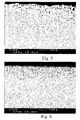
- Fig 7 shows a scanning electron micrograph of the surface zone after decarburizing in a decarburizing atmosphere + heat treating in a neutral gas atmosphere + an additional heat treating in a carburizing atmosphere.
- Fig 8 shows a scanning electron micrograph of the surface zone after decarburizing in a decarburizing atmosphere + heat treating in a neutral gas atmosphere + an additional heat treating in a carburizing atmosphere + another additional heat treating in a neutral gas atmosphere + further another additional heat treating in a carburizing atmosphere.
- the images are from the cross-sections of cutting tool inserts.
- cemented carbide bodies are first decarburized by heating them to a temperature between 900 and 1290 °C (-heat treating step No 1), preferably between 1000 and 1250 °C, in a decarburizing atmosphere such as H 2 +H 2 O, or H 2 +CO 2 .
- the time for the treatment is between 1 and 10 h.
- the degree of decarburization depends on temperature, time and oxygen content in the decarburizing gas, and also on the furnace type.
- the decarburization treatment results in a ⁇ 100 ⁇ m thick surface zone containing essentially eta phase, or W + Co 7 W 6 , or W + eta phase, or eta phase + WC.
- W-Co-gamma phase grades also the gamma phase will be present within the decarburized zone besides the eta phase.
- Other phases which may be found in the surface zone are oxides of the elements present in the cemented carbide bodies.
- WC-Co grades WO 3 and CoWO 4 phases may also be present in the surface zone.
- Decarburization at temperatures between 950 and 1050°C gives more even thickness of the decarburized zones along the entire surface of the treated bodies whereas decarburization at temperatures between 1200 and 1290 °C gives thicker decarburized zones at the edges and corners than at the plane faces of the bodies.
- the bodies are heat-treated in a neutral gas atmosphere or vacuum in heat treating step No 2, to retransform the eta phase or other phases formed during decarburization to a Co enriched WC+Co comprising surface zone.
- This heat treatment is performed at a temperature between 1350 and 1450 °C for 10 min to 10 h, preferably for 30 min to 3 h.
- the selection of suitable temperature and holding time is influenced by the carbon content and degree of decarburization of the heat treated bodies. Bodies subjected to stronger decarburization need longer holding time and/or higher heat treating temperature than bodies subjected to weak decarburization.
- the heat treating step No 2 can be performed at one temperature with one holding time, or at more than one temperature and more than one holding time. For example, one part of this heat treatment can be performed at lower temperature such as 1375 °C with holding time 1.5 h and another part at higher temperature such as 1450 °C with a holding time of 3 h.
- the shape of the WC grains can be unchanged or changed to platelet form.
- WC platelets with or without specific orientation.
- the formation of the WC platelets is easier in cemented carbide bodies without grain growth inhibitors.
- a surface monolayer of WC platelets will form oriented perpendicularly to the surface of the body.
- WC platelets embedded in the surface zone without specific orientation.
- the temperature in heat treating step No 2 is selected between 1250 and 1340 °C, and the bodies subjected to low or intermediate degree of decarburization, there will be formed in certain embodiments a surface comprising WC platelets with increased grain size compared to the nominal WC grain size.
- the WC platelets will have a specific orientation with the major part of the platelets being oriented perpendicularly to the surface of the body.
- the major part of the WC grains is present in the form of a surface monolayer of WC platelets.
- the WC platelets can be surrounded by eta phase at short holding time ⁇ 0.1-0.5 h or by high Co contents (Co-enrichment) at intermediate holding time 0.5-2 h, or by very low Co-contents (Co-depletion) at long holding time 2-4 h.
- the heat treatment should be performed in neutral gas atmosphere or vacuum at temperatures higher than 1350 °C (heat treating step No 2), with holding time selected so that no eta phase is present after the heat treatment.
- Such surface zones will in certain embodiments comprise WC grains with increased WC grain size with or without platelet form. The WC grains with increased grain size will be present within the whole surface zone and not only at the surface.
- the eta phase is transformed to a WC+Co surface zone with or without increased WC grain size and with Co enrichment, using carbon from the inner parts of cemented carbide bodies.
- the maximum Co content within the surface zone is obtained just after completed transformation of the eta phase to WC+Co.
- Prolonged holding time and/or increased heat treating temperature after formation of the WC+Co zone enriched in Co will result within the surface zone of certain embodiments in decreased Co content.
- the Co content after prolonged heat treating holding time/ heat treating step No 2A, and/or additional treatment in increased heat treating temperature/ heat treating step No 2B, both steps in neutral atmosphere will result in Co contents approximately the same, or even lower than the nominal Co content.
- the heat treating step No 2B can be performed at more than one heat treating temperature and more than one holding time.
- WC grain growth will occur. Limited WC grain growth occurs also within the rest of the cemented carbide body, but due to higher Co content within the surface zone compared to the rest of the body the WC growth will be much faster within the surface zone than in the rest of the body.
- the selection of holding time and temperature depends on the degree of decarburization. All eta phase within the surface zone is transformed to WC+Co.
- the surface zone shall be 5-100 ⁇ m, preferably 5-30 ⁇ m, thick.
- the thickness of the surface zone at the cutting tool edges is the same as that at the plane surfaces, or it is ⁇ 5 times, preferably ⁇ 2 times, thicker at the cutting edges. No or small difference in thickness is obtained for cemented carbide bodies with weak decarburization at low temperatures or weak to medium decarburization and bodies with increased Co contents - more than 8 weight-%. In certain embodiments with thick zones obtained after heavy decarburization it is suitable to remove the surface zone at the clearance side of the cutting tool and thus obtain cutting tools with equal thickness on the rake face. Another possibility to decrease the thickness of the surface zone at the cutting edges is to perform the edge rounding process of the cutting tool after the heat treating process and not before as usual.
- the thickness of the surface zone at the cutting edges between 10% to 90% of the thickness at the plane surface, or in certain embodiments it can be completely removed at the outermost parts of the cutting edge within 10 to 100 ⁇ m long distance measured at the cross section of the cutting edge.
- the difference in thickness of the surface zone at the cutting edges and the plane surfaces is due to larger decarburization of the edges than the plane surfaces obtained due to the decarburizing treatment.
- the surface zone is present only at the cutting edges to a distance of 1 mm or preferably up to 0.5 mm from the outermost part of the edge.
- the surface roughness R a is ⁇ 10 ⁇ m, preferably ⁇ 5 ⁇ m.
- the Co-content within the surface zone may be at least 10% higher, or between +10% and -40% of the nominal Co-content.
- the size and shape of the WC grains may be changed or remain unchanged.
- the WC grain size within the surface zone can be increased by at least by 20%, preferably by more than 30%, or be more or less unchanged compared to the nominal WC grain size within the rest of the body.
- the increase of the WC grain size takes place mainly in WC-Co bodies without grain growth inhibitors. Larger increase is obtained for cemented carbide grades with relatively high carbon content close to the saturation point compared to grades with low carbon contents close to the formation of eta phase.
- Within the surface zones with increased WC grain size a WC grain size gradient is observed. The grain size increases from the inner parts of the surface zone towards the outer parts of the surface zone. Both types of the surface zones with or without increase in WC grain size and with Co enrichment are suitable in cutting operations with large demands on toughness.
- step No 2 Another possibility how to reduce or adjust the Co content is to use after step No 2 further additional heat treating steps where at least one of heat treating steps is performed in reducing atmosphere- containing CH 4 +H 2 gas mixture. Reduction in the Co content is obtained in further additional heat treating steps (heat treating steps No 2A, 2B, 3, 4 and 5) after heat treating steps No 1 and 2.
- the heat treating step No 3 is performed in a carburizing atmosphere such as CH 4 +H 2 , within the temperature range 1200-1370 °C and the time 0.1-2 h.
- the heat treating step No 4 is performed in a neutral gas atmosphere or vacuum at temperatures between 1350 and 1450 °C and holding time between 0.1 and 2 h.
- the heat treating step No 5 is performed in a carburizing atmosphere such as CH 4 +H 2 , within the temperature range 1200-1370 °C and the time 0.1-2 h.
- Bodies according to the invention are coated with wear resistant coatings using known coating methods.
- the method of the present invention can be applied to WC-Co bodies with or without addition of ⁇ 3 weight-%, preferably ⁇ 2.5 weight-% grain growth inhibitors such as Cr, Ti, Ta, Nb and V, with 3-12, preferably 5-12, weight-% binder phase, with average WC grain size of 0.3-3 ⁇ m, preferably 0.5-1.7 ⁇ m, with a carbon content not exceeding carbon saturation. Preferably no eta phase is present in the bodies prior to the decarburizing treatment.
- the method of the present invention can also be applied to WC-Co-gamma phase bodies, comprising totally up to 10 weight-% of at least one of following elements Ti, Ta, Nb, Zr, Hf.
- the binder phase is preferably Co but it can comprise or consist of other elements such as Fe and Ni or mixtures thereof.
- intermediate to strong decarburization is performed at a temperature between 1000 °C and 1250 °C (heat treating step No 1), holding time 2-10 h, in H 2 +H 2 O with dew point between 0°C and -30°C, or H 2 +CO 2 atmosphere containing 10-20 % CO 2 followed by a heat treatment performed in a neutral gas atmosphere or vacuum between 1360 and 1410 °C (heat treating step no 2) for 0.5 to 5 h.
- the surface zone is 5-100 ⁇ m thick, preferably 10-30 ⁇ m thick, with an average Co content at least 10%, preferably 30%, higher than the nominal Co content.
- an additional intermediate zone between the surface zone and the inner parts of the body.
- This intermediate zone has about the same thickness or is up to 200% thicker than the surface zone and comprises WC phase with grain size 10-30% smaller than that within the cemented carbide body.
- the Co content within this zone may be within 10% variation essentially the same as the nominal Co content outside the surface zone or between 10% and 30% lower than the nominal Co content.
- An intermediate zone with decreased WC grain size may be present in cemented carbide bodies with Co contents below 8 weight-%, without grain growth inhibitors and subjected to a strong decarburization treatment. This intermediate zone is absent in bodies with grain growth inhibitors and/or Co contents above 8 weight-%.
- the shape of the major part of the WC grains is essentially unchanged or partly changed to platelet form.
- the WC grain size and the amount of the WC platelets increase within the surface zone towards the surface of the body. Grain growth also takes place in WC-Co bodies containing small amounts of weak grain growth inhibitors. However, no WC grain growth is observed in bodies containing VC.
- Cemented carbide according to this embodiment is most suitable in cutting operations with large demands on mechanical toughness in cutting operations using heavy interrupted cuts in steel or cast iron without coolant.
- the second preferred embodiment is obtained using bodies from the first preferred embodiment being furthermore heat treated in the three additional heat treating steps No 3, 4 and 5.
- the Co content within surface zone is adjusted to within 20% variation of the nominal Co content.
- the Co content within the surface zone is adjusted to within 10% variation of the nominal Co content and after heat treating steps No 1, 2, 3, 4 and 5 the Co content within the surface zone is adjusted to between -20 and -40% of the nominal Co content.
- the average WC grain size within the surface zone is within 10 % variation the same or up to 30% larger as in the first preferred embodiment.
- Cemented carbide according to this embodiment is most suitable in toughness demanding cutting operations with increased amounts of thermal cycling leading to the creation of thermal cracks and thermally induced flaking, occurring during interrupted cutting of stainless steel with coolant.
- the third preferred embodiment is obtained in WC-Co based bodies containing conventional amounts of grain growth inhibitors after weak to intermediate decarburization heat treatment (heat treating step No 1).
- the decarburizing treatment is performed either at relatively low temperatures such as 950-1000 °C, for up to 10 h in a H 2 +H 2 O atmosphere with a dew point between +15 and +25 °C or at relatively high temperatures such as 1250 °C for 1-2 h and in a H 2 +H 2 O atmosphere with a dew point between -20 and -30 °C.
- Thin surface zones are obtained after such decarburizing treatment with a thickness of up to 10 ⁇ m.
- the heat treating step in neutral gas atmosphere (heat treating step No 2) such as Ar or vacuum is performed at 1350-1410 °C, for 20 min to 3 h.
- the surface zone has a Co content at least 10%, preferably 30%, higher than the nominal Co content.
- the average WC grain size is unchanged or up to 20% larger than the average WC grain size within the rest of the cemented carbide body.
- the thickness of the surface zone is between 5 and 20 ⁇ m, preferably 5 and 10 ⁇ m.
- Cemented carbide according to this embodiment is most suitable in cutting operations with large demands on toughness using cutting tool inserts with relatively small edge radius.
- Cemented carbide cutting tool inserts CNMG120412 made in the conventional way were heat treated according to the invention according to Table 1.
- Table 2 shows the resulting surface zone.
- the inserts were further coated and tested in cutting tests against untreated inserts with the same coating with results according to Table 2.
Landscapes
- Chemical & Material Sciences (AREA)
- Engineering & Computer Science (AREA)
- Materials Engineering (AREA)
- Mechanical Engineering (AREA)
- Metallurgy (AREA)
- Organic Chemistry (AREA)
- Chemical Kinetics & Catalysis (AREA)
- Cutting Tools, Boring Holders, And Turrets (AREA)
- Powder Metallurgy (AREA)
- Chemical Vapour Deposition (AREA)
- Physical Vapour Deposition (AREA)
Applications Claiming Priority (2)
| Application Number | Priority Date | Filing Date | Title |
|---|---|---|---|
| SE0004290A SE522730C2 (sv) | 2000-11-23 | 2000-11-23 | Metod för tillverkning av en belagd hårdmetallkropp avsedd för skärande bearbetning |
| EP01997573.9A EP1339892B1 (de) | 2000-11-23 | 2001-11-23 | Verfahren zur herstellung von beschichteten hartmetall-schneidwerkzeugen |
Related Parent Applications (5)
| Application Number | Title | Priority Date | Filing Date |
|---|---|---|---|
| PCT/SE2001/002600 Previously-Filed-Application WO2002042515A1 (en) | 2000-11-23 | 2001-11-23 | Method of making coated cemented carbide cutting tools |
| EP01997573.9A Division EP1339892B1 (de) | 2000-11-23 | 2001-11-23 | Verfahren zur herstellung von beschichteten hartmetall-schneidwerkzeugen |
| EP01997573.9A Division-Into EP1339892B1 (de) | 2000-11-23 | 2001-11-23 | Verfahren zur herstellung von beschichteten hartmetall-schneidwerkzeugen |
| WOPCT/SE01/02600 Previously-Filed-Application | 2001-11-23 | ||
| EP01997573.9 Division | 2001-11-23 |
Publications (3)
| Publication Number | Publication Date |
|---|---|
| EP2522760A2 true EP2522760A2 (de) | 2012-11-14 |
| EP2522760A3 EP2522760A3 (de) | 2013-06-05 |
| EP2522760B1 EP2522760B1 (de) | 2016-08-31 |
Family
ID=20281930
Family Applications (2)
| Application Number | Title | Priority Date | Filing Date |
|---|---|---|---|
| EP01997573.9A Expired - Lifetime EP1339892B1 (de) | 2000-11-23 | 2001-11-23 | Verfahren zur herstellung von beschichteten hartmetall-schneidwerkzeugen |
| EP12151563.9A Expired - Lifetime EP2522760B1 (de) | 2000-11-23 | 2001-11-23 | Beschichtetes Hartmetall |
Family Applications Before (1)
| Application Number | Title | Priority Date | Filing Date |
|---|---|---|---|
| EP01997573.9A Expired - Lifetime EP1339892B1 (de) | 2000-11-23 | 2001-11-23 | Verfahren zur herstellung von beschichteten hartmetall-schneidwerkzeugen |
Country Status (5)
| Country | Link |
|---|---|
| US (3) | US7150897B2 (de) |
| EP (2) | EP1339892B1 (de) |
| JP (1) | JP4153301B2 (de) |
| SE (1) | SE522730C2 (de) |
| WO (1) | WO2002042515A1 (de) |
Cited By (1)
| Publication number | Priority date | Publication date | Assignee | Title |
|---|---|---|---|---|
| CN104498684A (zh) * | 2015-01-19 | 2015-04-08 | 四川科力特硬质合金股份有限公司 | 一种硬质合金在真空烧结炉中脱碳的方法 |
Families Citing this family (27)
| Publication number | Priority date | Publication date | Assignee | Title |
|---|---|---|---|---|
| US9428822B2 (en) | 2004-04-28 | 2016-08-30 | Baker Hughes Incorporated | Earth-boring tools and components thereof including material having hard phase in a metallic binder, and metallic binder compositions for use in forming such tools and components |
| SE528427C2 (sv) * | 2004-07-09 | 2006-11-07 | Seco Tools Ab | Ett belagt skär för metallbearbetning och sätt att tillverka detta |
| SE528109C2 (sv) * | 2004-07-12 | 2006-09-05 | Sandvik Intellectual Property | Fasningsskär, speciellt för fasfräsning av stålplåt för oljerör, samt sätt att tillverka detsamma |
| SE529590C2 (sv) * | 2005-06-27 | 2007-09-25 | Sandvik Intellectual Property | Finkorniga sintrade hårdmetaller innehållande en gradientzon |
| SE529015C2 (sv) * | 2005-09-09 | 2007-04-10 | Sandvik Intellectual Property | PVD-belagt skärverktygsskär tillverkat av hårdmetall |
| US20090029132A1 (en) * | 2005-11-17 | 2009-01-29 | Boehlerit Gmbh & Co. Kg., | Coated hard metal member |
| SE530517C2 (sv) * | 2006-08-28 | 2008-06-24 | Sandvik Intellectual Property | Belagt hårdmetallskär, sätt att tillverka detta samt dess användning för fräsning av hårda Fe-baserade legeringar > 45 HRC |
| US9132567B2 (en) | 2007-03-23 | 2015-09-15 | Dayton Progress Corporation | Tools with a thermo-mechanically modified working region and methods of forming such tools |
| US8968495B2 (en) | 2007-03-23 | 2015-03-03 | Dayton Progress Corporation | Methods of thermo-mechanically processing tool steel and tools made from thermo-mechanically processed tool steels |
| US20090169594A1 (en) * | 2007-09-18 | 2009-07-02 | Stefania Polizu | Carbon nanotube-based fibers, uses thereof and process for making same |
| EP2184122A1 (de) * | 2008-11-11 | 2010-05-12 | Sandvik Intellectual Property AB | Zementierter Carbidkörper und Verfahren |
| GB0903322D0 (en) * | 2009-02-27 | 2009-04-22 | Element Six Holding Gmbh | Hard-metal substrate with graded microstructure |
| US8327958B2 (en) | 2009-03-31 | 2012-12-11 | Diamond Innovations, Inc. | Abrasive compact of superhard material and chromium and cutting element including same |
| US8614935B2 (en) * | 2009-12-16 | 2013-12-24 | Oracle America, Inc. | Data storage system and method for calibrating same |
| FR2954197B1 (fr) * | 2009-12-22 | 2012-04-20 | Eads Europ Aeronautic Defence | Foret a goujures droites |
| JP2011177830A (ja) * | 2010-03-01 | 2011-09-15 | Mitsubishi Materials Corp | 表面被覆wc基超硬合金製切削工具 |
| EP2571646A4 (de) * | 2010-05-20 | 2016-10-05 | Baker Hughes Inc | Verfahren zur formung mindestens eines teils eines erdbohrwerkzeugs |
| CA2799906A1 (en) | 2010-05-20 | 2011-11-24 | Baker Hughes Incorporated | Methods of forming at least a portion of earth-boring tools, and articles formed by such methods |
| CA2799911A1 (en) * | 2010-05-20 | 2011-11-24 | Baker Hughes Incorporated | Methods of forming at least a portion of earth-boring tools, and articles formed by such methods |
| JP5561607B2 (ja) * | 2010-09-15 | 2014-07-30 | 三菱マテリアル株式会社 | 表面被覆wc基超硬合金製インサート |
| JP5851826B2 (ja) * | 2010-12-24 | 2016-02-03 | 三菱日立ツール株式会社 | 高温下での耐塑性変形性に優れる切削工具用wc基超硬合金および被覆切削工具ならびにこれらの製造方法 |
| WO2012146311A1 (en) | 2011-04-29 | 2012-11-01 | Istanbul Teknik Universitesi | Method for modifying and alloying surfaces of wc based hard metal structures |
| JP5815709B2 (ja) * | 2011-06-27 | 2015-11-17 | 京セラ株式会社 | 硬質合金および切削工具 |
| JP6375636B2 (ja) * | 2014-02-14 | 2018-08-22 | 新日鐵住金株式会社 | 超硬工具用基材及び超硬工具、並びに超硬工具用基材及び超硬工具の製造方法 |
| CN108677136A (zh) * | 2018-05-28 | 2018-10-19 | 株洲硬质合金集团有限公司 | 一种消除硬质合金脱碳缺陷的方法 |
| GB201900988D0 (en) * | 2019-01-24 | 2019-03-13 | Hyperion Materials & Tech Sweden Ab | Lightweight cemented carbide |
| CN110629095A (zh) * | 2019-08-09 | 2019-12-31 | 株洲美特优硬质合金有限公司 | 梯度硬质合金复合棒材及其制备方法 |
Citations (7)
| Publication number | Priority date | Publication date | Assignee | Title |
|---|---|---|---|---|
| US4830886A (en) | 1988-03-07 | 1989-05-16 | Gte Valenite Corporation | Process for making cutting insert with titanium carbide coating |
| US4830930A (en) | 1987-01-05 | 1989-05-16 | Toshiba Tungaloy Co., Ltd. | Surface-refined sintered alloy body and method for making the same |
| EP0560212A1 (de) | 1992-03-05 | 1993-09-15 | Sumitomo Electric Industries, Limited | Beschichteter Hartmetallkörper |
| US5665431A (en) | 1991-09-03 | 1997-09-09 | Valenite Inc. | Titanium carbonitride coated stratified substrate and cutting inserts made from the same |
| WO1998035071A1 (en) | 1997-02-05 | 1998-08-13 | Cemecon-Ceramic Metal Coatings-Dr.-Ing. Antonius Leyendecker Gmbh | Hard material coating of a cemented carbide or carbide containing cermet substrate |
| WO1999031292A1 (en) | 1997-12-18 | 1999-06-24 | Sandvik Ab (Publ) | Coated cemented carbide cutting tool and method of coating it with diamond |
| WO2000031314A1 (en) | 1998-11-20 | 2000-06-02 | Kennametal Inc. | Diamond coated cutting tools and method of manufacture |
Family Cites Families (8)
| Publication number | Priority date | Publication date | Assignee | Title |
|---|---|---|---|---|
| SE453202B (sv) * | 1986-05-12 | 1988-01-18 | Sandvik Ab | Sinterkropp for skerande bearbetning |
| SE456428B (sv) * | 1986-05-12 | 1988-10-03 | Santrade Ltd | Hardmetallkropp for bergborrning med bindefasgradient och sett att framstella densamma |
| SE500050C2 (sv) * | 1991-02-18 | 1994-03-28 | Sandvik Ab | Hårdmetallkropp för slitande mineralavverkning och sätt att framställa denna |
| ATE195766T1 (de) * | 1991-04-10 | 2000-09-15 | Sandvik Ab | Verfahren zur herstellung zementierter karbidartikel |
| SE514283C2 (sv) * | 1995-04-12 | 2001-02-05 | Sandvik Ab | Belagt hårmetallskär med bindefasadanrikad ytzon samt sätt för dess tillverkning |
| SE513740C2 (sv) * | 1995-12-22 | 2000-10-30 | Sandvik Ab | Slitstark hårmetallkropp främst för användning vid bergborrning och mineralbrytning |
| SE517474C2 (sv) * | 1996-10-11 | 2002-06-11 | Sandvik Ab | Sätt att tillverka hårdmetall med bindefasanrikad ytzon |
| SE516071C2 (sv) * | 1999-04-26 | 2001-11-12 | Sandvik Ab | Hårdmetallskär belagt med en slitstark beläggning |
-
2000
- 2000-11-23 SE SE0004290A patent/SE522730C2/sv unknown
-
2001
- 2001-11-23 US US10/432,436 patent/US7150897B2/en not_active Expired - Fee Related
- 2001-11-23 EP EP01997573.9A patent/EP1339892B1/de not_active Expired - Lifetime
- 2001-11-23 JP JP2002545215A patent/JP4153301B2/ja not_active Expired - Fee Related
- 2001-11-23 WO PCT/SE2001/002600 patent/WO2002042515A1/en not_active Ceased
- 2001-11-23 EP EP12151563.9A patent/EP2522760B1/de not_active Expired - Lifetime
-
2006
- 2006-09-27 US US11/527,530 patent/US7384689B2/en not_active Expired - Fee Related
-
2008
- 2008-03-27 US US12/078,140 patent/US7700186B2/en not_active Expired - Fee Related
Patent Citations (7)
| Publication number | Priority date | Publication date | Assignee | Title |
|---|---|---|---|---|
| US4830930A (en) | 1987-01-05 | 1989-05-16 | Toshiba Tungaloy Co., Ltd. | Surface-refined sintered alloy body and method for making the same |
| US4830886A (en) | 1988-03-07 | 1989-05-16 | Gte Valenite Corporation | Process for making cutting insert with titanium carbide coating |
| US5665431A (en) | 1991-09-03 | 1997-09-09 | Valenite Inc. | Titanium carbonitride coated stratified substrate and cutting inserts made from the same |
| EP0560212A1 (de) | 1992-03-05 | 1993-09-15 | Sumitomo Electric Industries, Limited | Beschichteter Hartmetallkörper |
| WO1998035071A1 (en) | 1997-02-05 | 1998-08-13 | Cemecon-Ceramic Metal Coatings-Dr.-Ing. Antonius Leyendecker Gmbh | Hard material coating of a cemented carbide or carbide containing cermet substrate |
| WO1999031292A1 (en) | 1997-12-18 | 1999-06-24 | Sandvik Ab (Publ) | Coated cemented carbide cutting tool and method of coating it with diamond |
| WO2000031314A1 (en) | 1998-11-20 | 2000-06-02 | Kennametal Inc. | Diamond coated cutting tools and method of manufacture |
Cited By (2)
| Publication number | Priority date | Publication date | Assignee | Title |
|---|---|---|---|---|
| CN104498684A (zh) * | 2015-01-19 | 2015-04-08 | 四川科力特硬质合金股份有限公司 | 一种硬质合金在真空烧结炉中脱碳的方法 |
| CN104498684B (zh) * | 2015-01-19 | 2017-01-25 | 四川科力特硬质合金股份有限公司 | 一种硬质合金在真空烧结炉中脱碳的方法 |
Also Published As
| Publication number | Publication date |
|---|---|
| US7150897B2 (en) | 2006-12-19 |
| JP4153301B2 (ja) | 2008-09-24 |
| SE522730C2 (sv) | 2004-03-02 |
| US20040091749A1 (en) | 2004-05-13 |
| SE0004290D0 (sv) | 2000-11-23 |
| SE0004290L (sv) | 2002-05-24 |
| JP2004514790A (ja) | 2004-05-20 |
| US20080187778A1 (en) | 2008-08-07 |
| US20070020477A1 (en) | 2007-01-25 |
| US7700186B2 (en) | 2010-04-20 |
| EP2522760B1 (de) | 2016-08-31 |
| EP1339892B1 (de) | 2015-11-11 |
| WO2002042515A1 (en) | 2002-05-30 |
| US7384689B2 (en) | 2008-06-10 |
| EP1339892A1 (de) | 2003-09-03 |
| EP2522760A3 (de) | 2013-06-05 |
Similar Documents
| Publication | Publication Date | Title |
|---|---|---|
| EP2522760B1 (de) | Beschichtetes Hartmetall | |
| US6299992B1 (en) | Method of making cemented carbide with binder phase enriched surface zone | |
| US5729823A (en) | Cemented carbide with binder phase enriched surface zone | |
| EP0682580B1 (de) | Langbohrer mit titancarbonitriden schneideinsätzen | |
| EP0603143B1 (de) | Carbid-Metall-Verbundstoff mit einer in der Oberfläche angereicheten Binderphase | |
| US4843039A (en) | Sintered body for chip forming machining | |
| EP0438916B1 (de) | Beschichteter Hartmetallkörper und Verfahren zu seiner Herstellung | |
| EP0627016B1 (de) | Zementiertes karbid mit binderphase angereicherter oberflächenzone | |
| EP0727510B1 (de) | Verbesserter, mit Alumina beschichteter Sinterkarbidkörper | |
| USRE35538E (en) | Sintered body for chip forming machine | |
| EP0685572A2 (de) | Beschichtete Klinge aus Hart metallegierung | |
| JP2008238393A (ja) | 改良型のアルミナで被覆された等級の工具インサート | |
| US7794830B2 (en) | Sintered cemented carbides using vanadium as gradient former | |
| JPH0693473A (ja) | 被覆超硬合金 | |
| IL107976A (en) | Glued carbide with the help of a surface enriched in the phase of a binder and a method for its production |
Legal Events
| Date | Code | Title | Description |
|---|---|---|---|
| PUAI | Public reference made under article 153(3) epc to a published international application that has entered the european phase |
Free format text: ORIGINAL CODE: 0009012 |
|
| AC | Divisional application: reference to earlier application |
Ref document number: 1339892 Country of ref document: EP Kind code of ref document: P |
|
| AK | Designated contracting states |
Kind code of ref document: A2 Designated state(s): AT BE CH CY DE DK ES FI FR GB GR IE IT LI LU MC NL PT SE TR |
|
| PUAL | Search report despatched |
Free format text: ORIGINAL CODE: 0009013 |
|
| AK | Designated contracting states |
Kind code of ref document: A3 Designated state(s): AT BE CH CY DE DK ES FI FR GB GR IE IT LI LU MC NL PT SE TR |
|
| RIC1 | Information provided on ipc code assigned before grant |
Ipc: C23C 8/20 20060101AFI20130429BHEP Ipc: C23C 8/80 20060101ALI20130429BHEP Ipc: C23C 30/00 20060101ALI20130429BHEP Ipc: C22C 29/08 20060101ALI20130429BHEP |
|
| 17P | Request for examination filed |
Effective date: 20131205 |
|
| RBV | Designated contracting states (corrected) |
Designated state(s): AT BE CH CY DE DK ES FI FR GB GR IE IT LI LU MC NL PT SE TR |
|
| RIC1 | Information provided on ipc code assigned before grant |
Ipc: C23C 8/20 20060101AFI20160324BHEP Ipc: C22C 29/08 20060101ALI20160324BHEP Ipc: C23C 30/00 20060101ALI20160324BHEP Ipc: C23C 8/80 20060101ALI20160324BHEP |
|
| GRAP | Despatch of communication of intention to grant a patent |
Free format text: ORIGINAL CODE: EPIDOSNIGR1 |
|
| INTG | Intention to grant announced |
Effective date: 20160509 |
|
| GRAS | Grant fee paid |
Free format text: ORIGINAL CODE: EPIDOSNIGR3 |
|
| GRAA | (expected) grant |
Free format text: ORIGINAL CODE: 0009210 |
|
| AC | Divisional application: reference to earlier application |
Ref document number: 1339892 Country of ref document: EP Kind code of ref document: P |
|
| AK | Designated contracting states |
Kind code of ref document: B1 Designated state(s): AT BE CH CY DE DK ES FI FR GB GR IE IT LI LU MC NL PT SE TR |
|
| REG | Reference to a national code |
Ref country code: CH Ref legal event code: EP Ref country code: GB Ref legal event code: FG4D |
|
| REG | Reference to a national code |
Ref country code: IE Ref legal event code: FG4D |
|
| REG | Reference to a national code |
Ref country code: DE Ref legal event code: R096 Ref document number: 60150098 Country of ref document: DE |
|
| REG | Reference to a national code |
Ref country code: AT Ref legal event code: REF Ref document number: 825046 Country of ref document: AT Kind code of ref document: T Effective date: 20161015 |
|
| REG | Reference to a national code |
Ref country code: NL Ref legal event code: MP Effective date: 20160831 |
|
| REG | Reference to a national code |
Ref country code: AT Ref legal event code: MK05 Ref document number: 825046 Country of ref document: AT Kind code of ref document: T Effective date: 20160831 |
|
| PG25 | Lapsed in a contracting state [announced via postgrant information from national office to epo] |
Ref country code: FI Free format text: LAPSE BECAUSE OF FAILURE TO SUBMIT A TRANSLATION OF THE DESCRIPTION OR TO PAY THE FEE WITHIN THE PRESCRIBED TIME-LIMIT Effective date: 20160831 |
|
| PGFP | Annual fee paid to national office [announced via postgrant information from national office to epo] |
Ref country code: DE Payment date: 20161116 Year of fee payment: 16 |
|
| PG25 | Lapsed in a contracting state [announced via postgrant information from national office to epo] |
Ref country code: NL Free format text: LAPSE BECAUSE OF FAILURE TO SUBMIT A TRANSLATION OF THE DESCRIPTION OR TO PAY THE FEE WITHIN THE PRESCRIBED TIME-LIMIT Effective date: 20160831 Ref country code: ES Free format text: LAPSE BECAUSE OF FAILURE TO SUBMIT A TRANSLATION OF THE DESCRIPTION OR TO PAY THE FEE WITHIN THE PRESCRIBED TIME-LIMIT Effective date: 20160831 Ref country code: GR Free format text: LAPSE BECAUSE OF FAILURE TO SUBMIT A TRANSLATION OF THE DESCRIPTION OR TO PAY THE FEE WITHIN THE PRESCRIBED TIME-LIMIT Effective date: 20161201 Ref country code: AT Free format text: LAPSE BECAUSE OF FAILURE TO SUBMIT A TRANSLATION OF THE DESCRIPTION OR TO PAY THE FEE WITHIN THE PRESCRIBED TIME-LIMIT Effective date: 20160831 Ref country code: BE Free format text: LAPSE BECAUSE OF NON-PAYMENT OF DUE FEES Effective date: 20161130 Ref country code: SE Free format text: LAPSE BECAUSE OF FAILURE TO SUBMIT A TRANSLATION OF THE DESCRIPTION OR TO PAY THE FEE WITHIN THE PRESCRIBED TIME-LIMIT Effective date: 20160831 |
|
| PG25 | Lapsed in a contracting state [announced via postgrant information from national office to epo] |
Ref country code: DK Free format text: LAPSE BECAUSE OF FAILURE TO SUBMIT A TRANSLATION OF THE DESCRIPTION OR TO PAY THE FEE WITHIN THE PRESCRIBED TIME-LIMIT Effective date: 20160831 Ref country code: PT Free format text: LAPSE BECAUSE OF FAILURE TO SUBMIT A TRANSLATION OF THE DESCRIPTION OR TO PAY THE FEE WITHIN THE PRESCRIBED TIME-LIMIT Effective date: 20170102 Ref country code: BE Free format text: LAPSE BECAUSE OF FAILURE TO SUBMIT A TRANSLATION OF THE DESCRIPTION OR TO PAY THE FEE WITHIN THE PRESCRIBED TIME-LIMIT Effective date: 20160831 |
|
| REG | Reference to a national code |
Ref country code: DE Ref legal event code: R097 Ref document number: 60150098 Country of ref document: DE |
|
| PG25 | Lapsed in a contracting state [announced via postgrant information from national office to epo] |
Ref country code: IT Free format text: LAPSE BECAUSE OF FAILURE TO SUBMIT A TRANSLATION OF THE DESCRIPTION OR TO PAY THE FEE WITHIN THE PRESCRIBED TIME-LIMIT Effective date: 20160831 |
|
| REG | Reference to a national code |
Ref country code: CH Ref legal event code: PL |
|
| PLBE | No opposition filed within time limit |
Free format text: ORIGINAL CODE: 0009261 |
|
| STAA | Information on the status of an ep patent application or granted ep patent |
Free format text: STATUS: NO OPPOSITION FILED WITHIN TIME LIMIT |
|
| GBPC | Gb: european patent ceased through non-payment of renewal fee |
Effective date: 20161130 |
|
| PG25 | Lapsed in a contracting state [announced via postgrant information from national office to epo] |
Ref country code: CH Free format text: LAPSE BECAUSE OF NON-PAYMENT OF DUE FEES Effective date: 20161130 Ref country code: LI Free format text: LAPSE BECAUSE OF NON-PAYMENT OF DUE FEES Effective date: 20161130 |
|
| 26N | No opposition filed |
Effective date: 20170601 |
|
| REG | Reference to a national code |
Ref country code: IE Ref legal event code: MM4A |
|
| REG | Reference to a national code |
Ref country code: FR Ref legal event code: ST Effective date: 20170731 |
|
| PG25 | Lapsed in a contracting state [announced via postgrant information from national office to epo] |
Ref country code: LU Free format text: LAPSE BECAUSE OF NON-PAYMENT OF DUE FEES Effective date: 20161130 |
|
| PG25 | Lapsed in a contracting state [announced via postgrant information from national office to epo] |
Ref country code: FR Free format text: LAPSE BECAUSE OF NON-PAYMENT OF DUE FEES Effective date: 20161130 |
|
| PG25 | Lapsed in a contracting state [announced via postgrant information from national office to epo] |
Ref country code: IE Free format text: LAPSE BECAUSE OF NON-PAYMENT OF DUE FEES Effective date: 20161123 Ref country code: GB Free format text: LAPSE BECAUSE OF NON-PAYMENT OF DUE FEES Effective date: 20161130 |
|
| PG25 | Lapsed in a contracting state [announced via postgrant information from national office to epo] |
Ref country code: CY Free format text: LAPSE BECAUSE OF FAILURE TO SUBMIT A TRANSLATION OF THE DESCRIPTION OR TO PAY THE FEE WITHIN THE PRESCRIBED TIME-LIMIT Effective date: 20160831 |
|
| REG | Reference to a national code |
Ref country code: DE Ref legal event code: R119 Ref document number: 60150098 Country of ref document: DE |
|
| PG25 | Lapsed in a contracting state [announced via postgrant information from national office to epo] |
Ref country code: TR Free format text: LAPSE BECAUSE OF FAILURE TO SUBMIT A TRANSLATION OF THE DESCRIPTION OR TO PAY THE FEE WITHIN THE PRESCRIBED TIME-LIMIT Effective date: 20160831 Ref country code: MC Free format text: LAPSE BECAUSE OF FAILURE TO SUBMIT A TRANSLATION OF THE DESCRIPTION OR TO PAY THE FEE WITHIN THE PRESCRIBED TIME-LIMIT Effective date: 20160831 |
|
| PG25 | Lapsed in a contracting state [announced via postgrant information from national office to epo] |
Ref country code: DE Free format text: LAPSE BECAUSE OF NON-PAYMENT OF DUE FEES Effective date: 20180602 |