EP2520003B1 - Solarladegerät zum aufladen eines akkumulators - Google Patents
Solarladegerät zum aufladen eines akkumulators Download PDFInfo
- Publication number
- EP2520003B1 EP2520003B1 EP10840577.0A EP10840577A EP2520003B1 EP 2520003 B1 EP2520003 B1 EP 2520003B1 EP 10840577 A EP10840577 A EP 10840577A EP 2520003 B1 EP2520003 B1 EP 2520003B1
- Authority
- EP
- European Patent Office
- Prior art keywords
- unit
- power battery
- solar charger
- charging
- switch
- Prior art date
- Legal status (The legal status is an assumption and is not a legal conclusion. Google has not performed a legal analysis and makes no representation as to the accuracy of the status listed.)
- Active
Links
Images
Classifications
-
- H—ELECTRICITY
- H02—GENERATION; CONVERSION OR DISTRIBUTION OF ELECTRIC POWER
- H02J—ELECTRIC POWER NETWORKS; CIRCUIT ARRANGEMENTS OR SYSTEMS FOR SUPPLYING OR DISTRIBUTING ELECTRIC POWER; SYSTEMS FOR STORING ELECTRIC ENERGY
- H02J7/00—Circuit arrangements for charging or discharging batteries or for supplying loads from batteries
- H02J7/34—Parallel operation in networks using both storage and other DC sources, e.g. providing buffering
- H02J7/35—Parallel operation in networks using both storage and other DC sources, e.g. providing buffering with light sensitive cells
-
- H—ELECTRICITY
- H01—ELECTRIC ELEMENTS
- H01M—PROCESSES OR MEANS, e.g. BATTERIES, FOR THE DIRECT CONVERSION OF CHEMICAL ENERGY INTO ELECTRICAL ENERGY
- H01M10/00—Secondary cells; Manufacture thereof
- H01M10/42—Methods or arrangements for servicing or maintenance of secondary cells or secondary half-cells
- H01M10/46—Accumulators structurally combined with charging apparatus
- H01M10/465—Accumulators structurally combined with charging apparatus with solar battery as charging system
-
- H—ELECTRICITY
- H10—SEMICONDUCTOR DEVICES; ELECTRIC SOLID-STATE DEVICES NOT OTHERWISE PROVIDED FOR
- H10F—INORGANIC SEMICONDUCTOR DEVICES SENSITIVE TO INFRARED RADIATION, LIGHT, ELECTROMAGNETIC RADIATION OF SHORTER WAVELENGTH OR CORPUSCULAR RADIATION
- H10F19/00—Integrated devices, or assemblies of multiple devices, comprising at least one photovoltaic cell covered by group H10F10/00, e.g. photovoltaic modules
-
- Y—GENERAL TAGGING OF NEW TECHNOLOGICAL DEVELOPMENTS; GENERAL TAGGING OF CROSS-SECTIONAL TECHNOLOGIES SPANNING OVER SEVERAL SECTIONS OF THE IPC; TECHNICAL SUBJECTS COVERED BY FORMER USPC CROSS-REFERENCE ART COLLECTIONS [XRACs] AND DIGESTS
- Y02—TECHNOLOGIES OR APPLICATIONS FOR MITIGATION OR ADAPTATION AGAINST CLIMATE CHANGE
- Y02E—REDUCTION OF GREENHOUSE GAS [GHG] EMISSIONS, RELATED TO ENERGY GENERATION, TRANSMISSION OR DISTRIBUTION
- Y02E10/00—Energy generation through renewable energy sources
- Y02E10/50—Photovoltaic [PV] energy
-
- Y—GENERAL TAGGING OF NEW TECHNOLOGICAL DEVELOPMENTS; GENERAL TAGGING OF CROSS-SECTIONAL TECHNOLOGIES SPANNING OVER SEVERAL SECTIONS OF THE IPC; TECHNICAL SUBJECTS COVERED BY FORMER USPC CROSS-REFERENCE ART COLLECTIONS [XRACs] AND DIGESTS
- Y02—TECHNOLOGIES OR APPLICATIONS FOR MITIGATION OR ADAPTATION AGAINST CLIMATE CHANGE
- Y02E—REDUCTION OF GREENHOUSE GAS [GHG] EMISSIONS, RELATED TO ENERGY GENERATION, TRANSMISSION OR DISTRIBUTION
- Y02E60/00—Enabling technologies; Technologies with a potential or indirect contribution to GHG emissions mitigation
- Y02E60/10—Energy storage using batteries
Definitions
- the present disclosure relates to an electric vehicle, more particularly, to a solar charger for charging a power battery.
- US 2004/066173 A1 cf. the preamble of claim 1 discloses an active switch with a photo transistor controlling a MOSFET switch to connect or disconnect a solar array to a battery.
- CN 201 023 493 Y discloses a signal for a railway crossing with a solar battery panel and a battery. Depending on the external light intensity two switches are operated to either activate an LED display or to load the battery.
- An embodiments of the present disclosure provides a solar charger for charging a power battery, comprising: a photo-sensitive unit configured to detect light intensity; a charging unit configured to receive a voltage transformed from solar energy and to boost the voltage so as to provide the voltage to the power battery; a switch unit coupled between the charging unit and the power battery and configured to disconnect the charging unit from the power battery of connect the charging unit with the power battery; and a control unit coupled to the photo-sensitive unit, the switch unit and the charging unit respectively, and configured to switch on the charging unit and the switch unit when the light intensity is higher than a first predetermined value so as to charge the power battery; wherein the control unit is configured to periodically compare a current light intensity detected by the photo-sensitive unit with the first predetermined value, to switch off the charging unit and the switch unit if the current light intensity is lower than the first predetermined value, and to switch on the charging unit and the switch unit if the current light intensity is higher than the first predetermined value.
- the charging unit may boost the voltage that is inputted into the charging unit and transformed from the solar energy, so as to provide the voltage to the power battery under the control of the control unit, thereby realizing the aim to charge the power battery
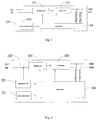
- the solar charger 100 comprises a photo-sensitive unit 101, a switch unit 102, a charging unit 103 and a control unit 104.
- the control unit 104 is coupled to the photo-sensitive unit 101, the switch unit 102 and the charging unit 103 respectively.
- the photo-sensitive unit 101 is configured to detect the light intensity and to send the light intensity to the control unit 104.
- the photo-sensitive unit 101 may be a photo-sensitive resistance or other photo-sensitive components.
- the switch unit 102 is coupled between the charging unit 103 and the power battery and configured to disconnect the charging unit 103 from the power battery or connect the charging unit 103 with the power battery under the control of the control unit 104.
- the switch unit 102 may be a relay.
- the control unit 104 may cause the relay to be switched on so as to allow the charging unit 103 to charge the power battery under the control of the control unit 104.
- the control unit 104 may cause the relay to be switched off so as to disconnect the charging unit 103 from the power battery, thus the solar charger 100 may not charge the power battery.
- the relay has resistance properties of " excellent insulation when the relay is switched off and has resistance properties of low conduction when the relay is switched on. Therefore, the relay may effectively disconnect the charging unit 103 from the power battery when the relay is switched off, to avoid misoperation of the control unit 104 when a voltage imputted into the charging unit 103 is sampled at the output voltage sampling line (corresponding to the voltage , sampling + arid the voltage sapling - in Fig. 1 ) when the charging of the power battery is stropped. In addition, the charging performance of the solar charger 100 may not be influenced when the relay is switched on.
- the charging unit 103 is configured to receive a voltage that is inputted into the charging unit 103 and transformed from solar energy and to boost the voltage so as to provide the voltage to the power battery under the control of the control unit 104 when the switch unit 102 is switched on.
- the device for transforming the solar energy into the voltage may be a solar battery board.
- the charging unit 103 may boost the voltage (for example, 320V) outputted from the solar battery board to the power battery voltage (for example, 570V) which is higher than the voltage (for example, 320V) outputted from the solar battery board, which may realize the aim to charge the power battery.
- the control unit 104 is configured to receive the light intensity provided by the photo-sensitive unit 101. When the light intensity is higher than a first predetermined value (for example, a value of no less than 50 lux), the control unit 104 switches on the charging unit 103 and the switch unit 102, thus the charging unit 103 may charge the power battery.
- the control unit 104 monitors the voltage of the power battery, and switches off the charging unit 103 and the switch unit 102 when the voltage of the power battery reaches a saturation value (for example, 570 V). It should be understood that, here, 570 V is just an example.
- the saturation value of the power battery may be different values according to the capacities of element cells in the power battery and the number of the element cells.
- the control unit 104 may monitor the power battery voltage by the voltage samplings at the output end of the solar charger 100 in Fig. 1 (that is, the voltage sampling + and the voltage sampling - in Fig. 1 ).
- Fig. 1 As shown in Fig. 1 , "in+” and “in-” are a positive input terminal and a negative input terminal of the solar charger 100 respectively, and “out+” and “out-” are a positive output terminal and a negative output terminal of the solar charger 100 respectively.
- the positive input terminal and the negative input terminal of the solar charger 100 may be coupled to a solar harvesting device (such as the solar battery board) via a service switch (not shown), and the positive output terminal and the negative output terminal may be coupled to the power battery via another service switch (not shown).
- the charging unit 103 may boost the voltage that is inputted into the charging unit 103 and transformed from the solar energy so as to provide the voltage to the power battery under the control of the control unit 104, thereby realizing the aim to charge the power battery.
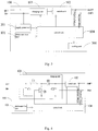
- the solar charger 100 further comprises a power battery unit 201 coupled to the control unit 104, and configured to receive and steady the voltage that is inputted into the charging unit 103 and transformed from the solar energy so as to power the control unit 104; and when the voltage transformed from the solar energy reaches a second predetermined value, the control unit 104 starts to work.
- the control unit 104 may not work, so the solar charger 100 may not work.
- the solar charger 100 of the present disclosure may start to work, thus having the functions of automatic starting and closing.
- the second predetermined value may be no less than 12 V, such as 80 V. As is known, the value is just an example and the second predetermined value may be different values according to the actual conditions. Typically, only when the voltage inputted into the charging unit 103 is higher than a predetermined value (for example, 100 V), the control unit 104 may switch on the charging unit 103. Therefore, in a preferred embodiment of the present disclosure, the second predetermined value is less than a minimum voltage that is inputted into the charging unit 103 when the control unit 104 switches on the charging unit 103.
- control unit 104 is configured to periodically (for example, at intervals of 30 minutes) switch on the switch unit 102 so as to detect the current voltage of the power battery after the voltage of the power battery reaches a saturation value, and to switch on the charging unit 103 and the switch unit 102 so as to charge the power battery when the current voltage of the power battery is lower than the saturation value (for example, 570 V) and the light intensity detected by the photo-sensitive unit is higher than the first predetermined value.
- saturation value for example, 570 V
- the periodic time T for periodically switching on the switch unit 102 may be determined according to the capacity and the energy dissipation of the power battery, typically, may be about 10 minutes to about 50 minutes, that is, the control unit 104 switches on the switch unit 102 to detect the current voltage of the power battery at intervals of T.
- control unit 104 is further configured to periodically (for example, every 3 minutes) compare the current light intensity detected by the photo-sensitive unit 101 with the first predetermined value, to switch off the charging unit 103 and the switch unit 102 if the current light intensity is lower than the first predetermined value, and to switch on the charging unit 103 and the switch unit 102 if the current light intensity is higher than the first predetermined value, thus ensuring that the power battery is not charged at low light intensity.
- the periodic time for periodically comparing the light intensity with the first predetermined value may be about 0.5 minutes to about 10 minutes.
- control unit 104 is further configured to communicate with an external control device (such as a battery manager or a display device) and to control the charging unit 103 and the switch unit 102 according to instructions from the external control device.
- the control unit 104 may switch off the charging unit 103 and the switch unit 102 if the control unit 104 receives instructions of fast or slow charging before the solar charger 100 charges the power battery, as a result, the power battery may be charged via a mains supply.
- the control unit 104 may switch off the charging unit 103 and the switch unit 102, as a result, the power battery may be charged via the mains supply. Therefore, the solar charger 100 of the present disclosure may satisfy various needs for charging, for example, fast charging or slow charting.
- the solar charger 100 may further comprise a cooling unit 301 coupled to the control unit 104.
- the cooling unit 301 is configured to cool the solar charger 100 when a temperature of the solar charger 100 detected by the control unit 104 reaches a third predetermined value.
- the third predetermined value is about 40 °C to about 100°C, such as 85 °C .
- the temperature of the solar charger 100 may be detected by a temperature sensor, and because the charging unit 103 is the main energy transforming component, the temperature near the charging unit 103 is preferably detected.
- the switch unit 102 is coupled to the positive and negative output terminals of the solar charger 100. It should be understood that, actually, the switch unit 102 may be coupled to one of the positive and negative output terminals (such as the positive output terminal) of the solar charger 100.
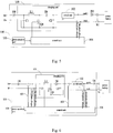
- the charging unit 103 may comprise a first capacitor C1 having a first end coupled to the positive input terminal of the solar charger 100 and a second end coupled to the negative input terminal of the solar charger 100; a first inductance L1 having a first end coupled to the positive input terminal of the solar charger 100; a first diode D1 having a positive end coupled to a second end of the first inductance L1; a IVIOSFET Q1 having a gate electrode coupled to the control unit 104, a drain electrode coupled to the second end of the first inductance L1, and a source electrode coupled to the second end of the first capacitor C1; and a second capacitor C2 having a first end coupled to a negative end of the first diode D1 and a second end coupled to the second end of the first capacitor C1.
- the negative end of the diode D1 is coupled to one end of the switch unit 102, the other end of the switch unit 102 is coupled to the positive output terminal of the solar charger 100, and the negative output terminal of the solar charger 100 may be coupled to the negative input terminal thereof, which may ensure that the solar charger 100 will transform from high voltage to high voltage.
- the diode between the source electrode and the drain electrode of the MOSFET Q1 is a built-in diode.
- the solar charger 100 may further comprise a second diode D2 having a positive end coupled to the positive input terminal of the solar charger 100 and a negative end coupled to a positive input of the charging unit 103, which may avoid the damage to the solar charger 100 when the positive and negative input terminals of the solar charger 100 are inversely connected.
- the solar charger 100 may further comprise a third diode D3 having a positive end coupled to an output end of the switch unit 102 and a negative end coupled to the power battery, which may avoid the influence of the voltage of the power battery on the output voltage sampling of the solar charger 100 in the charging and non-charging periods
- the solar charger 100 may further comprise a first current sensor 601 configured to detect an input current at the positive input end of the charging unit 103 and to provide the input current detected by the first current sensor 601 to the control unit 104, so that the control unit 104 may adjust the duty ratio of the MOSFET Q1 according to the input current detected by the first current sensor 601 and the voltage inputted into the charging unit 103; thus adjusting the output loading power and then adjusting the output power of the solar harvesting device (not shown) that provides an input voltage to the charging unit 103. Therefore, the solar harvesting device may reach the maximum output power.
- a first current sensor 601 configured to detect an input current at the positive input end of the charging unit 103 and to provide the input current detected by the first current sensor 601 to the control unit 104, so that the control unit 104 may adjust the duty ratio of the MOSFET Q1 according to the input current detected by the first current sensor 601 and the voltage inputted into the charging unit 103; thus adjusting the output loading power and then adjusting the output power of the solar
- the solar charger 100 further comprises a second current sensor 602 configured to detect an output current at an output end of the charging unit 103 and to provide the output current detected by the second current sensor 602 to the control unit 104.
- the control unit 104 may calculate the output loading power and the charging efficiency of the solar charger 100.
- the switch unit S1 in the aforementioned Fig. 5 and Fig. 6 is a service switch configured to facilitate the disassembling of the solar charger 100
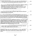
- the preferred charging flow of the solar charger 100 may be interpreted as follows in conjunction with the flow chart shown in Fig. 7 :
- the charging flow shown in Fig. 7 is just a preferred flow Some steps in the flow may be omitted or changed according to the actual conditions. For example, after step 577, if the solar charger 100 of the present disclosure receives the instruction of fast charging or slow charging, the process of fast charging or slow charging may be performed first.
- the power battery of an electric bus or vehicle may be charged during the driving process, thus not only strengthening the endurance performance of the vehicle, but also retarding the damage to the power battery under large current, protecting the performance of the power battery and prolonging the life of the power battery.
- the solar charger may operate correspondingly according to different instructions from the external control devices, the operating state of the solar charger may be flexibly controlled.
Landscapes
- Engineering & Computer Science (AREA)
- Life Sciences & Earth Sciences (AREA)
- Sustainable Development (AREA)
- Sustainable Energy (AREA)
- Manufacturing & Machinery (AREA)
- Chemical & Material Sciences (AREA)
- Chemical Kinetics & Catalysis (AREA)
- Electrochemistry (AREA)
- General Chemical & Material Sciences (AREA)
- Power Engineering (AREA)
- Charge And Discharge Circuits For Batteries Or The Like (AREA)
- Secondary Cells (AREA)
Claims (14)
- Solarladegerät (100) zum Aufladen eines Akkumulators, umfassend:eine photoempfindliche Einheit (101), die dazu ausgelegt ist, eine Lichtintensität zu erfassen,eine Aufladeeinheit (103), die dazu ausgelegt ist, eine aus Solarenergie umgewandelte Spannung zu empfangen;eine Schaltereinheit (102), die zwischen der Aufladeeinheit (103) und dem Akkumulator gekoppelt ist und dazu ausgelegt ist, die Aufladeeinheit (103) von dem Akkumulator zu trennen oder die Aufladeeinheit (103) mit dem Akkumulator zu verbinden; undeine Steuereinheit (104), die entsprechend mit der photoempfindlichen Einheit (101), der Schaltereinheit (102) und der Aufladeeinheit (103) gekoppelt ist und dazu ausgelegt ist, die Schaltereinheit (102) einzuschalten, wenn die Lichtintensität höher ist als ein erster vorgegebener Wert, um den Akkumulator aufzuladen,dadurch gekennzeichnet, dassdie Aufladeeinheit (103) dazu ausgelegt ist, die Spannung zu verstärken, um dem Akkumulator die Spannung bereitzustellen;die Steuereinheit (104) dazu ausgelegt ist, die Aufladeeinheit (103) einzuschalten, wenn die Lichtintensität höher ist als ein erster vorgegebener Wert, um den Akkumulator aufzuladen; unddie Steuereinheit (104) dazu ausgelegt ist, periodisch eine aktuelle Lichtintensität, die durch die photoempfindliche Einheit (101) erfasst wird, mit dem ersten vorgegebenen Wert zu vergleichen, um die Aufladeeinheit (103) und die Schaltereinheit (102) auszuschalten, wenn die aktuelle Lichtintensität niedriger ist als der erste vorgegebene Wert, und die Aufladeeinheit (103) und die Schaltereinheit (102) einzuschalten, wenn die aktuelle Lichtintensität höher ist als der erste vorgegebene Wert.
- Solarladegerät nach Anspruch 1, wobei die Steuereinheit (104) weiterhin dazu ausgelegt ist, während des Aufladens des Akkumulators die Spannung des Akkumulators zu überwachen und die Aufladeeinheit (103) und die Schaltereinheit (102) auszuschalten, wenn die Spannung des Akkumulators einen Sättigungswert erreicht.
- Solarladegerät nach Anspruch 1, weiterhin umfassend:eine Energieversorgungseinheit (201), die mit der Steuereinheit (104) gekoppelt ist und dazu ausgelegt ist, die aus der Solarenergie umgewandelte Spannung zu empfangen und zu stabilisieren, um die Steuereinheit (104) zu speisen,wobei die Steuereinheit (104) in Betrieb ist, wenn die aus der Solarenergie umgewandelte Spannung einen zweiten vorgegebenen Wert erreicht, wobei der zweite vorgegebene Wert vorzugsweise mindestens 12 V beträgt.
- Solarladegerät nach Anspruch 2, wobei die Steuereinheit (104) weiterhin dazu ausgelegt ist, periodisch die Schaltereinheit (102) einzuschalten, um eine aktuelle Spannung des Akkumulators zu erfassen, nachdem die Spannung des Akkumulators einen Sättigungswert erreicht, und die Aufladeeinheit (103) und die Schaltereinheit (102) einzuschalten, um den Akkumulator aufzuladen, wenn die aktuelle Spannung des Akkumulators niedriger ist als der Sättigungswert und die durch die photoempfindliche Einheit (101) erfasste Lichtintensität höher ist als der erste vorgegebene Wert.
- Solarladegerät nach Anspruch 4, wobei eine Periodenzeit zum periodischen Einschalten der Schaltereinheit (102) 10 bis 50 Minuten beträgt.
- Solarladegerät nach Anspruch 1, wobei eine Periodenzeit zum periodischen Vergleichen der Lichtintensität mit dem ersten vorgegebenen Wert 0,5 bis 10 Minuten beträgt.
- Solarladegerät nach Anspruch 6, wobei die Steuereinheit (104) weiterhin dazu ausgelegt ist, mit einer externen Steuervorrichtung zu kommunizieren und die Aufladeeinheit (103) und die Schaltereinheit (102) gemäß Befehlen von der externen Steuervorrichtung zu steuern.
- Solarladegerät nach Anspruch 7, wobei die Steuereinheit (104) weiterhin dazu ausgelegt ist, die Aufladeeinheit (103) und die Schaltereinheit (102) auszuschalten, wenn die Steuereinheit (104) Befehle zum schnellen oder langsamen Aufladen empfängt.
- Solarladegerät nach Anspruch 1, weiterhin umfassend:eine Kühleinheit (301), die mit der Steuereinheit (104) gekoppelt ist und dazu ausgelegt ist, das Solarladegerät (100) zu kühlen, wenn eine durch die Steuereinheit (104) erfasste Temperatur des Solarladegeräts (100) einen dritten vorgegebenen Wert erreicht, wobei der dritte vorgegebene Wert vorzugsweise 40°C bis 100°C beträgt.
- Solarladegerät nach Anspruch 1, wobei der erste vorgegebene Wert mindestens 50 Lux beträgt.
- Solarladegerät nach Anspruch 1, wobei die Aufladeeinheit (103) umfasst:einen ersten Kondensator (C1), der ein erstes Ende, das mit einem positiven Eingangsanschlusspunkt des Solarladegeräts (100) gekoppelt ist, und ein zweites Ende, das mit einem negativen Eingangsanschlusspunkt des Solarladegeräts (100) gekoppelt ist, aufweist;eine erste Induktivität (L1), die ein erstes Ende aufweist, das mit dem positiven Eingangsanschlusspunkt des Solarladegeräts (100) gekoppelt ist;eine erste Diode (D1), die ein positives Ende aufweist, das mit einem zweiten Ende der ersten Induktivität (L1) gekoppelt ist;einen MOSFET (Q1), der eine Gate-Elektrode, die mit der Steuereinheit (104) gekoppelt ist, eine Drain-Elektrode, die mit dem zweiten Ende der ersten Induktivität (L1) gekoppelt ist, und eine Source-Elektrode, die mit dem zweiten Ende des ersten Kondensators (C1) gekoppelt ist, aufweist; undeinen zweiten Kondensator (C2), der ein erstes Ende, das mit einem negativen Ende der ersten Diode (D1) gekoppelt ist, und ein zweites Ende, das mit dem zweiten Ende des ersten Kondensators (C1) gekoppelt ist, aufweist.
- Solarladegerät nach Anspruch 11, weiterhin umfassend:eine zweite Diode (D2), die ein positives Ende, das mit dem positiven Eingangsanschlusspunkt des Solarladegeräts (100) gekoppelt ist, und ein negatives Ende, das mit einem positiven Eingangsende der Aufladeeinheit (103) gekoppelt ist, aufweist, und optional eine dritte Diode (D3), die ein positives Ende, das mit einem Ausgangsende der Schaltereinheit (102) gekoppelt ist, und ein negatives Ende, das mit dem Akkumulator gekoppelt ist, aufweist.
- Solarladegerät nach Anspruch 11, weiterhin umfassend:einen ersten Stromsensor (601), der dazu ausgelegt ist, an dem positiven Eingangsende der Aufladeeinheit (103) einen Eingangsstrom zu erfassen, wobei die Steuereinheit (104) gemäß dem durch den ersten Stromsensor (601) erfassten Eingangsstrom ein Tastverhältnis des MOSFET einstellt.
- Solarladegerät nach Anspruch 13, weiterhin umfassend:einen zweiten Stromsensor (602), der dazu ausgelegt ist, an einem Ausgangsende der Aufladeeinheit (103) einen Ausgangsstrom zu erfassen, wobei die Steuereinheit (104) gemäß dem durch den zweiten Stromsensor (602) erfassten Ausgangsstrom einen Ladewirkungsgrad des Solarladegeräts (100) bestimmt.
Applications Claiming Priority (2)
| Application Number | Priority Date | Filing Date | Title |
|---|---|---|---|
| CN200910260754XA CN102118043B (zh) | 2009-12-31 | 2009-12-31 | 用于对动力电池充电的太阳能充电器 |
| PCT/CN2010/080423 WO2011079789A1 (en) | 2009-12-31 | 2010-12-29 | Solar charger for charging power battery |
Publications (3)
| Publication Number | Publication Date |
|---|---|
| EP2520003A1 EP2520003A1 (de) | 2012-11-07 |
| EP2520003A4 EP2520003A4 (de) | 2014-05-07 |
| EP2520003B1 true EP2520003B1 (de) | 2016-03-30 |
Family
ID=44216684
Family Applications (1)
| Application Number | Title | Priority Date | Filing Date |
|---|---|---|---|
| EP10840577.0A Active EP2520003B1 (de) | 2009-12-31 | 2010-12-29 | Solarladegerät zum aufladen eines akkumulators |
Country Status (4)
| Country | Link |
|---|---|
| US (1) | US10270282B2 (de) |
| EP (1) | EP2520003B1 (de) |
| CN (1) | CN102118043B (de) |
| WO (1) | WO2011079789A1 (de) |
Families Citing this family (25)
| Publication number | Priority date | Publication date | Assignee | Title |
|---|---|---|---|---|
| CN102118043B (zh) | 2009-12-31 | 2013-12-04 | 比亚迪股份有限公司 | 用于对动力电池充电的太阳能充电器 |
| JP2014217115A (ja) * | 2013-04-23 | 2014-11-17 | パナソニックインテレクチュアル プロパティ コーポレーション オブアメリカPanasonic Intellectual Property Corporation of America | 電子機器及び充電器 |
| WO2015079504A1 (ja) * | 2013-11-26 | 2015-06-04 | 三菱電機株式会社 | 直流電源装置、およびそれを備えた冷凍サイクル適用機器 |
| KR101481342B1 (ko) * | 2013-12-06 | 2015-01-09 | 현대자동차주식회사 | 고속 충전용 멀티미디어 단자 장치 및 이의 제어 방법 |
| CN105304962B (zh) * | 2014-07-31 | 2019-03-05 | 惠州市吉瑞科技有限公司 | 一种电子烟及其充电方法 |
| JP6112094B2 (ja) * | 2014-10-22 | 2017-04-12 | トヨタ自動車株式会社 | 全固体電池システム |
| KR102319981B1 (ko) * | 2014-11-27 | 2021-11-01 | 삼성전자주식회사 | 다중 에너지 자원을 이용한 충전 방법 및 장치 |
| DE102015000577A1 (de) * | 2015-01-16 | 2016-07-21 | Audi Ag | Verfahren zum Betrieb eines Kraftfahrzeugs mit einer Solareinrichtung und Kraftfahrzeug |
| JP6434337B2 (ja) * | 2015-02-24 | 2018-12-05 | 本田技研工業株式会社 | 太陽光発電の開始判定装置 |
| JP6396236B2 (ja) * | 2015-02-24 | 2018-09-26 | 本田技研工業株式会社 | 太陽光発電の電圧変換装置 |
| DE102015006608B4 (de) * | 2015-05-21 | 2018-11-15 | Audi Ag | Verfahren zum Betrieb einer Photovoltaikeinrichtung eines Kraftfahrzeugs und Kraftfahrzeug |
| CN104852440B (zh) * | 2015-06-10 | 2017-12-29 | 联想(北京)有限公司 | 一种充电电路及电子设备 |
| CN105450805A (zh) * | 2015-12-22 | 2016-03-30 | 太原工业学院 | 一种压电能及太阳能自供电手机 |
| DE102016201113A1 (de) * | 2016-01-26 | 2017-07-27 | Bender Gmbh & Co. Kg | Laststeuerung einer Ladestation für ein Elektrofahrzeug |
| CN105946595A (zh) * | 2016-04-29 | 2016-09-21 | 百度在线网络技术(北京)有限公司 | 无人驾驶车辆的自动智能续航方法和装置 |
| US10343538B2 (en) | 2017-04-06 | 2019-07-09 | Ford Global Technologies, Llc | Controlling charge levels of vehicle batteries based on battery charge states and vehicle operating modes |
| CN107579654A (zh) * | 2017-09-30 | 2018-01-12 | 广东威灵电机制造有限公司 | 电机电源电路及洗衣机 |
| CN108233518A (zh) * | 2018-01-15 | 2018-06-29 | 米亚索能光伏科技有限公司 | 太阳能电池充电控制方法及系统 |
| CN108988433B (zh) * | 2018-08-16 | 2022-03-01 | 四川长虹电器股份有限公司 | 一种太阳能照明控制器的充电自动检测电路 |
| US12283840B2 (en) * | 2020-06-02 | 2025-04-22 | Inergy Holdings, LLC | Portable solar battery charging |
| US11552484B2 (en) * | 2020-10-29 | 2023-01-10 | Deltran Operations Usa, Inc. | Systems and methods for operating a solar charger system for providing battery and circuit protection |
| US12007799B2 (en) * | 2021-10-12 | 2024-06-11 | Everactive, Inc. | Energy operating systems and related techniques |
| WO2025042415A1 (en) * | 2023-08-22 | 2025-02-27 | Xcharge Energy Usa Inc. | Device, method, and medium for charging |
| CN117067930A (zh) * | 2023-09-12 | 2023-11-17 | 深圳市华宝新能源股份有限公司 | 光伏充电系统及车辆 |
| KR20250062734A (ko) * | 2023-10-31 | 2025-05-08 | 주식회사 엘지에너지솔루션 | 배터리 관리 시스템 및 그 통신 관리 방법 |
Family Cites Families (116)
| Publication number | Priority date | Publication date | Assignee | Title |
|---|---|---|---|---|
| FR2061904A6 (de) * | 1969-10-01 | 1971-06-25 | Accumulateurs Fixes | |
| US3971454A (en) * | 1971-04-20 | 1976-07-27 | Waterbury Nelson J | System for generating electrical energy to supply power to propel vehicles |
| US4187123A (en) * | 1975-10-21 | 1980-02-05 | Diggs Richard E | Directionally controlled array of solar power units |
| US4311953A (en) * | 1976-08-17 | 1982-01-19 | Sharp Kabushiki Kaisha | Charger using one or more solar batteries |
| US4136309A (en) * | 1977-07-01 | 1979-01-23 | Galberth Robert L | Power output control circuit for solar-powered cathodic protection system |
| US4328456A (en) * | 1978-02-24 | 1982-05-04 | Canon Kabushiki Kaisha | Camera with solar batteries connected in series or parallel |
| US4249520A (en) * | 1978-12-26 | 1981-02-10 | Orillion Alfred G | Pyramidal energy collector system |
| US4238721A (en) * | 1979-02-06 | 1980-12-09 | The United States Of America As Represented By The United States Department Of Energy | System and method for charging electrochemical cells in series |
| US4243928A (en) * | 1979-05-29 | 1981-01-06 | Exxon Research & Engineering Co. | Voltage regulator for variant light intensity photovoltaic recharging of secondary batteries |
| US4333136A (en) * | 1979-11-26 | 1982-06-01 | Baker Richard H | Solar powered automatic turn-on control (SPA-TOC) unit and method |
| JPS5962927A (ja) * | 1982-10-01 | 1984-04-10 | Nippon Denso Co Ltd | 移動体用太陽電池パッケージ装置 |
| DE3316775A1 (de) * | 1983-05-07 | 1984-11-08 | Faber, Peter, Dr., 8757 Karlstein | Verbundsteuerung von photozellen zur anpassung an elektrische verbraucher oder akkumulatoren |
| US5303305A (en) * | 1986-04-18 | 1994-04-12 | Raimo Robert W | Solar powered hearing aid |
| US4873480A (en) * | 1988-08-03 | 1989-10-10 | Lafferty Donald L | Coupling network for improving conversion efficiency of photovoltaic power source |
| US5055763A (en) * | 1988-09-26 | 1991-10-08 | Eveready Battery Company, Inc. | Electronic battery charger device and method |
| US5221891A (en) * | 1989-07-31 | 1993-06-22 | Intermatic Incorporated | Control circuit for a solar-powered rechargeable power source and load |
| US5086267A (en) * | 1989-07-31 | 1992-02-04 | Intermatic Incorporated | Control circuit for a solar-powered rechargeable power source and load |
| US5041952A (en) * | 1989-07-31 | 1991-08-20 | Intermatic Incorporated | Control circuit for a solar-powered rechargeable power source and load |
| US5196781A (en) * | 1990-09-14 | 1993-03-23 | Weiss Instruments, Inc. | Method and apparatus for power control of solar powered display devices |
| US5210804A (en) * | 1991-03-18 | 1993-05-11 | Schmid Guenther W | Solar powered hearing aid and reenergizer case |
| US5293447A (en) * | 1992-06-02 | 1994-03-08 | The United States Of America As Represented By The Secretary Of Commerce | Photovoltaic solar water heating system |
| JPH06124731A (ja) * | 1992-08-31 | 1994-05-06 | Toshiba Corp | 外部バッテリ接続用アタッチメント、バッテリパック及びバッテリ識別制御方法 |
| US5719555A (en) * | 1993-06-24 | 1998-02-17 | Cart Watch, Inc. | Golf cart control and monitoring apparatus and system using digital signal modulation techniques |
| US5627737A (en) * | 1993-09-13 | 1997-05-06 | Sanyo Electric Co., Ltd. | Power inverter for use in system interconnection |
| US5869951A (en) * | 1994-10-26 | 1999-02-09 | Fuji Jukogyo Kabushiki Kaisha | Battery management system for electric vehicle |
| US5781013A (en) * | 1994-10-26 | 1998-07-14 | Fuji Jukogyo Kabushiki Kaisha | Battery management system for electric vehicle |
| JPH08149833A (ja) * | 1994-11-18 | 1996-06-07 | Sanyo Electric Co Ltd | 太陽電池発電装置の制御用電源回路及び保護回路 |
| US5670861A (en) * | 1995-01-17 | 1997-09-23 | Norvik Tractions Inc. | Battery energy monitoring circuits |
| US5615129A (en) * | 1995-02-21 | 1997-03-25 | General Signal Power Systems, Inc. | Method and apparatus for adaptive and corrective determination of battery run-time in uninterruptible power systems |
| US5686809A (en) * | 1995-05-12 | 1997-11-11 | Fuji Photo Film Co., Ltd. | Combination solar and external battery powered camera battery charger |
| US5656915A (en) * | 1995-08-28 | 1997-08-12 | Eaves; Stephen S. | Multicell battery pack bilateral power distribution unit with individual cell monitoring and control |
| KR100205229B1 (ko) * | 1996-05-15 | 1999-07-01 | 윤종용 | 태양전지 전원장치 |
| JPH10201268A (ja) * | 1997-01-16 | 1998-07-31 | Toyota Motor Corp | 冷却装置付太陽光発電システム |
| US6271642B1 (en) * | 1998-02-13 | 2001-08-07 | Johnson Controls Technology Company | Advanced battery controller with state of charge control |
| US6765363B2 (en) * | 1998-03-10 | 2004-07-20 | U.S. Microbattery, Inc. | Micro power supply with integrated charging capability |
| JP3744679B2 (ja) * | 1998-03-30 | 2006-02-15 | 三洋電機株式会社 | 太陽光発電装置 |
| US6204645B1 (en) * | 1998-09-11 | 2001-03-20 | Richard A. Cullen | Battery charging controller |
| KR100305854B1 (ko) * | 1999-07-08 | 2001-11-01 | 이계안 | 전기 자동차용 배터리 팩 충전 장치 및 방법 |
| US6891354B2 (en) * | 1999-07-15 | 2005-05-10 | Fazakas Andras | Method for detecting slow and small changes of electrical signals |
| US6700351B2 (en) * | 2000-02-18 | 2004-03-02 | Liebert Corporation | Modular uninterruptible power supply battery management |
| JP2001268815A (ja) * | 2000-03-17 | 2001-09-28 | Nippon Telegr & Teleph Corp <Ntt> | 充電回路 |
| DE10019889C1 (de) * | 2000-04-20 | 2001-09-27 | Webasto Vehicle Sys Int Gmbh | Solareinrichtung für ein Fahrzeug |
| US6476583B2 (en) * | 2000-07-21 | 2002-11-05 | Jomahip, Llc | Automatic battery charging system for a battery back-up DC power supply |
| JP2002112553A (ja) * | 2000-09-29 | 2002-04-12 | Canon Inc | 電力変換装置およびその制御方法、並びに、発電装置 |
| US6806415B2 (en) * | 2000-11-10 | 2004-10-19 | Canon Kabushiki Kaisha | Method for controlling a solar power generation system having a cooling mechanism |
| US6630622B2 (en) * | 2001-01-15 | 2003-10-07 | Annemarie Hvistendahl Konold | Combined solar electric power and liquid heat transfer collector panel |
| US6404163B1 (en) * | 2001-06-25 | 2002-06-11 | General Motors Corporation | Method and system for regulating a charge voltage delivered to a battery |
| US6867568B1 (en) * | 2001-08-13 | 2005-03-15 | John Olson | Battery finish charge device |
| US6815931B1 (en) * | 2002-05-31 | 2004-11-09 | John T. Wells | Marine charge source switching system |
| US7612283B2 (en) * | 2002-07-09 | 2009-11-03 | Canon Kabushiki Kaisha | Solar power generation apparatus and its manufacturing method |
| US6713989B1 (en) | 2002-10-07 | 2004-03-30 | Solarmate Corporation | Solarswitch |
| CN2599851Y (zh) * | 2002-10-18 | 2004-01-14 | 庄佳璋 | 太阳能脉冲式充电系统 |
| US6897423B2 (en) * | 2002-11-14 | 2005-05-24 | Michael H. Redler | Self-powered intermittent moving light tracking device and method |
| US6808450B2 (en) * | 2002-12-04 | 2004-10-26 | Christopher E. Snow | Solar powered heating and ventilation system for vehicle |
| TWI247469B (en) * | 2003-02-11 | 2006-01-11 | O2Micro Int Ltd | Power supply system, electronic device comprising the same, and method of ensuring safe operation of batteries in parallel |
| WO2004099791A2 (en) * | 2003-04-23 | 2004-11-18 | Powertron Eng'g Co., Ltd | Diagnosis for expected life of emergency power apparatus |
| US7269036B2 (en) * | 2003-05-12 | 2007-09-11 | Siemens Vdo Automotive Corporation | Method and apparatus for adjusting wakeup time in electrical power converter systems and transformer isolation |
| US7068017B2 (en) * | 2003-09-05 | 2006-06-27 | Daimlerchrysler Corporation | Optimization arrangement for direct electrical energy converters |
| US20050133082A1 (en) * | 2003-12-20 | 2005-06-23 | Konold Annemarie H. | Integrated solar energy roofing construction panel |
| US7967465B2 (en) * | 2004-02-13 | 2011-06-28 | Simon Nicholas Richmond | Light device |
| JP4217644B2 (ja) * | 2004-03-23 | 2009-02-04 | キヤノン株式会社 | 発電システム、発電システムの管理装置及び管理方法 |
| JP4160919B2 (ja) * | 2004-03-24 | 2008-10-08 | シャープ株式会社 | インバータ装置 |
| JP2005318751A (ja) * | 2004-04-30 | 2005-11-10 | Shin Kobe Electric Mach Co Ltd | 多直列電池制御システム |
| JP4092580B2 (ja) * | 2004-04-30 | 2008-05-28 | 新神戸電機株式会社 | 多直列電池制御システム |
| GB2416605A (en) * | 2004-07-26 | 2006-02-01 | Wolfson Ltd | Dual power bus for battery powered device |
| US20060118162A1 (en) * | 2004-12-06 | 2006-06-08 | Florida Atlantic University | Powering a vehicle and providing excess energy to an external device using photovoltaic cells |
| US8077052B2 (en) * | 2005-01-07 | 2011-12-13 | Simon Nicholas Richmond | Illuminated wind indicator |
| CN101128973B (zh) * | 2005-02-25 | 2010-05-19 | 三菱电机株式会社 | 电力转换装置 |
| US7433215B2 (en) * | 2005-04-07 | 2008-10-07 | Pv Powered, Inc. | Inverter startup algorithm |
| US7502241B2 (en) * | 2005-04-07 | 2009-03-10 | Pv Powered, Inc. | Inverter startup algorithm |
| ATE508479T1 (de) * | 2005-07-20 | 2011-05-15 | Ecosol Solar Technologies Inc | Photovoltaische stromausgabebenutzende einrichtung |
| US20070023078A1 (en) * | 2005-07-28 | 2007-02-01 | James Palladino | Mobile vehicle having solar cell arrays for providing supplemental electric power |
| WO2007025096A1 (en) * | 2005-08-24 | 2007-03-01 | Ward Thomas A | Hybrid vehicle with modular solar panel and battery charging system to supplement regenerative braking |
| CN100525007C (zh) * | 2006-01-13 | 2009-08-05 | 宇太光电科技股份有限公司 | 可携式装置的复合供电系统 |
| JP2007228753A (ja) * | 2006-02-24 | 2007-09-06 | Toyota Motor Corp | 電動車両 |
| JP5162737B2 (ja) * | 2006-05-17 | 2013-03-13 | 英弘精機株式会社 | 太陽電池の特性評価装置 |
| CN2927596Y (zh) * | 2006-06-23 | 2007-07-25 | 杭州大有科技发展有限公司 | 双路供电太阳能灯控制器 |
| US8055389B2 (en) * | 2006-09-01 | 2011-11-08 | Dig Corporation | Method and apparatus for controlling irrigation |
| US20080084645A1 (en) * | 2006-10-04 | 2008-04-10 | Ahmad Nemer Jr | Emergency solar power supply |
| US8004113B2 (en) * | 2006-10-06 | 2011-08-23 | Apple Inc. | Methods and apparatuses for operating devices with solar power |
| CN200990520Y (zh) * | 2006-11-23 | 2007-12-12 | 深圳市彩歌科技有限公司 | 太阳能多功能充电器 |
| WO2008064605A1 (fr) * | 2006-11-30 | 2008-06-05 | Beijing Hi-Tech Wealth Investment & Development Co., Ltd | Procédé, appareil et système permettant de fournir de l'énergie à l'aide de cellules photovoltaïques |
| TW200830687A (en) * | 2007-01-15 | 2008-07-16 | zhen-yue Fan | Control apparatus of solar power system |
| US20080238354A1 (en) * | 2007-03-29 | 2008-10-02 | Kinpo Electronics, Inc. | Solar energy charging device for computer |
| CN201023493Y (zh) * | 2007-04-29 | 2008-02-20 | 吉林飞天科技有限公司 | 太阳能车挡表示器 |
| EP1993186A1 (de) * | 2007-05-15 | 2008-11-19 | Chen-Yueh Fan | Solarenergiesystem |
| US8203069B2 (en) * | 2007-08-03 | 2012-06-19 | Advanced Energy Industries, Inc | System, method, and apparatus for coupling photovoltaic arrays |
| JP5152746B2 (ja) * | 2007-08-08 | 2013-02-27 | 本田技研工業株式会社 | 燃料電池電源装置 |
| US20090078300A1 (en) * | 2007-09-11 | 2009-03-26 | Efficient Solar Power System, Inc. | Distributed maximum power point tracking converter |
| US20090079385A1 (en) * | 2007-09-21 | 2009-03-26 | Msr Innovations Inc. | Solar powered battery charger using switch capacitor voltage converters |
| CA2737134C (en) * | 2007-10-15 | 2017-10-10 | Ampt, Llc | Systems for highly efficient solar power |
| US8018748B2 (en) * | 2007-11-14 | 2011-09-13 | General Electric Company | Method and system to convert direct current (DC) to alternating current (AC) using a photovoltaic inverter |
| CN201141544Y (zh) * | 2007-12-13 | 2008-10-29 | 上海市晋元高级中学 | 太阳能感应路灯 |
| PT103923B (pt) * | 2008-01-07 | 2011-04-04 | Utad Universidade De Tras Os Montes E Alto Douro | Método e dispositivo de medida de irradiância solar utilizando um painel fotovoltaico |
| US8933320B2 (en) * | 2008-01-18 | 2015-01-13 | Tenksolar, Inc. | Redundant electrical architecture for photovoltaic modules |
| US8264194B1 (en) * | 2008-05-28 | 2012-09-11 | Google Inc. | Power control for a low power display |
| CN101604851B (zh) * | 2008-06-13 | 2012-11-21 | 鸿富锦精密工业(深圳)有限公司 | 蓄电池lvd数值的监控系统及方法 |
| US8264195B2 (en) * | 2008-10-01 | 2012-09-11 | Paceco Corp. | Network topology for monitoring and controlling a solar panel array |
| US8054039B2 (en) * | 2008-12-19 | 2011-11-08 | GM Global Technology Operations LLC | System and method for charging a plug-in electric vehicle |
| US7952233B2 (en) * | 2008-12-31 | 2011-05-31 | Bradley Fixtures Corporation | Lavatory system |
| DE112010000733T5 (de) * | 2009-01-15 | 2012-12-27 | Fisker Automotive, Inc. | Solarenergiemanagement in einem Fahrzeug |
| JP5350067B2 (ja) * | 2009-04-28 | 2013-11-27 | 本田技研工業株式会社 | 電源システム |
| IT1395681B1 (it) * | 2009-05-28 | 2012-10-16 | Beghelli Spa | Modulo strutturale per la generazione fotovoltaica ad alta concentrazione |
| EP2441152A2 (de) * | 2009-06-08 | 2012-04-18 | Techtium Ltd. | Solarzellen-ladesteuerung |
| WO2011031930A2 (en) * | 2009-09-12 | 2011-03-17 | Fenix International, Inc. | Method and apparatus for charging a battery |
| US9466737B2 (en) * | 2009-10-19 | 2016-10-11 | Ampt, Llc | Solar panel string converter topology |
| CN102118043B (zh) | 2009-12-31 | 2013-12-04 | 比亚迪股份有限公司 | 用于对动力电池充电的太阳能充电器 |
| US8975783B2 (en) * | 2010-01-20 | 2015-03-10 | Draker, Inc. | Dual-loop dynamic fast-tracking MPPT control method, device, and system |
| WO2012014281A1 (ja) * | 2010-07-27 | 2012-02-02 | Takeda Harumi | 蓄電装置の充電制御方法および放電制御方法 |
| JP5895161B2 (ja) * | 2010-08-06 | 2016-03-30 | パナソニックIpマネジメント株式会社 | 電池並列処理回路及び電池システム |
| CN102447270B (zh) * | 2010-09-30 | 2014-01-01 | 比亚迪股份有限公司 | 车辆用太阳能供电控制系统及控制方法 |
| US20130193904A1 (en) * | 2011-10-03 | 2013-08-01 | earthCell, Inc. | Charging unit useful to transform a high plurality of Energy Storage Devices |
| US20130127392A1 (en) * | 2011-10-03 | 2013-05-23 | earthCell, Inc. | Systems and Methods for transformation and transportation of energy storage devices |
| US20130134785A1 (en) * | 2011-11-30 | 2013-05-30 | General Electric Company | Single stage power conversion system |
| JP5673633B2 (ja) * | 2012-06-01 | 2015-02-18 | 株式会社デンソー | 車載充電制御装置 |
| US9156359B2 (en) * | 2012-09-28 | 2015-10-13 | GM Global Technology Operations LLC | Methods and vehicle systems for selectively using energy obtained from a solar subsystem |
-
2009
- 2009-12-31 CN CN200910260754XA patent/CN102118043B/zh active Active
-
2010
- 2010-12-29 WO PCT/CN2010/080423 patent/WO2011079789A1/en not_active Ceased
- 2010-12-29 EP EP10840577.0A patent/EP2520003B1/de active Active
-
2012
- 2012-06-29 US US13/538,016 patent/US10270282B2/en active Active
Also Published As
| Publication number | Publication date |
|---|---|
| US20120299529A1 (en) | 2012-11-29 |
| EP2520003A4 (de) | 2014-05-07 |
| US10270282B2 (en) | 2019-04-23 |
| WO2011079789A1 (en) | 2011-07-07 |
| EP2520003A1 (de) | 2012-11-07 |
| CN102118043A (zh) | 2011-07-06 |
| CN102118043B (zh) | 2013-12-04 |
Similar Documents
| Publication | Publication Date | Title |
|---|---|---|
| EP2520003B1 (de) | Solarladegerät zum aufladen eines akkumulators | |
| CN102545291B (zh) | 太阳能蓄电系统及太阳能供电系统 | |
| JP2019047721A (ja) | 太陽光充電システム及びその制御方法 この出願は、2017年9月1日に中国特許局に出願された出願特許公開第201710780286.3号、「太陽光充電補助システム及び制御方法」である中国特許出願の優先権を主張し、その開示内容の全ては参照により本出願に組み込まれる。 | |
| CN1396689A (zh) | 电池组的充电率调整电路 | |
| WO2023273490A1 (zh) | 控制电路、电路板组件及电池并联系统 | |
| CN111146847A (zh) | 一种锂电池管理系统的充放电保护电路和锂电池管理系统 | |
| CN110103768A (zh) | 一种电动汽车自动补电方法与装置 | |
| CN113178927A (zh) | 一种自动调节充电模式的充电系统及方法 | |
| CN117021978A (zh) | 一种动力电池系统、电动汽车及控制方法 | |
| CN103683435A (zh) | 移动式电源的稳压稳频ups与智能充电一体化方法 | |
| WO2018155442A1 (ja) | 直流給電システム | |
| CN219339219U (zh) | 充放电系统和车辆 | |
| CN1622424A (zh) | 充电器 | |
| CN217984639U (zh) | 一种锂电池保护装置及系统 | |
| CN108233520A (zh) | 一种光伏发电储电装置 | |
| CN2689563Y (zh) | 智能移动电源 | |
| CN208589807U (zh) | 一种太阳能控制器及太阳能系统 | |
| WO2021104373A1 (zh) | 一种多电池切换控制电路、装置、系统及控制方法 | |
| CN213906337U (zh) | 一种户外摄像机电源控制系统 | |
| CN223414618U (zh) | 一种延长锂电应急照明放电时间的管理控制电路 | |
| CN221380592U (zh) | 一种用于锂电池bms的自断电保护电路 | |
| CN223744400U (zh) | 一种bms低压供电控制电路 | |
| CN116979659B (zh) | 一种钠离子电池及电动车辆 | |
| CN216290262U (zh) | 一种新能源车动力电池的充放电控制电路 | |
| CN113511108B (zh) | 控制电路、方法以及系统 |
Legal Events
| Date | Code | Title | Description |
|---|---|---|---|
| PUAI | Public reference made under article 153(3) epc to a published international application that has entered the european phase |
Free format text: ORIGINAL CODE: 0009012 |
|
| 17P | Request for examination filed |
Effective date: 20120720 |
|
| AK | Designated contracting states |
Kind code of ref document: A1 Designated state(s): AL AT BE BG CH CY CZ DE DK EE ES FI FR GB GR HR HU IE IS IT LI LT LU LV MC MK MT NL NO PL PT RO RS SE SI SK SM TR |
|
| DAX | Request for extension of the european patent (deleted) | ||
| A4 | Supplementary search report drawn up and despatched |
Effective date: 20140409 |
|
| RIC1 | Information provided on ipc code assigned before grant |
Ipc: H02J 7/00 20060101AFI20140403BHEP Ipc: H02J 7/35 20060101ALI20140403BHEP Ipc: H01M 10/44 20060101ALI20140403BHEP Ipc: H01M 10/46 20060101ALI20140403BHEP |
|
| GRAP | Despatch of communication of intention to grant a patent |
Free format text: ORIGINAL CODE: EPIDOSNIGR1 |
|
| INTG | Intention to grant announced |
Effective date: 20151111 |
|
| GRAS | Grant fee paid |
Free format text: ORIGINAL CODE: EPIDOSNIGR3 |
|
| GRAA | (expected) grant |
Free format text: ORIGINAL CODE: 0009210 |
|
| AK | Designated contracting states |
Kind code of ref document: B1 Designated state(s): AL AT BE BG CH CY CZ DE DK EE ES FI FR GB GR HR HU IE IS IT LI LT LU LV MC MK MT NL NO PL PT RO RS SE SI SK SM TR |
|
| REG | Reference to a national code |
Ref country code: GB Ref legal event code: FG4D |
|
| REG | Reference to a national code |
Ref country code: CH Ref legal event code: EP |
|
| REG | Reference to a national code |
Ref country code: AT Ref legal event code: REF Ref document number: 786327 Country of ref document: AT Kind code of ref document: T Effective date: 20160415 |
|
| REG | Reference to a national code |
Ref country code: IE Ref legal event code: FG4D |
|
| REG | Reference to a national code |
Ref country code: DE Ref legal event code: R096 Ref document number: 602010031923 Country of ref document: DE |
|
| REG | Reference to a national code |
Ref country code: LT Ref legal event code: MG4D |
|
| PG25 | Lapsed in a contracting state [announced via postgrant information from national office to epo] |
Ref country code: GR Free format text: LAPSE BECAUSE OF FAILURE TO SUBMIT A TRANSLATION OF THE DESCRIPTION OR TO PAY THE FEE WITHIN THE PRESCRIBED TIME-LIMIT Effective date: 20160701 Ref country code: FI Free format text: LAPSE BECAUSE OF FAILURE TO SUBMIT A TRANSLATION OF THE DESCRIPTION OR TO PAY THE FEE WITHIN THE PRESCRIBED TIME-LIMIT Effective date: 20160330 Ref country code: NO Free format text: LAPSE BECAUSE OF FAILURE TO SUBMIT A TRANSLATION OF THE DESCRIPTION OR TO PAY THE FEE WITHIN THE PRESCRIBED TIME-LIMIT Effective date: 20160630 Ref country code: HR Free format text: LAPSE BECAUSE OF FAILURE TO SUBMIT A TRANSLATION OF THE DESCRIPTION OR TO PAY THE FEE WITHIN THE PRESCRIBED TIME-LIMIT Effective date: 20160330 |
|
| REG | Reference to a national code |
Ref country code: NL Ref legal event code: MP Effective date: 20160330 |
|
| REG | Reference to a national code |
Ref country code: AT Ref legal event code: MK05 Ref document number: 786327 Country of ref document: AT Kind code of ref document: T Effective date: 20160330 |
|
| PG25 | Lapsed in a contracting state [announced via postgrant information from national office to epo] |
Ref country code: RS Free format text: LAPSE BECAUSE OF FAILURE TO SUBMIT A TRANSLATION OF THE DESCRIPTION OR TO PAY THE FEE WITHIN THE PRESCRIBED TIME-LIMIT Effective date: 20160330 Ref country code: LT Free format text: LAPSE BECAUSE OF FAILURE TO SUBMIT A TRANSLATION OF THE DESCRIPTION OR TO PAY THE FEE WITHIN THE PRESCRIBED TIME-LIMIT Effective date: 20160330 Ref country code: LV Free format text: LAPSE BECAUSE OF FAILURE TO SUBMIT A TRANSLATION OF THE DESCRIPTION OR TO PAY THE FEE WITHIN THE PRESCRIBED TIME-LIMIT Effective date: 20160330 Ref country code: SE Free format text: LAPSE BECAUSE OF FAILURE TO SUBMIT A TRANSLATION OF THE DESCRIPTION OR TO PAY THE FEE WITHIN THE PRESCRIBED TIME-LIMIT Effective date: 20160330 |
|
| PG25 | Lapsed in a contracting state [announced via postgrant information from national office to epo] |
Ref country code: NL Free format text: LAPSE BECAUSE OF FAILURE TO SUBMIT A TRANSLATION OF THE DESCRIPTION OR TO PAY THE FEE WITHIN THE PRESCRIBED TIME-LIMIT Effective date: 20160330 |
|
| PG25 | Lapsed in a contracting state [announced via postgrant information from national office to epo] |
Ref country code: EE Free format text: LAPSE BECAUSE OF FAILURE TO SUBMIT A TRANSLATION OF THE DESCRIPTION OR TO PAY THE FEE WITHIN THE PRESCRIBED TIME-LIMIT Effective date: 20160330 Ref country code: PL Free format text: LAPSE BECAUSE OF FAILURE TO SUBMIT A TRANSLATION OF THE DESCRIPTION OR TO PAY THE FEE WITHIN THE PRESCRIBED TIME-LIMIT Effective date: 20160330 Ref country code: IS Free format text: LAPSE BECAUSE OF FAILURE TO SUBMIT A TRANSLATION OF THE DESCRIPTION OR TO PAY THE FEE WITHIN THE PRESCRIBED TIME-LIMIT Effective date: 20160730 |
|
| PG25 | Lapsed in a contracting state [announced via postgrant information from national office to epo] |
Ref country code: PT Free format text: LAPSE BECAUSE OF FAILURE TO SUBMIT A TRANSLATION OF THE DESCRIPTION OR TO PAY THE FEE WITHIN THE PRESCRIBED TIME-LIMIT Effective date: 20160801 Ref country code: ES Free format text: LAPSE BECAUSE OF FAILURE TO SUBMIT A TRANSLATION OF THE DESCRIPTION OR TO PAY THE FEE WITHIN THE PRESCRIBED TIME-LIMIT Effective date: 20160330 Ref country code: RO Free format text: LAPSE BECAUSE OF FAILURE TO SUBMIT A TRANSLATION OF THE DESCRIPTION OR TO PAY THE FEE WITHIN THE PRESCRIBED TIME-LIMIT Effective date: 20160330 Ref country code: SK Free format text: LAPSE BECAUSE OF FAILURE TO SUBMIT A TRANSLATION OF THE DESCRIPTION OR TO PAY THE FEE WITHIN THE PRESCRIBED TIME-LIMIT Effective date: 20160330 Ref country code: CZ Free format text: LAPSE BECAUSE OF FAILURE TO SUBMIT A TRANSLATION OF THE DESCRIPTION OR TO PAY THE FEE WITHIN THE PRESCRIBED TIME-LIMIT Effective date: 20160330 Ref country code: SM Free format text: LAPSE BECAUSE OF FAILURE TO SUBMIT A TRANSLATION OF THE DESCRIPTION OR TO PAY THE FEE WITHIN THE PRESCRIBED TIME-LIMIT Effective date: 20160330 Ref country code: AT Free format text: LAPSE BECAUSE OF FAILURE TO SUBMIT A TRANSLATION OF THE DESCRIPTION OR TO PAY THE FEE WITHIN THE PRESCRIBED TIME-LIMIT Effective date: 20160330 |
|
| REG | Reference to a national code |
Ref country code: FR Ref legal event code: PLFP Year of fee payment: 7 |
|
| PG25 | Lapsed in a contracting state [announced via postgrant information from national office to epo] |
Ref country code: BE Free format text: LAPSE BECAUSE OF FAILURE TO SUBMIT A TRANSLATION OF THE DESCRIPTION OR TO PAY THE FEE WITHIN THE PRESCRIBED TIME-LIMIT Effective date: 20160330 Ref country code: IT Free format text: LAPSE BECAUSE OF FAILURE TO SUBMIT A TRANSLATION OF THE DESCRIPTION OR TO PAY THE FEE WITHIN THE PRESCRIBED TIME-LIMIT Effective date: 20160330 |
|
| REG | Reference to a national code |
Ref country code: DE Ref legal event code: R097 Ref document number: 602010031923 Country of ref document: DE |
|
| PG25 | Lapsed in a contracting state [announced via postgrant information from national office to epo] |
Ref country code: DK Free format text: LAPSE BECAUSE OF FAILURE TO SUBMIT A TRANSLATION OF THE DESCRIPTION OR TO PAY THE FEE WITHIN THE PRESCRIBED TIME-LIMIT Effective date: 20160330 |
|
| PLBE | No opposition filed within time limit |
Free format text: ORIGINAL CODE: 0009261 |
|
| STAA | Information on the status of an ep patent application or granted ep patent |
Free format text: STATUS: NO OPPOSITION FILED WITHIN TIME LIMIT |
|
| 26N | No opposition filed |
Effective date: 20170103 |
|
| PG25 | Lapsed in a contracting state [announced via postgrant information from national office to epo] |
Ref country code: SI Free format text: LAPSE BECAUSE OF FAILURE TO SUBMIT A TRANSLATION OF THE DESCRIPTION OR TO PAY THE FEE WITHIN THE PRESCRIBED TIME-LIMIT Effective date: 20160330 |
|
| REG | Reference to a national code |
Ref country code: CH Ref legal event code: PL |
|
| PG25 | Lapsed in a contracting state [announced via postgrant information from national office to epo] |
Ref country code: MC Free format text: LAPSE BECAUSE OF FAILURE TO SUBMIT A TRANSLATION OF THE DESCRIPTION OR TO PAY THE FEE WITHIN THE PRESCRIBED TIME-LIMIT Effective date: 20160330 |
|
| REG | Reference to a national code |
Ref country code: IE Ref legal event code: MM4A |
|
| PG25 | Lapsed in a contracting state [announced via postgrant information from national office to epo] |
Ref country code: LU Free format text: LAPSE BECAUSE OF NON-PAYMENT OF DUE FEES Effective date: 20161229 Ref country code: LI Free format text: LAPSE BECAUSE OF NON-PAYMENT OF DUE FEES Effective date: 20161231 Ref country code: CH Free format text: LAPSE BECAUSE OF NON-PAYMENT OF DUE FEES Effective date: 20161231 |
|
| PG25 | Lapsed in a contracting state [announced via postgrant information from national office to epo] |
Ref country code: IE Free format text: LAPSE BECAUSE OF NON-PAYMENT OF DUE FEES Effective date: 20161229 |
|
| REG | Reference to a national code |
Ref country code: FR Ref legal event code: PLFP Year of fee payment: 8 |
|
| PG25 | Lapsed in a contracting state [announced via postgrant information from national office to epo] |
Ref country code: HU Free format text: LAPSE BECAUSE OF FAILURE TO SUBMIT A TRANSLATION OF THE DESCRIPTION OR TO PAY THE FEE WITHIN THE PRESCRIBED TIME-LIMIT; INVALID AB INITIO Effective date: 20101229 Ref country code: CY Free format text: LAPSE BECAUSE OF FAILURE TO SUBMIT A TRANSLATION OF THE DESCRIPTION OR TO PAY THE FEE WITHIN THE PRESCRIBED TIME-LIMIT Effective date: 20160330 |
|
| PG25 | Lapsed in a contracting state [announced via postgrant information from national office to epo] |
Ref country code: TR Free format text: LAPSE BECAUSE OF FAILURE TO SUBMIT A TRANSLATION OF THE DESCRIPTION OR TO PAY THE FEE WITHIN THE PRESCRIBED TIME-LIMIT Effective date: 20160330 Ref country code: MK Free format text: LAPSE BECAUSE OF FAILURE TO SUBMIT A TRANSLATION OF THE DESCRIPTION OR TO PAY THE FEE WITHIN THE PRESCRIBED TIME-LIMIT Effective date: 20160330 |
|
| PG25 | Lapsed in a contracting state [announced via postgrant information from national office to epo] |
Ref country code: BG Free format text: LAPSE BECAUSE OF FAILURE TO SUBMIT A TRANSLATION OF THE DESCRIPTION OR TO PAY THE FEE WITHIN THE PRESCRIBED TIME-LIMIT Effective date: 20160330 |
|
| PG25 | Lapsed in a contracting state [announced via postgrant information from national office to epo] |
Ref country code: MT Free format text: LAPSE BECAUSE OF NON-PAYMENT OF DUE FEES Effective date: 20161229 |
|
| PG25 | Lapsed in a contracting state [announced via postgrant information from national office to epo] |
Ref country code: AL Free format text: LAPSE BECAUSE OF FAILURE TO SUBMIT A TRANSLATION OF THE DESCRIPTION OR TO PAY THE FEE WITHIN THE PRESCRIBED TIME-LIMIT Effective date: 20160330 |
|
| REG | Reference to a national code |
Ref country code: DE Ref legal event code: R082 Ref document number: 602010031923 Country of ref document: DE Representative=s name: GULDE & PARTNER PATENT- UND RECHTSANWALTSKANZL, DE Ref country code: DE Ref legal event code: R081 Ref document number: 602010031923 Country of ref document: DE Owner name: BYD COMPANY LIMITED, SHENZHEN, CN Free format text: FORMER OWNERS: BYD COMPANY LTD., SHENZHEN, GUANGDONG, CN; SHENZHEN BYD AUTO R&D COMPANY LTD., SHENZHEN, GUANGDONG, CN |
|
| P01 | Opt-out of the competence of the unified patent court (upc) registered |
Effective date: 20230527 |
|
| PGFP | Annual fee paid to national office [announced via postgrant information from national office to epo] |
Ref country code: DE Payment date: 20241210 Year of fee payment: 15 |
|
| PGFP | Annual fee paid to national office [announced via postgrant information from national office to epo] |
Ref country code: GB Payment date: 20251218 Year of fee payment: 16 |
|
| PGFP | Annual fee paid to national office [announced via postgrant information from national office to epo] |
Ref country code: FR Payment date: 20251217 Year of fee payment: 16 |