EP2519360B1 - Procédé de traitement surfacique de pièces de grandes dimensions, préhenseur de pièces adapté pour la mise en oeuvre d'un tel procédé, utilisation de ce préhenseur et cabine de traitement - Google Patents
Procédé de traitement surfacique de pièces de grandes dimensions, préhenseur de pièces adapté pour la mise en oeuvre d'un tel procédé, utilisation de ce préhenseur et cabine de traitement Download PDFInfo
- Publication number
- EP2519360B1 EP2519360B1 EP10807713.2A EP10807713A EP2519360B1 EP 2519360 B1 EP2519360 B1 EP 2519360B1 EP 10807713 A EP10807713 A EP 10807713A EP 2519360 B1 EP2519360 B1 EP 2519360B1
- Authority
- EP
- European Patent Office
- Prior art keywords
- paint
- parts
- spray device
- skin
- painting
- Prior art date
- Legal status (The legal status is an assumption and is not a legal conclusion. Google has not performed a legal analysis and makes no representation as to the accuracy of the status listed.)
- Not-in-force
Links
Images


Classifications
-
- B—PERFORMING OPERATIONS; TRANSPORTING
- B05—SPRAYING OR ATOMISING IN GENERAL; APPLYING FLUENT MATERIALS TO SURFACES, IN GENERAL
- B05B—SPRAYING APPARATUS; ATOMISING APPARATUS; NOZZLES
- B05B13/00—Machines or plants for applying liquids or other fluent materials to surfaces of objects or other work by spraying, not covered by groups B05B1/00 - B05B11/00
- B05B13/02—Means for supporting work; Arrangement or mounting of spray heads; Adaptation or arrangement of means for feeding work
- B05B13/0221—Means for supporting work; Arrangement or mounting of spray heads; Adaptation or arrangement of means for feeding work characterised by the means for moving or conveying the objects or other work, e.g. conveyor belts
-
- B—PERFORMING OPERATIONS; TRANSPORTING
- B05—SPRAYING OR ATOMISING IN GENERAL; APPLYING FLUENT MATERIALS TO SURFACES, IN GENERAL
- B05B—SPRAYING APPARATUS; ATOMISING APPARATUS; NOZZLES
- B05B14/00—Arrangements for collecting, re-using or eliminating excess spraying material
- B05B14/40—Arrangements for collecting, re-using or eliminating excess spraying material for use in spray booths
- B05B14/46—Arrangements for collecting, re-using or eliminating excess spraying material for use in spray booths by washing the air charged with excess material
- B05B14/462—Arrangements for collecting, re-using or eliminating excess spraying material for use in spray booths by washing the air charged with excess material and separating the excess material from the washing liquid, e.g. for recovery
-
- B—PERFORMING OPERATIONS; TRANSPORTING
- B05—SPRAYING OR ATOMISING IN GENERAL; APPLYING FLUENT MATERIALS TO SURFACES, IN GENERAL
- B05B—SPRAYING APPARATUS; ATOMISING APPARATUS; NOZZLES
- B05B16/00—Spray booths
- B05B16/40—Construction elements specially adapted therefor, e.g. floors, walls or ceilings
-
- B—PERFORMING OPERATIONS; TRANSPORTING
- B05—SPRAYING OR ATOMISING IN GENERAL; APPLYING FLUENT MATERIALS TO SURFACES, IN GENERAL
- B05B—SPRAYING APPARATUS; ATOMISING APPARATUS; NOZZLES
- B05B16/00—Spray booths
- B05B16/60—Ventilation arrangements specially adapted therefor
-
- B—PERFORMING OPERATIONS; TRANSPORTING
- B05—SPRAYING OR ATOMISING IN GENERAL; APPLYING FLUENT MATERIALS TO SURFACES, IN GENERAL
- B05B—SPRAYING APPARATUS; ATOMISING APPARATUS; NOZZLES
- B05B16/00—Spray booths
- B05B16/90—Spray booths comprising conveying means for moving objects or other work to be sprayed in and out of the booth, e.g. through the booth
-
- B—PERFORMING OPERATIONS; TRANSPORTING
- B05—SPRAYING OR ATOMISING IN GENERAL; APPLYING FLUENT MATERIALS TO SURFACES, IN GENERAL
- B05B—SPRAYING APPARATUS; ATOMISING APPARATUS; NOZZLES
- B05B14/00—Arrangements for collecting, re-using or eliminating excess spraying material
- B05B14/40—Arrangements for collecting, re-using or eliminating excess spraying material for use in spray booths
- B05B14/48—Arrangements for collecting, re-using or eliminating excess spraying material for use in spray booths specially adapted for particulate material
-
- B—PERFORMING OPERATIONS; TRANSPORTING
- B05—SPRAYING OR ATOMISING IN GENERAL; APPLYING FLUENT MATERIALS TO SURFACES, IN GENERAL
- B05B—SPRAYING APPARATUS; ATOMISING APPARATUS; NOZZLES
- B05B16/00—Spray booths
- B05B16/20—Arrangements for spraying in combination with other operations, e.g. drying; Arrangements enabling a combination of spraying operations
-
- Y—GENERAL TAGGING OF NEW TECHNOLOGICAL DEVELOPMENTS; GENERAL TAGGING OF CROSS-SECTIONAL TECHNOLOGIES SPANNING OVER SEVERAL SECTIONS OF THE IPC; TECHNICAL SUBJECTS COVERED BY FORMER USPC CROSS-REFERENCE ART COLLECTIONS [XRACs] AND DIGESTS
- Y02—TECHNOLOGIES OR APPLICATIONS FOR MITIGATION OR ADAPTATION AGAINST CLIMATE CHANGE
- Y02P—CLIMATE CHANGE MITIGATION TECHNOLOGIES IN THE PRODUCTION OR PROCESSING OF GOODS
- Y02P70/00—Climate change mitigation technologies in the production process for final industrial or consumer products
- Y02P70/10—Greenhouse gas [GHG] capture, material saving, heat recovery or other energy efficient measures, e.g. motor control, characterised by manufacturing processes, e.g. for rolling metal or metal working
Definitions
- the present invention relates to a method of surface treatment of large parts, including automotive body parts.
- the painting of bodywork parts is usually done by local projection of paint droplets or solid particles on the parts to be painted, the latter being carried by moving supports that pass in front of paint spray stations by presenting the parts in a constant orientation adapted to their treatment.
- the parts are moved by translation during the painting operations and during their journey from a paint station to a next station, while robots or operators move local paint spray nozzles in front of the parts. in translation.
- the term "surface treatment” any step of a global method of surface treatment of a room.
- This overall process may consist of a painting of the part, in which case the possible surface treatment processes are cleaning (by blowing or cryogenics), flame, the application of primer, the basic application of color, the application of varnish, or a non-painted finishing treatment, such as only a varnish application, or a quality control of the part, in which case the local treatment consists in filming predefined parts of the part to send images to a printing device. image analysis, or a removal of a seal or bead of glue on a predefined plot.
- a local treatment device for example a camera if it is a quality control process or a paint spray nozzle if it is to apply a paint. on the piece.
- EP 1 745 858 discloses a method of painting parts which is not suitable for large parts having a certain flexibility.
- the present invention aims to propose a new surface treatment process which further improves the quality of the treatment and / or the parts obtained and provides, at the same time, other advantages on an industrial level.
- the present invention relates to a surface treatment process of large parts with a certain flexibility that makes them geometrically unstable in case of displacement, using at least one local treatment device, in which process a workpiece having a surface to be treated is moved in front of the local treatment device with its surface to be treated oriented towards the treatment device local, characterized in that the piece is grasped at the end of an arm of a robot, the local treatment device is held fixed relative to the robot, the part is deformed by imposing a deformed configuration in which its deformable parts impose a stable geometry to the entire part, and the workpiece is moved by the robot arm relative to the local treatment device so as to pass the entire surface to be treated in front of the local treatment device while maintaining the piece in the deformed configuration.
- the local treatment device is one of the following devices: paint or varnish spray nozzle, flaming torch, compressed air injector for removing dust (blow cleaning), head carbon dioxide (CO 2 ) spraying device for removing dust and degreasing parts (cryogenic cleaning), quality control camera.
- the invention amounts to making still the local processing device which was mobile in the state of the art and move the piece around the local processing device.
- the inventors explain this improvement, particularly as regards the painting of parts, in that, in the state of the art, the nozzle is constantly in motion, which prevents the spray paint to reach a steady state conducive to its homogeneous application.
- the direction of spray varies constantly, while the jet of paint is in a vertical air flow directed downwards (necessary to limit the dispersion of the paint outside the working area) and in the vertical field of gravity also directed downward.
- the mechanical conditions of the spraying also vary constantly.
- the result obtained by the invention when the local treatment consists in projecting droplets or solid particles, is a better homogeneity of the shapes, positions and densities of the droplets or solid particles at the time of their impact with the surface to be treated, which provides a layer of constant thickness, with maximum tension and brightness.
- the process is particularly efficient in case of rapid and jerky movements imposed by industrial constraints
- the transfer coefficient of the paint is also improved, which results in a decrease in the amount of paint lost, that is to say a saving of material.
- the droplets or solid particles of paint are projected in the vertical direction, from top to bottom, that is to say in the same direction as the gravity and the current. air.
- a first advantage of this implementation is that the droplets or solid particles retain their density, their shapes and optimal dimensions to obtain a good quality of paint.
- a second advantage is that the immobility of the paint spray nozzle makes it possible to use a device which is not necessarily light, flexible or compact, which widens the range of devices that can be used for this purpose and allows accordingly a choice of material determined solely by the quality criterion of the paint application. Similarly, it is no longer necessary for the paint supply network to be able to follow the movements of the projection device, since this is fixed.
- the industrial installation required to process parts occupies a small place compared to a traditional processing chain.
- the parts to be cleaned, put in paint, control or paste, being handled manipulated by robot are no longer moved by conveyor in front of successive stations but remain in a treatment booth to undergo treatments such as cleaning, flaming, application of primer, application of color bases, application of varnish, quality control, removal of glue.
- the pause times between two treatments are respected by depositing the piece on a support, whereas, in the state of the art, a pause time was translated into a lengthening of the conveyor.
- each part is gripped by its most deformable parts.
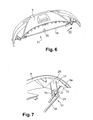
- the bumper skin with butts (the butts being lateral returns of the skin extending substantially perpendicularly to the front face of the skin), the bumper skin is grasped by the butts and " tends the skin like a bow to stabilize it geometrically.
- FIG. 1 there is a painting booth comprising vertical partitions 1, a ceiling (not shown) and a floor 3, a mesh portion 3a corresponds to an air intake.
- the cabin comprises an enclosure comprising a paint installation 10.
- Soil 3 supports a manipulator robot 5 having a movable arm 7 with six degrees of freedom.
- a robot is widespread in the automotive industry and will not be described here.
- the P250 model from FANUK is suitable for implementing the invention.
- the robot carries a large piece which is here a bumper skin 9.
- the end of the arm 7 carries a "universal" gripper, which is composed of a structure 11, two pneumatic cylinders 13, two suckers 15 constituting outlets and four supports 17.
- This gripper is called universal because it is usable, without specific adjustment, with several different parts of the same production campaign. Thus, bumper skins of two or three different models, produced at the same time, can all be handled by the robot without it being necessary to adjust the gripper between two parts.
- the gripper adjustment is only required to prepare it for handling other parts of another production campaign.
- the angular aperture of the structure 11, the stroke of the cylinders 13 or the length of the supports 17 are then adjusted.
- the structure 11 is made of steel (it could also, for example, be aluminum or carbon) and comprises a bar 19 whose two bent ends 21 carry the pneumatic cylinders 13, pivotally articulated around the branches 23 at right angles to the bar 19. In the middle of the bar 19, a handle 20 allows the attachment of the gripper at the end of the arm 7 of the robot.
- the two fixed supports 17 are formed by rods welded to the branch 23 being oriented so that their free ends come into contact with the inner face 25 of the bumper skin 9, as this will be better described with reference to Figures 2 to 5 .
- the movable arm 7 is able, thanks to the universal gripper, to present the bumper skin 9 in front of a projection device 27 located remote from the ceiling of the cabin and supplied with paint by a rigid pipe 29.
- This projection device 27 is fixed and positioned so that a part can be oriented and placed with its part to be treated in front of the projection device.
- the flow of paint droplets projected by the device 27 is sent by the device 27 in the vertical direction, from top to bottom, on the bumper skin.
- the flow is thus oriented as the flow of air entering the grid 3a and as the gravity (gravity). It therefore benefits from optimal conditions to apply evenly over the entire surface to paint bumper skin.
- the surface to be painted is the outer face of the bumper skin. It is covered with a homogeneous layer of paint thanks to the fact that the arm 7 moves the bumper skin 9 so as to present each portion to be painted from this surface at a good distance and for a suitable exposure time.
- the bumper skin 9 is at rest. His butts 9a constitute its most deformable parts.
- the pneumatic cylinders 11 are actuated so as to apply the suction cups 15 against the inner faces of the butts, then air is sucked into each suction cup (as is well known), in order to take hold of the piece by its butts.
- the pneumatic cylinders 11 are actuated in the opposite direction, to "tighten” the bumper skin by imposing a deformed configuration whereby the bumper skin reaches a certain rigidity in its entirety.
- the bumper skin reached the position of the figure 5 and a level of rigidity sufficient to withstand jerks without deforming.
- the skin can withstand rapid movements imposed by the manipulator arm during paint projection operations.
- the bumper skin can thus be presented by the manipulator arm in front of the projection device so that its outer face receives a homogeneous layer of paint (except in places not intended to be painted).
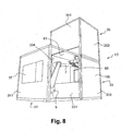
- a paint booth according to another embodiment of the invention is shown for the treatment of painting a workpiece 100.
- This booth is constituted by three enclosures 31, 33, 35 whose dimensions are identical to those of transport containers.
- the cabin also includes a paint installation 10.
- Standard container sizes are 2.44 m wide and 2.59 m high, for containers of 3 m, 6 m and 12 m long.
- the three speakers of figures 8 and 9 have lengths of 3 m, but all known types are usable, possibly with a new distribution of the elements in the different containers.
- the cabins can be assembled together by screwing and grouting.
- the first chamber 31 contains the robot 5. It is provided for this purpose with electrical connections (not shown) for the power of the robot and the lighting of the cabin.
- a window 37 is formed in the closed wall of one of the large side faces 311, which makes it possible to check the proper functioning of the cabin, while the large opposite side face is completely hollowed out.
- the small side faces are, for one, half-closed by a partition 39 extending from the large recessed face halfway to the large window face 311, and the other completely recessed.
- the enclosure 31 has a floor 41 on its underside but no ceiling on its upper face.
- the second chamber 33 is juxtaposed to the first, with one of its large lateral faces 331, which is recessed at the upper three quarters, contiguous to the large recessed face of the first chamber 31. As can be seen in the drawing, this opening allows the manipulator arm 7 of the robot 5 to enter the second chamber 33 to move the piece to be painted 100.
- the other large lateral face 332 of the second enclosure 33 is closed by a wall provided with a window 43 identical to the window 37 of the first chamber 31.
- the two small side faces 333 and 334 of the enclosure are closed by solid walls.
- a retention tank 47 surmounted by two inclined planes 49 with water flow whose function, well known, is to recover the droplets or solid particles of paint which have not reached the surface to be painted in one piece.
- a suction mouth 51 is located at the height of the floor 45 and communicates with a chimney 53 rising, along the small face 334 of the enclosure, to the open upper face of the enclosure 33.
- This chamber 33 is also equipped with connectors (not shown) for its connection to the water network (supply and filtration) and the electrical network for lighting.
- the third enclosure 35 is placed on the second. It has two large lateral faces 351 and 352, one closed to the upper four fifths, the other fully closed, and two small side faces 353 and 354 fully closed.
- the lower face of the enclosure is open, while its upper face has a ceiling 356.
- the air grating 61 located above the second chamber 33, constitutes the ceiling of the paint projection zone.
- the third chamber 35 contains the paint projection device, here constituted by a pipe 63 and an applicator 65. Hoses (not shown) allow the painting of the projection device.
- the third enclosure also contains a chimney 67 which extends, to its ceiling 356, the chimney 53 of the second enclosure 33.
- the three enclosures 31, 33 and 35 constitute a complete painting booth, able to treat efficiently and with a good level of quality pieces to paint of different shapes.
- a fourth enclosure may complete the assembly to delimit a drop zone (drying, flash-off or other) or a fifth enclosure (not shown) may delimit a steaming zone.
- the cabin thus formed is easily removable and transportable, to be reused different factories, and / or re-configurable by "modular" reorganizations to adapt to new products to be treated.
Landscapes
- Spray Control Apparatus (AREA)
- Details Or Accessories Of Spraying Plant Or Apparatus (AREA)
- Application Of Or Painting With Fluid Materials (AREA)
Priority Applications (1)
| Application Number | Priority Date | Filing Date | Title |
|---|---|---|---|
| PL10807713T PL2519360T3 (pl) | 2009-12-29 | 2010-12-28 | Sposób obróbki powierzchniowej części o dużych wymiarach, uchwyt części dostosowany do stosowania takiego sposobu, zastosowanie uchwytu i kabina obróbcza |
Applications Claiming Priority (2)
| Application Number | Priority Date | Filing Date | Title |
|---|---|---|---|
| FR0959647A FR2954716B1 (fr) | 2009-12-29 | 2009-12-29 | Procede de traitement surfacique de pieces de grandes dimensions, prehenseur de pieces adapte pour la mise en oeuvre d'un tel procede, utilisation de ce prehenseur et cabine de traitement |
| PCT/FR2010/052927 WO2011080484A1 (fr) | 2009-12-29 | 2010-12-28 | Procédé de traitement surfacique de pièces de grandes dimensions, préhenseur de pièces adapté pour la mise en oeuvre d'un tel procédé, utilisation de ce préhenseur et cabine de traitement |
Publications (2)
| Publication Number | Publication Date |
|---|---|
| EP2519360A1 EP2519360A1 (fr) | 2012-11-07 |
| EP2519360B1 true EP2519360B1 (fr) | 2016-11-30 |
Family
ID=42320852
Family Applications (1)
| Application Number | Title | Priority Date | Filing Date |
|---|---|---|---|
| EP10807713.2A Not-in-force EP2519360B1 (fr) | 2009-12-29 | 2010-12-28 | Procédé de traitement surfacique de pièces de grandes dimensions, préhenseur de pièces adapté pour la mise en oeuvre d'un tel procédé, utilisation de ce préhenseur et cabine de traitement |
Country Status (10)
| Country | Link |
|---|---|
| US (1) | US9005715B2 (pl) |
| EP (1) | EP2519360B1 (pl) |
| CN (1) | CN102883820B (pl) |
| AR (1) | AR081798A1 (pl) |
| BR (1) | BR112012016081A2 (pl) |
| FR (1) | FR2954716B1 (pl) |
| MX (1) | MX337103B (pl) |
| PL (1) | PL2519360T3 (pl) |
| RU (1) | RU2558583C2 (pl) |
| WO (1) | WO2011080484A1 (pl) |
Families Citing this family (19)
| Publication number | Priority date | Publication date | Assignee | Title |
|---|---|---|---|---|
| DE102009060649A1 (de) * | 2009-12-22 | 2011-06-30 | EISENMANN Anlagenbau GmbH & Co. KG, 71032 | Anlage zur Oberflächenbehandlung von Gegenständen |
| FR2981598B1 (fr) | 2011-10-25 | 2017-03-10 | Plastic Omnium Cie | Prehenseur de piece a peindre pour robot manipulateur |
| FR2994197B1 (fr) * | 2012-08-06 | 2014-08-22 | Plastic Omnium Cie | Procede de metallisation d'une surface d'une piece pour vehicule automobile |
| FR2994196B1 (fr) * | 2012-08-06 | 2014-08-22 | Plastic Omnium Cie | Procede de metallisation d'une piece pour vehicule automobile |
| JP2015100761A (ja) * | 2013-11-26 | 2015-06-04 | 曙ブレーキ工業株式会社 | 支持具、粉体塗布システム、粉体塗布方法、及びキャリパ |
| JP6263442B2 (ja) * | 2014-05-26 | 2018-01-17 | 株式会社大気社 | 塗装設備 |
| DE102015110264A1 (de) * | 2015-06-25 | 2016-12-29 | Cl Schutzrechtsverwaltungs Gmbh | Vorrichtung zur generativen Herstellung wenigstens eines dreidimensionalen Objekts |
| EP3117965B1 (fr) * | 2015-07-16 | 2018-02-28 | ETA SA Manufacture Horlogère Suisse | Poste de travail ergonomique pour horloger |
| ITUB20160922A1 (it) | 2016-02-22 | 2017-08-22 | Varnish Tech S R L | Impianto e metodo di verniciatura. |
| CN107081239B (zh) * | 2017-06-09 | 2022-08-16 | 东莞市新力光表面处理科技有限公司 | 一种汽车后视镜自动喷涂系统 |
| CN107930938A (zh) * | 2017-12-18 | 2018-04-20 | 宁波斯凯勒智能科技有限公司 | 一种机械生产用均匀喷漆装置 |
| CN111923026A (zh) * | 2020-08-10 | 2020-11-13 | 中国人民解放军第五七一九工厂 | 航空发动机压气机叶片榫头智能自动硅胶涂覆系统及方法 |
| CN112474144B (zh) * | 2020-11-26 | 2021-10-29 | 安徽橡树工业设计有限公司 | 一种用于车间设备保护的自动喷涂设备及其使用方法 |
| CN113145429A (zh) * | 2021-03-16 | 2021-07-23 | 安徽工程大学 | 一种汽车前机盖喷涂方法 |
| CN113457893A (zh) * | 2021-06-30 | 2021-10-01 | 浙江鼎能新材料有限公司 | 静电喷涂室的粉末回收结构 |
| JP2024531126A (ja) * | 2021-08-10 | 2024-08-29 | カティーバ, インコーポレイテッド | 基材位置調整機能を有する基材準備チャンバ |
| CN114453178A (zh) * | 2022-01-14 | 2022-05-10 | 湖北邱氏节能建材高新技术股份有限公司 | 一种建筑用磷石膏轻质材料喷涂装置及其喷涂方法 |
| CN115338063B (zh) * | 2022-08-05 | 2023-11-07 | 安徽九洲华隆实木家俬有限公司 | 一种实木家具喷漆工艺及设备 |
| CN116921114B (zh) * | 2023-09-15 | 2024-01-05 | 靖江市国恒汽配制造有限公司 | 一种汽车保险杠喷涂设备 |
Family Cites Families (11)
| Publication number | Priority date | Publication date | Assignee | Title |
|---|---|---|---|---|
| EP0532774B1 (de) * | 1991-09-16 | 1996-02-28 | SIG - Schweizerische Industrie-Gesellschaft | Greifer für einen Manipulator |
| US5743958A (en) * | 1993-05-25 | 1998-04-28 | Nordson Corporation | Vehicle powder coating system |
| DE69321617T2 (de) * | 1993-07-19 | 1999-04-22 | Abb Trallfa Robot A/S, Bryne | In eine sprühbeschichtungskabine installierte robotereinrichtung |
| WO1997036712A1 (en) * | 1996-04-01 | 1997-10-09 | Johnson Bryan T | Automotive bumper stand |
| RU2163189C1 (ru) * | 1999-12-07 | 2001-02-20 | Акинфиев Теодор Самуилович | Устройство для автоматической технологической обработки деталей |
| RU16834U1 (ru) * | 2000-06-14 | 2001-02-20 | Стерник Юрий Мордко-Львович | Манипулятор |
| US7445184B1 (en) * | 2003-05-05 | 2008-11-04 | Innovative Tools & Technologies, Inc. | Mobile paint rack |
| DE102005033972A1 (de) * | 2005-07-20 | 2007-01-25 | Dürr Systems GmbH | Beschichtungsverfahren und zugehörige Beschichtungseinrichtung |
| JP4249789B2 (ja) * | 2007-07-23 | 2009-04-08 | ファナック株式会社 | 可撓性ワーク組付方法 |
| DE102007063163B4 (de) * | 2007-12-19 | 2009-12-10 | Karl-Heinz Fehr | Beschichtungsanlage |
| DE102007063162B3 (de) * | 2007-12-19 | 2009-03-05 | Karl-Heinz Fehr | Modulartig zusammengesetzte Beschichtungszelle |
-
2009
- 2009-12-29 FR FR0959647A patent/FR2954716B1/fr not_active Expired - Fee Related
-
2010
- 2010-12-28 CN CN201080064386.2A patent/CN102883820B/zh not_active Expired - Fee Related
- 2010-12-28 PL PL10807713T patent/PL2519360T3/pl unknown
- 2010-12-28 EP EP10807713.2A patent/EP2519360B1/fr not_active Not-in-force
- 2010-12-28 MX MX2012007551A patent/MX337103B/es active IP Right Grant
- 2010-12-28 RU RU2012132461/05A patent/RU2558583C2/ru not_active IP Right Cessation
- 2010-12-28 BR BR112012016081A patent/BR112012016081A2/pt not_active IP Right Cessation
- 2010-12-28 WO PCT/FR2010/052927 patent/WO2011080484A1/fr not_active Ceased
- 2010-12-28 US US13/519,164 patent/US9005715B2/en not_active Expired - Fee Related
- 2010-12-29 AR ARP100104987A patent/AR081798A1/es not_active Application Discontinuation
Also Published As
| Publication number | Publication date |
|---|---|
| CN102883820A (zh) | 2013-01-16 |
| WO2011080484A1 (fr) | 2011-07-07 |
| MX337103B (es) | 2016-02-09 |
| US20130026676A1 (en) | 2013-01-31 |
| RU2012132461A (ru) | 2014-02-10 |
| BR112012016081A2 (pt) | 2018-05-29 |
| EP2519360A1 (fr) | 2012-11-07 |
| FR2954716B1 (fr) | 2012-02-10 |
| AR081798A1 (es) | 2012-10-24 |
| MX2012007551A (es) | 2012-11-29 |
| CN102883820B (zh) | 2015-11-25 |
| PL2519360T3 (pl) | 2017-06-30 |
| FR2954716A1 (fr) | 2011-07-01 |
| US9005715B2 (en) | 2015-04-14 |
| RU2558583C2 (ru) | 2015-08-10 |
Similar Documents
| Publication | Publication Date | Title |
|---|---|---|
| EP2519360B1 (fr) | Procédé de traitement surfacique de pièces de grandes dimensions, préhenseur de pièces adapté pour la mise en oeuvre d'un tel procédé, utilisation de ce préhenseur et cabine de traitement | |
| FR2698292A1 (fr) | Installation de peinture à poudre munie d'une cabine à section variable. | |
| EP2500152A1 (fr) | Procédé de préhension d'objets, de mise en place dans une caisse et de préhension de cette caisse | |
| WO2004103574A2 (fr) | Dispositif de retouche automatique pour cabine de poudrage | |
| WO1994022590A1 (fr) | Machine de projection de produit de revetement | |
| EP0720515B1 (fr) | Dispositif de projection de produit de revetement formant machine de toit ou machine laterale | |
| EP4015093B1 (fr) | Robot, système et procédé de poudrage électrostatique | |
| EP0375511B1 (fr) | Procédé et installation d'application d'un produit de revêtement | |
| EP0723817B1 (fr) | Cabine de traitement de pièces par pulvérisation | |
| JP6909579B2 (ja) | 塗装ブース | |
| EP3878563B1 (fr) | Embase pour une cabine de poudrage | |
| FR3065711A1 (fr) | Machine de formage de cartons | |
| US20080223296A1 (en) | Paint Booth For Plants For Painting Products | |
| EP3694319A1 (fr) | Panneau de récupération | |
| EP0320378A1 (fr) | Procédé et dispositif de projection d'un produit sur les faces opposées d'un panneau | |
| CH635524A5 (fr) | Installation de poudrage electrostatique. | |
| EP1357000B1 (fr) | Dispositif et procédé de pliage de sac gonflable pour dispositif de sécurité de véhicule automobile | |
| EP3307506B1 (fr) | Installation de réalisation de préformes composites thermoplastiques | |
| EP1297945A1 (fr) | Machine d'assemblage de feuilles de matières plastiques de grandes dimensions | |
| FR2666522A1 (fr) | Procede et machine de pulverisation de liquide, notamment pour l'encollage ou la teinture de pieces en cuir. | |
| FR2922789A1 (fr) | Installation industrielle de peinture. | |
| EP2586955B1 (fr) | Installation pour la pose d'une pareclose sur la feuillure d'un longeron constitutif d'un cadre d'une menuiserie recevant un vitrage | |
| FR3057797A1 (fr) | Robot industriel de manipulation de chassis de moulage et installation de moulage comprenant au moins un tel robot | |
| WO2007028873A1 (fr) | Installation de peinture | |
| FR2777825A1 (fr) | Agencement perfectionne, applicable a la finition des elements de cuisine, salle de bains et analogues |
Legal Events
| Date | Code | Title | Description |
|---|---|---|---|
| PUAI | Public reference made under article 153(3) epc to a published international application that has entered the european phase |
Free format text: ORIGINAL CODE: 0009012 |
|
| 17P | Request for examination filed |
Effective date: 20120724 |
|
| AK | Designated contracting states |
Kind code of ref document: A1 Designated state(s): AL AT BE BG CH CY CZ DE DK EE ES FI FR GB GR HR HU IE IS IT LI LT LU LV MC MK MT NL NO PL PT RO RS SE SI SK SM TR |
|
| DAX | Request for extension of the european patent (deleted) | ||
| GRAP | Despatch of communication of intention to grant a patent |
Free format text: ORIGINAL CODE: EPIDOSNIGR1 |
|
| INTG | Intention to grant announced |
Effective date: 20160614 |
|
| GRAS | Grant fee paid |
Free format text: ORIGINAL CODE: EPIDOSNIGR3 |
|
| GRAA | (expected) grant |
Free format text: ORIGINAL CODE: 0009210 |
|
| AK | Designated contracting states |
Kind code of ref document: B1 Designated state(s): AL AT BE BG CH CY CZ DE DK EE ES FI FR GB GR HR HU IE IS IT LI LT LU LV MC MK MT NL NO PL PT RO RS SE SI SK SM TR |
|
| REG | Reference to a national code |
Ref country code: CH Ref legal event code: EP Ref country code: GB Ref legal event code: FG4D Free format text: NOT ENGLISH |
|
| REG | Reference to a national code |
Ref country code: AT Ref legal event code: REF Ref document number: 849299 Country of ref document: AT Kind code of ref document: T Effective date: 20161215 |
|
| REG | Reference to a national code |
Ref country code: FR Ref legal event code: PLFP Year of fee payment: 7 |
|
| REG | Reference to a national code |
Ref country code: IE Ref legal event code: FG4D Free format text: LANGUAGE OF EP DOCUMENT: FRENCH |
|
| REG | Reference to a national code |
Ref country code: DE Ref legal event code: R096 Ref document number: 602010038500 Country of ref document: DE |
|
| PG25 | Lapsed in a contracting state [announced via postgrant information from national office to epo] |
Ref country code: LV Free format text: LAPSE BECAUSE OF FAILURE TO SUBMIT A TRANSLATION OF THE DESCRIPTION OR TO PAY THE FEE WITHIN THE PRESCRIBED TIME-LIMIT Effective date: 20161130 |
|
| REG | Reference to a national code |
Ref country code: LT Ref legal event code: MG4D |
|
| REG | Reference to a national code |
Ref country code: NL Ref legal event code: MP Effective date: 20161130 |
|
| REG | Reference to a national code |
Ref country code: AT Ref legal event code: MK05 Ref document number: 849299 Country of ref document: AT Kind code of ref document: T Effective date: 20161130 |
|
| PG25 | Lapsed in a contracting state [announced via postgrant information from national office to epo] |
Ref country code: LT Free format text: LAPSE BECAUSE OF FAILURE TO SUBMIT A TRANSLATION OF THE DESCRIPTION OR TO PAY THE FEE WITHIN THE PRESCRIBED TIME-LIMIT Effective date: 20161130 Ref country code: NO Free format text: LAPSE BECAUSE OF FAILURE TO SUBMIT A TRANSLATION OF THE DESCRIPTION OR TO PAY THE FEE WITHIN THE PRESCRIBED TIME-LIMIT Effective date: 20170228 Ref country code: SE Free format text: LAPSE BECAUSE OF FAILURE TO SUBMIT A TRANSLATION OF THE DESCRIPTION OR TO PAY THE FEE WITHIN THE PRESCRIBED TIME-LIMIT Effective date: 20161130 Ref country code: GR Free format text: LAPSE BECAUSE OF FAILURE TO SUBMIT A TRANSLATION OF THE DESCRIPTION OR TO PAY THE FEE WITHIN THE PRESCRIBED TIME-LIMIT Effective date: 20170301 |
|
| PG25 | Lapsed in a contracting state [announced via postgrant information from national office to epo] |
Ref country code: FI Free format text: LAPSE BECAUSE OF FAILURE TO SUBMIT A TRANSLATION OF THE DESCRIPTION OR TO PAY THE FEE WITHIN THE PRESCRIBED TIME-LIMIT Effective date: 20161130 Ref country code: PT Free format text: LAPSE BECAUSE OF FAILURE TO SUBMIT A TRANSLATION OF THE DESCRIPTION OR TO PAY THE FEE WITHIN THE PRESCRIBED TIME-LIMIT Effective date: 20170330 Ref country code: BE Free format text: LAPSE BECAUSE OF NON-PAYMENT OF DUE FEES Effective date: 20161231 Ref country code: HR Free format text: LAPSE BECAUSE OF FAILURE TO SUBMIT A TRANSLATION OF THE DESCRIPTION OR TO PAY THE FEE WITHIN THE PRESCRIBED TIME-LIMIT Effective date: 20161130 Ref country code: AT Free format text: LAPSE BECAUSE OF FAILURE TO SUBMIT A TRANSLATION OF THE DESCRIPTION OR TO PAY THE FEE WITHIN THE PRESCRIBED TIME-LIMIT Effective date: 20161130 Ref country code: ES Free format text: LAPSE BECAUSE OF FAILURE TO SUBMIT A TRANSLATION OF THE DESCRIPTION OR TO PAY THE FEE WITHIN THE PRESCRIBED TIME-LIMIT Effective date: 20161130 Ref country code: RS Free format text: LAPSE BECAUSE OF FAILURE TO SUBMIT A TRANSLATION OF THE DESCRIPTION OR TO PAY THE FEE WITHIN THE PRESCRIBED TIME-LIMIT Effective date: 20161130 |
|
| PG25 | Lapsed in a contracting state [announced via postgrant information from national office to epo] |
Ref country code: NL Free format text: LAPSE BECAUSE OF FAILURE TO SUBMIT A TRANSLATION OF THE DESCRIPTION OR TO PAY THE FEE WITHIN THE PRESCRIBED TIME-LIMIT Effective date: 20161130 |
|
| PG25 | Lapsed in a contracting state [announced via postgrant information from national office to epo] |
Ref country code: DK Free format text: LAPSE BECAUSE OF FAILURE TO SUBMIT A TRANSLATION OF THE DESCRIPTION OR TO PAY THE FEE WITHIN THE PRESCRIBED TIME-LIMIT Effective date: 20161130 Ref country code: EE Free format text: LAPSE BECAUSE OF FAILURE TO SUBMIT A TRANSLATION OF THE DESCRIPTION OR TO PAY THE FEE WITHIN THE PRESCRIBED TIME-LIMIT Effective date: 20161130 Ref country code: RO Free format text: LAPSE BECAUSE OF FAILURE TO SUBMIT A TRANSLATION OF THE DESCRIPTION OR TO PAY THE FEE WITHIN THE PRESCRIBED TIME-LIMIT Effective date: 20161130 |
|
| REG | Reference to a national code |
Ref country code: CH Ref legal event code: PL |
|
| PG25 | Lapsed in a contracting state [announced via postgrant information from national office to epo] |
Ref country code: SM Free format text: LAPSE BECAUSE OF FAILURE TO SUBMIT A TRANSLATION OF THE DESCRIPTION OR TO PAY THE FEE WITHIN THE PRESCRIBED TIME-LIMIT Effective date: 20161130 Ref country code: BG Free format text: LAPSE BECAUSE OF FAILURE TO SUBMIT A TRANSLATION OF THE DESCRIPTION OR TO PAY THE FEE WITHIN THE PRESCRIBED TIME-LIMIT Effective date: 20170228 Ref country code: IT Free format text: LAPSE BECAUSE OF FAILURE TO SUBMIT A TRANSLATION OF THE DESCRIPTION OR TO PAY THE FEE WITHIN THE PRESCRIBED TIME-LIMIT Effective date: 20161130 |
|
| REG | Reference to a national code |
Ref country code: DE Ref legal event code: R097 Ref document number: 602010038500 Country of ref document: DE |
|
| PG25 | Lapsed in a contracting state [announced via postgrant information from national office to epo] |
Ref country code: MC Free format text: LAPSE BECAUSE OF FAILURE TO SUBMIT A TRANSLATION OF THE DESCRIPTION OR TO PAY THE FEE WITHIN THE PRESCRIBED TIME-LIMIT Effective date: 20161130 |
|
| REG | Reference to a national code |
Ref country code: SK Ref legal event code: T3 Ref document number: E 24215 Country of ref document: SK |
|
| REG | Reference to a national code |
Ref country code: IE Ref legal event code: MM4A |
|
| PLBE | No opposition filed within time limit |
Free format text: ORIGINAL CODE: 0009261 |
|
| STAA | Information on the status of an ep patent application or granted ep patent |
Free format text: STATUS: NO OPPOSITION FILED WITHIN TIME LIMIT |
|
| PG25 | Lapsed in a contracting state [announced via postgrant information from national office to epo] |
Ref country code: LU Free format text: LAPSE BECAUSE OF NON-PAYMENT OF DUE FEES Effective date: 20161228 Ref country code: CH Free format text: LAPSE BECAUSE OF NON-PAYMENT OF DUE FEES Effective date: 20161231 Ref country code: LI Free format text: LAPSE BECAUSE OF NON-PAYMENT OF DUE FEES Effective date: 20161231 |
|
| 26N | No opposition filed |
Effective date: 20170831 |
|
| PG25 | Lapsed in a contracting state [announced via postgrant information from national office to epo] |
Ref country code: IE Free format text: LAPSE BECAUSE OF NON-PAYMENT OF DUE FEES Effective date: 20161228 Ref country code: SI Free format text: LAPSE BECAUSE OF FAILURE TO SUBMIT A TRANSLATION OF THE DESCRIPTION OR TO PAY THE FEE WITHIN THE PRESCRIBED TIME-LIMIT Effective date: 20161130 |
|
| REG | Reference to a national code |
Ref country code: FR Ref legal event code: PLFP Year of fee payment: 8 |
|
| REG | Reference to a national code |
Ref country code: BE Ref legal event code: MM Effective date: 20161231 |
|
| PG25 | Lapsed in a contracting state [announced via postgrant information from national office to epo] |
Ref country code: CY Free format text: LAPSE BECAUSE OF FAILURE TO SUBMIT A TRANSLATION OF THE DESCRIPTION OR TO PAY THE FEE WITHIN THE PRESCRIBED TIME-LIMIT Effective date: 20161130 Ref country code: HU Free format text: LAPSE BECAUSE OF FAILURE TO SUBMIT A TRANSLATION OF THE DESCRIPTION OR TO PAY THE FEE WITHIN THE PRESCRIBED TIME-LIMIT; INVALID AB INITIO Effective date: 20101228 |
|
| PG25 | Lapsed in a contracting state [announced via postgrant information from national office to epo] |
Ref country code: MK Free format text: LAPSE BECAUSE OF FAILURE TO SUBMIT A TRANSLATION OF THE DESCRIPTION OR TO PAY THE FEE WITHIN THE PRESCRIBED TIME-LIMIT Effective date: 20161130 Ref country code: TR Free format text: LAPSE BECAUSE OF FAILURE TO SUBMIT A TRANSLATION OF THE DESCRIPTION OR TO PAY THE FEE WITHIN THE PRESCRIBED TIME-LIMIT Effective date: 20161130 Ref country code: IS Free format text: LAPSE BECAUSE OF FAILURE TO SUBMIT A TRANSLATION OF THE DESCRIPTION OR TO PAY THE FEE WITHIN THE PRESCRIBED TIME-LIMIT Effective date: 20161130 |
|
| PG25 | Lapsed in a contracting state [announced via postgrant information from national office to epo] |
Ref country code: MT Free format text: LAPSE BECAUSE OF FAILURE TO SUBMIT A TRANSLATION OF THE DESCRIPTION OR TO PAY THE FEE WITHIN THE PRESCRIBED TIME-LIMIT Effective date: 20161130 |
|
| PGFP | Annual fee paid to national office [announced via postgrant information from national office to epo] |
Ref country code: CZ Payment date: 20181227 Year of fee payment: 9 Ref country code: DE Payment date: 20181210 Year of fee payment: 9 Ref country code: PL Payment date: 20181211 Year of fee payment: 9 Ref country code: SK Payment date: 20181213 Year of fee payment: 9 |
|
| PGFP | Annual fee paid to national office [announced via postgrant information from national office to epo] |
Ref country code: GB Payment date: 20181218 Year of fee payment: 9 Ref country code: FR Payment date: 20181220 Year of fee payment: 9 |
|
| REG | Reference to a national code |
Ref country code: DE Ref legal event code: R119 Ref document number: 602010038500 Country of ref document: DE |
|
| PG25 | Lapsed in a contracting state [announced via postgrant information from national office to epo] |
Ref country code: AL Free format text: LAPSE BECAUSE OF FAILURE TO SUBMIT A TRANSLATION OF THE DESCRIPTION OR TO PAY THE FEE WITHIN THE PRESCRIBED TIME-LIMIT Effective date: 20161130 Ref country code: CZ Free format text: LAPSE BECAUSE OF NON-PAYMENT OF DUE FEES Effective date: 20191228 |
|
| GBPC | Gb: european patent ceased through non-payment of renewal fee |
Effective date: 20191228 |
|
| REG | Reference to a national code |
Ref country code: SK Ref legal event code: MM4A Ref document number: E 24215 Country of ref document: SK Effective date: 20191228 |
|
| PG25 | Lapsed in a contracting state [announced via postgrant information from national office to epo] |
Ref country code: SK Free format text: LAPSE BECAUSE OF NON-PAYMENT OF DUE FEES Effective date: 20191228 Ref country code: DE Free format text: LAPSE BECAUSE OF NON-PAYMENT OF DUE FEES Effective date: 20200701 Ref country code: GB Free format text: LAPSE BECAUSE OF NON-PAYMENT OF DUE FEES Effective date: 20191228 Ref country code: FR Free format text: LAPSE BECAUSE OF NON-PAYMENT OF DUE FEES Effective date: 20191231 |
|
| PG25 | Lapsed in a contracting state [announced via postgrant information from national office to epo] |
Ref country code: PL Free format text: LAPSE BECAUSE OF NON-PAYMENT OF DUE FEES Effective date: 20191228 |