EP2516020B1 - Fall protection safety device with a braking mechanism - Google Patents
Fall protection safety device with a braking mechanism Download PDFInfo
- Publication number
- EP2516020B1 EP2516020B1 EP10801071.1A EP10801071A EP2516020B1 EP 2516020 B1 EP2516020 B1 EP 2516020B1 EP 10801071 A EP10801071 A EP 10801071A EP 2516020 B1 EP2516020 B1 EP 2516020B1
- Authority
- EP
- European Patent Office
- Prior art keywords
- component
- housing
- drum
- magnet
- self
- Prior art date
- Legal status (The legal status is an assumption and is not a legal conclusion. Google has not performed a legal analysis and makes no representation as to the accuracy of the status listed.)
- Active
Links
- 230000007246 mechanism Effects 0.000 title claims description 26
- 239000004020 conductor Substances 0.000 claims description 15
- 230000005294 ferromagnetic effect Effects 0.000 claims description 15
- 229910052782 aluminium Inorganic materials 0.000 claims description 8
- XAGFODPZIPBFFR-UHFFFAOYSA-N aluminium Chemical compound [Al] XAGFODPZIPBFFR-UHFFFAOYSA-N 0.000 claims description 8
- 230000005672 electromagnetic field Effects 0.000 claims description 3
- 239000000356 contaminant Substances 0.000 description 6
- 230000005291 magnetic effect Effects 0.000 description 3
- 230000002452 interceptive effect Effects 0.000 description 2
- 238000009987 spinning Methods 0.000 description 2
- 229910001369 Brass Inorganic materials 0.000 description 1
- RYGMFSIKBFXOCR-UHFFFAOYSA-N Copper Chemical compound [Cu] RYGMFSIKBFXOCR-UHFFFAOYSA-N 0.000 description 1
- 239000004593 Epoxy Substances 0.000 description 1
- CBENFWSGALASAD-UHFFFAOYSA-N Ozone Chemical compound [O-][O+]=O CBENFWSGALASAD-UHFFFAOYSA-N 0.000 description 1
- 239000006096 absorbing agent Substances 0.000 description 1
- 239000000853 adhesive Substances 0.000 description 1
- 230000001070 adhesive effect Effects 0.000 description 1
- 239000010951 brass Substances 0.000 description 1
- 229910052802 copper Inorganic materials 0.000 description 1
- 239000010949 copper Substances 0.000 description 1
- 230000000694 effects Effects 0.000 description 1
- 230000005484 gravity Effects 0.000 description 1
- 239000004519 grease Substances 0.000 description 1
- 238000002955 isolation Methods 0.000 description 1
- 238000004519 manufacturing process Methods 0.000 description 1
- 229910052751 metal Inorganic materials 0.000 description 1
- 239000002184 metal Substances 0.000 description 1
- 239000000203 mixture Substances 0.000 description 1
- 239000003921 oil Substances 0.000 description 1
- 125000006850 spacer group Chemical group 0.000 description 1
- 229910001220 stainless steel Inorganic materials 0.000 description 1
- 239000010935 stainless steel Substances 0.000 description 1
- 230000003068 static effect Effects 0.000 description 1
- XLYOFNOQVPJJNP-UHFFFAOYSA-N water Substances O XLYOFNOQVPJJNP-UHFFFAOYSA-N 0.000 description 1
Images


Classifications
-
- A—HUMAN NECESSITIES
- A62—LIFE-SAVING; FIRE-FIGHTING
- A62B—DEVICES, APPARATUS OR METHODS FOR LIFE-SAVING
- A62B1/00—Devices for lowering persons from buildings or the like
- A62B1/06—Devices for lowering persons from buildings or the like by making use of rope-lowering devices
- A62B1/14—Devices for lowering persons from buildings or the like by making use of rope-lowering devices with brakes sliding on the rope
-
- H—ELECTRICITY
- H02—GENERATION; CONVERSION OR DISTRIBUTION OF ELECTRIC POWER
- H02K—DYNAMO-ELECTRIC MACHINES
- H02K49/00—Dynamo-electric clutches; Dynamo-electric brakes
- H02K49/02—Dynamo-electric clutches; Dynamo-electric brakes of the asynchronous induction type
- H02K49/04—Dynamo-electric clutches; Dynamo-electric brakes of the asynchronous induction type of the eddy-current hysteresis type
- H02K49/043—Dynamo-electric clutches; Dynamo-electric brakes of the asynchronous induction type of the eddy-current hysteresis type with a radial airgap
-
- A—HUMAN NECESSITIES
- A62—LIFE-SAVING; FIRE-FIGHTING
- A62B—DEVICES, APPARATUS OR METHODS FOR LIFE-SAVING
- A62B35/00—Safety belts or body harnesses; Similar equipment for limiting displacement of the human body, especially in case of sudden changes of motion
- A62B35/0081—Equipment which can travel along the length of a lifeline, e.g. travelers
-
- A—HUMAN NECESSITIES
- A62—LIFE-SAVING; FIRE-FIGHTING
- A62B—DEVICES, APPARATUS OR METHODS FOR LIFE-SAVING
- A62B35/00—Safety belts or body harnesses; Similar equipment for limiting displacement of the human body, especially in case of sudden changes of motion
- A62B35/0043—Lifelines, lanyards, and anchors therefore
- A62B35/0062—Rail-form lifelines for permanent installation
Definitions
- the present invention relates to a fall protection safety device including a braking mechanism.
- Fall protection safety devices are well known in the art of fall protection safety equipment for use by workers performing tasks during which there is a risk a fall may occur.
- One type of safety device commonly used is a rail along the length of which a shuttle moves.
- the rail is typically connected to a support structure within the vicinity the worker is performing the task, and the shuttle is typically connected to a safety harness worn by the worker.
- An energy absorber may also be used with this type of safety device to reduce the amount of force transferred to the worker. Should a fall occur, the shuttle locks onto the rail thereby preventing the worker from falling any further. If the shuttle becomes contaminated with dirt, oil, grease, water, ice, or other types of debris or contaminants, the shuttle may not operate properly.
- One type of commonly used shuttle utilizes a wheel that rides on a rail or track to sense speed, and the wheel could be affected by contaminants. If the wheel has a rubber grip, the rubber grip could be degraded by ultraviolet light or ozone exposure.
- a known safety device is disclosed in document WO 2009/108040 A1 .
- the two-part form of claim 1 is based on this document.
- a self-retracting lifeline generally includes a housing containing a drum around which a cable, rope, webbing, or other suitable lifeline is wound.
- the drum is spring biased to pay out cable as tension pulling the cable is applied and to retract any of the cable that has been unwound from the drum as the tension on the cable is reduced or released.
- the housing also includes a brake assembly for stopping rotation of the drum when the cable suddenly unwinds from the drum at a rate greater than a predetermined maximum angular velocity.
- a self-retracting lifeline is typically connected to a support structure within the vicinity the worker is performing the task, and the end of the cable is typically connected to a safety harness worn by the worker.
- the support structure may include one or more structures.
- the cable is easily drawn out of the self-retracting lifeline housing as the worker moves away from the device, and the cable is automatically drawn back into the housing as the worker moves toward the device. Should a fall occur, the brake assembly within the device is automatically engaged by a centrifugal clutch assembly, which gradually and quickly stops the worker's fall by gradually and quickly stopping the rotation of the drum. As the rotation of the drum is stopped, additional cable is prevented from being paid out of the housing to stop the fall of the worker.
- Some self-retracting lifelines are sealed to prevent contaminants from interfering with the braking or locking mechanism.
- Another type of safety device commonly used is a descender or a controlled descent device, which generally include a braking mechanism to allow the worker to slowly descend to a safe location.
- the at least one magnet and the non-ferromagnetic and electrically conductive material creating an electromagnetic field force when the second component moves at a rate greater than a predetermined rate relative to the first component.
- the housing is configured and arranged to move along a support structure being from the group consisting of a rail, a track, and a cable and being made of a non-ferromagnetic and electrically conductive material.
- the pawl is pivotally connected to the housing and is configured and arranged to move from a disengaged position into an engaged position when the housing moves along the support structure at a rate greater than a predetermined rate to lock the housing onto the support structure.
- the magnet is operatively connected to the pawl such that when the housing moves at an increased rate repulsive forces between the magnet and the support structure assist in moving the pawl from the disengaged position into the engaged position.
- a fall protection safety device comprises a housing, a drum, at least one magnet, and a lifeline.
- the drum is rotatably operatively connected to the housing and rotates in a first direction and a second direction.
- the at least one magnet is operatively connected to one of the housing and the drum, and another of the housing and the drum is at least partially made of a non-ferromagnetic and electrically conductive material.
- the lifeline is operatively connected to the drum.
- the intermediate portion of the lifeline is at least partially wound about the drum and the second end extends outward from the housing.
- the lifeline is paid out from the housing when sufficient tension is placed on the lifeline thereby rotating the drum.
- a repulsion force between the at least one magnet and the non-ferromagnetic and electrically conductive material reduces a rate at which the drum rotates in at least one of the first direction and the second direction.
- the present invention generally relates to a braking mechanism for use with a fall protection safety device.
- the braking mechanism could act as a brake, a lock, and/or a trigger mechanism suitable for the type of fall protection safety device.
- One type of fall protection safety device with which the present invention could be used is a shuttle.
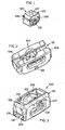
- An embodiment shuttle constructed according to the principles of the present invention is designated by the numeral 100 in the drawings.
- the shuttle 100 includes a housing 101 and a pawl 120.
- the housing 101 includes a front 102 from which a first side 104 and a second side 107 extend downward.
- the front 102 has an opening 103 proximate the center of the front 102
- the first side 104 has an opening 105 proximate the center of the first side 104
- the second side 107 has an opening 108 proximate the center of the second side 107.
- the first side 104 also includes an aperture (not shown) between the opening 105 and the front 102
- the second side 107 also includes an aperture (not shown) between the opening 108 and the front 102.
- a flange 106 extends inward from the bottom of the first side 104, and a flange 109 extends inward from the bottom of the second side 107.
- the housing 101 also includes a top 110 and a bottom 112. The area between the front 102 and the flanges 106 and 109 form a channel 112 extending from the top 110 to the bottom 111.
- the pawl 120 includes sides 128 interconnecting a front 121 and a rear 124.
- the rear 124 includes a first surface 125 proximate the top and a second surface 126 proximate the bottom.
- the surfaces 125 and 126 are approximately spiral-shaped, preferably a logarithmic spiral, and are symmetric about a plane passing through the theoretical axis of bore 122 and perpendicular to the face of the magnet 127.
- the rear 124 includes a magnet 127, which is preferably embedded into the pawl 120.
- a bore 122 extends laterally through the sides 128, and a fastener 123 extends through the apertures in the sides 104 and 107 of the housing 101 and the bore 122 of the pawl 120 to interconnect the housing 101 and the pawl 120.
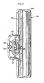
- the shuttle 100 is configured and arranged to slide along the length of a rail 130, which is preferably made of aluminum, copper, brass, stainless steel, or any other suitable electrically conductive metal with insignificant static magnetic field attraction force.
- the rail 130 includes a flange 131 extending outward from a base 134.
- the flange 131 has a first side 132 and a second side 133.
- the base 134 includes apertures for attaching the base 134 to a support structure.
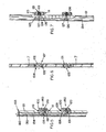
- the pawl 120 will pivot from a disengaged or unlocked position 140 to an engaged or locked position 150 and prevent further movement of the shuttle 100 along the rail 130.
- the magnet 127 in the pawl 120 generates a force, a changing magnetic field that pushes electrons around in a circular, eddy current, and in the orientation shown in Figure 7 , downward movement along the rail 130 at a speed greater than a predetermined speed makes the magnet 127 want to move upward. This is in accordance with Lenz's Law.
- the magnet 127 is positioned in an orientation such that the magnetic field is concentrated proximate the rail, and north or south polarity of the magnet 127 does not matter.
- the surfaces 125 and 126 of the pawl 120 are angled so that when the pawl 120 pivots in a first or second direction, the corresponding surface is configured and arranged to engage the rail 130 to which the shuttle 100 is connected.
- the second surface 126 is an engaging surface when the shuttle is moved in a downward direction to engage the rail 130 and prevent a worker from falling.
- the braking mechanism acts as a lock because the pawl pivots to engage the rail and prevent the shuttle from moving further along the rail.
- the eddy currents create a force in opposition to the direction the magnet is moving. This repulsive force is used to trigger or engage the braking mechanism. Since the magnet does not contact the rail, the magnet is not affected by contaminants on the rail. Thus, the magnet reduces the likelihood that contaminants will interfere with the operation of the braking mechanism. Since one type of commonly used shuttle utilizes a wheel that compresses against the rail to sense speed, the shuttle of the present invention is easier for a user to move along the length of a rail, track, or cable.
- a vertical rail is shown and disclosed, it is recognized that the shuttle could be used with a vertical rail, a horizontal rail, a sloped rail, or any other suitable anchorage member.
- a track or a cable could be used in lieu of a rail.
- the forces that the locking feature must withstand are specific to the various agency test requirements (ANSI, CE, CSA, etc.) but are generally in the range of 1632,93 to 2267,96 kg (3,600 to 5,000 pounds). In this embodiment, the magnet would not necessarily need to hold this strength since its main purpose is to trigger the braking mechanism.
- the magnet in the braking feature is used as a speed sensor to trigger the braking mechanism.
- the braking mechanism is in a disengaged position. Should a fall occur, the speed of the shuttle will increase and this will result in large enough eddy currents (repulsive forces) to trigger the braking mechanism.
- a spring, gravity, a detent, or other suitable mechanisms could be used to keep the braking mechanism disengaged. How the device is held in the disengaged position affects the invention. For instance, more speed would be needed to overcome a large spring than a small spring biasing force for the same magnet and braking configuration. This can be accounted for by adjusting the height of the magnet above the track or cable, the strength of the magnet, and/or the design of the triggering mechanism.
- EMF electromagnetic field
- the housings of the self-retracting lifelines and descenders are preferably at least partially made from a non-ferromagnetic, electrically conductive material such as, but not limited to, aluminum, and magnets are mounted on cylindrical or other axis-symmetric shapes that spin relative to the housings.
- the magnets spin because they are mechanically connected through gearing and drums to lifelines. The faster the magnets spin, the larger the EMF forces are exerted on them in the opposite direction they are spinning. Since the force is in the opposite direction to the movement of the magnets, a braking force is applied to the magnets. This braking force is transmitted through the gearing and the drums to the lifelines and is dissipated as heat.
- the magnets do not contact the housings and, thus, do not wear out as conventional braking mechanisms.
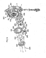
- An exemplary self-retracting lifeline which is not part of the present invention, is designated by the numeral 200 in Figures 8 and 9 .
- self-retracting lifeline Although one type of self-retracting lifeline is shown and described herein for use with the present example, it is recognized that any suitable self-retracting lifeline could be used. Because self-retracting lifelines suitable for use with the present example are well-known, only the components of the self-retracting lifeline 200 relevant to the description of the present example are being described herein.
- the self-retracting lifeline 200 includes a housing 201 defining a cavity 202 having a first compartment 203, a second compartment 204, and a third compartment 206.
- a bore 205 extends at least partially through the housing 201 proximate a middle portion of the second compartment 204.
- the housing 201 also includes a cable exit 207.
- a drum 210 around which a lifeline 245 is wound, is rotatably connected to the housing 201 and fits within the first compartment 203.
- the lifeline 245 includes a first end (not shown) operatively connected to the drum 210, an intermediate portion (not shown) wound about the drum 210, and a second end 248 extending through the cable exit 207 of the housing 201.
- a brake mechanism 211 is operatively connected to the drum 210.
- the brake mechanism 211 includes several components in each of the three compartments.
- a base plate 212 is operatively connected to the drum 210, and brake discs 213 and pawls 214 biased with springs 215 are operatively connected to the base plate 212.
- a gear 218 fits within the first compartment 203 proximate the base plate 212 and includes inner teeth 219 and outer teeth 220.
- a bushing 223 fits within a bore (not shown) of the drum 210 to assist in rotation of the drum 210 about a shaft (not shown).
- a cover 224 is operatively connected to the gear 218 with fasteners 225.
- An isolation disc 222 reduces the friction between the pawls 214 and the cover 224.
- a bushing 226 fits within the bore 205 and a spacer 227 and a gear 228 fit about the bore 205.
- the gear 228 includes inner teeth 229 and outer teeth 230.
- a shaft 231 includes teeth 232a, teeth 232b, and teeth 233 extending outward therefrom proximate an intermediate portion of the shaft 231. The teeth are shown in Figure 9A .
- One end of the shaft 231 extends into the bushing 226 within the bore 205, the teeth 232a mate with the outer teeth 220 of the gear 218, the teeth 232b mate with the inner teeth 229 of the gear 228, and the teeth 233 selectively mate with a mode control assembly (not shown) such as that disclosed in U.S. Patent Application Publication Nos. 2010/0226748A1 and 2010/0224448A1 .
- a disc 235 is positioned proximate the housing and a cylinder 236 is positioned within the third compartment 206.
- the cylinder 236 includes a bore 237 and teeth 238 positioned about the bore 237.
- the teeth 238 mate with the outer teeth 230 of the gear 228.
- Magnets 239 are operatively connected to the cylinder 236, preferably proximate the cylinder's perimeter.
- a fastener 240 extends through the bore 237 and through a bore (not shown) in the housing to rotatably connect the cylinder 236 to the housing 201.
- the disc 235 is used to reduce friction as the cylinder 236 rotates.
- the brake discs 213 are not used to arrest a fall.
- This self-retracting lifeline is shown and described in rescue or descending mode but can be switched to a standard self-retracting lifeline fall arrest mode.
- the standard self-retracting lifeline fall arrest mode uses the brake discs to arrest a fall.
- This type of self-retracting lifeline is known in the art. Examples of this type of self-retracting lifeline are the SEALED-BLOK RSQ and the ULTRA-LOK RSQ by D B Industries, Inc. d/b/a Capital Safety USA of Red Wing, Minnesota. Other examples of this type of self-retracting lifeline are disclosed in U.S. Patent Application Publication Nos. 2010/0226748A1 and 2010/0224448A1 .
- the speed at which the drum 210 rotates is great enough to overcome the biasing force of the springs 215 so that the pawls 214 pivot outward from a disengaged position into an engaged position and at least one of the pawls 214 engages the inner teeth 219 of the gear 218.
- the gear 218 rotates, which causes the shaft 231 to rotate, which causes the gear 228 to rotate, which causes the cylinder 236 to rotate.
- the magnets 239 move relative to the housing 201 and the EMF forces exert a braking force on the drum 210.
- the braking force due to the EMF force generated between the magnets 239 and the housing 201 increases as the rotational velocity increases.
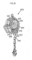
- An exemplary descender that is not part of the present invention is designated by the numeral 300 in Figures 10 and 11 .
- One type of descender that could be used with the present example is the ROLLGLISSTM R500 descender. Although one type of descender is shown and described herein for use with the present example; it is recognized that any suitable descender could be used.
- the descender 300 includes a housing 301 with a base 302 and a cover 312.
- the base 302 defines a cavity 303 and includes a bore 304 proximate the center and a bore 305 proximate the bottom.
- a drum 307 is configured and arranged to fit within the cavity 303 and includes teeth 308 around its perimeter and a shaft 309 extending outward from each side.
- a bushing 306 fits within the bore 304 and a bushing 310 fits within a bore (not shown) in the cover 312. The ends of the shaft 309 are positioned within the bushings 306 and 310.
- the cover 312 defines a cavity 313 and includes a bore 314 proximate the bottom.
- the cover 312 is made from a non-ferromagnetic, electrically conductive material such as aluminum.
- a cylinder 316 is configured and arranged to fit within the cavity 313.
- the cylinder 316 includes magnets 317 proximate its perimeter and a shaft 318 extending outward from each side.
- One end of the shaft 318 fits within a bore (not shown) of a cover (not shown) covering the cavity 313.
- the other end of the shaft 318 extends through the bore 314 of the cover 312 and into a bushing 320 within the bore 305.
- the shaft 318 includes teeth 319 that mate with the teeth 308 of the drum 307.
- a lifeline 325 is operatively connected to the drum 307 by means well known in the art. As tension is placed on the lifeline 325 and the lifeline 325 moves relative to the descender 300, the drum 307 rotates and the cylinder 316 rotates. The magnets 317 of the cylinder 316 interact with the cover 312 and the EMF force provides a braking force on the drum 307 to slow the rate at which the lifeline 325 is paid out. The braking force due to the EMF force generated between the magnets 317 and the cover 312 increases as the rotational velocity increases.
- the self-retracting lifeline 400 is similar to the self-retracting lifeline 200 and includes an additional feature to assist in reducing the retraction speed of the lifeline. Only the components relevant to this additional feature are being described.
- the self-retracting lifelike 400 includes a housing 401, a cover 408, and a drum 410.
- the cover 408 includes magnets 409.
- the magnets 409 shown in Figure 12 show the relative position without the cover 408.
- the magnets could be operatively connected with epoxy or any other suitable adhesive, a fastener, or other suitable connecting means.
- the drum 410 is preferably made from a non-ferromagnetic, electrically conductive material such as aluminum.
- the magnets 409 are positioned on the cover 408 proximate at least one of the sides as far from the drum 410 rotation axis as possible for the greatest effect or other axis-symmetric component of the drum 410.
- the faster the drum 410 rotates the larger the EMF force is on the drum 410 in the opposite direction the drum 410 is rotating. Because the EMF force is in the opposite direction to movement of the drum 410 relative to the magnets 409, a braking force is applied to the drum 410.
- the cover 408 could be made from a non-ferromagnetic, electrically conductive material such as aluminum and the drum 410 could have magnets operatively connected to it so that the magnets interact with the cover as the drum rotates. The movement of the magnets on the drum relative to the cover creates an EMF force to assist in slowing the rate at which the drum 410 rotates.
- the pawls of a self-retracting lifeline are commonly held in an unlocked position with springs, and during the retraction of the lifeline into the housing, the pawls will not typically move into a locking position because they typically only move into the locking position when the drum is rotated at a high enough speed in the direction to payout the lifeline.
- a common problem with self-retracting lifelines is that the pawls can lock at the end of the retraction of the lifeline into the housing if the rotation speed of the drum is high enough and then suddenly stops rotating to cause the pawls to move into a locking position. At the end of the retraction, with a fast spinning drum that suddenly stops, the pawls can be moved into a locking position and will engage the teeth. This causes jamming of the self-retracting lifeline.
- the drum By placing a plurality of magnets proximate the drum (with either the drum including at least one magnet and the cover being at least partially made of a non-ferromagnetic, electrically conductive material such as aluminum or the drum being at least partially made of a non-ferromagnetic, electrically conductive material such.as aluminum and the cover including at least one magnet), as the drum rotates faster, the EMF force between the magnets and the non-ferromagnetic, electrically conductive material increases as the drum rotation speed increases. This provides a braking force on the drum to slow it down. By keeping the rotation speed below the speed at which the pawls pivot to move into the locking position; the self-retracting lifeline should not jam.
Landscapes
- Health & Medical Sciences (AREA)
- General Health & Medical Sciences (AREA)
- Business, Economics & Management (AREA)
- Emergency Management (AREA)
- Engineering & Computer Science (AREA)
- Power Engineering (AREA)
- Emergency Lowering Means (AREA)
- Braking Arrangements (AREA)
Priority Applications (1)
| Application Number | Priority Date | Filing Date | Title |
|---|---|---|---|
| EP14153850.4A EP2777771B1 (en) | 2009-12-23 | 2010-12-23 | Fall Protection Safety Device with a Braking Mechanism |
Applications Claiming Priority (2)
| Application Number | Priority Date | Filing Date | Title |
|---|---|---|---|
| US28955009P | 2009-12-23 | 2009-12-23 | |
| PCT/US2010/062007 WO2011079266A2 (en) | 2009-12-23 | 2010-12-23 | Fall protection safety device with a braking mechanism |
Related Child Applications (2)
| Application Number | Title | Priority Date | Filing Date |
|---|---|---|---|
| EP14153850.4A Division-Into EP2777771B1 (en) | 2009-12-23 | 2010-12-23 | Fall Protection Safety Device with a Braking Mechanism |
| EP14153850.4A Division EP2777771B1 (en) | 2009-12-23 | 2010-12-23 | Fall Protection Safety Device with a Braking Mechanism |
Publications (2)
| Publication Number | Publication Date |
|---|---|
| EP2516020A2 EP2516020A2 (en) | 2012-10-31 |
| EP2516020B1 true EP2516020B1 (en) | 2015-05-27 |
Family
ID=43735787
Family Applications (2)
| Application Number | Title | Priority Date | Filing Date |
|---|---|---|---|
| EP10801071.1A Active EP2516020B1 (en) | 2009-12-23 | 2010-12-23 | Fall protection safety device with a braking mechanism |
| EP14153850.4A Active EP2777771B1 (en) | 2009-12-23 | 2010-12-23 | Fall Protection Safety Device with a Braking Mechanism |
Family Applications After (1)
| Application Number | Title | Priority Date | Filing Date |
|---|---|---|---|
| EP14153850.4A Active EP2777771B1 (en) | 2009-12-23 | 2010-12-23 | Fall Protection Safety Device with a Braking Mechanism |
Country Status (11)
| Country | Link |
|---|---|
| US (1) | US8511434B2 (enExample) |
| EP (2) | EP2516020B1 (enExample) |
| JP (2) | JP5731540B2 (enExample) |
| CN (2) | CN102652029B (enExample) |
| AU (1) | AU2010336378B2 (enExample) |
| BR (1) | BR112012017336A2 (enExample) |
| CA (1) | CA2777855C (enExample) |
| DK (1) | DK2516020T3 (enExample) |
| MX (2) | MX385892B (enExample) |
| SG (1) | SG181479A1 (enExample) |
| WO (1) | WO2011079266A2 (enExample) |
Families Citing this family (55)
| Publication number | Priority date | Publication date | Assignee | Title |
|---|---|---|---|---|
| US8061479B2 (en) * | 2004-04-06 | 2011-11-22 | Harris Jr Rano J | Fall protection system |
| US20150217150A1 (en) * | 2004-04-06 | 2015-08-06 | Downsafe Systems, Llc | Fall protection system |
| US20110220436A1 (en) * | 2008-09-19 | 2011-09-15 | Stephen Green | Fall Protection System |
| NZ575464A (en) | 2009-03-10 | 2010-07-30 | Holmes Solutions Ltd | Improvements in and relating to braking mechanisms |
| US9056753B2 (en) | 2011-10-18 | 2015-06-16 | LynRus Aluminum Products, LLC | Disabling system for auto-arresting safety device |
| USD725831S1 (en) * | 2012-04-24 | 2015-03-31 | Evacuator International Property B.V. | Descent device |
| US9038777B2 (en) * | 2012-10-15 | 2015-05-26 | James F. Stearns Company LLP | Fall protection system |
| CN103007459A (zh) * | 2012-12-04 | 2013-04-03 | 马大勇 | 一种高空作业防坠落装置 |
| NZ619034A (en) * | 2013-12-16 | 2015-03-27 | Eddy Current Ltd Partnership | An assembly to control relative speed of movement between parts |
| CN110838781B (zh) | 2014-08-18 | 2021-12-21 | 涡流有限合伙公司 | 闩锁设备 |
| KR102208367B1 (ko) * | 2014-08-18 | 2021-01-27 | 에디 커런트 리미티드 파트너쉽 | 부재들 사이의 운동학적 관계의 조정 |
| EP4084307B1 (en) | 2014-08-18 | 2025-03-26 | Eddy Current Limited Partnership | Tuning of a kinematic relationship between members |
| CN107206978B (zh) * | 2014-08-20 | 2020-06-02 | 特鲁布鲁有限公司 | 用于旋转系统的涡流制动设备 |
| CN107005140B (zh) | 2014-12-04 | 2020-03-27 | 涡流有限合伙公司 | 包括涡流制动的传动 |
| KR102681482B1 (ko) * | 2014-12-04 | 2024-07-04 | 에디 커런트 리미티드 파트너쉽 | 요소들 사이에서의 래치 활성화 |
| EP4279762B1 (en) * | 2014-12-04 | 2025-08-27 | SureWerx USA, Inc. | Eddy current brake configurations |
| EP3912685A1 (en) | 2014-12-04 | 2021-11-24 | Eddy Current Limited Partnership | Methods of altering eddy current interactions |
| JP6789940B2 (ja) | 2014-12-04 | 2020-11-25 | エディ・カーレント・リミテッド・パートナーシップ | Srl装置およびエネルギーを吸収する方法 |
| DE102015104455B4 (de) * | 2015-03-25 | 2020-11-19 | Lorenz Hasenbach GmbH u. Co KG | Fallschutzläufer und Sicherungssystem mit einem derartigen Fallschutzläufer |
| GB2539418B (en) * | 2015-06-15 | 2019-10-02 | Swisslogo Ag | Self-braking pulley |
| JP7044444B2 (ja) | 2015-12-18 | 2022-03-30 | エディ・カーレント・リミテッド・パートナーシップ | 動力システムのための可変挙動制御機構 |
| US10413761B2 (en) | 2016-03-02 | 2019-09-17 | Msa Technology, Llc | Line retraction device having a damper assembly |
| US10864393B2 (en) | 2016-03-31 | 2020-12-15 | 2Innovate Llc | Fall control system and method of controlling a movement during fall event |
| US10328294B2 (en) * | 2016-04-12 | 2019-06-25 | Msa Technology, Llc | Load indicator for a fall protection apparatus |
| US10022570B2 (en) * | 2016-05-20 | 2018-07-17 | Bailout, LLC | Personal escape device with eddy current braking |
| US10166413B1 (en) | 2016-07-13 | 2019-01-01 | Bailout Systems, Llc | Controlled descent safety systems and methods |
| TWM537490U (zh) * | 2016-09-21 | 2017-03-01 | General Safety Company Ltd | 自動制動的安全裝置 |
| BR112019007569A2 (pt) * | 2016-10-14 | 2019-07-02 | 3M Innovative Properties Co | métodos e aparelhos para gerar energia com o uso de dispositivos de proteção contra quedas |
| GB2556892B (en) * | 2016-11-23 | 2022-04-27 | Latchways Plc | Self-retracting lifeline fall arrest device |
| US10888723B2 (en) | 2017-01-25 | 2021-01-12 | Jeffrey D. Thompson | Self-retracting lanyard with fall protection harness tracker |
| US9852598B1 (en) * | 2017-01-25 | 2017-12-26 | Jeffrey D. Thompson | Swing fall protection device |
| US10722739B2 (en) | 2017-01-25 | 2020-07-28 | Jeffrey D. Thompson | Controlled descent self-retracting lanyard |
| US10792524B2 (en) | 2017-01-25 | 2020-10-06 | Jeffrey D. Thompson | Self-retracting lanyard with fall protection harness tracker |
| KR101889084B1 (ko) * | 2017-03-06 | 2018-08-16 | (주)미디어스페이스 | 추락 체험장치 |
| AU2018248054B2 (en) | 2017-04-03 | 2020-05-07 | 3M Innovative Properties Company | Fall-protection apparatus with protective shroud and with sleeve assembly |
| US11504557B2 (en) | 2017-07-13 | 2022-11-22 | 3M Innovative Properties Company | Fall-protection apparatus comprising friction brake |
| CA3069227A1 (en) * | 2017-07-17 | 2019-01-24 | Safeworks, Llc | Climb assist and fall arrest system |
| US20190338593A1 (en) | 2017-07-17 | 2019-11-07 | Safeworks, Llc | Integrated climb assist and fall arrest systems and methods |
| JP2020529894A (ja) * | 2017-08-10 | 2020-10-15 | スリーエム イノベイティブ プロパティズ カンパニー | 落下抑制デバイスのイベントの生成及び監視 |
| US11524188B2 (en) * | 2018-10-09 | 2022-12-13 | Checkmate Lifting & Safety Ltd | Tensioning device |
| CN109568823B (zh) * | 2018-10-30 | 2021-03-02 | 广东欲丰电器制造有限公司 | 一种缓冲式防坠安全器 |
| US11745035B2 (en) | 2019-01-14 | 2023-09-05 | Msa Technology, Llc | Fall protection compliance system and method |
| US12429494B2 (en) | 2019-01-14 | 2025-09-30 | Msa Technology, Llc | Fall protection compliance system and method |
| US12412464B2 (en) | 2019-01-14 | 2025-09-09 | Msa Technology, Llc | Fall protection compliance system and method |
| US12186596B2 (en) | 2019-09-20 | 2025-01-07 | TruBlue LLC | Lock-off descent control systems and devices |
| US11339610B2 (en) | 2019-09-26 | 2022-05-24 | Alpine Overhead Doors, Inc. | Auxiliary chain assembly for rolling doors and the like |
| CN115348886B (zh) * | 2020-03-18 | 2024-10-15 | 特鲁布鲁有限公司 | 线分配装置 |
| US11534634B2 (en) | 2020-04-03 | 2022-12-27 | Honeywell International Inc. | Brake assembly for fall arrest system |
| WO2022003501A1 (en) | 2020-07-02 | 2022-01-06 | 3M Innovative Properties Company | Fall-protection apparatus comprising braking device with velocity-actuated, acceleration-modulated pawl(s) |
| US11759662B2 (en) | 2020-07-02 | 2023-09-19 | 3M Innovative Properties Company | Fall-protection apparatus comprising dual-actuatable braking device |
| TW202218707A (zh) | 2020-07-10 | 2022-05-16 | 美商3M新設資產公司 | 具有包含攜載撓性型棘爪之制動裝置之墜落防護設備 |
| EP4178683A4 (en) | 2020-07-10 | 2024-04-17 | 3M Innovative Properties Company | FALL PROTECTION DEVICE WITH BRAKE DEVICE WITH FLEXURAL PAWL AND DRUM-MOUNTED STIFFENING |
| US12076594B2 (en) * | 2020-11-23 | 2024-09-03 | Yoke Industrial Corp. | Fall arrester |
| KR102672742B1 (ko) * | 2022-08-09 | 2024-06-05 | 한국전력공사 | 드래그 다운먼트 |
| CN118166672B (zh) * | 2024-05-16 | 2024-07-19 | 山西路桥第六工程有限公司 | 一种桥梁施工防落装置 |
Family Cites Families (27)
| Publication number | Priority date | Publication date | Assignee | Title |
|---|---|---|---|---|
| JPS59217589A (ja) * | 1983-05-26 | 1984-12-07 | 株式会社宮野鉄工所 | 緩降機 |
| JPS60259278A (ja) * | 1984-06-04 | 1985-12-21 | 神鋼電機株式会社 | 渦電流式ブレ−キを使用した降下装置 |
| GB8612945D0 (en) * | 1986-05-28 | 1986-07-02 | Barrow Hepburn Equip Ltd | Safety line drum |
| EP0247818A3 (en) * | 1986-05-28 | 1989-04-05 | Barrow Hepburn Equipment Ltd | Fall-arrest apparatus |
| JPH01256979A (ja) * | 1988-04-05 | 1989-10-13 | Fujii Denko Co Ltd | 無墜落高所作業方法 |
| JPH05155591A (ja) * | 1991-12-06 | 1993-06-22 | Shinko Electric Co Ltd | 電動ウインチ |
| JP2523883Y2 (ja) * | 1992-02-24 | 1997-01-29 | 株式会社三協精機製作所 | プーリ付調速器 |
| JPH07213633A (ja) * | 1994-02-01 | 1995-08-15 | Kazuo Kozutsumi | 回転制御装置及び昇降装置 |
| JPH11192316A (ja) * | 1997-12-26 | 1999-07-21 | Sohken Ohtex Kk | 制動装置 |
| US6397974B1 (en) * | 1998-10-09 | 2002-06-04 | Otis Elevator Company | Traction elevator system using flexible, flat rope and a permanent magnet machine |
| US6293376B1 (en) * | 1999-11-22 | 2001-09-25 | Magnetar Technologies Ltd | Apparatus including eddy current braking system |
| CN2422979Y (zh) * | 2000-04-18 | 2001-03-14 | 周广信 | 声光报警高楼自救逃生索 |
| US7096996B2 (en) * | 2002-07-26 | 2006-08-29 | Pavel V. Korchagin | High-rise fire-fighting, rescue and construction equipment |
| US6830126B2 (en) * | 2003-03-20 | 2004-12-14 | Michael Godwin | Rapid escape system for buildings |
| CN100569615C (zh) * | 2004-05-28 | 2009-12-16 | 三菱电机株式会社 | 电梯的导轨接头检测装置以及电梯装置 |
| EP1919813A1 (en) * | 2005-07-09 | 2008-05-14 | Anthony Cuthbert | Traction arrangements |
| CN2853098Y (zh) * | 2005-09-30 | 2007-01-03 | 温贤胜 | 高空救生器 |
| CN2860528Y (zh) * | 2005-11-11 | 2007-01-24 | 南昌航空工业学院 | 高楼救生器 |
| CN1990064B (zh) * | 2005-12-31 | 2010-08-25 | 白孝林 | 磁阻尼救生器 |
| CN101254330A (zh) * | 2007-03-02 | 2008-09-03 | 项敏 | 一种非机械摩擦阻尼自动控速的方法及其装置 |
| US8272476B2 (en) * | 2007-12-10 | 2012-09-25 | Rapid Egress Descent Systems Ltd. | Descent control device |
| WO2009108041A1 (en) * | 2008-02-25 | 2009-09-03 | M.H. Instructions B.V. | Providing and obtaining first aid assistance in emergency situations |
| ES2382349T3 (es) * | 2008-02-27 | 2012-06-07 | Rapid Vertical Egress System Holding B.V. | Dispositivo de rescate |
| US8141681B2 (en) * | 2008-04-07 | 2012-03-27 | Safeworks, Llc | Tower climbing assist device |
| FR2934342A3 (fr) * | 2008-07-25 | 2010-01-29 | Renault Sas | Dispositif de commande hydraulique d'embrayage et embrayage correspondant. |
| US10688323B2 (en) * | 2009-03-09 | 2020-06-23 | D B Industries, Llc | Safety device with fall arrest and descending modes |
| US9764172B2 (en) | 2009-03-09 | 2017-09-19 | D B Industries, Llc | Safety device with fall arrest and descending modes |
-
2010
- 2010-12-23 CN CN201080056100.6A patent/CN102652029B/zh active Active
- 2010-12-23 CN CN201510025790.3A patent/CN104667444B/zh active Active
- 2010-12-23 JP JP2012546233A patent/JP5731540B2/ja active Active
- 2010-12-23 MX MX2014001258A patent/MX385892B/es unknown
- 2010-12-23 EP EP10801071.1A patent/EP2516020B1/en active Active
- 2010-12-23 EP EP14153850.4A patent/EP2777771B1/en active Active
- 2010-12-23 MX MX2012007436A patent/MX2012007436A/es active IP Right Grant
- 2010-12-23 WO PCT/US2010/062007 patent/WO2011079266A2/en not_active Ceased
- 2010-12-23 US US12/977,526 patent/US8511434B2/en active Active
- 2010-12-23 BR BR112012017336A patent/BR112012017336A2/pt not_active Application Discontinuation
- 2010-12-23 CA CA2777855A patent/CA2777855C/en active Active
- 2010-12-23 AU AU2010336378A patent/AU2010336378B2/en active Active
- 2010-12-23 DK DK10801071.1T patent/DK2516020T3/da active
- 2010-12-23 SG SG2012040572A patent/SG181479A1/en unknown
-
2014
- 2014-02-14 JP JP2014026794A patent/JP5905499B2/ja not_active Expired - Fee Related
Also Published As
| Publication number | Publication date |
|---|---|
| WO2011079266A3 (en) | 2011-08-25 |
| WO2011079266A2 (en) | 2011-06-30 |
| EP2516020A2 (en) | 2012-10-31 |
| CN104667444A (zh) | 2015-06-03 |
| BR112012017336A2 (pt) | 2016-04-19 |
| JP2013515574A (ja) | 2013-05-09 |
| CN104667444B (zh) | 2021-04-27 |
| CN102652029B (zh) | 2015-02-04 |
| JP5731540B2 (ja) | 2015-06-10 |
| MX385892B (es) | 2025-03-18 |
| DK2516020T3 (da) | 2015-06-22 |
| EP2777771A2 (en) | 2014-09-17 |
| MX2012007436A (es) | 2012-07-23 |
| CA2777855A1 (en) | 2011-06-30 |
| EP2777771B1 (en) | 2022-05-04 |
| US8511434B2 (en) | 2013-08-20 |
| CA2777855C (en) | 2013-12-24 |
| JP2014111188A (ja) | 2014-06-19 |
| JP5905499B2 (ja) | 2016-04-20 |
| US20110147125A1 (en) | 2011-06-23 |
| SG181479A1 (en) | 2012-07-30 |
| CN102652029A (zh) | 2012-08-29 |
| AU2010336378A1 (en) | 2012-05-17 |
| EP2777771A3 (en) | 2014-12-24 |
| AU2010336378B2 (en) | 2013-10-10 |
Similar Documents
| Publication | Publication Date | Title |
|---|---|---|
| EP2516020B1 (en) | Fall protection safety device with a braking mechanism | |
| US9080383B2 (en) | Climb assist system | |
| EP2771073B1 (en) | Self-retracting lifeline | |
| US9827451B2 (en) | Height rescue apparatus | |
| EP2958635B1 (en) | Fall arrest device | |
| US4457400A (en) | Emergency descent device | |
| TW202202198A (zh) | 包含具有速度致動加速度調節棘爪的制動裝置之墜落防護設備 | |
| US7097005B2 (en) | Abseiling device | |
| US20030057023A1 (en) | Compact descent controller | |
| CN110745727B (zh) | 电动葫芦和风力发电机 | |
| NZ619680B2 (en) | Height rescue apparatus |
Legal Events
| Date | Code | Title | Description |
|---|---|---|---|
| PUAI | Public reference made under article 153(3) epc to a published international application that has entered the european phase |
Free format text: ORIGINAL CODE: 0009012 |
|
| 17P | Request for examination filed |
Effective date: 20120620 |
|
| AK | Designated contracting states |
Kind code of ref document: A2 Designated state(s): AL AT BE BG CH CY CZ DE DK EE ES FI FR GB GR HR HU IE IS IT LI LT LU LV MC MK MT NL NO PL PT RO RS SE SI SK SM TR |
|
| DAX | Request for extension of the european patent (deleted) | ||
| RAP1 | Party data changed (applicant data changed or rights of an application transferred) |
Owner name: D B INDUSTRIES, LLC |
|
| GRAP | Despatch of communication of intention to grant a patent |
Free format text: ORIGINAL CODE: EPIDOSNIGR1 |
|
| INTG | Intention to grant announced |
Effective date: 20141212 |
|
| GRAS | Grant fee paid |
Free format text: ORIGINAL CODE: EPIDOSNIGR3 |
|
| GRAA | (expected) grant |
Free format text: ORIGINAL CODE: 0009210 |
|
| AK | Designated contracting states |
Kind code of ref document: B1 Designated state(s): AL AT BE BG CH CY CZ DE DK EE ES FI FR GB GR HR HU IE IS IT LI LT LU LV MC MK MT NL NO PL PT RO RS SE SI SK SM TR |
|
| REG | Reference to a national code |
Ref country code: GB Ref legal event code: FG4D |
|
| REG | Reference to a national code |
Ref country code: CH Ref legal event code: EP |
|
| REG | Reference to a national code |
Ref country code: AT Ref legal event code: REF Ref document number: 728517 Country of ref document: AT Kind code of ref document: T Effective date: 20150615 |
|
| REG | Reference to a national code |
Ref country code: SE Ref legal event code: TRGR |
|
| REG | Reference to a national code |
Ref country code: DK Ref legal event code: T3 Effective date: 20150615 |
|
| REG | Reference to a national code |
Ref country code: IE Ref legal event code: FG4D |
|
| REG | Reference to a national code |
Ref country code: DE Ref legal event code: R096 Ref document number: 602010024958 Country of ref document: DE Effective date: 20150709 |
|
| REG | Reference to a national code |
Ref country code: NO Ref legal event code: T2 Effective date: 20150527 |
|
| REG | Reference to a national code |
Ref country code: AT Ref legal event code: MK05 Ref document number: 728517 Country of ref document: AT Kind code of ref document: T Effective date: 20150527 |
|
| REG | Reference to a national code |
Ref country code: LT Ref legal event code: MG4D |
|
| PG25 | Lapsed in a contracting state [announced via postgrant information from national office to epo] |
Ref country code: ES Free format text: LAPSE BECAUSE OF FAILURE TO SUBMIT A TRANSLATION OF THE DESCRIPTION OR TO PAY THE FEE WITHIN THE PRESCRIBED TIME-LIMIT Effective date: 20150527 Ref country code: HR Free format text: LAPSE BECAUSE OF FAILURE TO SUBMIT A TRANSLATION OF THE DESCRIPTION OR TO PAY THE FEE WITHIN THE PRESCRIBED TIME-LIMIT Effective date: 20150527 Ref country code: FI Free format text: LAPSE BECAUSE OF FAILURE TO SUBMIT A TRANSLATION OF THE DESCRIPTION OR TO PAY THE FEE WITHIN THE PRESCRIBED TIME-LIMIT Effective date: 20150527 Ref country code: LT Free format text: LAPSE BECAUSE OF FAILURE TO SUBMIT A TRANSLATION OF THE DESCRIPTION OR TO PAY THE FEE WITHIN THE PRESCRIBED TIME-LIMIT Effective date: 20150527 Ref country code: PT Free format text: LAPSE BECAUSE OF FAILURE TO SUBMIT A TRANSLATION OF THE DESCRIPTION OR TO PAY THE FEE WITHIN THE PRESCRIBED TIME-LIMIT Effective date: 20150928 |
|
| REG | Reference to a national code |
Ref country code: NL Ref legal event code: MP Effective date: 20150527 |
|
| REG | Reference to a national code |
Ref country code: FR Ref legal event code: PLFP Year of fee payment: 6 |
|
| PG25 | Lapsed in a contracting state [announced via postgrant information from national office to epo] |
Ref country code: LV Free format text: LAPSE BECAUSE OF FAILURE TO SUBMIT A TRANSLATION OF THE DESCRIPTION OR TO PAY THE FEE WITHIN THE PRESCRIBED TIME-LIMIT Effective date: 20150527 Ref country code: BG Free format text: LAPSE BECAUSE OF FAILURE TO SUBMIT A TRANSLATION OF THE DESCRIPTION OR TO PAY THE FEE WITHIN THE PRESCRIBED TIME-LIMIT Effective date: 20150827 Ref country code: AT Free format text: LAPSE BECAUSE OF FAILURE TO SUBMIT A TRANSLATION OF THE DESCRIPTION OR TO PAY THE FEE WITHIN THE PRESCRIBED TIME-LIMIT Effective date: 20150527 Ref country code: GR Free format text: LAPSE BECAUSE OF FAILURE TO SUBMIT A TRANSLATION OF THE DESCRIPTION OR TO PAY THE FEE WITHIN THE PRESCRIBED TIME-LIMIT Effective date: 20150828 Ref country code: IS Free format text: LAPSE BECAUSE OF FAILURE TO SUBMIT A TRANSLATION OF THE DESCRIPTION OR TO PAY THE FEE WITHIN THE PRESCRIBED TIME-LIMIT Effective date: 20150927 Ref country code: RS Free format text: LAPSE BECAUSE OF FAILURE TO SUBMIT A TRANSLATION OF THE DESCRIPTION OR TO PAY THE FEE WITHIN THE PRESCRIBED TIME-LIMIT Effective date: 20150527 |
|
| PG25 | Lapsed in a contracting state [announced via postgrant information from national office to epo] |
Ref country code: EE Free format text: LAPSE BECAUSE OF FAILURE TO SUBMIT A TRANSLATION OF THE DESCRIPTION OR TO PAY THE FEE WITHIN THE PRESCRIBED TIME-LIMIT Effective date: 20150527 |
|
| PG25 | Lapsed in a contracting state [announced via postgrant information from national office to epo] |
Ref country code: PL Free format text: LAPSE BECAUSE OF FAILURE TO SUBMIT A TRANSLATION OF THE DESCRIPTION OR TO PAY THE FEE WITHIN THE PRESCRIBED TIME-LIMIT Effective date: 20150527 Ref country code: CZ Free format text: LAPSE BECAUSE OF FAILURE TO SUBMIT A TRANSLATION OF THE DESCRIPTION OR TO PAY THE FEE WITHIN THE PRESCRIBED TIME-LIMIT Effective date: 20150527 Ref country code: RO Free format text: LAPSE BECAUSE OF NON-PAYMENT OF DUE FEES Effective date: 20150527 Ref country code: SK Free format text: LAPSE BECAUSE OF FAILURE TO SUBMIT A TRANSLATION OF THE DESCRIPTION OR TO PAY THE FEE WITHIN THE PRESCRIBED TIME-LIMIT Effective date: 20150527 |
|
| REG | Reference to a national code |
Ref country code: DE Ref legal event code: R097 Ref document number: 602010024958 Country of ref document: DE |
|
| PLBE | No opposition filed within time limit |
Free format text: ORIGINAL CODE: 0009261 |
|
| STAA | Information on the status of an ep patent application or granted ep patent |
Free format text: STATUS: NO OPPOSITION FILED WITHIN TIME LIMIT |
|
| PG25 | Lapsed in a contracting state [announced via postgrant information from national office to epo] |
Ref country code: IT Free format text: LAPSE BECAUSE OF FAILURE TO SUBMIT A TRANSLATION OF THE DESCRIPTION OR TO PAY THE FEE WITHIN THE PRESCRIBED TIME-LIMIT Effective date: 20150527 |
|
| 26N | No opposition filed |
Effective date: 20160301 |
|
| REG | Reference to a national code |
Ref country code: DE Ref legal event code: R082 Ref document number: 602010024958 Country of ref document: DE Representative=s name: HERNANDEZ, YORCK, DIPL.-ING., DE |
|
| PG25 | Lapsed in a contracting state [announced via postgrant information from national office to epo] |
Ref country code: SI Free format text: LAPSE BECAUSE OF FAILURE TO SUBMIT A TRANSLATION OF THE DESCRIPTION OR TO PAY THE FEE WITHIN THE PRESCRIBED TIME-LIMIT Effective date: 20150527 Ref country code: BE Free format text: LAPSE BECAUSE OF NON-PAYMENT OF DUE FEES Effective date: 20151231 |
|
| PG25 | Lapsed in a contracting state [announced via postgrant information from national office to epo] |
Ref country code: LU Free format text: LAPSE BECAUSE OF FAILURE TO SUBMIT A TRANSLATION OF THE DESCRIPTION OR TO PAY THE FEE WITHIN THE PRESCRIBED TIME-LIMIT Effective date: 20151223 Ref country code: MC Free format text: LAPSE BECAUSE OF FAILURE TO SUBMIT A TRANSLATION OF THE DESCRIPTION OR TO PAY THE FEE WITHIN THE PRESCRIBED TIME-LIMIT Effective date: 20150527 |
|
| REG | Reference to a national code |
Ref country code: CH Ref legal event code: PL |
|
| PG25 | Lapsed in a contracting state [announced via postgrant information from national office to epo] |
Ref country code: BE Free format text: LAPSE BECAUSE OF FAILURE TO SUBMIT A TRANSLATION OF THE DESCRIPTION OR TO PAY THE FEE WITHIN THE PRESCRIBED TIME-LIMIT Effective date: 20150527 |
|
| REG | Reference to a national code |
Ref country code: IE Ref legal event code: MM4A |
|
| PG25 | Lapsed in a contracting state [announced via postgrant information from national office to epo] |
Ref country code: IE Free format text: LAPSE BECAUSE OF NON-PAYMENT OF DUE FEES Effective date: 20151223 Ref country code: LI Free format text: LAPSE BECAUSE OF NON-PAYMENT OF DUE FEES Effective date: 20151231 Ref country code: CH Free format text: LAPSE BECAUSE OF NON-PAYMENT OF DUE FEES Effective date: 20151231 |
|
| REG | Reference to a national code |
Ref country code: FR Ref legal event code: PLFP Year of fee payment: 7 |
|
| PG25 | Lapsed in a contracting state [announced via postgrant information from national office to epo] |
Ref country code: HU Free format text: LAPSE BECAUSE OF FAILURE TO SUBMIT A TRANSLATION OF THE DESCRIPTION OR TO PAY THE FEE WITHIN THE PRESCRIBED TIME-LIMIT; INVALID AB INITIO Effective date: 20101223 Ref country code: SM Free format text: LAPSE BECAUSE OF FAILURE TO SUBMIT A TRANSLATION OF THE DESCRIPTION OR TO PAY THE FEE WITHIN THE PRESCRIBED TIME-LIMIT Effective date: 20150527 |
|
| PG25 | Lapsed in a contracting state [announced via postgrant information from national office to epo] |
Ref country code: NL Free format text: LAPSE BECAUSE OF FAILURE TO SUBMIT A TRANSLATION OF THE DESCRIPTION OR TO PAY THE FEE WITHIN THE PRESCRIBED TIME-LIMIT Effective date: 20150527 Ref country code: CY Free format text: LAPSE BECAUSE OF FAILURE TO SUBMIT A TRANSLATION OF THE DESCRIPTION OR TO PAY THE FEE WITHIN THE PRESCRIBED TIME-LIMIT Effective date: 20150527 |
|
| PG25 | Lapsed in a contracting state [announced via postgrant information from national office to epo] |
Ref country code: MT Free format text: LAPSE BECAUSE OF FAILURE TO SUBMIT A TRANSLATION OF THE DESCRIPTION OR TO PAY THE FEE WITHIN THE PRESCRIBED TIME-LIMIT Effective date: 20150527 |
|
| REG | Reference to a national code |
Ref country code: FR Ref legal event code: PLFP Year of fee payment: 8 |
|
| PG25 | Lapsed in a contracting state [announced via postgrant information from national office to epo] |
Ref country code: TR Free format text: LAPSE BECAUSE OF FAILURE TO SUBMIT A TRANSLATION OF THE DESCRIPTION OR TO PAY THE FEE WITHIN THE PRESCRIBED TIME-LIMIT Effective date: 20150527 Ref country code: MK Free format text: LAPSE BECAUSE OF FAILURE TO SUBMIT A TRANSLATION OF THE DESCRIPTION OR TO PAY THE FEE WITHIN THE PRESCRIBED TIME-LIMIT Effective date: 20150527 |
|
| PG25 | Lapsed in a contracting state [announced via postgrant information from national office to epo] |
Ref country code: AL Free format text: LAPSE BECAUSE OF FAILURE TO SUBMIT A TRANSLATION OF THE DESCRIPTION OR TO PAY THE FEE WITHIN THE PRESCRIBED TIME-LIMIT Effective date: 20150527 |
|
| PGFP | Annual fee paid to national office [announced via postgrant information from national office to epo] |
Ref country code: SE Payment date: 20191210 Year of fee payment: 10 Ref country code: NO Payment date: 20191210 Year of fee payment: 10 |
|
| PGFP | Annual fee paid to national office [announced via postgrant information from national office to epo] |
Ref country code: DK Payment date: 20191210 Year of fee payment: 10 |
|
| REG | Reference to a national code |
Ref country code: DK Ref legal event code: EBP Effective date: 20201231 |
|
| REG | Reference to a national code |
Ref country code: NO Ref legal event code: MMEP |
|
| REG | Reference to a national code |
Ref country code: SE Ref legal event code: EUG |
|
| PG25 | Lapsed in a contracting state [announced via postgrant information from national office to epo] |
Ref country code: NO Free format text: LAPSE BECAUSE OF NON-PAYMENT OF DUE FEES Effective date: 20201231 Ref country code: SE Free format text: LAPSE BECAUSE OF NON-PAYMENT OF DUE FEES Effective date: 20201224 |
|
| PG25 | Lapsed in a contracting state [announced via postgrant information from national office to epo] |
Ref country code: DK Free format text: LAPSE BECAUSE OF NON-PAYMENT OF DUE FEES Effective date: 20201231 |
|
| PGFP | Annual fee paid to national office [announced via postgrant information from national office to epo] |
Ref country code: GB Payment date: 20211118 Year of fee payment: 12 Ref country code: FR Payment date: 20211117 Year of fee payment: 12 |
|
| P01 | Opt-out of the competence of the unified patent court (upc) registered |
Effective date: 20230530 |
|
| GBPC | Gb: european patent ceased through non-payment of renewal fee |
Effective date: 20221223 |
|
| PG25 | Lapsed in a contracting state [announced via postgrant information from national office to epo] |
Ref country code: GB Free format text: LAPSE BECAUSE OF NON-PAYMENT OF DUE FEES Effective date: 20221223 |
|
| PG25 | Lapsed in a contracting state [announced via postgrant information from national office to epo] |
Ref country code: FR Free format text: LAPSE BECAUSE OF NON-PAYMENT OF DUE FEES Effective date: 20221231 |
|
| PGFP | Annual fee paid to national office [announced via postgrant information from national office to epo] |
Ref country code: DE Payment date: 20241121 Year of fee payment: 15 |