EP2515044A1 - Système de cuisson - Google Patents
Système de cuisson Download PDFInfo
- Publication number
- EP2515044A1 EP2515044A1 EP12401065A EP12401065A EP2515044A1 EP 2515044 A1 EP2515044 A1 EP 2515044A1 EP 12401065 A EP12401065 A EP 12401065A EP 12401065 A EP12401065 A EP 12401065A EP 2515044 A1 EP2515044 A1 EP 2515044A1
- Authority
- EP
- European Patent Office
- Prior art keywords
- cooking
- door
- camera device
- cooking chamber
- cooking system
- Prior art date
- Legal status (The legal status is an assumption and is not a legal conclusion. Google has not performed a legal analysis and makes no representation as to the accuracy of the status listed.)
- Withdrawn
Links
Images


Classifications
-
- F—MECHANICAL ENGINEERING; LIGHTING; HEATING; WEAPONS; BLASTING
- F24—HEATING; RANGES; VENTILATING
- F24C—DOMESTIC STOVES OR RANGES ; DETAILS OF DOMESTIC STOVES OR RANGES, OF GENERAL APPLICATION
- F24C15/00—Details
- F24C15/02—Doors specially adapted for stoves or ranges
- F24C15/04—Doors specially adapted for stoves or ranges with transparent panels
-
- F—MECHANICAL ENGINEERING; LIGHTING; HEATING; WEAPONS; BLASTING
- F24—HEATING; RANGES; VENTILATING
- F24C—DOMESTIC STOVES OR RANGES ; DETAILS OF DOMESTIC STOVES OR RANGES, OF GENERAL APPLICATION
- F24C7/00—Stoves or ranges heated by electric energy
- F24C7/08—Arrangement or mounting of control or safety devices
- F24C7/082—Arrangement or mounting of control or safety devices on ranges, e.g. control panels, illumination
- F24C7/085—Arrangement or mounting of control or safety devices on ranges, e.g. control panels, illumination on baking ovens
Definitions
- the present invention relates to a cooking system with at least one cooking appliance.
- the present invention also relates to a cooking appliance having at least one cooking chamber and at least one door closing the cooking chamber.
- One difficulty in the insulation of a cooking chamber is, inter alia, the door closing the cooking chamber.
- a large viewing window is provided on the cooking chamber door.
- a user can control the cooking process from the outside through such a viewing window without having to open the cooking chamber door, whereby a substantial part of the heated or heated cooking chamber air would escape from the cooking chamber.
- the thermal insulation of such a door and in particular the viewing window of the door is often not as good as the insulation of the rest of the cooking chamber even in a multi-pane structure.
- cooking appliances with a camera in the cooking chamber have become known. In such cooking devices then captured by a camera images are displayed to a user, for example, on a display.
- a disadvantage of such devices is that at least one additional opening in the cooking chamber limiting Garraummuffel must be present, through which the camera is guided into the oven. Furthermore, additional cooling is often necessary to prevent overheating of the camera. As a result, the energy balance can be deteriorated and there is an increased design effort.
- the viewing aperture of the camera can quickly become dirty or fog due to the fatty vapors produced in the cooking chamber. Then, for the user, the view in the cooking chamber by means of camera and display may be limited or even impossible, so that in turn the cooking chamber door must be opened for visual inspection of the cooking process.
- the cooking system comprises at least one cooking appliance and at least one camera device.
- the cooking appliance has at least one heatable cooking chamber and at least one door closing the cooking chamber.
- the door includes at least one transparent area.
- the at least one camera device can be attached to the door outside the cooking chamber. In this case, the camera device can be mounted on the door in such a way that images from the cooking chamber can be detected through the transparent region.
- different heat sources may be provided on the cooking appliance.
- a user z. B. between top / bottom heat, air recirculation mode, microwave operation or a grill or steam function.
- the different heating functions can be used either individually or in combination with each other.
- the cooking system according to the invention offers many advantages.
- a considerable advantage is that the camera device is arranged in the cold region of the cooking appliance. Because the camera device is arranged outside the cooking chamber, many disadvantages which occur due to the arrangement of a camera device within the cooking chamber can be avoided. For example, no separate opening must be made in the cooking chamber wall through which a camera device is otherwise guided into the cooking chamber. Furthermore, a special cooling can be omitted, which is necessary in conventional cooking appliances to ensure adequate cooling of the camera device.
- the contamination of the camera device in the cooking system according to the invention is considerably lower. Furthermore, the cleaning of the transparent area of the door, through which the camera device can take pictures from the oven, is very simple.
- the cooking system according to the invention proves to be advantageous.
- the door of the cooking appliance of the cooking system has a transparent area through which the camera device can take pictures from the oven. This makes it possible to reduce the transparent area to a minimum. It only has to be possible for the camera device to obtain sufficient visibility into the cooking chamber. By such a configuration, the rest of the door can be optimally insulated, which in comparison to cooking appliances with a large viewing window better energy efficiency of the cooking appliance is achieved.
- the camera device preferably comprises at least one optical unit and at least one processing unit for processing data and in particular image data.
- the processing unit may be e.g. a CCD sensor or other image sensors include or interact with such.
- the optical unit may comprise lens systems of one or more lenses.
- the camera device comprises at least one display device which is suitable and designed to display the captured images.
- a display device the z. B. can be configured as a display, allows to view the images taken from the oven directly to the camera device on the door of the cooking appliance. Thus, a user can be informed on the cooking appliance about the state of the food in the oven.
- the camera device comprises at least one data transmission device.
- This data transmission device can be designed according to various standards. For example, it can be provided as a Bluetooth, WLAN, ANT + or as another data interface, in particular wireless or wireless interface, for wireless data transmission.
- the images recorded from the cooking chamber or the particular digital image data can also be transmitted to other, in particular external devices or to the control electronics of the cooking appliance for controlling cooking processes or cooking processes or to other, in particular external display devices for local display.
- a wired or wired interface can be provided, which establishes a wired connection for controlling the cooking appliance and / or to another device.
- An external device can be, for example, a computer or laptop or a smartphone, to which the image data are transferred for further processing and / or storage there.
- Such an external device may further comprise a display device or cooperate with a display device.
- the camera device is connected to the Internet via the at least one data transmission device.
- the control device of the cooking appliance is designed, evaluate the image data and to obtain additional information such as the size or the instant browning of the food in the oven and preferably compare with information already stored, for example, in a database to also regulate the cooking process based thereon ,
- the camera device is preferably also used as a sensor for cooking appliance control and control.
- the area of the transparent area of the door is less than 50% of the total area of the door and greater than or equal to 0.5 cm 2 .
- the transparent area is designed as a viewing window.
- the viewing window comprises at least two substantially successively arranged and substantially parallel slices.
- At least one of the discs is larger than the transparent region, wherein said at least one disc in particular also has at least one opaque or intransparent section.
- an insulating material may be provided, which is not visible to the user, the disc is particularly easy to clean with its smooth surface from contamination.
- Such a pane having at least one opaque section is preferably provided on the front side of the door and / or on the inside of the door, that is to say on the side of the door facing the cooking space, and in particular extends over the substantially entire area of the respective door side. In the process, such a pane can have an opaque printing in the region of its at least one opaque section, which is applied to the side of the pane facing the door interior.
- a fastening device is provided on the cooking chamber door.
- the fastening device is suitable and designed to secure the camera device at least in sections in front of the transparent area.
- the fastening device comprises a recess in the door, wherein the recess is adapted and adapted to at least partially receive the camera device.
- the recess is adapted and adapted to at least partially receive the camera device.
- a positive reception of the camera device in the recess is preferred, whereby a substantially planar surface of the cooking chamber facing away from the front of the cooking chamber door and the camera device is formed.
- the camera device is designed as a portable computer.
- a portable computer for example, tablet computers, smartphones, laptops or other electronic devices are understood.
- the camera device may be comprised by a portable computer.
- a camera device can be provided particularly simple, which also includes a display device in a device.
- a data transmission device can also be provided in the tablet computer or in the portable computer.
- the especially small dimensions of a tablet computer are particularly well suited to be placed in front of a cooking chamber door.
- At least one illumination device is provided on the cooking chamber.
- the interior of the cooking chamber can be illuminated sufficiently to record with the camera device images from the oven in usable quality.
- the lighting device can be arranged both within the cooking chamber, as well as be provided by the camera device itself. The arrangement of the illumination device on the transparent area may also be advantageous.
- the door closing the cooking chamber has, at least in sections, at least one insulating material.
- the complete isolation of the door is preferred, which is interrupted only in the transparent area. So a particularly good thermal insulation of the oven door can be achieved.
- the cooking appliance according to the invention comprises at least one heatable cooking chamber and at least one door closing the cooking chamber. At least one transparent area is provided on the door.
- the transparent area has an area of less than 50% of the total area of the door and greater than or equal to 0.5 cm 2 .
- the transparent area is for the operation with a arranged outside the cooking chamber camera device suitable and trained.
- Such a cooking appliance offers many advantages.
- a significant advantage is that through the transparent area a viewing window is provided, through which a user can gain insight into the cooking chamber.
- the size of the viewing window is dimensioned such that the insight with the naked eye in the cooking chamber while still possible, that the surface of the viewing window but still as low as possible in order to isolate the rest of the door as well as possible.
- the viewing window In usual cooking chamber doors with a viewing window, the viewing window usually fills the entire surface of the door. As a result, an undesirable loss of heat from the cooking chamber arise because a door with a large viewing window can not be isolated as well as a door without viewing window.
- a camera device can be arranged in front of the transparent area and record images through the transparent area of the oven and display a user to control the cooking process.
- Fig. 1 is shown very schematically in a cooking appliance system 1 according to the invention in a perspective view.
- the cooking appliance system 1 comprises a cooking appliance 50 and a camera device 2.
- the cooking appliance 50 is formed in the embodiment shown here as a hearth 100 and has a hob 17 with four cooking zones 18 in the upper area. Below the hob 17, a control panel 19 is arranged on the various control elements 20 and a display device 21 may be arranged.
- a closable with a door 4 cooking space 3 is provided below the control panel 19 .
- a camera device 2 is arranged, which can take pictures 6 from the cooking chamber 3 and display them on a display device 8 through a transparent region 5, not visible in this figure, in the door 4.
- a user can select 19 different heat sources on the control panel.
- the user z. B. between top / bottom heat, recirculation mode, microwave operation or a grill function.
- the different heating functions can be used either individually or in combination with each other.
- a heating source is not shown in the figures.
- camera device 2 comprises a display device 8, on which one can see the cooking product 22 located in the cooking chamber 3. Furthermore, the camera device 2 for taking pictures 6 from the cooking chamber 3 comprises an image capture device with a processing unit 7 for processing data and in particular image data (cf. Figures 2 . 5 and 7) and expediently an optical unit 28 (cf. FIG. 5 ).
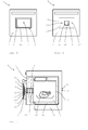
- FIG. 2 an inventive cooking system 1 is shown in a highly simplified side sectional view.
- the cooking appliance 50 which has a housing 23, on which the cooking chamber 3 is arranged.
- the cooking chamber 3 can be closed by a door 4.
- a transparent region 5 is provided, which is designed here as a viewing window 10.
- the viewing window 10 comprises two panes 11.
- the two panes 11 are arranged at a distance from each other substantially parallel to one another.
- a fastening device 12 is provided on the door 4, which in the embodiment shown here has a recess 13 in which the camera device 2 is received.
- the camera device 2 is designed in the embodiment shown here as a portable computer 15, more specifically as a tablet PC 24.
- the tablet PC 24 includes on the cooking chamber 3 side facing an image capture device with a processing unit 7 for processing data and in particular image data through the pictures 6 can be absorbed from the cooking chamber 3.
- the processing unit 7 comprises a CCD sensor, not shown.
- the processing unit 7 may comprise a different type of image sensor, for example a CMOS sensor, or may cooperate with an image sensor.
- the illustrated arrangement of the camera device 2 is very advantageous. Due to the arrangement in the cold region of the cooking appliance 50, ie outside the cooking chamber 3, no additional opening in the cooking chamber 25 must be introduced through which a camera device 2 would otherwise be performed in the cooking chamber 3. The camera device 2 has through the transparent area 5 insight into the cooking chamber.
- the camera device 2 is received flat or flush with the front 14 of the door 4 of the cooking appliance 50 by the fastening device 12. As a result, a particularly beautiful design can be achieved since the camera device 2 does not apply to the door 4 of the cooking appliance 50.
- the cooking chamber 3 surrounds a wall 25, which is also referred to as Garraummuffel, wherein the entire cooking chamber 3 is surrounded by an insulating material 26 in order to avoid heat loss from the cooking chamber 3 as well as possible. Also, the door 4 is substantially completely provided with insulating material 26. The only exception is the transparent region 5 of the door 4, through which the camera device 2 gains insight into the cooking chamber 3.
- the door 4 of a cooking system 1 or a cooking appliance 50 according to the invention is shown.
- a camera device 2 is added to the door 4.
- the camera device 2 comprises a display device 8 and on the rear side an image capture device, not visible from the front and indicated here as a dashed circle, comprising a processing unit 7.
- the images 6 captured or recorded from the cooking chamber 3 can be output on the display device 8.
- Fig. 4 is already in Fig. 3 shown door 4 without camera device 2 shown.
- a transparent area 5 which is arranged approximately in the middle of the door 4.
- a fastening device 12 is provided, which comprises a recess 13 in the embodiment shown here.
- the fastening device 12 two magnets 27 are assigned. These magnets 27 can interact with the rear side of the camera device 2 which is at least partially magnetically embodied in this exemplary embodiment, as a result of which the camera device 2 is stably received in the recess 13.
- Other means for attaching the camera device 2 in front of the transparent area 5 of the door 4, such as latching or clip means can be advantageously used.
- the transparent area 5 shown here is designed as a viewing window 10, which, as already in Fig. 2 described consists of two substantially parallel to each other arranged discs 11.
- the image capture device with the processing unit 7 of the camera device 2 can take pictures 6 from the cooking chamber 3 and display them on the display device 8 of the camera device 2.
- the surface of the viewing window 10 and the viewing area 5 makes up the highest half of the total surface of the door 4.
- the area of the transparent region 5 is also greater than / equal to 0.5 cm 2 . With such a dimensioning of the transparent region 5, it is still possible for a user to get an insight into the cooking chamber 3 even without camera device 2.
- the transparent and thus not insulated with insulating material 26 area 5 is designed so small that overall better insulation of the door 4 can be achieved compared to doors with a large viewing window.
- one or more panes of the door 4 may also be larger than the transparent area and comprise at least one opaque or non-transparent section. This increases the energy efficiency of the cooking appliance 50.
- FIG. 5 a further embodiment of a cooking appliance system 1 according to the invention is shown.
- This cooking system 1 also comprises a cooking device 50 and a camera device 2.
- the cooking device 50 is designed similar to the exemplary embodiment described above.
- the transparent area 5 is again designed as a viewing window 10, in this case a multi-pane structure is made up of three panes 11 arranged essentially parallel to one another.
- the camera device 2 consists in this embodiment of various individual components.
- an image capture device is provided directly in front of the transparent region 5, which includes an optical system 28 and a processing unit 7 with an image chip 29, which is here is designed as a CCD sensor 30 comprises.
- a processing unit 7 with an image chip 29, which is here is designed as a CCD sensor 30 comprises.
- the camera device 2 is not included in a recess 13 in the door 4 in the example shown here, but is applied applying to the cooking chamber facing away from the front side of the door 4.
- the camera device 2 is thereby positioned by a fastening device 12 substantially in front of the transparent region 5, the fastening device 12 comprising two retaining elements 33.
- the fastening device 12 can also be designed differently. Thereby, e.g. Also provided laterally on the camera device 2 holding elements 33, which optimally positioned the camera device 2 or at least their required for image acquisition of individual components in front of the transparent area 5 of the door 4.
- the cooking system 1 shown here includes a cooking appliance 50 and a camera device 2.
- the camera device 2 is again designed as a portable computer 15 here.
- the portable computer 15 is designed as a tablet PC 24, which comprises an image capture device with a processing unit 7, a display device 8 and a data transmission device 9.
- the image capture device is provided on the side facing the cooking chamber 3 of the tablet PC 24 and arranged directly in front of the transparent area 5 of the door 4, so that images 6 can be taken from the cooking chamber 3.
- the images 6 thus captured can then be output on the display device 8.
- the cooking chamber 3 is assigned a lighting device 16, which essentially illuminates the cooking chamber 3.
- the lighting device 16 may also be arranged at other locations in or on the cooking chamber 3.
- the arrangement of the illumination device 16 in the transparent region 5 or the integration of the illumination device 16 into the camera device 2 can also be advantageous.
- the images 6 taken from the cooking chamber 3 can also be transmitted to other display devices 8 via a data transmission device 9.
- the data transmission devices 9 can have different data interface clips 34.
- a wired data interface can be provided, which is connected to another device.
- the recorded images 6 can be transmitted via Bluetooth, WLAN or ANT +.
- the transparent area 5 of the door 4 is also designed here as a viewing window 10.
- three substantially parallel to each other arranged discs 11 are provided, through which the camera device 2 is in visual contact with the cooking chamber 3.
- the transparent region 5 has a substantially cylindrical or conical cross section, with the opening angle of the transparent region 5 becoming larger and larger towards the cooking chamber 3.
- one or more panes of the cooking chamber door can also be larger than the transparent area and comprise at least one opaque or non-transparent section.
- Such a disk preferably extends in particular over the substantially entire surface of the respective door side and may have an opaque printing in the region of its at least one opaque portion, which is then applied to the side of the disk facing the door interior.
Landscapes
- Engineering & Computer Science (AREA)
- Chemical & Material Sciences (AREA)
- Combustion & Propulsion (AREA)
- Mechanical Engineering (AREA)
- General Engineering & Computer Science (AREA)
- Electric Ovens (AREA)
- Electric Stoves And Ranges (AREA)
- Cold Air Circulating Systems And Constructional Details In Refrigerators (AREA)
Applications Claiming Priority (1)
| Application Number | Priority Date | Filing Date | Title |
|---|---|---|---|
| DE201110002187 DE102011002187A1 (de) | 2011-04-20 | 2011-04-20 | Haushaltsgerät |
Publications (1)
| Publication Number | Publication Date |
|---|---|
| EP2515044A1 true EP2515044A1 (fr) | 2012-10-24 |
Family
ID=46084973
Family Applications (1)
| Application Number | Title | Priority Date | Filing Date |
|---|---|---|---|
| EP12401065A Withdrawn EP2515044A1 (fr) | 2011-04-20 | 2012-04-20 | Système de cuisson |
Country Status (2)
| Country | Link |
|---|---|
| EP (1) | EP2515044A1 (fr) |
| DE (1) | DE102011002187A1 (fr) |
Cited By (37)
| Publication number | Priority date | Publication date | Assignee | Title |
|---|---|---|---|---|
| EP2639513A1 (fr) * | 2012-03-16 | 2013-09-18 | BSH Bosch und Siemens Hausgeräte GmbH | Appareil de cuisson |
| WO2014086487A1 (fr) * | 2012-12-04 | 2014-06-12 | Ingo Stork Genannt Wersborg | Dispositif de traitement thermique présentant un système de surveillance |
| DE102013206340A1 (de) * | 2013-04-10 | 2014-10-16 | E.G.O. Elektro-Gerätebau GmbH | Vorrichtung und Verfahren zur Steuerung eines Elektrogeräts |
| EP2930918A1 (fr) * | 2014-04-07 | 2015-10-14 | Indesit Company S.p.A. | Four comprenant une camera |
| WO2015185632A1 (fr) * | 2014-06-05 | 2015-12-10 | BSH Hausgeräte GmbH | Appareil ménager avec chambre de traitement d'aliments et caméra |
| WO2016034295A1 (fr) * | 2014-09-03 | 2016-03-10 | Electrolux Appliances Aktiebolag | Appareil électroménager, en particulier four de cuisson, doté d'une caméra |
| EP3034948A1 (fr) * | 2014-12-19 | 2016-06-22 | Electrolux Appliances Aktiebolag | Porte de four et four comprenant ladite porte |
| WO2017044876A1 (fr) | 2015-09-10 | 2017-03-16 | Brava Home, Inc. | Caméra dans un four |
| EP3263992A1 (fr) * | 2016-06-27 | 2018-01-03 | Electrolux Appliances Aktiebolag | Appareil ménager doté d'un dispositif de contrôle optique |
| CN107735621A (zh) * | 2015-07-03 | 2018-02-23 | 三星电子株式会社 | 烤箱 |
| CN107923627A (zh) * | 2015-07-03 | 2018-04-17 | 三星电子株式会社 | 烤箱 |
| EP3321591A1 (fr) * | 2016-11-15 | 2018-05-16 | Electrolux Appliances Aktiebolag | Dispositif de surveillance pour appareils ménagers et dispositif de maintien |
| WO2018153690A1 (fr) * | 2017-02-21 | 2018-08-30 | BSH Hausgeräte GmbH | Appareil de cuisson doté d'un logement pour un module de détection conçu de manière amovible |
| WO2018153692A1 (fr) * | 2017-02-21 | 2018-08-30 | BSH Hausgeräte GmbH | Appareil de cuisson doté d'un module de détection conçu de manière amovible |
| EP3460336A1 (fr) * | 2017-09-22 | 2019-03-27 | Convotherm Elektrogeräte GmbH | Appareil de cuisson, en particulier appareil de cuisson industriel |
| DE102017125037A1 (de) * | 2017-10-26 | 2019-05-02 | Miele & Cie. Kg | Verfahren und Vorrichtung zum Verarbeiten von Bilddaten eines in einem Haushaltgerät befindlichen Objekts |
| DE102017220887A1 (de) * | 2017-11-22 | 2019-05-23 | BSH Hausgeräte GmbH | Backofen mit Sensoreinrichtung |
| US10440245B1 (en) * | 2018-05-02 | 2019-10-08 | Haier Us Appliance Solutions, Inc. | Oven appliance camera assembly including a light shield |
| US10502430B1 (en) | 2018-10-10 | 2019-12-10 | Brava Home, Inc. | Particulates detection in a cooking instrument |
| US10904951B2 (en) | 2015-09-10 | 2021-01-26 | Brava Home, Inc. | Variable peak wavelength cooking instrument with support tray |
| US11060735B2 (en) | 2015-05-05 | 2021-07-13 | June Life, Inc. | Connected food preparation system and method of use |
| US11116050B1 (en) | 2018-02-08 | 2021-09-07 | June Life, Inc. | High heat in-situ camera systems and operation methods |
| EP3879182A1 (fr) | 2020-03-10 | 2021-09-15 | Electrolux Appliances Aktiebolag | Module de caméra |
| US11156366B2 (en) | 2015-09-10 | 2021-10-26 | Brava Home, Inc. | Dynamic heat adjustment of a spectral power distribution configurable cooking instrument |
| US11206949B1 (en) | 2017-11-15 | 2021-12-28 | Brava Home, Inc. | High power density toaster |
| EP2930433B1 (fr) * | 2014-04-07 | 2022-01-12 | Whirlpool EMEA S.p.A. | Four avec système de balayage |
| US11257394B2 (en) | 2017-08-09 | 2022-02-22 | Brava Home, Inc. | Multizone cooking utilizing a spectral-configurable cooking instrument |
| US11388788B2 (en) | 2015-09-10 | 2022-07-12 | Brava Home, Inc. | In-oven camera and computer vision systems and methods |
| EP4027062A1 (fr) * | 2021-01-11 | 2022-07-13 | LG Electronics Inc. | Appareil de cuisson |
| US11422037B2 (en) | 2018-03-15 | 2022-08-23 | Brava Home, Inc. | Temperature probe systems and methods |
| US11499722B2 (en) | 2020-04-30 | 2022-11-15 | Bsh Home Appliances Corporation | Household cooking appliance having an oven door with an interior camera |
| US11523707B2 (en) | 2015-09-10 | 2022-12-13 | Brava Home, Inc. | Sequential broiling |
| EP4130581A1 (fr) * | 2021-08-03 | 2023-02-08 | BSH Hausgeräte GmbH | Porte d'appareil de cuisson doté d'un module rapporté pour un éclairage ambiant et appareil de cuisson |
| US11593717B2 (en) | 2020-03-27 | 2023-02-28 | June Life, Inc. | System and method for classification of ambiguous objects |
| US11672050B2 (en) | 2017-08-11 | 2023-06-06 | Brava Home, Inc. | Configurable cooking systems and methods |
| US11680712B2 (en) | 2020-03-13 | 2023-06-20 | June Life, Inc. | Method and system for sensor maintenance |
| EP4206542A3 (fr) * | 2021-12-29 | 2023-07-26 | Whirlpool Corporation | Appareil de cuisson comprenant un bloc d'isolation en mousse de verre ou de céramique pour l'isolation de la caméra du four |
Families Citing this family (7)
| Publication number | Priority date | Publication date | Assignee | Title |
|---|---|---|---|---|
| DE102017220886A1 (de) * | 2017-11-22 | 2019-05-23 | BSH Hausgeräte GmbH | Backofen mit Sensoreinrichtung und Lüfter |
| DE102017220889A1 (de) | 2017-11-22 | 2019-05-23 | BSH Hausgeräte GmbH | Backofen mit Sensoreinrichtung |
| DE102017220884A1 (de) | 2017-11-22 | 2019-05-23 | BSH Hausgeräte GmbH | Gargerät mit Bildaufnahmeeinrichtung |
| DE102018217324A1 (de) * | 2018-10-10 | 2020-04-16 | BSH Hausgeräte GmbH | Gargerät mit Kamera und Verfahren zum Betreiben eines Gargeräts |
| CN113614451B (zh) | 2019-04-05 | 2024-03-05 | Bsh家用电器有限公司 | 具有烹饪空间照相机的家用烹饪设备和用于运行的方法 |
| DE102019130443B4 (de) * | 2019-11-12 | 2021-06-10 | Miele & Cie. Kg | Verfahren und System zur Darstellung eines in einem Gargerät durchgeführten Garprozesses |
| EP3872403B1 (fr) | 2020-02-27 | 2024-08-07 | Miele & Cie. KG | Procédé de détermination d'une durée du cycle de nettoyage |
Citations (5)
| Publication number | Priority date | Publication date | Assignee | Title |
|---|---|---|---|---|
| DE4333443A1 (de) * | 1993-09-30 | 1995-04-06 | Bosch Siemens Hausgeraete | Anordnung zur Beobachtung und Überwachung von Garungsvorgängen in Herden |
| WO2009012874A2 (fr) * | 2007-07-24 | 2009-01-29 | BSH Bosch und Siemens Hausgeräte GmbH | Dispositif de préparation d'aliments et de produits de cuisson |
| CN101435601A (zh) * | 2008-12-12 | 2009-05-20 | 申家群 | 无辐射微波炉 |
| WO2009138359A2 (fr) * | 2008-05-13 | 2009-11-19 | BSH Bosch und Siemens Hausgeräte GmbH | Appareil ménager équipé d'un dispositif d'acquisition d'images |
| DE102008043722A1 (de) * | 2008-11-13 | 2010-05-20 | BSH Bosch und Siemens Hausgeräte GmbH | Hausgeräte-Bedienungsanordnung mit einer tragbaren Fernbedienungseinheit |
Family Cites Families (3)
| Publication number | Priority date | Publication date | Assignee | Title |
|---|---|---|---|---|
| US6559882B1 (en) * | 1999-09-02 | 2003-05-06 | Ncr Corporation | Domestic appliance |
| DE20103517U1 (de) * | 2001-02-28 | 2001-05-10 | Rational Ag | Gargerät mit funktionalisierter Gargerätetür |
| KR100793794B1 (ko) * | 2006-04-20 | 2008-01-11 | 엘지전자 주식회사 | 조리기기 |
-
2011
- 2011-04-20 DE DE201110002187 patent/DE102011002187A1/de not_active Ceased
-
2012
- 2012-04-20 EP EP12401065A patent/EP2515044A1/fr not_active Withdrawn
Patent Citations (5)
| Publication number | Priority date | Publication date | Assignee | Title |
|---|---|---|---|---|
| DE4333443A1 (de) * | 1993-09-30 | 1995-04-06 | Bosch Siemens Hausgeraete | Anordnung zur Beobachtung und Überwachung von Garungsvorgängen in Herden |
| WO2009012874A2 (fr) * | 2007-07-24 | 2009-01-29 | BSH Bosch und Siemens Hausgeräte GmbH | Dispositif de préparation d'aliments et de produits de cuisson |
| WO2009138359A2 (fr) * | 2008-05-13 | 2009-11-19 | BSH Bosch und Siemens Hausgeräte GmbH | Appareil ménager équipé d'un dispositif d'acquisition d'images |
| DE102008043722A1 (de) * | 2008-11-13 | 2010-05-20 | BSH Bosch und Siemens Hausgeräte GmbH | Hausgeräte-Bedienungsanordnung mit einer tragbaren Fernbedienungseinheit |
| CN101435601A (zh) * | 2008-12-12 | 2009-05-20 | 申家群 | 无辐射微波炉 |
Cited By (78)
| Publication number | Priority date | Publication date | Assignee | Title |
|---|---|---|---|---|
| EP2639513A1 (fr) * | 2012-03-16 | 2013-09-18 | BSH Bosch und Siemens Hausgeräte GmbH | Appareil de cuisson |
| WO2014086487A1 (fr) * | 2012-12-04 | 2014-06-12 | Ingo Stork Genannt Wersborg | Dispositif de traitement thermique présentant un système de surveillance |
| US20150330640A1 (en) * | 2012-12-04 | 2015-11-19 | Ingo Stork Genannt Wersborg | Heat treatment monitoring system |
| CN105142408A (zh) * | 2012-12-04 | 2015-12-09 | 英戈·施托克格南特韦斯伯格 | 热处理监控系统 |
| US11013237B2 (en) | 2012-12-04 | 2021-05-25 | Ingo Stork Genannt Wersborg | Heat treatment monitoring system |
| CN105142408B (zh) * | 2012-12-04 | 2019-06-11 | 英戈·施托克格南特韦斯伯格 | 热处理监控系统 |
| DE102013206340A1 (de) * | 2013-04-10 | 2014-10-16 | E.G.O. Elektro-Gerätebau GmbH | Vorrichtung und Verfahren zur Steuerung eines Elektrogeräts |
| EP2930918A1 (fr) * | 2014-04-07 | 2015-10-14 | Indesit Company S.p.A. | Four comprenant une camera |
| US10808941B2 (en) | 2014-04-07 | 2020-10-20 | Whirlpool Corporation | Oven comprising a camera |
| US9933165B2 (en) | 2014-04-07 | 2018-04-03 | Whirlpool Emea S.P.A. | Oven comprising a camera |
| EP2930433B1 (fr) * | 2014-04-07 | 2022-01-12 | Whirlpool EMEA S.p.A. | Four avec système de balayage |
| EP3062500A3 (fr) * | 2014-04-07 | 2016-10-05 | Indesit Company S.p.A. | Four comportant une caméra |
| WO2015185632A1 (fr) * | 2014-06-05 | 2015-12-10 | BSH Hausgeräte GmbH | Appareil ménager avec chambre de traitement d'aliments et caméra |
| JP2017527763A (ja) * | 2014-06-05 | 2017-09-21 | ベーエスハー ハウスゲレーテ ゲゼルシャフト ミット ベシュレンクテル ハフツングBSH Hausgeraete GmbH | 食品加工室を備えた家庭用装置およびカメラ |
| CN106465489A (zh) * | 2014-06-05 | 2017-02-22 | Bsh家用电器有限公司 | 具有食物处理室和摄像头的家用器具 |
| US10117294B2 (en) | 2014-06-05 | 2018-10-30 | BSH Hausgeräte GmbH | Household appliance comprising a food processing chamber and camera |
| AU2015311260B2 (en) * | 2014-09-03 | 2020-02-20 | Electrolux Appliances Aktiebolag | Domestic appliance, in particular cooking oven, with a camera |
| US10674569B2 (en) | 2014-09-03 | 2020-06-02 | Electrolux Appliances Aktiebolag | Domestic appliance, in particular cooking oven, with a camera |
| WO2016034295A1 (fr) * | 2014-09-03 | 2016-03-10 | Electrolux Appliances Aktiebolag | Appareil électroménager, en particulier four de cuisson, doté d'une caméra |
| WO2016096550A1 (fr) * | 2014-12-19 | 2016-06-23 | Electrolux Appliances Aktiebolag | Porte de four et four comprenant une porte de four |
| EP3034948A1 (fr) * | 2014-12-19 | 2016-06-22 | Electrolux Appliances Aktiebolag | Porte de four et four comprenant ladite porte |
| US10677474B2 (en) | 2014-12-19 | 2020-06-09 | Electrolux Appliances Aktiebolag | Oven door and oven comprising an oven door |
| US11079117B2 (en) | 2015-05-05 | 2021-08-03 | June Life, Inc. | Connected food preparation system and method of use |
| US11060735B2 (en) | 2015-05-05 | 2021-07-13 | June Life, Inc. | Connected food preparation system and method of use |
| EP3974732A1 (fr) * | 2015-07-03 | 2022-03-30 | Samsung Electronics Co., Ltd. | Four |
| EP3306203A4 (fr) * | 2015-07-03 | 2018-07-11 | Samsung Electronics Co., Ltd. | Four |
| EP3318805A4 (fr) * | 2015-07-03 | 2018-05-30 | Samsung Electronics Co., Ltd. | Four |
| CN107923627A (zh) * | 2015-07-03 | 2018-04-17 | 三星电子株式会社 | 烤箱 |
| US10612789B2 (en) | 2015-07-03 | 2020-04-07 | Samsung Electronics Co., Ltd. | Oven |
| CN107735621A (zh) * | 2015-07-03 | 2018-02-23 | 三星电子株式会社 | 烤箱 |
| US10419647B2 (en) | 2015-07-03 | 2019-09-17 | Samsung Electronics Co., Ltd. | Oven |
| AU2016321324B2 (en) * | 2015-09-10 | 2022-06-02 | Brava Home, Inc. | In-oven camera |
| US10904951B2 (en) | 2015-09-10 | 2021-01-26 | Brava Home, Inc. | Variable peak wavelength cooking instrument with support tray |
| US12035428B2 (en) | 2015-09-10 | 2024-07-09 | Brava Home, Inc. | Variable peak wavelength cooking instrument with support tray |
| US11828658B2 (en) | 2015-09-10 | 2023-11-28 | Brava Home, Inc. | In-oven camera and computer vision systems and methods |
| US11523707B2 (en) | 2015-09-10 | 2022-12-13 | Brava Home, Inc. | Sequential broiling |
| US11388788B2 (en) | 2015-09-10 | 2022-07-12 | Brava Home, Inc. | In-oven camera and computer vision systems and methods |
| WO2017044876A1 (fr) | 2015-09-10 | 2017-03-16 | Brava Home, Inc. | Caméra dans un four |
| EP3347649A4 (fr) * | 2015-09-10 | 2019-05-01 | Brava Home, Inc. | Caméra dans un four |
| CN108474562B (zh) * | 2015-09-10 | 2021-10-29 | 布拉瓦家居公司 | 烤箱内相机 |
| CN108474562A (zh) * | 2015-09-10 | 2018-08-31 | 布拉瓦家居公司 | 烤箱内相机 |
| US10760794B2 (en) | 2015-09-10 | 2020-09-01 | Brava Home, Inc. | In-oven camera |
| US11156366B2 (en) | 2015-09-10 | 2021-10-26 | Brava Home, Inc. | Dynamic heat adjustment of a spectral power distribution configurable cooking instrument |
| WO2018001722A1 (fr) * | 2016-06-27 | 2018-01-04 | Electrolux Appliances Aktiebolag | Appareil ménager muni de dispositif de surveillance optique |
| AU2017290434B2 (en) * | 2016-06-27 | 2022-11-17 | Electrolux Appliances Aktiebolag | Domestic appliance with optical monitoring device |
| EP3263992A1 (fr) * | 2016-06-27 | 2018-01-03 | Electrolux Appliances Aktiebolag | Appareil ménager doté d'un dispositif de contrôle optique |
| US10778876B2 (en) | 2016-06-27 | 2020-09-15 | Electrolux Appliances Aktiebolag | Domestic appliance with optical monitoring device |
| AU2017362676B2 (en) * | 2016-11-15 | 2023-06-15 | Electrolux Appliances Aktiebolag | Monitoring device for household appliances and holding device |
| EP3321591A1 (fr) * | 2016-11-15 | 2018-05-16 | Electrolux Appliances Aktiebolag | Dispositif de surveillance pour appareils ménagers et dispositif de maintien |
| WO2018091369A1 (fr) * | 2016-11-15 | 2018-05-24 | Electrolux Appliances Aktiebolag | Dispositif de surveillance pour appareils ménagers et dispositif de support |
| US11619392B2 (en) | 2016-11-15 | 2023-04-04 | Electrolux Appliances Aktiebolag | Monitoring device for household appliances and holding device |
| CN110291330A (zh) * | 2017-02-21 | 2019-09-27 | Bsh家用电器有限公司 | 带有用于能取出地构造的传感器模块的容纳部的烹饪器具 |
| CN110291331A (zh) * | 2017-02-21 | 2019-09-27 | Bsh家用电器有限公司 | 带有能取出地构造的传感器模块的烹饪器具 |
| WO2018153692A1 (fr) * | 2017-02-21 | 2018-08-30 | BSH Hausgeräte GmbH | Appareil de cuisson doté d'un module de détection conçu de manière amovible |
| US11226105B2 (en) | 2017-02-21 | 2022-01-18 | Bsh Home Appliances Corporation | Cooking appliance comprising a receiving area for a removable sensor module |
| WO2018153690A1 (fr) * | 2017-02-21 | 2018-08-30 | BSH Hausgeräte GmbH | Appareil de cuisson doté d'un logement pour un module de détection conçu de manière amovible |
| US11257394B2 (en) | 2017-08-09 | 2022-02-22 | Brava Home, Inc. | Multizone cooking utilizing a spectral-configurable cooking instrument |
| US11672050B2 (en) | 2017-08-11 | 2023-06-06 | Brava Home, Inc. | Configurable cooking systems and methods |
| EP3460336A1 (fr) * | 2017-09-22 | 2019-03-27 | Convotherm Elektrogeräte GmbH | Appareil de cuisson, en particulier appareil de cuisson industriel |
| US11391466B2 (en) | 2017-09-22 | 2022-07-19 | Welbilt Deutschland GmbH | Cooking appliance, in particular commercial cooking appliance |
| DE102017125037A1 (de) * | 2017-10-26 | 2019-05-02 | Miele & Cie. Kg | Verfahren und Vorrichtung zum Verarbeiten von Bilddaten eines in einem Haushaltgerät befindlichen Objekts |
| US11206949B1 (en) | 2017-11-15 | 2021-12-28 | Brava Home, Inc. | High power density toaster |
| DE102017220887A1 (de) * | 2017-11-22 | 2019-05-23 | BSH Hausgeräte GmbH | Backofen mit Sensoreinrichtung |
| US11765798B2 (en) | 2018-02-08 | 2023-09-19 | June Life, Inc. | High heat in-situ camera systems and operation methods |
| US11116050B1 (en) | 2018-02-08 | 2021-09-07 | June Life, Inc. | High heat in-situ camera systems and operation methods |
| US11422037B2 (en) | 2018-03-15 | 2022-08-23 | Brava Home, Inc. | Temperature probe systems and methods |
| US10440245B1 (en) * | 2018-05-02 | 2019-10-08 | Haier Us Appliance Solutions, Inc. | Oven appliance camera assembly including a light shield |
| US10502430B1 (en) | 2018-10-10 | 2019-12-10 | Brava Home, Inc. | Particulates detection in a cooking instrument |
| EP3879182A1 (fr) | 2020-03-10 | 2021-09-15 | Electrolux Appliances Aktiebolag | Module de caméra |
| WO2021180554A1 (fr) | 2020-03-10 | 2021-09-16 | Electrolux Appliances Aktiebolag | Module de caméra |
| US12050015B2 (en) | 2020-03-13 | 2024-07-30 | June Life, Llc | Method and system for sensor maintenance |
| US11680712B2 (en) | 2020-03-13 | 2023-06-20 | June Life, Inc. | Method and system for sensor maintenance |
| US11593717B2 (en) | 2020-03-27 | 2023-02-28 | June Life, Inc. | System and method for classification of ambiguous objects |
| US11748669B2 (en) | 2020-03-27 | 2023-09-05 | June Life, Inc. | System and method for classification of ambiguous objects |
| US11499722B2 (en) | 2020-04-30 | 2022-11-15 | Bsh Home Appliances Corporation | Household cooking appliance having an oven door with an interior camera |
| EP4027062A1 (fr) * | 2021-01-11 | 2022-07-13 | LG Electronics Inc. | Appareil de cuisson |
| EP4130581A1 (fr) * | 2021-08-03 | 2023-02-08 | BSH Hausgeräte GmbH | Porte d'appareil de cuisson doté d'un module rapporté pour un éclairage ambiant et appareil de cuisson |
| EP4206542A3 (fr) * | 2021-12-29 | 2023-07-26 | Whirlpool Corporation | Appareil de cuisson comprenant un bloc d'isolation en mousse de verre ou de céramique pour l'isolation de la caméra du four |
Also Published As
| Publication number | Publication date |
|---|---|
| DE102011002187A1 (de) | 2012-10-25 |
Similar Documents
| Publication | Publication Date | Title |
|---|---|---|
| EP2515044A1 (fr) | Système de cuisson | |
| EP3586064B1 (fr) | Appareil de cuisson doté d'un module de détection conçu de manière amovible | |
| DE202008000135U1 (de) | Vorrichtung zum Herstellen von Speisen oder Backwaren | |
| DE102008042804A1 (de) | Gargerät mit Kamera | |
| EP2637476B1 (fr) | Champ de cuisson | |
| EP0646753A2 (fr) | Regard de porte à isolation thermique pour appareil à température différente de la température ambiante | |
| DE102018217324A1 (de) | Gargerät mit Kamera und Verfahren zum Betreiben eines Gargeräts | |
| DE202011002570U1 (de) | Vorrichtung zur automatischen Wärmebehandlung von Lebensmitteln | |
| DE19705697C2 (de) | Haushaltsherd mit einer auf Glas abgedichteten Muffel | |
| WO2007080036A1 (fr) | Agencement double d'appareils ménagers | |
| DE102020207425A1 (de) | Haushaltsgerät | |
| DE4333443A1 (de) | Anordnung zur Beobachtung und Überwachung von Garungsvorgängen in Herden | |
| DE3015286A1 (de) | Back- und/oder brateinrichtung | |
| DE102011103300A1 (de) | Geschlossenes Kühlregal | |
| DE102018201743A1 (de) | Gargerät, insbesondere gewerbliches Gargerät | |
| WO1999024759A2 (fr) | Porte de regard pour appareil a temperature interieure elevee | |
| CH697480B1 (de) | Garofen. | |
| DE19809761A1 (de) | Gargerät mit pyrolytischer Selbstreinigung | |
| DE102014201643A1 (de) | Haushaltsgerät mit bistabiler Anzeigeeinrichtung | |
| DE102006001249A1 (de) | Gerätetür und Haushaltsgerät mit der Gerätetür | |
| DE102017216855A1 (de) | Gargerät, insbesondere gewerbliches Gargerät | |
| DE10256276B3 (de) | Wandung eines Küchengerätes | |
| WO2018094429A1 (fr) | Système de régulation d'une opération de cuisson | |
| BE1029164B1 (de) | Einbauküchengerät | |
| DE10234546A1 (de) | Herd |
Legal Events
| Date | Code | Title | Description |
|---|---|---|---|
| PUAI | Public reference made under article 153(3) epc to a published international application that has entered the european phase |
Free format text: ORIGINAL CODE: 0009012 |
|
| AK | Designated contracting states |
Kind code of ref document: A1 Designated state(s): AL AT BE BG CH CY CZ DE DK EE ES FI FR GB GR HR HU IE IS IT LI LT LU LV MC MK MT NL NO PL PT RO RS SE SI SK SM TR |
|
| AX | Request for extension of the european patent |
Extension state: BA ME |
|
| STAA | Information on the status of an ep patent application or granted ep patent |
Free format text: STATUS: THE APPLICATION IS DEEMED TO BE WITHDRAWN |
|
| 18D | Application deemed to be withdrawn |
Effective date: 20130425 |