EP2511930A1 - Temperaturschutzschalter - Google Patents
Temperaturschutzschalter Download PDFInfo
- Publication number
- EP2511930A1 EP2511930A1 EP12160468A EP12160468A EP2511930A1 EP 2511930 A1 EP2511930 A1 EP 2511930A1 EP 12160468 A EP12160468 A EP 12160468A EP 12160468 A EP12160468 A EP 12160468A EP 2511930 A1 EP2511930 A1 EP 2511930A1
- Authority
- EP
- European Patent Office
- Prior art keywords
- spring
- insulator body
- leg
- circuit breaker
- housing
- Prior art date
- Legal status (The legal status is an assumption and is not a legal conclusion. Google has not performed a legal analysis and makes no representation as to the accuracy of the status listed.)
- Granted
Links
- 230000001681 protective effect Effects 0.000 title 1
- 239000012212 insulator Substances 0.000 claims abstract description 44
- 229910000831 Steel Inorganic materials 0.000 claims description 3
- 239000010959 steel Substances 0.000 claims description 3
- 239000003302 ferromagnetic material Substances 0.000 claims description 2
- 230000037431 insertion Effects 0.000 abstract 1
- 238000003780 insertion Methods 0.000 abstract 1
- 210000002414 leg Anatomy 0.000 description 21
- 238000011161 development Methods 0.000 description 10
- 230000018109 developmental process Effects 0.000 description 10
- 239000002184 metal Substances 0.000 description 5
- 238000010276 construction Methods 0.000 description 3
- 238000010438 heat treatment Methods 0.000 description 3
- 230000008878 coupling Effects 0.000 description 2
- 238000010168 coupling process Methods 0.000 description 2
- 238000005859 coupling reaction Methods 0.000 description 2
- 239000012777 electrically insulating material Substances 0.000 description 2
- 230000005291 magnetic effect Effects 0.000 description 2
- 238000004519 manufacturing process Methods 0.000 description 2
- 238000004026 adhesive bonding Methods 0.000 description 1
- 239000011324 bead Substances 0.000 description 1
- 239000000919 ceramic Substances 0.000 description 1
- 239000004020 conductor Substances 0.000 description 1
- 238000002788 crimping Methods 0.000 description 1
- 238000005520 cutting process Methods 0.000 description 1
- 230000001419 dependent effect Effects 0.000 description 1
- 230000000694 effects Effects 0.000 description 1
- 238000005538 encapsulation Methods 0.000 description 1
- 230000005294 ferromagnetic effect Effects 0.000 description 1
- 239000000463 material Substances 0.000 description 1
- 238000013021 overheating Methods 0.000 description 1
- 230000001012 protector Effects 0.000 description 1
- 210000000689 upper leg Anatomy 0.000 description 1
- 238000003466 welding Methods 0.000 description 1
Images


Classifications
-
- H—ELECTRICITY
- H01—ELECTRIC ELEMENTS
- H01H—ELECTRIC SWITCHES; RELAYS; SELECTORS; EMERGENCY PROTECTIVE DEVICES
- H01H37/00—Thermally-actuated switches
- H01H37/02—Details
- H01H37/32—Thermally-sensitive members
- H01H37/52—Thermally-sensitive members actuated due to deflection of bimetallic element
- H01H37/54—Thermally-sensitive members actuated due to deflection of bimetallic element wherein the bimetallic element is inherently snap acting
- H01H37/5427—Thermally-sensitive members actuated due to deflection of bimetallic element wherein the bimetallic element is inherently snap acting encapsulated in sealed miniaturised housing
-
- H—ELECTRICITY
- H01—ELECTRIC ELEMENTS
- H01H—ELECTRIC SWITCHES; RELAYS; SELECTORS; EMERGENCY PROTECTIVE DEVICES
- H01H37/00—Thermally-actuated switches
- H01H37/02—Details
- H01H37/64—Contacts
Definitions
- the invention relates to a temperature protection switch with the features specified in the preamble of claim 1.
- Such a temperature protection switch is used to protect electrical equipment, motors, transformers and the like from overheating. It should open when the temperature at its place of use exceeds a predetermined limit. This limit is hereinafter referred to as the switching temperature.
- the switching temperature is dictated by a bimetallic disc, which can not change its shape or curvature continuously, but only by leaps and bounds, when a minimum mechanical stress determined by the shape of the bimetallic disc and by its elastic properties has built up by temperature change in the bimetallic disc. For safety reasons, tolerance limits specified for the switching temperature must be observed.
- a temperature protection switch with the features specified in the preamble of claim 1 is known from DE 195 09 656 C2 known.
- the bimetallic disc carries the movable contact. When the switch is closed, the current therefore flows over the bimetallic disc. In this case, heat is generated in the bimetal disc, which depends on the current intensity and the ohmic resistance of the bimetallic disc. This is disadvantageous for some applications, because a temperature can be faked by the current heat generated in the contact spring, which is higher than the temperature at the location to be monitored of the electrical device. It may therefore come to unwanted tripping of the bimetallic switch.
- a temperature protection switch with an improved current carrying capacity is known in which the bimetallic disc carries a contact bridge which connects a fixed contact of the first terminal plate electrically conductively connected to a fixed contact of the second terminal plate with the switch closed.
- the switch When the switch is closed, the current therefore no longer flows through the bimetal disc, but instead through the contact bridge, which has a much lower electrical resistance.
- This switch can therefore carry much higher electrical currents before ohmic heat loss leads to an opening of the switch.
- a temperature protection switch for high currents is also from the DE 10 2008 048 554 B3 known.
- This switch has a flat insulator body, which carries a connecting plate on its top and bottom.
- the movable contact is electrically connected via a leaf spring with one of the two connection plates.
- a bimetallic disc In a recess of the insulator body is a bimetallic disc, against which a buckling of the leaf spring. When snapping the bimetallic disc lifts the leaf spring, so that the attached to the leaf spring movable contact lifts from the fixed contact. Similar to the one from the EP 1 774 555 B1 Thus, the current does not flow through the bimetal disc, so that the permissible currents are not limited by the electrical resistance of the bimetal disc.
- a temperature protection switch is known in which the connection plates are attached to the outside of a cup-shaped insulator and over each a rivet are connected to a contact inside the insulator.
- One of the two contacts is formed as a fixed contact, which is arranged on a side wall of the cup-shaped insulator.
- the fixed contact cooperates with a movable contact, which is connected via a U-shaped spring bent electrically connected to the rivet of the second connection plate.
- On the spring leg, which carries the movable contact loads a plunger, which is passed through a block-shaped insulator closing block and is moved by a bimetallic disc, which is arranged outside of the cup-shaped insulator body in a metal housing. When the sound temperature is exceeded, the bimetal disc presses the two legs of the contact spring together, so that the movable contact is lifted from the fixed contact.
- Object of the present invention is to show a way to realize a compact thermal circuit breaker, which shows a reliable switching behavior, which is largely unaffected by the current generated in the thermal circuit breaker heat.
- the current flows through a contact spring, which carries the movable contact on a first leg and contacts the second connection plate with a second leg. Between the first leg of the spring and the bimetallic disc, a plunger is arranged, the bimetallic disc when the switching temperature is exceeded against the first leg presses and so lifts the movable contact from the fixed contact.
- the construction according to the invention makes possible a compact temperature protection switch which can also be used with high electrical powers, for example for currents of more than 10 A at a mains voltage of 230 V.
- a temperature protection switch according to the invention has the following advantages over known thermal circuit breakers:
- the current carrying capacity of a switch according to the invention is higher than that of the DE 10 2008 048 554 B3 known switch, since the bimetallic disc is arranged at a greater distance from the contact spring. A heating of the contact spring that is unavoidable at higher currents therefore has a significantly less effect on the bimetallic disk.
- the bimetallic disc of a thermal circuit breaker according to the invention is even less affected by the heat loss of a current flowing through the switch.
- the disadvantage of the DE 10 2008 048 554 B3 overcome known switches that the bimetallic disc is thermally insulated from the environment inside the insulator body and the known switch therefore reacts only very slowly to changes in ambient temperature.
- a temperature protection switch according to the invention advantageously has a construction which is as flat as that of FIG DE 195 09 656 C2 known temperature protection switch.
- the current carrying capacity of a switch according to the invention is substantially greater, since heating of the bimetallic disc is avoided by ohmic heat loss.
- the current carrying capacity of a switch according to the invention is as good as the current carrying capacity of the from DE 31 36 312 A1 known switch.
- a switch according to the invention has a much more compact construction and can be produced more easily.
- the pot-shaped housing of the known thermal circuit breaker has namely a considerable height result that makes a use for the protection of electric motors practically impossible.
- the known switch consists of a very large number of items that must be joined together in a large number of complex manufacturing steps.
- the connection plates and the contact spring must be firmly riveted to the cup-shaped insulator and the metal washer must be secured to the cup-shaped insulator with a dish-shaped metal casing.
- An advantageous development of the present invention provides that the two legs of the spring for opening the switch are bent apart from the plunger.
- the first leg of the spring which carries the movable contact, ie away from the second leg.
- the spring of a thermal circuit breaker according to the invention is thus claimed on the opening of the switch to train, while in contrast to the legs of the contact spring in which from the DE 31 36 312 A1 known temperature protection switch to open the switch of the plunger are pressed together.
- the inventive measure that the two legs of the spring to open the switch are bent apart from the plunger, allows a particularly compact design of the thermal circuit breaker.
- a further advantageous development of the invention provides that the spring is fastened to the second connection plate with a section which extends transversely to the longitudinal direction of the two spring legs. In this way, the spring can be arranged compactly between the two connecting plates.
- the insulator body is composed of two sub-bodies, wherein the two connecting plates are located between the sub-bodies.
- the connection plates can be inserted together with the spring and the two contacts in a first part body.
- a second part body made of an electrically insulating material, preferably made of plastic, placed on the contact plates on the contact plates.
- the two body parts can be positively connected with each other, for example, by crimping or latching, non-positively, for example, by jamming or hot stamping, or are materially connected, for example, glued or welded.
- the two partial bodies can also be held together, for example, by the pushed-on housing become.
- a further advantageous development of the invention provides that the bimetal disc is seated on the outside of the insulator body.
- the temperature of the bimetallic disc nourishes in this way as far as possible to the ambient temperature of the thermal circuit breaker and remains largely unaffected by heat loss of the current flowing through the thermal circuit breaker current.
- the bimetallic disc sits in a recess on the outside of the insulator body. In this way, it is advantageous to facilitate the assembly of the temperature protection switch.
- the housing has an upper side and a lower side, which are connected to one another via narrow sides.
- a housing is flat, which is an important advantage in using the thermal protector to protect motors and similar equipment.
- the housing is open at one of its narrow sides and attached with this side to the insulator body.
- the housing elongated. The extending in the longitudinal direction of the housing narrow sides then have a greater length than the transverse to the longitudinal direction extending housing opening.
- a further advantageous development of the present invention provides that a portion of the insulator body protrudes from the housing, for example, the insulator body form a stop for the housing.
- a portion of the spring is arranged in a protruding from the housing portion. It is particularly preferred that a bent portion of the spring, which connects the two spring legs, arranged in the protruding from the housing portion of the insulator body. This means that a cutting plane defined by the housing opening passes through the spring.
- the insulator body has on a front side, from which protrude the terminal plates, a protruding portion which lies between the connecting plates. Prefers lies in this section of the bent portion of the spring, which connects the two spring legs
- a further advantageous development of the present invention provides that the housing is made of a ferromagnetic material, for example of steel. In this way, a magnetic shield can advantageously be achieved by simple means.
- a further advantageous development of the present invention provides that the plunger protrudes between the two connecting plates when the switch is open. Preferably, the plunger protrudes between the terminal plates even when the switch is closed.
- the fixed contact can be formed in a temperature protection switch according to the invention of the first terminal plate.
- the fixed contact is a separate component which is fastened on the connection plate.
- the in the FIGS. 1 to 4 illustrated thermal circuit breaker has a first terminal plate 1, which carries a fixed contact 2, and a second terminal plate 3, which is electrically connected via a spring 4 with a movable contact 5.
- the connection plates 1, 3 are in the FIGS. 1 and 3 shown as a one-piece stamped part. After assembly, the connection plates 1, 3 are separated by a connecting the connecting plates web is removed.
- the fixed contact 2 can be attached to the first connection plate 1, for example by welding or riveting.
- the preferably U-shaped bent spring 4 can be welded or riveted to the movable contact 5 and to the second connecting plate 3.
- the connection plates 1, 3 and the contacts 2, 5 and the spring 4 can be pre-assembled into an assembly.
- the connection plates 1, 3 can still be formed as a common component, as in FIG. 1 is shown. In particular FIG. 3 shows, the spring 4 is arranged over a gap between the two terminal plates 1, 3.
- connection plates 1, 3 protrude out of an insulator body, which is composed of two part bodies 6a, 6b.
- the two partial bodies 6a, 6b consist of an electrically insulating material, for example of plastic.
- the first part body 6a forms a receptacle for the connection plates 1, 3, which is then closed by the second part body 6b.
- a bimetallic disc 7 On the outside of the insulator body, preferably in a recess of the first part body 6a, a bimetallic disc 7 is arranged, which separates a conductive connection between the two connection plates 1, 3 when a switching temperature is exceeded.
- the bimetallic disc 7 acts via a plunger 8 on the contact spring 4, which projects between the two connection plates 1, 3 passes.
- the plunger 8 is arranged in a channel of the first part body 6a.
- the plunger 8 is pressed by the bimetallic disc 7 against the first leg 4 a of the contact spring 4, which carries the movable contact 5.
- the first leg 4 a of the second leg 4 b which rests against the second connection plate 3, bent away.
- the two legs 4a, 4b of the spring 4 to open the temperature protection switch from the plunger 8 are bent apart.
- the contact spring 4 is So a bow spring, which is bent to open the thermal circuit breaker.
- the bimetallic disc 7 is held in the recess of an outer side of the first part body 6 a by a ring 9.
- the ring 9 is preferably made of metal, since so the thermal coupling of the bimetallic disc 7 is improved to the environment of the switch.
- the ring 9 covers the edge of the bimetallic disc 7 and can be attached to the part body 6a of the insulator body, for example by gluing or clamping, for example by hot stamping.
- the bimetallic disc 7 is in the illustrated embodiment on a bead of the insulator body. In this way, the contact surface between bimetallic disc 7 and insulator body can thus minimize the heat coupling of the bimetallic disc.
- the insulator body 6a, 6b is inserted into a housing 10 after assembly.
- the housing 10 is a flat housing cap.
- the housing 10 thus has a top and a bottom, which are connected by narrow sides. On one of the narrow sides of the housing 10 is open, so that in this end of the preferably elongated housing 10 of the insulator body 6a, 6b can be inserted.
- the terminal plates 1, 3 project with one end out of the housing 10.
- Fig. 4 shows, the insulator body 6a, 6b protrudes from the housing 10.
- a portion of the spring 4 is arranged, namely the two spring legs 4a, 4b connecting bent portion. The spring 4 is thus only partially arranged in the housing 10.
- connection plates 1, 3 protrude from an end face of the insulator body 6a, 6b.
- At the front side of the insulator body 6a, 6b has a protruding portion which lies between the two connecting plates. This projecting portion protrudes from the housing 10 and contains the bent portion of the spring 4, which connects the two spring legs.
- the housing 10 may be made of ferromagnetic metal, such as steel, to magnetically shield the derailleur of the thermal circuit breaker. This is for example when using the temperature protection switch important for electric motors or transformers, since in such applications typically strong magnetic fields occur.
- the bimetal disc 7 is preferably a circular disc, but may also have a different shape and be formed for example as an elongated strip.
- FIG. 5 shows an exploded view of another embodiment of a thermal circuit breaker.
- This embodiment differs from the embodiment described above substantially only in that a self-holding function of the switch has been added.
- This self-holding function causes enough heat to be produced after opening the switch to prevent the switch from automatically closing.
- a resistor 11 preferably a ceramic resistor, such as a PTC resistor, is provided, which connects the two terminal plates 1, 3 electrically conductive with each other.
- the resistor 11 can be pressed by a leaf spring 12 against the two connecting plates 1, 3.
- An electrical resistance for a self-holding function for example, outside of the housing, for example, on a protruding from the housing opening end face of the insulator body 6a, 6b are arranged. It is also possible to form the insulator body 6a, 6b as an electrical resistance for a self-holding function. In this case, the insulator body 6a, 6b or at least one of the two body parts 6a, 6b, a poor insulator or a bad electrical conductor, so that when the switch is open by the insulator body flows a current that generates sufficient heat loss to cool the To prevent bimetallic disc 7 below its switching temperature.
Abstract
Description
- Die Erfindung geht aus von einem Temperaturschutzschalter mit den im Oberbegriff des Anspruchs 1 angegebenen Merkmalen.
- Ein solcher Temperaturschutzschalter dient dem Schutz von elektrischen Geräten, Motoren, Transformatoren und dergleichen vor Überhitzung. Er soll öffnen, wenn die Temperatur an seinem Einsatzort einen vorgegebenen Grenzwert übersteigt. Dieser Grenzwert wird nachfolgend als die Schalttemperatur bezeichnet. Die Schalttemperatur wird durch eine Bimetallscheibe vorgegeben, die ihre Gestalt bzw. Krümmung nicht stetig ändern kann, sondern nur sprunghaft, wenn sich durch Temperaturänderung in der Bimetallscheibe eine von der Gestalt der Bimetallscheibe und von ihren elastischen Eigenschaften bestimmte mechanische Mindestspannung aufgebaut hat. Aus Sicherheitsgründen sind für die Schalttemperatur vorgegebene Toleranzgrenzen einzuhalten.
- Ein Temperaturschutzschalter mit den im Oberbegriff des Anspruchs 1 angegebenen Merkmalen ist aus der
DE 195 09 656 C2 bekannt. Bei dem bekannten Schalter trägt die Bimetallscheibe den beweglichen Kontakt. Bei geschlossenem Schalter fließt der Strom deshalb über die Bimetallscheibe. Dabei wird in der Bimetallscheibe Wärme erzeugt, die von der Stromstärke und dem ohmschen Widerstand der Bimetallscheibe abhängt. Diese ist für manche Anwendungen nachteilig, weil durch die in der Kontaktfeder erzeugte Stromwärme eine Temperatur vorgetäuscht werden kann, welche höher ist als die Temperatur an dem zu überwachenden Einsatzort des elektrischen Geräts. Es kann deshalb zu unterwünschten Auslösungen des Thermobimetallschalters kommen. - Aus der
EP 1 774 555 B1 ist ein Temperaturschutzschalter mit einer verbesserten Stromtragfähigkeit bekannt, bei dem die Bimetallscheibe eine Kontaktbrücke trägt, die bei geschlossenem Schalter einen Festkontakt des ersten Anschlussblechs elektrisch leitend mit einem Festkontakt des zweiten Anschlussblechs verbindet. Bei geschlossenem Schalter fließt der Strom deshalb nicht mehr durch die Bimetallscheibe, sondern stattdessen durch die Kontaktbrücke, die einen wesentlich geringeren elektrischen Widerstand hat. Dieser Schalter kann deshalb wesentlich höhere elektrische Ströme tragen, bevor ohmsche Verlustwärme zu einem Öffnen des Schalters führt. - Ein Temperaturschutzschalter für hohe Ströme ist auch aus der
DE 10 2008 048 554 B3 bekannt. Dieser Schalter hat einen flachen Isolatorkörper, der auf seiner Oberseite und seiner Unterseite jeweils ein Anschlussblech trägt. Der bewegliche Kontakt ist über eine Blattfeder elektrisch leitend mit einem der beiden Anschlussbleche verbunden. In einer Aussparung des Isolatorkörpers liegt eine Bimetallscheibe, an der eine Ausbeulung der Blattfeder anliegt. Beim Umschnappen hebt die Bimetallscheibe die Blattfeder an, so dass sich der an der Blattfeder befestigte bewegliche Kontakt von dem Festkontakt abhebt. Ähnlich wie bei dem aus derEP 1 774 555 B1 bekannten Schalter fließt der Strom also nicht durch die Bimetallscheibe, so dass die zulässigen Ströme nicht durch den elektrischen Widerstand der Bimetallscheibe begrenzt sind. - Aus der
DE 31 36 312 A1 ist ein Temperaturschutzschalter bekannt, bei dem die Anschlussbleche außen an einem topfförmigen Isolator befestigt sind und jeweils über einen Niet mit einem Kontakt im Inneren des Isolators verbunden sind. Einer der beiden Kontakte ist als ein Festkontakt ausgebildet, der an einer Seitenwand des topfförmigen Isolators angeordnet ist. Der Festkontakt wirkt mit einem beweglichen Kontakt zusammen, der über eine U-förmig gebogene Feder elektrisch leitend mit dem Niet des zweiten Anschlussblechs verbunden ist. Auf dem Federschenkel, der den beweglichen Kontakt trägt, lastet ein Stößel, der durch einen den topfförmigen Isolator verschließenden Block hindurchgeführt ist und von einer Bimetallscheibe bewegt wird, die außerhalb von dem topfförmigen Isolatorkörper in einem Metallgehäuse angeordnet ist. Bei Überschreiten der Schalltemperatur drückt die Bimetallscheibe die beiden Schenkel der Kontaktfeder zusammen, so dass sich der bewegliche Kontakt von dem Festkontakt abhebt. - Um Temperaturschutzschalter als Stromwächter auszubilden, d.h. bei einem kritischen Strom ein Auslösen des Schalters zu erzwingen, ist es bekannt, den elektrischen Widerstand des Schalters zu erhöhen, beispielsweise indem die Anschlusselektroden mit einem Heizwiderstand in Reihe geschaltet sind oder selbst einen relativ hohen elektrischen Widerstand haben, der sich durch deren Länge, Querschnitt und Material einstellen lässt. Wesentlich schwieriger ist es aber, ein strombedingtes Auslösen eines Temperaturschutzschalters zu verhindern.
- Aufgabe der vorliegenden Erfindung ist es einen Weg aufzuzeigen, wie sich ein kompakter Temperaturschutzschalter realisieren lässt, der ein zuverlässiges Schaltverhalten zeigt, welches von der im Temperaturschutzschalter erzeugten Stromwärme weitestgehend unbeeinflusst ist.
- Diese Aufgabe wird durch einen Temperaturschutzschalter mit den im Anspruch 1 angegebenen Merkmalen gelöst. Vorteilhafte Weiterbildungen der vorliegenden Erfindung sind Gegenstand von Unteransprüchen.
- Bei dem erfindungsgemäßen Temperaturschutzschalter fließt der Strom durch eine Kontaktfeder, die an einem ersten Schenkel den beweglichen Kontakt trägt und mit einem zweiten Schenkel das zweiten Anschlussblech kontaktiert. Zwischen dem ersten Schenkel der Feder und der Bimetallscheibe ist ein Stößel angeordnet, den die Bimetallscheibe bei Überschreiten der Schalttemperatur gegen den ersten Schenkel drückt und so den beweglichen Kontakt von dem Festkontakt abhebt. Die erfindungsgemäße Konstruktion ermöglicht einen kompakten Temperaturschutzschalter, der auch bei hohen elektrischen Leistungen eingesetzt werden kann, beispielsweise für Ströme von mehr als 10 A bei einer Netzspannung von 230 V. Insbesondere hat ein erfindungsgemäßer Temperaturschutzschalter gegenüber bekannten Temperaturschutzschaltern die folgenden Vorteile:
- Die Stromtragfähigkeit eines erfindungsgemäßen Schalters ist höher als bei dem aus der
DE 10 2008 048 554 B3 bekannten Schalter, da die Bimetallscheibe in einem größeren Abstand von der Kontaktfeder angeordnet ist. Eine bei höheren Strömen unvermeidliche Erwärmung der Kontaktfeder wirkt sich deshalb deutlich weniger auf die Bimetallscheibe aus. Mit anderen Worten wird die Bimetallscheibe eines erfindungsgemäßen Temperaturschutzschalters durch die Verlustwärme eines durch den Schalter fließenden Stroms noch weniger beeinträchtigt. Zudem lässt sich mit einem erfindungsgemäßen Temperaturschutzschalter auch der Nachteil des aus derDE 10 2008 048 554 B3 bekannten Schalter überwinden, dass die Bimetallscheibe im Inneren des Isolatorkörpers von der Umgebung thermisch isoliert ist und der bekannte Schalter auf Änderungen der Umgebungstemperatur deshalb nur sehr träge reagiert. - Ein erfindungsgemäßer Temperaturschutzschalter hat vorteilhaft einen ebenso flachen Aufbau wie der aus der
DE 195 09 656 C2 bekannte Temperaturschutzschalter. Die Stromtragfähigkeit eines erfindungsgemäßen Schalters ist jedoch wesentlich größer, da eine Erwärmung der Bimetallscheibe durch ohmsche Verlustwärme vermieden wird. - Die Stromtragfähigkeit eines erfindungsgemäßen Schalters ist ebenso gut wie die Stromtragfähigkeit des aus der
DE 31 36 312 A1 bekannten Schalters. Allerdings hat ein erfindungsgemäßer Schalter einen wesentlich kompakteren Aufbau und lässt sich einfacher herstellen. Das topfförmige Gehäuse des bekannten Temperaturschutzschalters hat nämlich eine erhebliche Bauhöhe zur Folge, die eine Verwendung zum Schutz von Elektromotoren praktisch unmöglich macht. Zudem besteht der bekannte Schalter aus einer sehr großen Zahl von Einzelteilen, die in einer großen Zahl von komplexen Fertigungsschritten zusammen gefügt werden müssen. Die Anschlussbleche und die Kontaktfeder müssen an dem topfförmigen Isolator fest genietet werden und die Metalischeibe muss mit einem tellerförmigen Metallgehäuse an dem topfförmigen Isolator befestigt werden. - Eine vorteilhafte Weiterbildung der vorliegenden Erfindung sieht vor, dass die beiden Schenkel der Feder zum Öffnen des Schalters von dem Stößel auseinander gebogen werden. Bei einem Umschnappen der Bimetallscheibe drückt der Stößel den ersten Schenkel der Feder, der den beweglichen Kontakt trägt, also von dem zweiten Schenkel weg. Mit anderen Worten wird die Feder eines erfindungsgemäßen Temperaturschutzschalters beim Öffnen des Schalters also auf Zug beansprucht, während im Gegensatz dazu die Schenkel der Kontaktfeder bei dem aus der
DE 31 36 312 A1 bekannten Temperaturschutzschalter zum Öffnen des Schalters von dem Stößel zusammen gedrückt werden. Die erfindungsgemäße Maßnahme, dass die beiden Schenkel der Feder zum Öffnen des Schalters von dem Stößel auseinander gebogen werden, ermöglicht eine besonders kompakte Ausgestaltung des Temperaturschutzschalters. - Eine weitere vorteilhafte Weiterbildung der Erfindung sieht vor, dass die Feder an dem zweiten Anschlussblech mit einem Abschnitt befestigt ist, der sich quer zur Längsrichtung der beiden Federschenkel erstreckt. Auf diese Weise kann die Feder kompakt zwischen den beiden Anschlussblechen angeordnet werden.
- Eine weitere vorteilhafte Weiterbildung der Erfindung sieht vor, dass der Isolatorkörper aus zwei Teilkörpern zusammengesetzt ist, wobei die beiden Anschlussbleche zwischen den Teilkörpern liegen. Auf diese Weise lässt sich die Herstellung eines erfindungsgemäßen Temperaturschutzschalters erheblich vereinfachen. Die Anschlussbleche können zusammen mit der Feder und den beiden Kontakten in einen ersten Teilkörper eingelegt werden. Danach wird auf die Kontaktbleche ein zweiter Teilkörper aus einem elektrisch isolierenden Material, bevorzugt aus Kunststoff, auf die Anschlussbleche gelegt. Die beiden Teilkörper können formschlüssig miteinander verbunden werden, beispielsweise durch verbördeln oder verrasten, kraftschlüssig, beispielsweise durch verklemmen oder heißverprägen, oder stoffschlüssig verbunden werden, beispielsweise verklebt oder verschweißt werden. Die beiden Teilkörper können aber beispielsweise auch durch das aufgeschobene Gehäuse zusammengehalten werden. Als Alternative zu der Verwendung von Teilkörpern ist es auch möglich, den Isolatorkörper durch Umspritzen der Anschlussbleche herzustellen.
- Eine weitere vorteilhafte Weiterbildung der Erfindung sieht vor, dass die Bimetallscheibe außen an dem Isolatorkörper sitzt. Die Temperatur der Bimetallscheibe nährt sich auf diese Weise weitestgehend an die Umgebungstemperatur des Temperaturschutzschalters an und bleibt weitestgehend von Verlustwärme des durch den Temperaturschutzschalter fließenden Stroms unbeeinflusst. Bevorzugt sitzt die Bimetallscheibe in einer Vertiefung an der Außenseite des Isolatorkörpers. Auf diese Weise lässt sich vorteilhaft die Montage des Temperaturschutzschalters erleichtern.
- Eine weitere vorteilhafte Weiterbildung der Erfindung sieht vor, dass das Gehäuse eine Oberseite und eine Unterseite aufweist, die über Schmalseiten miteinander verbunden sind. Ein solches Gehäuse ist flach, was ein wichtiger Vorteil bei einer Verwendung des Temperaturschutzschalters zum Schutz von Motoren und ähnlichen Geräten ist. Bevorzugt ist das Gehäuse an einer seiner Schmalseiten offen und mit dieser Seite auf den Isolatorkörper aufgesteckt. Besonders bevorzugt ist, das Gehäuse länglich. Die sich in Längsrichtung des Gehäuse erstreckenden Schmalseiten haben dann eine größere Länge als die sich quer zur Längsrichtung erstreckende Gehäuseöffnung.
- Eine weitere vorteilhafte Weiterbildung der vorliegenden Erfindung sieht vor, dass ein Abschnitt des Isolatorkörpers aus dem Gehäuse herausragt, beispielsweise kann der Isolatorkörper einen Anschlag für das Gehäuse bilden. Bevorzugt ist in einem aus dem Gehäuse herausragenden Abschnitt ein Abschnitt der Feder angeordnet. Besonders bevorzugt ist dabei, dass ein gebogener Abschnitt der Feder, der die beiden Federschenkel verbindet, in dem aus dem Gehäuse herausragenden Abschnitt des Isolatorkörpers angeordnet. Dies bedeutet, dass eine durch die Gehäuseöffnung definierte Schnittebene durch die Feder hindurch verläuft.
- Eine weitere vorteilhafte Weiterbildung der vorliegenden Erfindung sieht vor, dass der Isolatorkörper an einer Stirnseite, aus der die Anschlussbleche herausragen, einen hervorstehenden Abschnitt hat, der zischen den Anschlussblechen liegt. Bevorzugt liegt in diesem Abschnitt der gebogene Abschnitt der Feder, der die beiden Federschenkel verbindet
- Eine weitere vorteilhafte Weiterbildung der vorliegenden Erfindung sieht vor, dass das Gehäuse aus einem ferromagnetischen Material, beispielsweise aus Stahl ist. Auf diese Weise kann vorteilhaft mit einfachen Mitteln eine magnetische Abschirmung erreicht werden.
- Eine weitere vorteilhafte Weiterbildung der vorliegenden Erfindung sieht vor, dass der Stößel bei geöffnetem Schalter zwischen den beiden Anschlussblechen hindurchragt. Bevorzugt ragt der Stößel auch bei geschlossenem Schalter zwischen den Anschlussblechen hindurch.
- Der Festkontakt kann bei einem erfindungsgemäßen Temperaturschutzschalter von dem ersten Anschlussblech gebildet werden. Bevorzugt ist der Festkontakt aber ein separates Bauteil, das auf dem Anschlussblech befestigt ist.
- Weitere Einzelheiten und Vorteile der Erfindung werden an Ausführungsbeispielen unter Bezugnahme auf die beigefügten Zeichnungen erläutert. Gleiche und einander entsprechende Komponenten sind darin mit übereinstimmenden Bezugszahlen bezeichnet. Es zeigen:
- Figur 1
- eine Explosionsdarstellung eines Ausführungsbeispiels eines erfindungsgemäßen Temperaturschutzschalters;
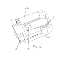
- Figur 2
- eine Schrägansicht des Temperaturschutzschalters ohne Gehäuse;
- Figur 3
- eine Ansicht zu
Figur 2 mit abgenommenem Teilkörper; - Figur 4
- eine Schnittansicht des Temperaturschutzschalters; und
- Figur 5
- ein weiteres Ausführungsbeispiel eines erfindungsgemäßen Temperaturschutzschalters.
- Der in den
Figuren 1 bis 4 dargestellte Temperaturschutzschalter hat ein erstes Anschlussblech 1, das einen Festkontakt 2 trägt, und ein zweites Anschlussblech 3, das über eine Feder 4 elektrisch leitend mit einem beweglichen Kontakt 5 verbunden ist. Die Anschlussbleche 1, 3 sind in denFiguren 1 und3 als einstückiges Stanzteil dargestellt. Nach der Montage werden die Anschlussbleche 1, 3 vereinzelt, indem ein die Anschlussbleche verbindender Steg entfernt wird. - Der Festkontakt 2 kann an dem ersten Anschlussblech 1 beispielsweise durch Schweißen oder Nieten befestigt werden. Ebenso kann die bevorzugt U-förmig gebogene Feder 4 mit dem beweglichen Kontakt 5 und mit dem zweiten Anschlussblech 3 verschweißt oder vernietet werden. Die Anschlussbleche 1, 3 sowie die Kontakte 2, 5 und die Feder 4 können zu einer Baugruppe vormontiert werden. Die Anschlussbleche 1, 3 können dabei noch als ein gemeinsames Bauteil ausgebildet sein, wie dies in
Figur 1 dargestellt ist. Wie insbesondereFigur 3 zeigt, ist die Feder 4 über einem Zwischenraum zwischen den beiden Anschlussblechen 1, 3 angeordnet. - Die beiden Anschlussbleche 1, 3 ragen aus einem Isolatorkörper heraus, der aus zwei Teilkörpern 6a, 6b zusammengesetzt ist. Die beiden Teilkörper 6a, 6b bestehen aus einem elektrisch isolierenden Material, beispielsweise aus Kunststoff. Der erste Teilkörper 6a bildet eine Aufnahme für die Anschlussbleche 1, 3, die dann von dem zweiten Teilkörper 6b verschlossen wird.
- Außen an dem Isolatorkörper, bevorzugt in einer Ausnehmung des ersten Teilkörpers 6a, ist eine Bimetallscheibe 7 angeordnet, die bei Überschreiten einer Schalttemperatur eine leitende Verbindung zwischen den beiden Anschlussblechen 1, 3 trennt. Die Bimetallscheibe 7 wirkt über einen Stößel 8 auf die Kontaktfeder 4 ein, der zwischen den beiden Anschlussblechen 1, 3 hindurch ragt. Der Stößel 8 ist in einem Kanal des ersten Teilkörpers 6a angeordnet. Wenn die Bimetallscheibe 7 bei Überschreiten ihrer Schalltemperatur umschnappt, wird der Stößel 8 von der Bimetallscheibe 7 gegen den ersten Schenkel 4a der Kontaktfeder 4 gedrückt, der den beweglichen Kontakt 5 trägt. Dabei wird der erste Schenkel 4a von dem zweiten Schenkel 4b, der an dem zweiten Anschlussblech 3 anliegt, weggebogen. Mit anderen Worten werden die beiden Schenkel 4a, 4b der Feder 4 zum Öffnen des Temperaturschutzschalters von dem Stößel 8 auseinandergebogen. Die Kontaktfeder 4 ist also eine Bügelfeder, die zum Öffnen des Temperaturschutzschalters aufgebogen wird.
- Die Bimetallscheibe 7 ist in der Ausnehmung einer Außenseite des ersten Teilkörpers 6a von einem Ring 9 gehalten. Der Ring 9 ist bevorzugt aus Metall, da so die thermische Ankopplung der Bimetallscheibe 7 an die Umgebung des Schalters verbessert ist. Der Ring 9 bedeckt den Rand der Bimetallscheibe 7 und kann beispielsweise durch Kleben oder Klemmen, beispielsweise durch Heißverprägen, an dem Teilkörper 6a des Isolatorkörpers befestigt sein. Die Bimetallscheibe 7 liegt bei dem dargestellten Ausführungsbeispiel auf einem Wulst des Isolatorkörpers auf. Auf diese Weise lässt sich die Kontaktfläche zwischen Bimetallscheibe 7 und Isolatorkörper somit auch die Wärmeankopplung der Bimetallscheibe minimieren.
- Der Isolatorkörper 6a, 6b wird nach der Montage in ein Gehäuse 10 gesteckt. Das Gehäuse 10 ist eine flache Gehäusekappe. Das Gehäuse 10 hat also eine Oberseite und eine Unterseite, die über Schmalseiten verbunden sind. An einer der Schmalseiten ist das Gehäuse 10 offen, so dass in dieses Ende des bevorzugt länglichen Gehäuses 10 der Isolatorkörper 6a, 6b eingesteckt werden kann. Bevorzugt ragen die Anschlussbleche 1, 3 mit einem Ende aus dem Gehäuse 10 heraus. Wie insbesondere
Fig. 4 zeigt, ragt der Isolatorkörper 6a, 6b aus dem Gehäuse 10 heraus. In dem aus dem Gehäuse 10 herausragenden Abschnitt des Isolatorkörpers ist ein Abschnitt der Feder 4 angeordnet, nämlich der die beiden Federschenkel 4a, 4b verbindende gebogene Abschnitt. Die Feder 4 ist also nur teilweise in dem Gehäuse 10 angeordnet. - Die Anschlussbleche 1, 3 ragen aus einer Stirnseite des Isolatorkörper 6a, 6b heraus. An der Stirnseite hat der Isolatorkörper 6a, 6b einen hervorstehenden Abschnitt, der zischen den beiden Anschlussblechen liegt. Dieser hervorstehende Abschnitt ragt aus dem Gehäuse 10 heraus und enthält den gebogenen Abschnitt der Feder 4, der die beiden Federschenkel verbindet.
- Das Gehäuse 10 kann aus ferromagnetischem Metall, beispielsweise Stahl hergestellt werden, um das Schaltwerk des Temperaturschutzschalters magnetisch abzuschirmen. Dies ist beispielsweise bei der Verwendung des Temperaturschutzschalters für Elektromotoren oder Transformatoren wichtig, da bei derartigen Anwendungen typischerweise starke Magnetfelder auftreten.
- Die Bimetallscheibe 7 ist bevorzugt eine Kreisscheibe, kann jedoch auch eine andere Form haben und beispielsweise als ein länglicher Streifen ausgebildet sein.
-
Figur 5 zeigt in einer Explosionsdarstellung ein weiteres Ausführungsbeispiel eines Temperaturschutzschalters. Dieses Ausführungsbeispiel unterscheidet sich von dem vorstehend beschriebenen Ausführungsbeispiel im Wesentlichen nur dadurch, dass eine Selbsthaltefunktion des Schalters hinzugefügt wurde. Diese Selbsthaltefunktion bewirkt, dass nach einem Öffnen des Schalters ausreichend Wärme produziert wird, um ein selbsttätiges Schließen des Schalters zu verhindern. Für die Selbsthaltefunktion ist bei dem dargestellten Ausführungsbeispiel ein Widerstand 11, bevorzugt ein keramischer Widerstand, beispielsweise ein PTC-Widerstand, vorgesehen, der die beiden Anschlussbleche 1, 3 elektrisch leitend miteinander verbindet. Der Widerstand 11 kann von einer Blattfeder 12 gegen die beiden Anschlussbleche 1, 3 gedrückt werden. - Ein elektrischer Widerstand für eine Selbsthaltefunktion kann beispielsweise auch außerhalb von dem Gehäuse, beispielsweise auf einer aus der Gehäuseöffnung herausragenden Stirnseite des Isolatorkörpers 6a, 6b angeordnet werden. Möglich ist es auch, den Isolatorkörper 6a, 6b als elektrischen Widerstand für eine Selbsthaltefunktion auszubilden. In diesem Fall ist der Isolatorkörper 6a, 6b oder zumindest einer der beiden Teilkörper 6a, 6b ein schlechter Isolator bzw. ein schlechter elektrischer Leiter, so dass bei geöffnetem Schalter durch den Isolatorkörper ein Strom fließt, der eine ausreichende Verlustwärme erzeugt, um ein Abkühlen der Bimetallscheibe 7 unter ihrer Schalttemperatur zu verhindern.
-
- 1
- erstes Anschlussblech
- 2
- Festkontakt
- 3
- zweites Anschlussblech
- 4
- Kontaktfeder
- 4a
- erste Schenkel
- 4b
- zweite Schenkel
- 5
- beweglicher Kontakt
- 6a
- erster Teilkörper
- 6b
- zweiter Teilkörper
- 7
- Bimetallscheibe
- 8
- Stößel
- 9
- Ring
- 10
- Gehäuse
- 11
- Widerstand
- 12
- Blattfeder
Claims (12)
- Temperaturschutzschalter mit
einem ersten Anschlussblech (1) mit einem Festkontakt (2),
einem zweiten Anschlussblech (3), das elektrisch leitend mit einem beweglichen Kontakt (5) verbunden ist,
einem Isolatorkörper, aus dem die beiden Anschlussbleche (1, 3) herausragen, einer Bimetallscheibe (7), die bei Überschreiten einer Schalttemperatur eine leitende Verbindung zwischen den beiden Anschlussblechen (1, 3) trennt,
einem Gehäuse (10), in das der Isolatorkörper (6a, 6b) gesteckt ist,
dadurch gekennzeichnet, dass
der bewegliche Kontakt (5) an einem ersten Schenkel (4a) einer Feder (4) befestigt ist, die mit einem zweiten Schenkel (4b) das zweite Anschlussblech (3) kontaktiert, wobei zwischen dem ersten Schenkel (4a) der Feder (4) und der Bimetallscheibe (7) ein Stößel (8) angeordnet ist, den die Bimetallscheibe (7) bei Überschreiten der Schalttemperatur gegen den ersten Schenkel (4a) drückt und so den beweglichen Kontakt (5) von dem Festkontakt (2) abhebt. - Temperaturschutzschalter nach Anspruch 1, dadurch gekennzeichnet, dass die beiden Schenkel (4a, 4b) der Feder (4) zum Öffnen des Temperaturschutzschalters von dem Stößel (8) auseinandergebogen werden.
- Temperaturschutzschalter nach einem der vorstehenden Ansprüche, dadurch gekennzeichnet, dass der zweite Schenkel (4b) der Feder (4) an dem zweiten Anschlussblech (3) anliegt.
- Temperaturschutzschalter nach einem der vorstehenden Ansprüche, dadurch gekennzeichnet, dass der Isolatorkörper aus zwei Teilkörpern (6a, 6b) zusammengesetzt ist, wobei die beiden Anschlussbleche (1, 3) zwischen den beiden Teilkörpern (6a, 6b) liegen.
- Temperaturschutzschalter nach einem der vorstehenden Ansprüche, dadurch gekennzeichnet, dass das Gehäuse (10) aus einem ferromagnetischen Material, vorzugsweise aus Stahl, ist.
- Temperaturschutzschalter nach einem der vorstehenden Ansprüche, dadurch gekennzeichnet, dass die Bimetallscheibe (7) außen an dem Isolatorkörper sitzt.
- Temperaturschutzschalter nach Anspruch 6, dadurch gekennzeichnet, dass die Bimetallscheibe (7) in einer Vertiefung an der Außenseite des Isolatorkörpers sitzt.
- Temperaturschutzschalter nach einem der vorstehenden Ansprüche, dadurch gekennzeichnet, dass der Stößel (8) bei geöffnetem Schalter zwischen den beiden Anschlussblechen (1, 3) hindurchragt.
- Thermosschalter nach einem der vorstehenden Ansprüche, dadurch gekennzeichnet, dass der Isolatorkörper einen Ring (9) trägt, der den Rand der Bimetallscheibe (7) bedeckt.
- Thermosschalter nach einem der vorstehenden Ansprüche, dadurch gekennzeichnet, dass das Gehäuse (10) eine Oberseite und eine Unterseite aufweist, die über Schmalseiten miteinander verbunden sind.
- Thermoschalter nach Anspruch 10, dadurch gekennzeichnet, dass das Gehäuse (10) an einer seiner Schmalseiten offen und mit dieser Seite auf den Isolatorkörper (6a, 6b) aufgesteckt ist.
- Thermosschalter nach einem der vorstehenden Ansprüche, dadurch gekennzeichnet, dass wenigstens einer der beiden Schenkel (4b) der Feder (4) einen seitlichen Fortsatz hat, der sich quer zur Längsrichtung des Schenkels (4b) erstreckt.
Applications Claiming Priority (1)
| Application Number | Priority Date | Filing Date | Title |
|---|---|---|---|
| DE102011016896.6A DE102011016896C5 (de) | 2011-04-13 | 2011-04-13 | Temperaturschutzschalter |
Publications (2)
| Publication Number | Publication Date |
|---|---|
| EP2511930A1 true EP2511930A1 (de) | 2012-10-17 |
| EP2511930B1 EP2511930B1 (de) | 2016-01-20 |
Family
ID=45939133
Family Applications (1)
| Application Number | Title | Priority Date | Filing Date |
|---|---|---|---|
| EP12160468.0A Active EP2511930B1 (de) | 2011-04-13 | 2012-03-21 | Temperaturschutzschalter |
Country Status (3)
| Country | Link |
|---|---|
| EP (1) | EP2511930B1 (de) |
| DE (1) | DE102011016896C5 (de) |
| PL (1) | PL2511930T3 (de) |
Cited By (7)
| Publication number | Priority date | Publication date | Assignee | Title |
|---|---|---|---|---|
| EP2843680A3 (de) * | 2013-08-07 | 2015-07-08 | Thermik Gerätebau GmbH | Temperaturabhängiger Schalter |
| CN106935440A (zh) * | 2017-05-05 | 2017-07-07 | 佛山市川东磁电股份有限公司 | 一种低阻值热敏温控器 |
| CN106960763A (zh) * | 2017-05-05 | 2017-07-18 | 佛山市川东磁电股份有限公司 | 一种稳定型低阻温控器 |
| CN106960762A (zh) * | 2017-05-05 | 2017-07-18 | 佛山市川东磁电股份有限公司 | 一种手动复位热敏温控器 |
| CN106960761A (zh) * | 2017-05-05 | 2017-07-18 | 佛山市川东磁电股份有限公司 | 一种便于微型化的温控器结构 |
| CN107230582A (zh) * | 2017-07-28 | 2017-10-03 | 宝应电器厂 | 一种双金属片式电动机热保护器及其制作工艺 |
| EP3731254A1 (de) | 2019-04-23 | 2020-10-28 | Marcel P. Hofsaess | Temperaturabhängiger schalter und verfahren zur herstellung eines temperaturabhängigen schalters |
Families Citing this family (3)
| Publication number | Priority date | Publication date | Assignee | Title |
|---|---|---|---|---|
| DE102012112207B3 (de) | 2012-12-13 | 2014-02-13 | Marcel P. HOFSAESS | Temperaturabhängiger Schalter |
| DE102013022331B4 (de) | 2013-08-07 | 2020-10-29 | Thermik Gerätebau GmbH | Temperaturabhängiger Schalter |
| DE102013108508A1 (de) | 2013-08-07 | 2015-02-12 | Thermik Gerätebau GmbH | Temperaturabhängiger Schalter |
Citations (8)
| Publication number | Priority date | Publication date | Assignee | Title |
|---|---|---|---|---|
| US3972016A (en) * | 1974-06-28 | 1976-07-27 | Therm-O-Disc Incorporated | Thermostat |
| DE3136312A1 (de) | 1981-01-29 | 1982-08-19 | Elmwood Sensors Inc., Cranston, R.I. | Thermostatschalter |
| DE19509656C2 (de) | 1995-03-17 | 1997-01-16 | Radbruch Jens Dipl Ing | Temperaturschutzschalter |
| US5936510A (en) * | 1998-05-22 | 1999-08-10 | Portage Electric Products, Inc. | Sealed case hold open thermostat |
| FR2853760A1 (fr) * | 2003-04-08 | 2004-10-15 | Etls | Dispositif thermostatique a maintien d'ouverture apres declenchement |
| EP1774555B1 (de) | 2004-07-24 | 2008-12-17 | TMC Sensortechnik GmbH | Thermobimetallschalter |
| DE102008048554B3 (de) | 2008-09-16 | 2010-02-04 | Hofsaess, Marcel P. | Temperaturabhängiger Schalter |
| EP2234138A2 (de) * | 2009-03-27 | 2010-09-29 | Inter Control Hermann Köhler Elektrik GmbH & Co. KG | Bügel/Bimetallverbindung und Verfahren zur Herstellung |
Family Cites Families (9)
| Publication number | Priority date | Publication date | Assignee | Title |
|---|---|---|---|---|
| CA1152135A (en) * | 1980-11-21 | 1983-08-16 | Karl O. Steinke | Thermal switch and method of assembly and tool used therein |
| US4669182A (en) | 1984-01-23 | 1987-06-02 | Therm-O-Disc, Incorporated | Method of gaging a snap disc condition sensor |
| US5043690A (en) * | 1990-07-12 | 1991-08-27 | Sundstrand Data Control, Inc. | Balanced snap action thermal actuator |
| US5059937A (en) * | 1990-10-23 | 1991-10-22 | Therm-O-Disc, Incorporated | Switch assembly |
| DE4414859C1 (de) * | 1994-04-28 | 1995-09-28 | Widmaier Fa Hans | Thermoschalter |
| US5703560A (en) * | 1995-09-11 | 1997-12-30 | Elmwood Sensors, Inc. | Thermostat with one-piece reset mechanism and contact assembly |
| US6597274B1 (en) * | 2000-05-30 | 2003-07-22 | Therm-O-Disc, Incorporated | Bimetal snap disc thermostat with heaters |
| JP2005005194A (ja) * | 2003-06-13 | 2005-01-06 | Hosiden Corp | サーモプロテクタ |
| DE102007014237A1 (de) * | 2007-03-16 | 2008-09-18 | Hofsaess, Marcel P. | Temperaturabhängiger Schalter und dafür vorgesehenes Schaltwerk |
-
2011
- 2011-04-13 DE DE102011016896.6A patent/DE102011016896C5/de active Active
-
2012
- 2012-03-21 PL PL12160468.0T patent/PL2511930T3/pl unknown
- 2012-03-21 EP EP12160468.0A patent/EP2511930B1/de active Active
Patent Citations (8)
| Publication number | Priority date | Publication date | Assignee | Title |
|---|---|---|---|---|
| US3972016A (en) * | 1974-06-28 | 1976-07-27 | Therm-O-Disc Incorporated | Thermostat |
| DE3136312A1 (de) | 1981-01-29 | 1982-08-19 | Elmwood Sensors Inc., Cranston, R.I. | Thermostatschalter |
| DE19509656C2 (de) | 1995-03-17 | 1997-01-16 | Radbruch Jens Dipl Ing | Temperaturschutzschalter |
| US5936510A (en) * | 1998-05-22 | 1999-08-10 | Portage Electric Products, Inc. | Sealed case hold open thermostat |
| FR2853760A1 (fr) * | 2003-04-08 | 2004-10-15 | Etls | Dispositif thermostatique a maintien d'ouverture apres declenchement |
| EP1774555B1 (de) | 2004-07-24 | 2008-12-17 | TMC Sensortechnik GmbH | Thermobimetallschalter |
| DE102008048554B3 (de) | 2008-09-16 | 2010-02-04 | Hofsaess, Marcel P. | Temperaturabhängiger Schalter |
| EP2234138A2 (de) * | 2009-03-27 | 2010-09-29 | Inter Control Hermann Köhler Elektrik GmbH & Co. KG | Bügel/Bimetallverbindung und Verfahren zur Herstellung |
Cited By (12)
| Publication number | Priority date | Publication date | Assignee | Title |
|---|---|---|---|---|
| EP2843680A3 (de) * | 2013-08-07 | 2015-07-08 | Thermik Gerätebau GmbH | Temperaturabhängiger Schalter |
| EP3229255A1 (de) * | 2013-08-07 | 2017-10-11 | Thermik Gerätebau GmbH | Temperaturabhängiger schalter |
| CN106935440A (zh) * | 2017-05-05 | 2017-07-07 | 佛山市川东磁电股份有限公司 | 一种低阻值热敏温控器 |
| CN106960763A (zh) * | 2017-05-05 | 2017-07-18 | 佛山市川东磁电股份有限公司 | 一种稳定型低阻温控器 |
| CN106960762A (zh) * | 2017-05-05 | 2017-07-18 | 佛山市川东磁电股份有限公司 | 一种手动复位热敏温控器 |
| CN106960761A (zh) * | 2017-05-05 | 2017-07-18 | 佛山市川东磁电股份有限公司 | 一种便于微型化的温控器结构 |
| CN106960761B (zh) * | 2017-05-05 | 2018-12-11 | 佛山市川东磁电股份有限公司 | 一种便于微型化的温控器结构 |
| CN106935440B (zh) * | 2017-05-05 | 2018-12-11 | 佛山市川东磁电股份有限公司 | 一种低阻值热敏温控器 |
| CN106960763B (zh) * | 2017-05-05 | 2018-12-11 | 佛山市川东磁电股份有限公司 | 一种稳定型低阻温控器 |
| CN107230582A (zh) * | 2017-07-28 | 2017-10-03 | 宝应电器厂 | 一种双金属片式电动机热保护器及其制作工艺 |
| EP3731254A1 (de) | 2019-04-23 | 2020-10-28 | Marcel P. Hofsaess | Temperaturabhängiger schalter und verfahren zur herstellung eines temperaturabhängigen schalters |
| DE102019110448A1 (de) * | 2019-04-23 | 2020-10-29 | Marcel P. HOFSAESS | Temperaturabhängiger Schalter und Verfahren zur Herstellung eines temperaturabhängigen Schalters |
Also Published As
| Publication number | Publication date |
|---|---|
| DE102011016896B3 (de) | 2012-08-23 |
| EP2511930B1 (de) | 2016-01-20 |
| DE102011016896C5 (de) | 2016-10-27 |
| PL2511930T3 (pl) | 2016-09-30 |
Similar Documents
| Publication | Publication Date | Title |
|---|---|---|
| EP2511930B1 (de) | Temperaturschutzschalter | |
| EP0887826B1 (de) | Temperaturabhängiger Schalter mit Kontaktbrücke | |
| DE19941190B4 (de) | Wärmeschutzsicherung | |
| EP2846344B1 (de) | Temperaturabhängiger Schalter | |
| DE3122899A1 (de) | Temperaturschalter | |
| DE2917482A1 (de) | Waermeschutzschalter | |
| EP0920044B1 (de) | Schalter mit einem temperaturabhängigen Schaltwerk | |
| EP1774555B1 (de) | Thermobimetallschalter | |
| EP0951040B2 (de) | Temperaturabhängiger Schalter | |
| DE19705154C2 (de) | Temperaturabhängiger Schalter mit einem Bimetall-Schaltwerk | |
| DE2917557C2 (de) | Wärmeschutzschalter | |
| DE102014108518A1 (de) | Temperaturabhängiger Schalter mit Distanzring | |
| DE102011119632B3 (de) | Temperaturabhängiges Schaltwerk | |
| EP0994497B1 (de) | Schalter mit einem Isolierstoffträger | |
| DE102011119637B4 (de) | Temperaturabhängiger Schalter mit einem temperaturabhängigen Schaltwerk sowie Verfahren zum Herstellen eines solchen Schalters | |
| DE19704563B4 (de) | Vorrichtung zum Schützen eines Gerätes | |
| EP2654057B1 (de) | Temperaturabhängiger Schalter | |
| EP0938117B1 (de) | Schalter | |
| EP2506281B1 (de) | Temperaturabhängiger Schalter mit Vorwiderstand | |
| DE69837032T2 (de) | Magnetothermische Steuervorrichtung und mit einer solchen Vorrichtung ausgerüsteter Schutzschalter | |
| EP0162940B1 (de) | Überlastsicherungsschalter | |
| DE2513494C2 (de) | Temperaturschutzschalter für Rohrheizkörper | |
| DE102023102302B3 (de) | Temperaturabhängiger Schalter | |
| DE102023102303B3 (de) | Temperaturabhängiger Schalter | |
| DE10335704A1 (de) | Elektrische Auslöseeinrichtung für ein elektrisches Schaltgerät |
Legal Events
| Date | Code | Title | Description |
|---|---|---|---|
| PUAI | Public reference made under article 153(3) epc to a published international application that has entered the european phase |
Free format text: ORIGINAL CODE: 0009012 |
|
| AK | Designated contracting states |
Kind code of ref document: A1 Designated state(s): AL AT BE BG CH CY CZ DE DK EE ES FI FR GB GR HR HU IE IS IT LI LT LU LV MC MK MT NL NO PL PT RO RS SE SI SK SM TR |
|
| AX | Request for extension of the european patent |
Extension state: BA ME |
|
| 17P | Request for examination filed |
Effective date: 20130404 |
|
| GRAP | Despatch of communication of intention to grant a patent |
Free format text: ORIGINAL CODE: EPIDOSNIGR1 |
|
| INTG | Intention to grant announced |
Effective date: 20150728 |
|
| RAP1 | Party data changed (applicant data changed or rights of an application transferred) |
Owner name: TMC SENSORTECHNIK GMBH |
|
| GRAS | Grant fee paid |
Free format text: ORIGINAL CODE: EPIDOSNIGR3 |
|
| GRAA | (expected) grant |
Free format text: ORIGINAL CODE: 0009210 |
|
| STAA | Information on the status of an ep patent application or granted ep patent |
Free format text: STATUS: THE PATENT HAS BEEN GRANTED |
|
| AK | Designated contracting states |
Kind code of ref document: B1 Designated state(s): AL AT BE BG CH CY CZ DE DK EE ES FI FR GB GR HR HU IE IS IT LI LT LU LV MC MK MT NL NO PL PT RO RS SE SI SK SM TR |
|
| REG | Reference to a national code |
Ref country code: GB Ref legal event code: FG4D Free format text: NOT ENGLISH |
|
| REG | Reference to a national code |
Ref country code: CH Ref legal event code: EP |
|
| REG | Reference to a national code |
Ref country code: IE Ref legal event code: FG4D Free format text: LANGUAGE OF EP DOCUMENT: GERMAN |
|
| REG | Reference to a national code |
Ref country code: AT Ref legal event code: REF Ref document number: 772067 Country of ref document: AT Kind code of ref document: T Effective date: 20160215 |
|
| REG | Reference to a national code |
Ref country code: DE Ref legal event code: R096 Ref document number: 502012005758 Country of ref document: DE |
|
| REG | Reference to a national code |
Ref country code: LT Ref legal event code: MG4D Ref country code: NL Ref legal event code: MP Effective date: 20160120 |
|
| PG25 | Lapsed in a contracting state [announced via postgrant information from national office to epo] |
Ref country code: NL Free format text: LAPSE BECAUSE OF FAILURE TO SUBMIT A TRANSLATION OF THE DESCRIPTION OR TO PAY THE FEE WITHIN THE PRESCRIBED TIME-LIMIT Effective date: 20160120 |
|
| PG25 | Lapsed in a contracting state [announced via postgrant information from national office to epo] |
Ref country code: ES Free format text: LAPSE BECAUSE OF FAILURE TO SUBMIT A TRANSLATION OF THE DESCRIPTION OR TO PAY THE FEE WITHIN THE PRESCRIBED TIME-LIMIT Effective date: 20160120 Ref country code: GR Free format text: LAPSE BECAUSE OF FAILURE TO SUBMIT A TRANSLATION OF THE DESCRIPTION OR TO PAY THE FEE WITHIN THE PRESCRIBED TIME-LIMIT Effective date: 20160421 Ref country code: NO Free format text: LAPSE BECAUSE OF FAILURE TO SUBMIT A TRANSLATION OF THE DESCRIPTION OR TO PAY THE FEE WITHIN THE PRESCRIBED TIME-LIMIT Effective date: 20160420 Ref country code: FI Free format text: LAPSE BECAUSE OF FAILURE TO SUBMIT A TRANSLATION OF THE DESCRIPTION OR TO PAY THE FEE WITHIN THE PRESCRIBED TIME-LIMIT Effective date: 20160120 Ref country code: HR Free format text: LAPSE BECAUSE OF FAILURE TO SUBMIT A TRANSLATION OF THE DESCRIPTION OR TO PAY THE FEE WITHIN THE PRESCRIBED TIME-LIMIT Effective date: 20160120 |
|
| PG25 | Lapsed in a contracting state [announced via postgrant information from national office to epo] |
Ref country code: PT Free format text: LAPSE BECAUSE OF FAILURE TO SUBMIT A TRANSLATION OF THE DESCRIPTION OR TO PAY THE FEE WITHIN THE PRESCRIBED TIME-LIMIT Effective date: 20160520 Ref country code: LT Free format text: LAPSE BECAUSE OF FAILURE TO SUBMIT A TRANSLATION OF THE DESCRIPTION OR TO PAY THE FEE WITHIN THE PRESCRIBED TIME-LIMIT Effective date: 20160120 Ref country code: RS Free format text: LAPSE BECAUSE OF FAILURE TO SUBMIT A TRANSLATION OF THE DESCRIPTION OR TO PAY THE FEE WITHIN THE PRESCRIBED TIME-LIMIT Effective date: 20160120 Ref country code: BE Free format text: LAPSE BECAUSE OF NON-PAYMENT OF DUE FEES Effective date: 20160331 Ref country code: LV Free format text: LAPSE BECAUSE OF FAILURE TO SUBMIT A TRANSLATION OF THE DESCRIPTION OR TO PAY THE FEE WITHIN THE PRESCRIBED TIME-LIMIT Effective date: 20160120 Ref country code: IS Free format text: LAPSE BECAUSE OF FAILURE TO SUBMIT A TRANSLATION OF THE DESCRIPTION OR TO PAY THE FEE WITHIN THE PRESCRIBED TIME-LIMIT Effective date: 20160520 Ref country code: SE Free format text: LAPSE BECAUSE OF FAILURE TO SUBMIT A TRANSLATION OF THE DESCRIPTION OR TO PAY THE FEE WITHIN THE PRESCRIBED TIME-LIMIT Effective date: 20160120 |
|
| REG | Reference to a national code |
Ref country code: DE Ref legal event code: R026 Ref document number: 502012005758 Country of ref document: DE |
|
| PLBI | Opposition filed |
Free format text: ORIGINAL CODE: 0009260 |
|
| PG25 | Lapsed in a contracting state [announced via postgrant information from national office to epo] |
Ref country code: EE Free format text: LAPSE BECAUSE OF FAILURE TO SUBMIT A TRANSLATION OF THE DESCRIPTION OR TO PAY THE FEE WITHIN THE PRESCRIBED TIME-LIMIT Effective date: 20160120 Ref country code: MC Free format text: LAPSE BECAUSE OF FAILURE TO SUBMIT A TRANSLATION OF THE DESCRIPTION OR TO PAY THE FEE WITHIN THE PRESCRIBED TIME-LIMIT Effective date: 20160120 Ref country code: LU Free format text: LAPSE BECAUSE OF FAILURE TO SUBMIT A TRANSLATION OF THE DESCRIPTION OR TO PAY THE FEE WITHIN THE PRESCRIBED TIME-LIMIT Effective date: 20160321 Ref country code: DK Free format text: LAPSE BECAUSE OF FAILURE TO SUBMIT A TRANSLATION OF THE DESCRIPTION OR TO PAY THE FEE WITHIN THE PRESCRIBED TIME-LIMIT Effective date: 20160120 |
|
| REG | Reference to a national code |
Ref country code: CH Ref legal event code: PL |
|
| 26 | Opposition filed |
Opponent name: THERMIK GERAETEBAU GMBH Effective date: 20161014 |
|
| PLAX | Notice of opposition and request to file observation + time limit sent |
Free format text: ORIGINAL CODE: EPIDOSNOBS2 |
|
| PG25 | Lapsed in a contracting state [announced via postgrant information from national office to epo] |
Ref country code: SK Free format text: LAPSE BECAUSE OF FAILURE TO SUBMIT A TRANSLATION OF THE DESCRIPTION OR TO PAY THE FEE WITHIN THE PRESCRIBED TIME-LIMIT Effective date: 20160120 Ref country code: SM Free format text: LAPSE BECAUSE OF FAILURE TO SUBMIT A TRANSLATION OF THE DESCRIPTION OR TO PAY THE FEE WITHIN THE PRESCRIBED TIME-LIMIT Effective date: 20160120 Ref country code: CZ Free format text: LAPSE BECAUSE OF FAILURE TO SUBMIT A TRANSLATION OF THE DESCRIPTION OR TO PAY THE FEE WITHIN THE PRESCRIBED TIME-LIMIT Effective date: 20160120 Ref country code: RO Free format text: LAPSE BECAUSE OF FAILURE TO SUBMIT A TRANSLATION OF THE DESCRIPTION OR TO PAY THE FEE WITHIN THE PRESCRIBED TIME-LIMIT Effective date: 20160120 |
|
| GBPC | Gb: european patent ceased through non-payment of renewal fee |
Effective date: 20160420 |
|
| REG | Reference to a national code |
Ref country code: IE Ref legal event code: MM4A |
|
| REG | Reference to a national code |
Ref country code: FR Ref legal event code: ST Effective date: 20161130 |
|
| PG25 | Lapsed in a contracting state [announced via postgrant information from national office to epo] |
Ref country code: IE Free format text: LAPSE BECAUSE OF NON-PAYMENT OF DUE FEES Effective date: 20160321 Ref country code: CH Free format text: LAPSE BECAUSE OF NON-PAYMENT OF DUE FEES Effective date: 20160331 Ref country code: GB Free format text: LAPSE BECAUSE OF NON-PAYMENT OF DUE FEES Effective date: 20160420 Ref country code: FR Free format text: LAPSE BECAUSE OF NON-PAYMENT OF DUE FEES Effective date: 20160331 Ref country code: LI Free format text: LAPSE BECAUSE OF NON-PAYMENT OF DUE FEES Effective date: 20160331 |
|
| PG25 | Lapsed in a contracting state [announced via postgrant information from national office to epo] |
Ref country code: SI Free format text: LAPSE BECAUSE OF FAILURE TO SUBMIT A TRANSLATION OF THE DESCRIPTION OR TO PAY THE FEE WITHIN THE PRESCRIBED TIME-LIMIT Effective date: 20160120 Ref country code: BG Free format text: LAPSE BECAUSE OF FAILURE TO SUBMIT A TRANSLATION OF THE DESCRIPTION OR TO PAY THE FEE WITHIN THE PRESCRIBED TIME-LIMIT Effective date: 20160420 |
|
| PLBB | Reply of patent proprietor to notice(s) of opposition received |
Free format text: ORIGINAL CODE: EPIDOSNOBS3 |
|
| PGFP | Annual fee paid to national office [announced via postgrant information from national office to epo] |
Ref country code: AT Payment date: 20170322 Year of fee payment: 6 |
|
| PG25 | Lapsed in a contracting state [announced via postgrant information from national office to epo] |
Ref country code: MT Free format text: LAPSE BECAUSE OF FAILURE TO SUBMIT A TRANSLATION OF THE DESCRIPTION OR TO PAY THE FEE WITHIN THE PRESCRIBED TIME-LIMIT Effective date: 20160120 |
|
| PLCK | Communication despatched that opposition was rejected |
Free format text: ORIGINAL CODE: EPIDOSNREJ1 |
|
| STAA | Information on the status of an ep patent application or granted ep patent |
Free format text: STATUS: THE PATENT HAS BEEN GRANTED |
|
| PG25 | Lapsed in a contracting state [announced via postgrant information from national office to epo] |
Ref country code: CY Free format text: LAPSE BECAUSE OF FAILURE TO SUBMIT A TRANSLATION OF THE DESCRIPTION OR TO PAY THE FEE WITHIN THE PRESCRIBED TIME-LIMIT Effective date: 20160120 Ref country code: HU Free format text: LAPSE BECAUSE OF FAILURE TO SUBMIT A TRANSLATION OF THE DESCRIPTION OR TO PAY THE FEE WITHIN THE PRESCRIBED TIME-LIMIT; INVALID AB INITIO Effective date: 20120321 |
|
| APAH | Appeal reference modified |
Free format text: ORIGINAL CODE: EPIDOSCREFNO |
|
| APBM | Appeal reference recorded |
Free format text: ORIGINAL CODE: EPIDOSNREFNO |
|
| APBP | Date of receipt of notice of appeal recorded |
Free format text: ORIGINAL CODE: EPIDOSNNOA2O |
|
| PG25 | Lapsed in a contracting state [announced via postgrant information from national office to epo] |
Ref country code: TR Free format text: LAPSE BECAUSE OF FAILURE TO SUBMIT A TRANSLATION OF THE DESCRIPTION OR TO PAY THE FEE WITHIN THE PRESCRIBED TIME-LIMIT Effective date: 20160120 Ref country code: MK Free format text: LAPSE BECAUSE OF FAILURE TO SUBMIT A TRANSLATION OF THE DESCRIPTION OR TO PAY THE FEE WITHIN THE PRESCRIBED TIME-LIMIT Effective date: 20160120 |
|
| APBQ | Date of receipt of statement of grounds of appeal recorded |
Free format text: ORIGINAL CODE: EPIDOSNNOA3O |
|
| PG25 | Lapsed in a contracting state [announced via postgrant information from national office to epo] |
Ref country code: AL Free format text: LAPSE BECAUSE OF FAILURE TO SUBMIT A TRANSLATION OF THE DESCRIPTION OR TO PAY THE FEE WITHIN THE PRESCRIBED TIME-LIMIT Effective date: 20160120 |
|
| REG | Reference to a national code |
Ref country code: AT Ref legal event code: MM01 Ref document number: 772067 Country of ref document: AT Kind code of ref document: T Effective date: 20180321 |
|
| PG25 | Lapsed in a contracting state [announced via postgrant information from national office to epo] |
Ref country code: AT Free format text: LAPSE BECAUSE OF NON-PAYMENT OF DUE FEES Effective date: 20180321 |
|
| APBY | Invitation to file observations in appeal sent |
Free format text: ORIGINAL CODE: EPIDOSNOBA2O |
|
| APBU | Appeal procedure closed |
Free format text: ORIGINAL CODE: EPIDOSNNOA9O |
|
| PGFP | Annual fee paid to national office [announced via postgrant information from national office to epo] |
Ref country code: PL Payment date: 20230303 Year of fee payment: 12 |
|
| PGFP | Annual fee paid to national office [announced via postgrant information from national office to epo] |
Ref country code: IT Payment date: 20230331 Year of fee payment: 12 |
|
| APBM | Appeal reference recorded |
Free format text: ORIGINAL CODE: EPIDOSNREFNO |
|
| APBP | Date of receipt of notice of appeal recorded |
Free format text: ORIGINAL CODE: EPIDOSNNOA2O |
|
| APAH | Appeal reference modified |
Free format text: ORIGINAL CODE: EPIDOSCREFNO |
|
| APBQ | Date of receipt of statement of grounds of appeal recorded |
Free format text: ORIGINAL CODE: EPIDOSNNOA3O |
|
| PGFP | Annual fee paid to national office [announced via postgrant information from national office to epo] |
Ref country code: DE Payment date: 20240125 Year of fee payment: 13 |