EP2511229A1 - Composant micromécanique doté de flancs renforcés - Google Patents
Composant micromécanique doté de flancs renforcés Download PDFInfo
- Publication number
- EP2511229A1 EP2511229A1 EP11003088A EP11003088A EP2511229A1 EP 2511229 A1 EP2511229 A1 EP 2511229A1 EP 11003088 A EP11003088 A EP 11003088A EP 11003088 A EP11003088 A EP 11003088A EP 2511229 A1 EP2511229 A1 EP 2511229A1
- Authority
- EP
- European Patent Office
- Prior art keywords
- diamond
- coating
- micromechanical component
- layer thickness
- component
- Prior art date
- Legal status (The legal status is an assumption and is not a legal conclusion. Google has not performed a legal analysis and makes no representation as to the accuracy of the status listed.)
- Granted
Links
- 229910003460 diamond Inorganic materials 0.000 claims abstract description 77
- 239000010432 diamond Substances 0.000 claims abstract description 77
- 238000000576 coating method Methods 0.000 claims abstract description 56
- 239000011248 coating agent Substances 0.000 claims abstract description 53
- 239000000758 substrate Substances 0.000 claims abstract description 27
- 239000012876 carrier material Substances 0.000 claims abstract description 21
- 229910052710 silicon Inorganic materials 0.000 claims abstract description 18
- 239000010703 silicon Substances 0.000 claims abstract description 18
- OKTJSMMVPCPJKN-UHFFFAOYSA-N Carbon Chemical compound [C] OKTJSMMVPCPJKN-UHFFFAOYSA-N 0.000 claims abstract description 13
- 238000000034 method Methods 0.000 claims abstract description 13
- 229910052799 carbon Inorganic materials 0.000 claims abstract description 12
- 230000006911 nucleation Effects 0.000 claims abstract description 3
- 238000010899 nucleation Methods 0.000 claims abstract description 3
- XUIMIQQOPSSXEZ-UHFFFAOYSA-N Silicon Chemical compound [Si] XUIMIQQOPSSXEZ-UHFFFAOYSA-N 0.000 claims description 17
- 239000000463 material Substances 0.000 claims description 14
- 229910052721 tungsten Inorganic materials 0.000 claims description 7
- 238000005530 etching Methods 0.000 claims description 6
- 229910052759 nickel Inorganic materials 0.000 claims description 6
- 230000002787 reinforcement Effects 0.000 claims description 6
- 229910052751 metal Inorganic materials 0.000 claims description 5
- 239000002184 metal Substances 0.000 claims description 5
- 229910052750 molybdenum Inorganic materials 0.000 claims description 5
- 229910052715 tantalum Inorganic materials 0.000 claims description 5
- 239000007769 metal material Substances 0.000 claims description 4
- 229910052804 chromium Inorganic materials 0.000 claims description 3
- 229910052802 copper Inorganic materials 0.000 claims description 3
- 229910052732 germanium Inorganic materials 0.000 claims description 3
- GNPVGFCGXDBREM-UHFFFAOYSA-N germanium atom Chemical compound [Ge] GNPVGFCGXDBREM-UHFFFAOYSA-N 0.000 claims description 3
- 229910052742 iron Inorganic materials 0.000 claims description 3
- 229910052748 manganese Inorganic materials 0.000 claims description 3
- 150000001247 metal acetylides Chemical class 0.000 claims description 3
- 229910052758 niobium Inorganic materials 0.000 claims description 3
- 229910052697 platinum Inorganic materials 0.000 claims description 3
- 230000008569 process Effects 0.000 claims description 3
- 229910052720 vanadium Inorganic materials 0.000 claims description 3
- 239000000956 alloy Substances 0.000 claims description 2
- 229910045601 alloy Inorganic materials 0.000 claims description 2
- 150000002739 metals Chemical class 0.000 claims description 2
- 238000000992 sputter etching Methods 0.000 claims description 2
- 238000009832 plasma treatment Methods 0.000 claims 1
- 238000004381 surface treatment Methods 0.000 claims 1
- UONOETXJSWQNOL-UHFFFAOYSA-N tungsten carbide Chemical compound [W+]#[C-] UONOETXJSWQNOL-UHFFFAOYSA-N 0.000 claims 1
- 238000004519 manufacturing process Methods 0.000 abstract description 5
- 230000015572 biosynthetic process Effects 0.000 abstract description 4
- 238000005229 chemical vapour deposition Methods 0.000 abstract description 4
- 239000007858 starting material Substances 0.000 abstract 1
- 239000002245 particle Substances 0.000 description 7
- -1 Siliziumnitrid Chemical compound 0.000 description 6
- 238000005452 bending Methods 0.000 description 6
- PXHVJJICTQNCMI-UHFFFAOYSA-N nickel Substances [Ni] PXHVJJICTQNCMI-UHFFFAOYSA-N 0.000 description 6
- 235000019592 roughness Nutrition 0.000 description 6
- 230000008901 benefit Effects 0.000 description 5
- 230000003746 surface roughness Effects 0.000 description 5
- 229910052719 titanium Inorganic materials 0.000 description 5
- 239000010936 titanium Substances 0.000 description 5
- 230000007423 decrease Effects 0.000 description 4
- 230000000694 effects Effects 0.000 description 4
- 238000005259 measurement Methods 0.000 description 4
- HBMJWWWQQXIZIP-UHFFFAOYSA-N silicon carbide Chemical compound [Si+]#[C-] HBMJWWWQQXIZIP-UHFFFAOYSA-N 0.000 description 4
- 238000012360 testing method Methods 0.000 description 4
- 229910010293 ceramic material Inorganic materials 0.000 description 3
- 239000013078 crystal Substances 0.000 description 3
- 230000003247 decreasing effect Effects 0.000 description 3
- 238000000708 deep reactive-ion etching Methods 0.000 description 3
- 230000032798 delamination Effects 0.000 description 3
- 238000013461 design Methods 0.000 description 3
- 210000002381 plasma Anatomy 0.000 description 3
- 238000005498 polishing Methods 0.000 description 3
- OANVFVBYPNXRLD-UHFFFAOYSA-M propyromazine bromide Chemical compound [Br-].C12=CC=CC=C2SC2=CC=CC=C2N1C(=O)C(C)[N+]1(C)CCCC1 OANVFVBYPNXRLD-UHFFFAOYSA-M 0.000 description 3
- 239000003870 refractory metal Substances 0.000 description 3
- 229910010271 silicon carbide Inorganic materials 0.000 description 3
- IJGRMHOSHXDMSA-UHFFFAOYSA-N Atomic nitrogen Chemical compound N#N IJGRMHOSHXDMSA-UHFFFAOYSA-N 0.000 description 2
- PZNSFCLAULLKQX-UHFFFAOYSA-N Boron nitride Chemical compound N#B PZNSFCLAULLKQX-UHFFFAOYSA-N 0.000 description 2
- VYPSYNLAJGMNEJ-UHFFFAOYSA-N Silicium dioxide Chemical compound O=[Si]=O VYPSYNLAJGMNEJ-UHFFFAOYSA-N 0.000 description 2
- 229910000831 Steel Inorganic materials 0.000 description 2
- 229910010037 TiAlN Inorganic materials 0.000 description 2
- QVGXLLKOCUKJST-UHFFFAOYSA-N atomic oxygen Chemical compound [O] QVGXLLKOCUKJST-UHFFFAOYSA-N 0.000 description 2
- 229910017052 cobalt Inorganic materials 0.000 description 2
- 239000010941 cobalt Substances 0.000 description 2
- GUTLYIVDDKVIGB-UHFFFAOYSA-N cobalt atom Chemical compound [Co] GUTLYIVDDKVIGB-UHFFFAOYSA-N 0.000 description 2
- 239000002131 composite material Substances 0.000 description 2
- 230000001419 dependent effect Effects 0.000 description 2
- 238000011156 evaluation Methods 0.000 description 2
- 230000005021 gait Effects 0.000 description 2
- 238000000227 grinding Methods 0.000 description 2
- 239000011159 matrix material Substances 0.000 description 2
- 229910052760 oxygen Inorganic materials 0.000 description 2
- 239000001301 oxygen Substances 0.000 description 2
- 238000001020 plasma etching Methods 0.000 description 2
- 239000010959 steel Substances 0.000 description 2
- 235000019587 texture Nutrition 0.000 description 2
- 239000010937 tungsten Substances 0.000 description 2
- 229910018072 Al 2 O 3 Inorganic materials 0.000 description 1
- QYEXBYZXHDUPRC-UHFFFAOYSA-N B#[Ti]#B Chemical compound B#[Ti]#B QYEXBYZXHDUPRC-UHFFFAOYSA-N 0.000 description 1
- 229910052582 BN Inorganic materials 0.000 description 1
- ZOXJGFHDIHLPTG-UHFFFAOYSA-N Boron Chemical compound [B] ZOXJGFHDIHLPTG-UHFFFAOYSA-N 0.000 description 1
- CWYNVVGOOAEACU-UHFFFAOYSA-N Fe2+ Chemical compound [Fe+2] CWYNVVGOOAEACU-UHFFFAOYSA-N 0.000 description 1
- YCKRFDGAMUMZLT-UHFFFAOYSA-N Fluorine atom Chemical compound [F] YCKRFDGAMUMZLT-UHFFFAOYSA-N 0.000 description 1
- 229910052581 Si3N4 Inorganic materials 0.000 description 1
- 229910033181 TiB2 Inorganic materials 0.000 description 1
- RTAQQCXQSZGOHL-UHFFFAOYSA-N Titanium Chemical compound [Ti] RTAQQCXQSZGOHL-UHFFFAOYSA-N 0.000 description 1
- 239000003082 abrasive agent Substances 0.000 description 1
- 230000006978 adaptation Effects 0.000 description 1
- 239000002318 adhesion promoter Substances 0.000 description 1
- 239000000853 adhesive Substances 0.000 description 1
- 230000001070 adhesive effect Effects 0.000 description 1
- 229910052796 boron Inorganic materials 0.000 description 1
- 239000000919 ceramic Substances 0.000 description 1
- 230000008859 change Effects 0.000 description 1
- 238000003486 chemical etching Methods 0.000 description 1
- 238000005520 cutting process Methods 0.000 description 1
- 238000000151 deposition Methods 0.000 description 1
- 230000008021 deposition Effects 0.000 description 1
- 238000011161 development Methods 0.000 description 1
- 230000018109 developmental process Effects 0.000 description 1
- 238000009826 distribution Methods 0.000 description 1
- 230000005489 elastic deformation Effects 0.000 description 1
- 238000007786 electrostatic charging Methods 0.000 description 1
- 239000011737 fluorine Substances 0.000 description 1
- 229910052731 fluorine Inorganic materials 0.000 description 1
- 239000002241 glass-ceramic Substances 0.000 description 1
- 229910002804 graphite Inorganic materials 0.000 description 1
- 239000010439 graphite Substances 0.000 description 1
- 238000011065 in-situ storage Methods 0.000 description 1
- 239000012212 insulator Substances 0.000 description 1
- 238000010884 ion-beam technique Methods 0.000 description 1
- 150000002500 ions Chemical class 0.000 description 1
- 230000000873 masking effect Effects 0.000 description 1
- 229910003465 moissanite Inorganic materials 0.000 description 1
- 229910052757 nitrogen Inorganic materials 0.000 description 1
- 230000035515 penetration Effects 0.000 description 1
- 238000000206 photolithography Methods 0.000 description 1
- 230000000704 physical effect Effects 0.000 description 1
- 238000012545 processing Methods 0.000 description 1
- 238000011321 prophylaxis Methods 0.000 description 1
- 230000009467 reduction Effects 0.000 description 1
- 229910052594 sapphire Inorganic materials 0.000 description 1
- 239000010980 sapphire Substances 0.000 description 1
- 150000003376 silicon Chemical class 0.000 description 1
- 235000012239 silicon dioxide Nutrition 0.000 description 1
- 239000000377 silicon dioxide Substances 0.000 description 1
- HQVNEWCFYHHQES-UHFFFAOYSA-N silicon nitride Chemical compound N12[Si]34N5[Si]62N3[Si]51N64 HQVNEWCFYHHQES-UHFFFAOYSA-N 0.000 description 1
- 229910052814 silicon oxide Inorganic materials 0.000 description 1
- 238000010972 statistical evaluation Methods 0.000 description 1
- 239000000725 suspension Substances 0.000 description 1
- WFKWXMTUELFFGS-UHFFFAOYSA-N tungsten Chemical compound [W] WFKWXMTUELFFGS-UHFFFAOYSA-N 0.000 description 1
- 238000002604 ultrasonography Methods 0.000 description 1
- 238000007740 vapor deposition Methods 0.000 description 1
Images


Classifications
-
- B—PERFORMING OPERATIONS; TRANSPORTING
- B81—MICROSTRUCTURAL TECHNOLOGY
- B81B—MICROSTRUCTURAL DEVICES OR SYSTEMS, e.g. MICROMECHANICAL DEVICES
- B81B3/00—Devices comprising flexible or deformable elements, e.g. comprising elastic tongues or membranes
- B81B3/0064—Constitution or structural means for improving or controlling the physical properties of a device
- B81B3/0067—Mechanical properties
- B81B3/0075—For improving wear resistance
-
- B—PERFORMING OPERATIONS; TRANSPORTING
- B81—MICROSTRUCTURAL TECHNOLOGY
- B81C—PROCESSES OR APPARATUS SPECIALLY ADAPTED FOR THE MANUFACTURE OR TREATMENT OF MICROSTRUCTURAL DEVICES OR SYSTEMS
- B81C1/00—Manufacture or treatment of devices or systems in or on a substrate
- B81C1/00642—Manufacture or treatment of devices or systems in or on a substrate for improving the physical properties of a device
- B81C1/0065—Mechanical properties
- B81C1/00674—Treatments for improving wear resistance
-
- G—PHYSICS
- G04—HOROLOGY
- G04B—MECHANICALLY-DRIVEN CLOCKS OR WATCHES; MECHANICAL PARTS OF CLOCKS OR WATCHES IN GENERAL; TIME PIECES USING THE POSITION OF THE SUN, MOON OR STARS
- G04B1/00—Driving mechanisms
- G04B1/10—Driving mechanisms with mainspring
- G04B1/14—Mainsprings; Bridles therefor
- G04B1/145—Composition and manufacture of the springs
-
- G—PHYSICS
- G04—HOROLOGY
- G04B—MECHANICALLY-DRIVEN CLOCKS OR WATCHES; MECHANICAL PARTS OF CLOCKS OR WATCHES IN GENERAL; TIME PIECES USING THE POSITION OF THE SUN, MOON OR STARS
- G04B13/00—Gearwork
- G04B13/02—Wheels; Pinions; Spindles; Pivots
-
- G—PHYSICS
- G04—HOROLOGY
- G04B—MECHANICALLY-DRIVEN CLOCKS OR WATCHES; MECHANICAL PARTS OF CLOCKS OR WATCHES IN GENERAL; TIME PIECES USING THE POSITION OF THE SUN, MOON OR STARS
- G04B15/00—Escapements
- G04B15/14—Component parts or constructional details, e.g. construction of the lever or the escape wheel
-
- G—PHYSICS
- G04—HOROLOGY
- G04B—MECHANICALLY-DRIVEN CLOCKS OR WATCHES; MECHANICAL PARTS OF CLOCKS OR WATCHES IN GENERAL; TIME PIECES USING THE POSITION OF THE SUN, MOON OR STARS
- G04B17/00—Mechanisms for stabilising frequency
- G04B17/04—Oscillators acting by spring tension
- G04B17/06—Oscillators with hairsprings, e.g. balance
- G04B17/063—Balance construction
-
- G—PHYSICS
- G04—HOROLOGY
- G04B—MECHANICALLY-DRIVEN CLOCKS OR WATCHES; MECHANICAL PARTS OF CLOCKS OR WATCHES IN GENERAL; TIME PIECES USING THE POSITION OF THE SUN, MOON OR STARS
- G04B17/00—Mechanisms for stabilising frequency
- G04B17/04—Oscillators acting by spring tension
- G04B17/06—Oscillators with hairsprings, e.g. balance
- G04B17/066—Manufacture of the spiral spring
-
- G—PHYSICS
- G04—HOROLOGY
- G04B—MECHANICALLY-DRIVEN CLOCKS OR WATCHES; MECHANICAL PARTS OF CLOCKS OR WATCHES IN GENERAL; TIME PIECES USING THE POSITION OF THE SUN, MOON OR STARS
- G04B31/00—Bearings; Point suspensions or counter-point suspensions; Pivot bearings; Single parts therefor
- G04B31/004—Bearings; Point suspensions or counter-point suspensions; Pivot bearings; Single parts therefor characterised by the material used
-
- Y—GENERAL TAGGING OF NEW TECHNOLOGICAL DEVELOPMENTS; GENERAL TAGGING OF CROSS-SECTIONAL TECHNOLOGIES SPANNING OVER SEVERAL SECTIONS OF THE IPC; TECHNICAL SUBJECTS COVERED BY FORMER USPC CROSS-REFERENCE ART COLLECTIONS [XRACs] AND DIGESTS
- Y10—TECHNICAL SUBJECTS COVERED BY FORMER USPC
- Y10T—TECHNICAL SUBJECTS COVERED BY FORMER US CLASSIFICATION
- Y10T428/00—Stock material or miscellaneous articles
- Y10T428/23—Sheet including cover or casing
- Y10T428/239—Complete cover or casing
-
- Y—GENERAL TAGGING OF NEW TECHNOLOGICAL DEVELOPMENTS; GENERAL TAGGING OF CROSS-SECTIONAL TECHNOLOGIES SPANNING OVER SEVERAL SECTIONS OF THE IPC; TECHNICAL SUBJECTS COVERED BY FORMER USPC CROSS-REFERENCE ART COLLECTIONS [XRACs] AND DIGESTS
- Y10—TECHNICAL SUBJECTS COVERED BY FORMER USPC
- Y10T—TECHNICAL SUBJECTS COVERED BY FORMER US CLASSIFICATION
- Y10T428/00—Stock material or miscellaneous articles
- Y10T428/24—Structurally defined web or sheet [e.g., overall dimension, etc.]
- Y10T428/24777—Edge feature
- Y10T428/24793—Comprising discontinuous or differential impregnation or bond
Definitions
- the invention relates to a micromechanical component, which consists of a carrier material having a top and a bottom and at least two side surfaces and a coating surrounding the substrate, wherein the coating of diamond and / or diamond-like carbon is formed.
- the micromechanical component according to the invention is characterized in that the coating of diamond and / or diamond-like carbon at least on at least one side surface of the micromechanical component has a smaller layer thickness than on the top and / or bottom of the component, so that a reinforced area arises.
- Composites of a carrier material and diamond are known.
- the German Offenlegungsschrift describes DE 10 2004 052 068 A1 on Cutting tool and a method for its production, in which a coating of diamond is applied to a carrier material, which is metallic, for example.
- micromechanical components are known, which consist of a carrier material, which are coated over the entire surface with a layer of diamond or DLC. That's how it describes DE 10 2008 041 778 A1 a tension spring for a barrel of a clockwork, said tension spring consists of a support material, such as silicon, and that this support material is coated over its entire surface with a layer of diamond or DLC.
- a diamond layer is applied to the carrier material, which is rectangular in cross-section according to the above-mentioned publication, a diamond layer which surrounds the carrier material over its entire surface and thereby has the same thickness everywhere.
- a disadvantage of these previously known micromechanical components is that the component is not optimally adapted to its application or load case, since, for example, in the case of the tension spring, the forces acting on the tension spring are not constant over the entire length of the spring, so that As a result, no optimal gait behavior can be achieved yet.
- other components which are provided with a diamond layer and in Contact with other components, since the forces act only selectively, eg at the contact points. This applies, among other things, for anchor and escape wheel but also for all gear train and bearing components.
- micromechanical components which are designed to suit their purpose with regard to the required physical and mechanical properties, ie. be optimally adapted to the specific mechanical load case.
- the micromechanical component should be inexpensive to produce.
- the component should moreover be light (low mass or low moment of inertia) and an arbitrarily complex shaped geometry can be realized.
- a micromechanical component with a top and bottom as well as a carrier material having at least two side surfaces with a coating of diamond and / or diamond-like carbon (DLC) surrounding the surfaces of the carrier material, so that a three-dimensional coating is present.
- DLC diamond-like carbon
- the diamond layer which is used according to the invention in the component is preferably a microcrystalline and / or nanocrystalline diamond layer.
- Advantageous average particle sizes are in the range between 5 and 100 nm, very particularly preferably in the range between 1 and 10 nm.
- nanocrystalline diamond is understood to mean a diamond layer, the crystalline domains having an average particle size d 50 of ⁇ 100 nm. This definition implies that for at least 50% of the crystallites, each dimension of a single crystallite is ⁇ 500 nm.
- the nanocrystalline diamond layer thus distinguishes itself, in contrast to polycrystalline diamond layers, by an extremely high homogeneity of the crystallites.
- the gradient of the mean grain size of the nanocrystalline diamond measured in the direction of the thickness of the nanocrystalline diamond layer is ⁇ 300%, preferably ⁇ 100%, particularly preferably ⁇ 50%.
- This embodiment provides that the mean grain size diameter of the nanocrystalline domains of the diamond layer is distributed relatively evenly to particularly evenly through the entire layer thickness, ie the grain sizes are approximately the same on one side of the diamond layer as on the other side of the diamond layer; Of course, it is particularly advantageous almost or completely complete homogeneity of the nanocrystalline domains of the diamond layer.
- the gradient is determined by determining the average grain size diameter d 50 on one side of the diamond layer and set in relation to the average grain size diameter on the opposite side of the diamond layer. In this case, for example, the mean particle size distribution can be used on the surface of the respective diamond layer.
- a further embodiment provides that the proportion of sp and sp 2 bonds of the fine crystalline diamond layer is between 0.5 and 10%, preferably between 2 and 9%, particularly preferably between 3 and 8%.
- a further preferred embodiment of the present invention provides that an adhesion promoter layer, preferably of silicon carbide, tungsten, titanium or silicon, is optionally applied or formed in-situ between the substrate and the finely crystalline diamond layer. This embodiment ensures a good hold of the diamond layer on the substrate.
- an adhesion promoter layer preferably of silicon carbide, tungsten, titanium or silicon
- the crystallites of the finely crystalline diamond layer are preferably grown in the ⁇ 100>, ⁇ 110> and / or ⁇ 111> direction, ie a texture is present. This can result from the manufacturing process, in which the growth rate of certain crystal directions can be specifically favored. This anisotropic texture of the crystallites also positively affects the mechanical properties.
- the individual grains are very small in the case of nanocrystalline diamond layers as explained above.
- a grain boundary which generally represents a weak point of the material, thus also has very small dimensions, in particular when considering the ratio of the grain boundary extent to the layer thickness of the diamond layer.
- the grain boundary in the nanocrystalline diamond no longer represents a microscopic predetermined breaking point and the macroscopically determined bending stress stresses ⁇ 0 of such nanocrystalline diamond layers are very high compared to polycrystalline diamond layers.
- Typical values are> 2 GPa, preferably> 4 GPa and particularly preferably> 5 Pa.
- the bending stress is determined by statistical evaluation of fracture tests, e.g. determined in the B3B load test according to the above references. It is defined as the breaking stress at which the probability of breakage is 63%.
- nanocrystalline diamond layers with the particle sizes specified above leads to the fact that the modulus of elasticity is also markedly lowered compared to polycrystalline diamond layers, so that a better adaptation to the modulus of elasticity of the substrate is ensured.
- polycrystalline diamond layers usually have an E-modulus of> 1000 GPa.
- Typical substrate materials such as silicon or silicon dioxide, have a significantly lower modulus of about 100 to 200 GPa.
- the great difference between the bending stiffness between the substrate and the coating leads to a heavy load on the interface in the case of mechanical stress, which in the worst case can fail and thus lead to delamination of the diamond layer. The latter results in the total failure of the component. For this reason, an equalization of the bending stiffness of substrate and coating is advantageous.
- the use of diamond layers with average particle sizes in the range between 5 and 100 nm and particularly preferably in the range between 1 and 10 nm advantageously has an effect on the surface roughness, since this likewise decreases with decreasing grain size.
- the determined coefficient of sliding friction (for example, determined by rotary rubbing test against one another by means of a tribometer) of two diamond layers in contact depends on its surface roughness. If the microscopic roughnesses can intermesh with one another, an increased coefficient of sliding friction is measured macroscopically. This is in the range of about 0.3. After some time, the frictional contact leads to a polishing of the surfaces, which leads in the best case to an ideally smooth surface. When this condition is reached, sliding friction coefficients of 0.01 to 0.03 are measured.
- the small grain diameter of nanocrystalline diamond layers therefore also has a direct effect on the sliding friction coefficient of the components.
- the surfaces of the diamond layers can also be post-processed by a subsequent polishing, for example by mechanical sliding or drag grinding.
- a subsequent polishing for example by mechanical sliding or drag grinding.
- an ultrasound-assisted grinding in abrasive suspensions of diamond particles or ceramic abrasives, such as Al 2 O 3 or SiC or the like, plasma polishing in oxygen and / or chlorine- and / or fluorine-containing plasmas and / or ion-assisted processing steps, such as RIE (reactive ion etching), ion milling, or other ion beam-assisted methods are possible.
- RIE reactive ion etching
- ion milling ion milling
- the inventive modulation of the lateral surface and the nanocrystalline diamond layers used can specifically influence the properties of the component.
- the micromechanical component according to the invention thus combines decisive advantages.
- the susceptibility to breakage in the selectively reinforced area is significantly improved compared to the non-reinforced areas.
- Hem components anchor and escapement wheel
- the impact areas are easily locatable. A targeted increase in the layer thickness of the diamond layer in these areas is therefore advantageous.
- the local reinforcement can also be used advantageously for the assembly of such components.
- the diamond layer thickness of an axle hole for receiving an axle can be strengthened locally, so that the component can be pressed onto the steel axle. This eliminates costly adhesive steps.
- the specific reinforcement has the diamond layer or the DLC layer also has an influence on the wear properties, so that even hereby improvements can be achieved, for example by selective increase of the wear volume on mechanically stressed areas.
- the location and type of reinforcement are specifically selected / set according to its intended use.
- the reinforced area will have the reinforced area at least on this side surface that comes into contact with the other component.
- the reinforced area will be selected so that the deformation is controlled in the desired manner.
- the reinforced area can have a uniform layer thickness per se or else the reinforced area has a varying layer thickness.
- a varying layer thickness is understood to mean that the amplified region decreases from an initial layer thickness to a lower value continuously or else in the form of a specific predetermined curve.
- the invention allows a stepped formation of the layer thickness.
- the layer thickness of the coating on the top or bottom of the micromechanical component is preferably in the range of 0.5 to 50 microns, more preferably in the range of 2 microns to 7 microns.
- the layer thickness of the coating of the side surface can now be up to 100% smaller than on the top or bottom of the micromechanical component.
- the layer thickness of the side surface can thus be targeted locally modulated. If the layer thickness of at least one Normalized side surface on the top and / or bottom, the normalized layer thickness of the side surfaces, based on the minimum value, by more than 10%, preferably more than 20%, more preferably vary more than 100%.
- the selection of the layer thickness in the non-reinforced area as well as in the reinforced area of the side surface depends on the application.
- the micromechanical component as described above is a component which is formed from a carrier material having at least two side surfaces and a top and bottom side, wherein the diamond layer or the DLC layer surrounds all sides and surfaces over the entire surface in the sense of a 3D coating.
- the invention also includes components in which the at least two side surfaces coincide so that a circumferential side surface is formed.
- the micromechanical component is preferably a component which has a quadrangular, preferably rectangular, cross-section. In this case, the component has at least two side surfaces. Examples of such micromechanical components, which has a rectangular cross-section, are in particular components in the movement of clockwork, such.
- Clockwork components selected from the group consisting of tension springs, anchors, anchor wheels, anti-jamming components, plateaus, gears, drives, bearing stones, cover stones, bearing journals, shafts, axles, springs, tension springs, balance springs, riots.
- the micromechanical component is a tension spring.
- the invention further includes embodiments in which an additional final layer of sp 2 -enriched carbon is applied to the coating, in particular in the region of the reinforcement. It can also be a gradient layer, ie a layer which changes starting from the diamond layer from an sp 3 -containing layer to an sp 2 -containing layer. By applying an sp 2 -containing layer can also be realized an electrical conductivity, which counteracts electrostatic charging effects.
- the invention furthermore also includes a method for producing a micromechanical component as described below.
- a carrier material is present in the form of a substrate.
- a silicon wafer or SOI, Silicon on Insulator
- the wafer top side and wafer bottom side later form the top or bottom side of the micromechanical component.
- the side surfaces are produced in the following steps:
- a structuring of the carrier material takes place, in which case the shape of the micromechanical component is formed by an etching step which is substantially perpendicular to the surface of the substrate plate.
- This step may e.g. using the DRIE (Deep Reactive Ion Etching) method.
- DRIE Deep Reactive Ion Etching
- the substrate is separated from the device layer. This is done by a chemical etching attack of the oxide.
- nucleation of the support material with carbonaceous educts to form diamond nuclei is then carried out, followed by growth of the diamond layer by means of vapor deposition, e.g. by hot filament or plasma assisted processes.
- the gap width between the exposed component and the (residual) wafer resulting from the silicon etching step is varied accordingly.
- the quality and speed of the silicon etch attack is very much influenced by the gap width.
- a constant trench width usually with a small extent, has hitherto been used.
- a larger trench width can be achieved structurally by the introduction of sacrificial structures without having to change the trench width which is optimal for the silicon etching step.
- the inventors were able to show that there is a certain relationship between the gap width and the thickness of the coating when the diamond layer is formed. Namely, when the gap width is increased, the coating thickness of the diamond layer or DLC layer formed upon growth is also increased.
- the layer thickness on the carrier material solely by specific structuring and targeted selection of the gap width.
- the gap width or the size of the offered substrate surface per unit surface area influences the penetration of the gaps with reactive species during the coating process and thereby leads to a local increase or decrease of the growth rate.
- Very small gap widths result in complete growth stop on the side surface and result in an uncoated region of the side surface.
- nanocrystalline diamond layers are very homogeneous even with small gap widths can be separated.
- a layer thickness gradient also forms on the side flank or side surface, which can lead to a concave layer thickness profile on the side flank.
- This effect can also be used to advantage, for example, to keep the deformation of a coil spring (eg tension spring or balance spring of a clockwork) in a plane and thus to avoid uncontrolled deformation of the spring coils in the axial direction.
- a coil spring eg tension spring or balance spring of a clockwork
- the invention is not subject to any restrictions with regard to the coating method, so that in the method according to the invention a per se known chemical vapor deposition (CVD), preferably a hot filament deposition, can take place.
- CVD chemical vapor deposition
- FIG. 1a in the left part of a rectangular component 2 is shown schematically in cross-section, which is the entire surface, ie from all sides, both of the side surfaces 2.3 and 2.4, as well as from the top 2.5 and the bottom 2.6 surrounded by a coating 6.
- a component of the prior art ie a component in which in the form of a 3D coating a layer 6 around the side surfaces 2.3 and 2.4, around the top 2.5 and around the bottom 2.6 is provided. Since small constant gap widths have hitherto been used in the prior art, the coating thickness on page 2.3 is somewhat smaller than on the top side 2.5.
- the formation of the corner is shown in an enlarged view.
- right part emerges, has been formed by the coating 6 of the component 2 in the edge region, ie when meeting the side surface 2.3 with the top 2.5 a rounding. In the right part this is indicated by the arrow and r, ie for the radius of this rounding.
- FIG. 1b shows schematically how different layer thicknesses, eg on the side surface 2.3 and 2.4 can be realized by varying the gap width.
- x 1 b denotes the first gap width and t the width of the component.
- x 2 , x 3 and x 4 then the other gap widths are determined.
- FIG. 5 shows a similar arrangement in which the individual components 2 are structured in a substrate 1.
- the aspect ratio is shown on the horizontal axis, ie the ratio of gap width b to wafer thickness d.
- the vertical axis denotes the normalized coating thickness.
- the normalized coating thickness is to be understood according to the invention as the layer thickness which is applied to the upper side and / or underside layer thickness. The individual measured values thus result from the fact that the coating thickness of the upper side, for example 2.5, is divided by the coating thickness of a side surface, for example the side surface 2.3. Ideally, if the coating thickness on the side surface, for example 2.3, has the same thickness as on the top side or on the bottom side, then a normalized coating thickness of 1 results.
- Figure 1c now shows for a structuring, as in FIG. 1b ) is shown that the aspect ratio of the normalized coating thickness is dependent.
- the thickness ratios on the side surfaces 2.3 and / or 2.4 can now be set very specifically.
- the inventors were able to show when a very large gap, namely a gap corresponding to at least 2 d, is present during the coating, ie when such gap widths are realized can be realized that go beyond 2d, no appreciable increase in thickness is more achieved.
- FIG. 2 shows now another example of how the components of the invention can be influenced by structuring targeted.
- FIG. 2 a silicon wafer is shown, the upper side is designated 2.5. Like from the FIG. 2 As can be seen, two components, namely a component a and a component b, have been structured in the silicon wafer. The thickness d of the wafer is 150 ⁇ m. In the concrete example FIG. 2 is for both the component a and the component b, the beam length 2.1 mm. The component a has been structured so that on the side surface 2.3, a constant gap has been realized with a gap width of 0.05 mm, wherein on the opposite side 2.4 a widening gap, starting from a gap width of 0.05 again mm up to 0.3 mm.
- the component b has been symmetrically structured, i. it can be found, as already described for component a for the side surface 2.4, two expanding columns on both sides.
- the gap widens again from 0.02 mm up to 0.3 mm and on the side surface 2.3 in an analogous manner.
- the thickness t of the component is 0.1 mm.
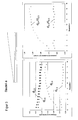
- FIG. 3 is the component a again, as it is already from the FIG. 2 shows schematically shown.
- the left graph now contains the measurement results showing the absolute layer thicknesses in ⁇ m on the vertical axis and the number of measuring positions on the horizontal axis.
- 19 equidistant lengths were defined from left to right, which were used as measuring points.
- the first and last measuring point at the start of the beam and the end of the beam were not recorded for metrological reasons. In other words, the first measured value took place after 110 ⁇ m, the last measured value 110 ⁇ m before the end of the bar.
- the absolute layer thicknesses are now shown for the individual measurement positions as described above.
- the absolute result for the component a is an absolute layer thickness of the coating on the side surface 2.3, ie on that side surface in which a constant gap was present, of about 3.4 ⁇ m.
- the layer thicknesses on the respective upper and lower sides, which have also been shown in the graph and designated separately, are almost constant and range between 5.0 ⁇ m and 5.5 ⁇ m.
- a gradually increasing layer thickness results on the side surface 2.4 of the component a.
- Figure 1d The same connection has already been made in Figure 1d ) described in detail.
- FIG. 5 is exemplified in the form of a silicon wafer 1, which serves as a substrate, shown how corresponding gap widths can be produced by structuring.
- x 1 b so that the first gap width for the first micromechanical component is shown and again with t, as already out Figure 1c ), the width of the component.
- x 2 , x 3 and x 4 then the other gap widths are determined.
- the individual micromechanical components are held by webs 5 in the substrate 1. With the help of such a structure, the general relationship between layer thickness and gap width ( Figure 1d )).
- FIG. 5 clarifies sustainably that in a very simple way by as in Figure 1d ) shown relationship between the aspect ratio and
- the coating thickness can be specifically realized different coating thicknesses on the side surfaces of the components according to the invention.
- a targeted influencing of the layer thicknesses and thus of reinforced areas on the side surfaces of micromechanical components is available.
- this reinforcement can only be selectively applied to individual areas of the side surfaces also entails a significant cost advantage.
- the micromechanical component according to the invention is thus characterized not only by the fact that improved targeted use properties result from the targeted reinforced regions of diamond or DLC, but at the same time great cost advantages are achieved by low material consumption and thin formation of the diamond layers on the points not arranged in the functional area can.
- FIG. 6 shows a further possibility in which again a uniform normalized layer thickness has been realized on the one side surface 2.3 and on the other side surface 2.4 a monotonically decreasing layer thickness in the right part and in the left part in a certain predetermined curve to the "target layer thickness" reducing layer thickness is selected by forming a corresponding gap.
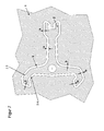
- FIG. 7 Now a clockwork component is shown in the form of an anchor, wherein the FIG. 5 shows a component according to the prior art, ie, a structuring, in which around the anchor member 2 a constant gap width b has been realized, as is conventional practice.
- the anchor will be back held by webs 5 in the substrate material 1. With 2.3 and 2.4 the side surfaces are described again.
- FIG. 8 an inventive design of such an anchor component, which is characterized in that in the highly stressed area a larger gap width b than in the prior art has been the case, has been selected.
- a larger gap width b than in the prior art has been the case, has been selected.
- an at least twice as large layer thickness of the diamond layer is thus achieved in the highly stressed region of the anchor component, as is customary in the prior art.
- the reinforced area is arranged only locally, namely at the points that are functionally related to another component, incurs lower costs, since the remaining layer thickness is in a thin version can be chosen.
- FIG. 9 another example is shown, in the form of a clockspring 2.
- the clockspring 2 is in turn held by webs 5 in a silicon wafer, which acts as a substrate 1.
- the gap width b is chosen so that this gap width widened continuously from the central center 3 from the end point of the spring 5 out.
- a spring is obtained which, due to the different coating thickness, which widens continuously towards the end point, has an optimum gait behavior.
- FIG. 10 now shows the relationship between the roughness rms in nm with the layer thickness in microns.
- the layer thickness is related to the roughness rms. This opens up additional possibilities to further optimize the coating 6 by virtue of the fact that, as a result of the relationship between the coating and the coating 6 FIG. 10 is shown, it is possible to modulate on a side surface not only the coating 6 so that a reinforced area is formed, but that one and the same surface depending on the thickness has different roughnesses.
- FIG. 1 surfaces with a very small layer thickness also show a very fine roughness, whereas surface areas, which then have an increased layer thickness, also have a greater degree of roughness in rms. As a result, there is an additional possibility of influencing the surface design of the side surfaces, so that thereby the component according to the invention can be additionally optimized.
Landscapes
- Engineering & Computer Science (AREA)
- Physics & Mathematics (AREA)
- General Physics & Mathematics (AREA)
- Manufacturing & Machinery (AREA)
- Metallurgy (AREA)
- Mechanical Engineering (AREA)
- Microelectronics & Electronic Packaging (AREA)
- Computer Hardware Design (AREA)
- Chemical Vapour Deposition (AREA)
- Crystals, And After-Treatments Of Crystals (AREA)
- Micromachines (AREA)
Priority Applications (2)
| Application Number | Priority Date | Filing Date | Title |
|---|---|---|---|
| EP11003088.9A EP2511229B1 (fr) | 2011-04-12 | 2011-04-12 | Composant micromécanique doté de flancs renforcés |
| US13/445,519 US9227834B2 (en) | 2011-04-12 | 2012-04-12 | Edge-reinforced micromechanical component |
Applications Claiming Priority (1)
| Application Number | Priority Date | Filing Date | Title |
|---|---|---|---|
| EP11003088.9A EP2511229B1 (fr) | 2011-04-12 | 2011-04-12 | Composant micromécanique doté de flancs renforcés |
Publications (2)
| Publication Number | Publication Date |
|---|---|
| EP2511229A1 true EP2511229A1 (fr) | 2012-10-17 |
| EP2511229B1 EP2511229B1 (fr) | 2017-03-08 |
Family
ID=44658513
Family Applications (1)
| Application Number | Title | Priority Date | Filing Date |
|---|---|---|---|
| EP11003088.9A Active EP2511229B1 (fr) | 2011-04-12 | 2011-04-12 | Composant micromécanique doté de flancs renforcés |
Country Status (2)
| Country | Link |
|---|---|
| US (1) | US9227834B2 (fr) |
| EP (1) | EP2511229B1 (fr) |
Cited By (6)
| Publication number | Priority date | Publication date | Assignee | Title |
|---|---|---|---|---|
| EP2735540A1 (fr) | 2012-11-22 | 2014-05-28 | Diamaze Microtechnology S.A. | Composant micromécanique composite ayant un revêtement, son procédé de fabrication et son utilisation |
| DE202014005288U1 (de) | 2013-06-27 | 2014-07-11 | Nivarox-Far S.A. | Uhrfeder aus austenitischem Edelstahl |
| EP2924514A1 (fr) | 2014-03-24 | 2015-09-30 | Nivarox-FAR S.A. | Ressort d'horlogerie en acier inoxydable austénitique |
| EP2889703A3 (fr) * | 2013-12-05 | 2015-09-30 | TGM Developpement SA | Procédé de fabrication d'une pièce mécanique en diamant pour mouvement de montre, et pièce fabriquée selon ce procédé |
| EP2889702A3 (fr) * | 2013-12-05 | 2015-10-07 | TGM Developpement SA | Palette d'ancre pour échappement de mouvement de montre, et procédé de fabrication adapté |
| WO2016135679A1 (fr) | 2015-02-27 | 2016-09-01 | Cartier International Ag | Ressort moteur dans un materiau composite a matrice metallique |
Families Citing this family (10)
| Publication number | Priority date | Publication date | Assignee | Title |
|---|---|---|---|---|
| US9958830B2 (en) * | 2011-07-21 | 2018-05-01 | The Swatch Group Research And Development Ltd | Functional micromechanical assembly |
| CH705944A2 (fr) * | 2011-12-22 | 2013-06-28 | Swatch Group Res & Dev Ltd | Procédé de réalisation d'un composant et composant horloger fabriqué par un tel procédé |
| EP2728300B1 (fr) * | 2012-10-31 | 2016-03-23 | Diamaze Coating Technology GmbH | Palpeur |
| EP2757423B1 (fr) * | 2013-01-17 | 2018-07-11 | Omega SA | Pièce pour mouvement d'horlogerie |
| CH708827A2 (fr) * | 2013-11-08 | 2015-05-15 | Nivarox Sa | Pièce de micromécanique creuse, à plusieurs niveaux fonctionnels et monobloc en un matériau à base d'un allotrope synthétique du carbone. |
| EP2937311B1 (fr) * | 2014-04-25 | 2019-08-21 | Rolex Sa | Procédé de fabrication d'un composant horloger renforcé, composant horloger et pièce d'horlogerie correspondants |
| EP2942147B1 (fr) * | 2014-05-08 | 2018-11-21 | Nivarox-FAR S.A. | Mécanisme d'échappement d'horlogerie sans lubrification |
| EP2945025B1 (fr) * | 2014-05-16 | 2018-02-07 | Nivarox-FAR S.A. | Mécanisme d'horlogerie à couple de contact sans lubrification |
| EP3002637B1 (fr) | 2014-09-29 | 2018-11-28 | Richemont International S.A. | Système horloger avec des propriétés tribologiques améliorées |
| EP3663867A1 (fr) | 2018-12-05 | 2020-06-10 | Cartier International AG | Ressort spiral compensateur pour un mouvement de montre ou d'horloge fabriqué à partir d'un alliage niobium-molybdène |
Citations (4)
| Publication number | Priority date | Publication date | Assignee | Title |
|---|---|---|---|---|
| DE102004052068A1 (de) | 2004-10-26 | 2006-04-27 | GFD-Gesellschaft für Diamantprodukte mbH | Schneidwerkzeug, Verfahren zu seiner Herstellung und dessen Verwendung |
| DE102008041778A1 (de) | 2007-09-07 | 2009-03-12 | Patek, Philippe | Zugfeder für Federhaus eines Uhrwerks mit erhöhter Gangdauer |
| DE102008061182A1 (de) * | 2008-12-04 | 2010-06-10 | Konrad Damasko | Verfahren zum Herstellen eines Mikrobauteils |
| EP2236455A1 (fr) * | 2009-04-02 | 2010-10-06 | GFD Gesellschaft für Diamantprodukte mbH | Composant micromécanique avec une usure réduite |
Family Cites Families (14)
| Publication number | Priority date | Publication date | Assignee | Title |
|---|---|---|---|---|
| US3661526A (en) * | 1969-06-24 | 1972-05-09 | Univ Case Western Reserve | Process for the catalytic growth of metastable crystals from the vapor phase |
| US5082359A (en) * | 1989-11-28 | 1992-01-21 | Epion Corporation | Diamond films and method of growing diamond films on nondiamond substrates |
| CA2031098A1 (fr) * | 1990-01-16 | 1991-07-17 | William F. Banholzer | Elements annulaires diamantes par procede chimique de depot en phase vapeur et methode de fabrication correspondante |
| US5366556A (en) * | 1992-01-10 | 1994-11-22 | Robert Prince | Process and apparatus for production of diamond-like films |
| US5317938A (en) * | 1992-01-16 | 1994-06-07 | Duke University | Method for making microstructural surgical instruments |
| US5571616A (en) * | 1995-05-16 | 1996-11-05 | Crystallume | Ultrasmooth adherent diamond film coated article and method for making same |
| US6769969B1 (en) * | 1997-03-06 | 2004-08-03 | Keltech Engineering, Inc. | Raised island abrasive, method of use and lapping apparatus |
| US6202772B1 (en) * | 1998-06-24 | 2001-03-20 | Smith International | Cutting element with canted design for improved braze contact area |
| CN1418295A (zh) * | 2000-07-11 | 2003-05-14 | 精工爱普生株式会社 | 弹簧、驱动机构以及应用这种弹簧的装置和时计 |
| US20070235230A1 (en) * | 2005-12-20 | 2007-10-11 | Bruno Cuillier | PDC cutter for high compressive strength and highly abrasive formations |
| EP2719794B1 (fr) * | 2007-01-22 | 2018-08-22 | Element Six Technologies Limited | Gravure au plasma de surfaces de diamant |
| CH699109A1 (fr) * | 2008-07-10 | 2010-01-15 | Swatch Group Res & Dev Ltd | Procédé de fabrication d'une pièce micromécanique. |
| EP2334841A4 (fr) * | 2008-09-12 | 2013-07-17 | Univ Brigham Young | Films contenant un gaz oxygéné infusé et leurs procédés de préparation |
| WO2010088891A2 (fr) * | 2009-02-06 | 2010-08-12 | Konrad Damasko | Système oscillant mécanique pour montres et élément fonctionnel pour montres |
-
2011
- 2011-04-12 EP EP11003088.9A patent/EP2511229B1/fr active Active
-
2012
- 2012-04-12 US US13/445,519 patent/US9227834B2/en active Active
Patent Citations (4)
| Publication number | Priority date | Publication date | Assignee | Title |
|---|---|---|---|---|
| DE102004052068A1 (de) | 2004-10-26 | 2006-04-27 | GFD-Gesellschaft für Diamantprodukte mbH | Schneidwerkzeug, Verfahren zu seiner Herstellung und dessen Verwendung |
| DE102008041778A1 (de) | 2007-09-07 | 2009-03-12 | Patek, Philippe | Zugfeder für Federhaus eines Uhrwerks mit erhöhter Gangdauer |
| DE102008061182A1 (de) * | 2008-12-04 | 2010-06-10 | Konrad Damasko | Verfahren zum Herstellen eines Mikrobauteils |
| EP2236455A1 (fr) * | 2009-04-02 | 2010-10-06 | GFD Gesellschaft für Diamantprodukte mbH | Composant micromécanique avec une usure réduite |
Non-Patent Citations (2)
| Title |
|---|
| R. DANZER ET AL.: "Technische keramische Werkstoffe", HVB VERLAG |
| R. MORRELL ET AL., INT. JOURNAL OF REFRACTORY METALS & HARD MATERIALS, vol. 28, 2010, pages 508 - 515 |
Cited By (8)
| Publication number | Priority date | Publication date | Assignee | Title |
|---|---|---|---|---|
| EP2735540A1 (fr) | 2012-11-22 | 2014-05-28 | Diamaze Microtechnology S.A. | Composant micromécanique composite ayant un revêtement, son procédé de fabrication et son utilisation |
| DE202014005288U1 (de) | 2013-06-27 | 2014-07-11 | Nivarox-Far S.A. | Uhrfeder aus austenitischem Edelstahl |
| WO2014206582A2 (fr) | 2013-06-27 | 2014-12-31 | Nivarox-Far S.A. | Ressort d'horlogerie en acier inoxydable austenitique |
| US10048649B2 (en) | 2013-06-27 | 2018-08-14 | Nivarox-Far S.A. | Timepiece spring made of austenitic stainless steel |
| EP2889703A3 (fr) * | 2013-12-05 | 2015-09-30 | TGM Developpement SA | Procédé de fabrication d'une pièce mécanique en diamant pour mouvement de montre, et pièce fabriquée selon ce procédé |
| EP2889702A3 (fr) * | 2013-12-05 | 2015-10-07 | TGM Developpement SA | Palette d'ancre pour échappement de mouvement de montre, et procédé de fabrication adapté |
| EP2924514A1 (fr) | 2014-03-24 | 2015-09-30 | Nivarox-FAR S.A. | Ressort d'horlogerie en acier inoxydable austénitique |
| WO2016135679A1 (fr) | 2015-02-27 | 2016-09-01 | Cartier International Ag | Ressort moteur dans un materiau composite a matrice metallique |
Also Published As
| Publication number | Publication date |
|---|---|
| US20120263909A1 (en) | 2012-10-18 |
| EP2511229B1 (fr) | 2017-03-08 |
| US9227834B2 (en) | 2016-01-05 |
Similar Documents
| Publication | Publication Date | Title |
|---|---|---|
| EP2511229B1 (fr) | Composant micromécanique doté de flancs renforcés | |
| EP2107434B1 (fr) | Chronomètre mécanique | |
| EP2037335B1 (fr) | Ancre pour échappement d'horlogerie | |
| EP2912207B1 (fr) | Composant doté d'un revêtement et procédé pour le fabriquer | |
| EP2727880B2 (fr) | Composant micromécanique tridimensionnel chanfreiné et son procédé de fabrication | |
| EP2236455B1 (fr) | Composant micromécanique avec une usure réduite | |
| AT505739B1 (de) | Zugfeder für federhaus eines uhrwerks mit erhöhter gangdauer | |
| EP3101484A1 (fr) | Systeme oscillant mecanique pour montres et procede de fabrication d'un systeme oscillant mecanique pour montres | |
| DE102011083714A1 (de) | Gleitelement mit DLC-Beschichtung | |
| EP2495081B1 (fr) | Outil de coupe doté d'une lame en diamant cristallin fin | |
| EP2735540B1 (fr) | Composant micromécanique composite ayant un revêtement, son procédé de fabrication et son utilisation | |
| DE60013264T2 (de) | Diamantbeschichtetes werkzeug | |
| EP3221492B1 (fr) | Matériau de lame | |
| DE4127639C2 (de) | Reibungsarme Verschleißschicht, ihre Verwendung und ihre Herstellung | |
| DE19716330C2 (de) | Verfahren zur Herstellung einer Beschichtung auf einem Schleifwerkzeug und Verwendung des Verfahrens | |
| EP2495080B1 (fr) | Outil de coupe doté d'une lame en diamant cristallin fin | |
| WO2015096882A2 (fr) | Revêtement doté d'une couche à base de mo‑n comprenant la phase delta du nitrure de molybdène | |
| EP3074550B1 (fr) | Revêtement doté d'une couche à base de mo-n comprenant la phase delta du nitrure de molybdène | |
| EP1381707B1 (fr) | Procede d'obtention d'un revetement sur un outil travaillant par enlevement de copeaux, et outil d'usinage par enlevement de copeaux y relatif | |
| WO2015125081A1 (fr) | Pièce micromécanique avec surface de contact réduite et son procédé de fabrication | |
| EP3001256A1 (fr) | Échappement à ancre | |
| DE102010006790A1 (de) | Mechanisches Schwingsystem für Uhren sowie Funktionselement für Uhren | |
| EP4180879A1 (fr) | Module micromécanique, son procédé de fabrication et son utilisation | |
| AT523638A4 (de) | Verfahren zur Herstellung einer Hartstoffschicht auf einer Metalloberfläche | |
| EP0662161B1 (fr) | Outil pour le traitement de surfaces d'elements de construction et substrat pour ledit outil |
Legal Events
| Date | Code | Title | Description |
|---|---|---|---|
| PUAI | Public reference made under article 153(3) epc to a published international application that has entered the european phase |
Free format text: ORIGINAL CODE: 0009012 |
|
| 17P | Request for examination filed |
Effective date: 20111206 |
|
| AK | Designated contracting states |
Kind code of ref document: A1 Designated state(s): AL AT BE BG CH CY CZ DE DK EE ES FI FR GB GR HR HU IE IS IT LI LT LU LV MC MK MT NL NO PL PT RO RS SE SI SK SM TR |
|
| AX | Request for extension of the european patent |
Extension state: BA ME |
|
| REG | Reference to a national code |
Ref country code: DE Ref legal event code: R079 Ref document number: 502011011766 Country of ref document: DE Free format text: PREVIOUS MAIN CLASS: B81C0001000000 Ipc: G04B0013020000 |
|
| RIC1 | Information provided on ipc code assigned before grant |
Ipc: B81B 3/00 20060101ALI20141031BHEP Ipc: G04B 17/06 20060101ALI20141031BHEP Ipc: G04B 13/02 20060101AFI20141031BHEP Ipc: G04B 1/14 20060101ALI20141031BHEP Ipc: G04B 15/14 20060101ALI20141031BHEP Ipc: B81C 1/00 20060101ALI20141031BHEP Ipc: G04B 31/004 20060101ALI20141031BHEP |
|
| 17Q | First examination report despatched |
Effective date: 20150925 |
|
| GRAP | Despatch of communication of intention to grant a patent |
Free format text: ORIGINAL CODE: EPIDOSNIGR1 |
|
| INTG | Intention to grant announced |
Effective date: 20160822 |
|
| GRAS | Grant fee paid |
Free format text: ORIGINAL CODE: EPIDOSNIGR3 |
|
| GRAJ | Information related to disapproval of communication of intention to grant by the applicant or resumption of examination proceedings by the epo deleted |
Free format text: ORIGINAL CODE: EPIDOSDIGR1 |
|
| GRAL | Information related to payment of fee for publishing/printing deleted |
Free format text: ORIGINAL CODE: EPIDOSDIGR3 |
|
| GRAR | Information related to intention to grant a patent recorded |
Free format text: ORIGINAL CODE: EPIDOSNIGR71 |
|
| GRAA | (expected) grant |
Free format text: ORIGINAL CODE: 0009210 |
|
| INTC | Intention to grant announced (deleted) | ||
| INTG | Intention to grant announced |
Effective date: 20170126 |
|
| AK | Designated contracting states |
Kind code of ref document: B1 Designated state(s): AL AT BE BG CH CY CZ DE DK EE ES FI FR GB GR HR HU IE IS IT LI LT LU LV MC MK MT NL NO PL PT RO RS SE SI SK SM TR |
|
| REG | Reference to a national code |
Ref country code: GB Ref legal event code: FG4D Free format text: NOT ENGLISH |
|
| REG | Reference to a national code |
Ref country code: CH Ref legal event code: EP Ref country code: AT Ref legal event code: REF Ref document number: 874065 Country of ref document: AT Kind code of ref document: T Effective date: 20170315 |
|
| REG | Reference to a national code |
Ref country code: IE Ref legal event code: FG4D Free format text: LANGUAGE OF EP DOCUMENT: GERMAN |
|
| REG | Reference to a national code |
Ref country code: DE Ref legal event code: R096 Ref document number: 502011011766 Country of ref document: DE |
|
| REG | Reference to a national code |
Ref country code: LT Ref legal event code: MG4D |
|
| REG | Reference to a national code |
Ref country code: NL Ref legal event code: MP Effective date: 20170308 |
|
| PG25 | Lapsed in a contracting state [announced via postgrant information from national office to epo] |
Ref country code: FI Free format text: LAPSE BECAUSE OF FAILURE TO SUBMIT A TRANSLATION OF THE DESCRIPTION OR TO PAY THE FEE WITHIN THE PRESCRIBED TIME-LIMIT Effective date: 20170308 Ref country code: NO Free format text: LAPSE BECAUSE OF FAILURE TO SUBMIT A TRANSLATION OF THE DESCRIPTION OR TO PAY THE FEE WITHIN THE PRESCRIBED TIME-LIMIT Effective date: 20170608 Ref country code: HR Free format text: LAPSE BECAUSE OF FAILURE TO SUBMIT A TRANSLATION OF THE DESCRIPTION OR TO PAY THE FEE WITHIN THE PRESCRIBED TIME-LIMIT Effective date: 20170308 Ref country code: GR Free format text: LAPSE BECAUSE OF FAILURE TO SUBMIT A TRANSLATION OF THE DESCRIPTION OR TO PAY THE FEE WITHIN THE PRESCRIBED TIME-LIMIT Effective date: 20170609 Ref country code: LT Free format text: LAPSE BECAUSE OF FAILURE TO SUBMIT A TRANSLATION OF THE DESCRIPTION OR TO PAY THE FEE WITHIN THE PRESCRIBED TIME-LIMIT Effective date: 20170308 |
|
| PG25 | Lapsed in a contracting state [announced via postgrant information from national office to epo] |
Ref country code: SE Free format text: LAPSE BECAUSE OF FAILURE TO SUBMIT A TRANSLATION OF THE DESCRIPTION OR TO PAY THE FEE WITHIN THE PRESCRIBED TIME-LIMIT Effective date: 20170308 Ref country code: RS Free format text: LAPSE BECAUSE OF FAILURE TO SUBMIT A TRANSLATION OF THE DESCRIPTION OR TO PAY THE FEE WITHIN THE PRESCRIBED TIME-LIMIT Effective date: 20170308 Ref country code: BG Free format text: LAPSE BECAUSE OF FAILURE TO SUBMIT A TRANSLATION OF THE DESCRIPTION OR TO PAY THE FEE WITHIN THE PRESCRIBED TIME-LIMIT Effective date: 20170608 Ref country code: LV Free format text: LAPSE BECAUSE OF FAILURE TO SUBMIT A TRANSLATION OF THE DESCRIPTION OR TO PAY THE FEE WITHIN THE PRESCRIBED TIME-LIMIT Effective date: 20170308 Ref country code: ES Free format text: LAPSE BECAUSE OF FAILURE TO SUBMIT A TRANSLATION OF THE DESCRIPTION OR TO PAY THE FEE WITHIN THE PRESCRIBED TIME-LIMIT Effective date: 20170308 |
|
| REG | Reference to a national code |
Ref country code: CH Ref legal event code: NV Representative=s name: TROESCH SCHEIDEGGER WERNER AG, CH |
|
| PG25 | Lapsed in a contracting state [announced via postgrant information from national office to epo] |
Ref country code: NL Free format text: LAPSE BECAUSE OF FAILURE TO SUBMIT A TRANSLATION OF THE DESCRIPTION OR TO PAY THE FEE WITHIN THE PRESCRIBED TIME-LIMIT Effective date: 20170308 |
|
| PG25 | Lapsed in a contracting state [announced via postgrant information from national office to epo] |
Ref country code: EE Free format text: LAPSE BECAUSE OF FAILURE TO SUBMIT A TRANSLATION OF THE DESCRIPTION OR TO PAY THE FEE WITHIN THE PRESCRIBED TIME-LIMIT Effective date: 20170308 Ref country code: IT Free format text: LAPSE BECAUSE OF FAILURE TO SUBMIT A TRANSLATION OF THE DESCRIPTION OR TO PAY THE FEE WITHIN THE PRESCRIBED TIME-LIMIT Effective date: 20170308 Ref country code: RO Free format text: LAPSE BECAUSE OF FAILURE TO SUBMIT A TRANSLATION OF THE DESCRIPTION OR TO PAY THE FEE WITHIN THE PRESCRIBED TIME-LIMIT Effective date: 20170308 Ref country code: CZ Free format text: LAPSE BECAUSE OF FAILURE TO SUBMIT A TRANSLATION OF THE DESCRIPTION OR TO PAY THE FEE WITHIN THE PRESCRIBED TIME-LIMIT Effective date: 20170308 Ref country code: SK Free format text: LAPSE BECAUSE OF FAILURE TO SUBMIT A TRANSLATION OF THE DESCRIPTION OR TO PAY THE FEE WITHIN THE PRESCRIBED TIME-LIMIT Effective date: 20170308 |
|
| PG25 | Lapsed in a contracting state [announced via postgrant information from national office to epo] |
Ref country code: SM Free format text: LAPSE BECAUSE OF FAILURE TO SUBMIT A TRANSLATION OF THE DESCRIPTION OR TO PAY THE FEE WITHIN THE PRESCRIBED TIME-LIMIT Effective date: 20170308 Ref country code: PT Free format text: LAPSE BECAUSE OF FAILURE TO SUBMIT A TRANSLATION OF THE DESCRIPTION OR TO PAY THE FEE WITHIN THE PRESCRIBED TIME-LIMIT Effective date: 20170710 Ref country code: IS Free format text: LAPSE BECAUSE OF FAILURE TO SUBMIT A TRANSLATION OF THE DESCRIPTION OR TO PAY THE FEE WITHIN THE PRESCRIBED TIME-LIMIT Effective date: 20170708 Ref country code: PL Free format text: LAPSE BECAUSE OF FAILURE TO SUBMIT A TRANSLATION OF THE DESCRIPTION OR TO PAY THE FEE WITHIN THE PRESCRIBED TIME-LIMIT Effective date: 20170308 |
|
| REG | Reference to a national code |
Ref country code: DE Ref legal event code: R097 Ref document number: 502011011766 Country of ref document: DE |
|
| PLBE | No opposition filed within time limit |
Free format text: ORIGINAL CODE: 0009261 |
|
| STAA | Information on the status of an ep patent application or granted ep patent |
Free format text: STATUS: NO OPPOSITION FILED WITHIN TIME LIMIT |
|
| REG | Reference to a national code |
Ref country code: IE Ref legal event code: MM4A |
|
| REG | Reference to a national code |
Ref country code: FR Ref legal event code: ST Effective date: 20171229 |
|
| PG25 | Lapsed in a contracting state [announced via postgrant information from national office to epo] |
Ref country code: FR Free format text: LAPSE BECAUSE OF NON-PAYMENT OF DUE FEES Effective date: 20170509 Ref country code: DK Free format text: LAPSE BECAUSE OF FAILURE TO SUBMIT A TRANSLATION OF THE DESCRIPTION OR TO PAY THE FEE WITHIN THE PRESCRIBED TIME-LIMIT Effective date: 20170308 Ref country code: MC Free format text: LAPSE BECAUSE OF FAILURE TO SUBMIT A TRANSLATION OF THE DESCRIPTION OR TO PAY THE FEE WITHIN THE PRESCRIBED TIME-LIMIT Effective date: 20170308 |
|
| 26N | No opposition filed |
Effective date: 20171211 |
|
| GBPC | Gb: european patent ceased through non-payment of renewal fee |
Effective date: 20170608 |
|
| PG25 | Lapsed in a contracting state [announced via postgrant information from national office to epo] |
Ref country code: LU Free format text: LAPSE BECAUSE OF NON-PAYMENT OF DUE FEES Effective date: 20170412 Ref country code: SI Free format text: LAPSE BECAUSE OF FAILURE TO SUBMIT A TRANSLATION OF THE DESCRIPTION OR TO PAY THE FEE WITHIN THE PRESCRIBED TIME-LIMIT Effective date: 20170308 |
|
| REG | Reference to a national code |
Ref country code: BE Ref legal event code: MM Effective date: 20170430 |
|
| PG25 | Lapsed in a contracting state [announced via postgrant information from national office to epo] |
Ref country code: GB Free format text: LAPSE BECAUSE OF NON-PAYMENT OF DUE FEES Effective date: 20170608 Ref country code: IE Free format text: LAPSE BECAUSE OF NON-PAYMENT OF DUE FEES Effective date: 20170412 |
|
| PG25 | Lapsed in a contracting state [announced via postgrant information from national office to epo] |
Ref country code: BE Free format text: LAPSE BECAUSE OF NON-PAYMENT OF DUE FEES Effective date: 20170430 |
|
| REG | Reference to a national code |
Ref country code: AT Ref legal event code: MM01 Ref document number: 874065 Country of ref document: AT Kind code of ref document: T Effective date: 20170412 |
|
| PG25 | Lapsed in a contracting state [announced via postgrant information from national office to epo] |
Ref country code: AT Free format text: LAPSE BECAUSE OF NON-PAYMENT OF DUE FEES Effective date: 20170412 |
|
| PG25 | Lapsed in a contracting state [announced via postgrant information from national office to epo] |
Ref country code: MT Free format text: LAPSE BECAUSE OF FAILURE TO SUBMIT A TRANSLATION OF THE DESCRIPTION OR TO PAY THE FEE WITHIN THE PRESCRIBED TIME-LIMIT Effective date: 20170308 |
|
| PG25 | Lapsed in a contracting state [announced via postgrant information from national office to epo] |
Ref country code: HU Free format text: LAPSE BECAUSE OF FAILURE TO SUBMIT A TRANSLATION OF THE DESCRIPTION OR TO PAY THE FEE WITHIN THE PRESCRIBED TIME-LIMIT; INVALID AB INITIO Effective date: 20110412 |
|
| PG25 | Lapsed in a contracting state [announced via postgrant information from national office to epo] |
Ref country code: CY Free format text: LAPSE BECAUSE OF NON-PAYMENT OF DUE FEES Effective date: 20170308 |
|
| PG25 | Lapsed in a contracting state [announced via postgrant information from national office to epo] |
Ref country code: MK Free format text: LAPSE BECAUSE OF FAILURE TO SUBMIT A TRANSLATION OF THE DESCRIPTION OR TO PAY THE FEE WITHIN THE PRESCRIBED TIME-LIMIT Effective date: 20170308 |
|
| PG25 | Lapsed in a contracting state [announced via postgrant information from national office to epo] |
Ref country code: TR Free format text: LAPSE BECAUSE OF FAILURE TO SUBMIT A TRANSLATION OF THE DESCRIPTION OR TO PAY THE FEE WITHIN THE PRESCRIBED TIME-LIMIT Effective date: 20170308 |
|
| PG25 | Lapsed in a contracting state [announced via postgrant information from national office to epo] |
Ref country code: AL Free format text: LAPSE BECAUSE OF FAILURE TO SUBMIT A TRANSLATION OF THE DESCRIPTION OR TO PAY THE FEE WITHIN THE PRESCRIBED TIME-LIMIT Effective date: 20170308 |
|
| P01 | Opt-out of the competence of the unified patent court (upc) registered |
Effective date: 20230525 |
|
| PGFP | Annual fee paid to national office [announced via postgrant information from national office to epo] |
Ref country code: DE Payment date: 20240416 Year of fee payment: 14 |
|
| PGFP | Annual fee paid to national office [announced via postgrant information from national office to epo] |
Ref country code: CH Payment date: 20240501 Year of fee payment: 14 |