EP2507592B1 - Handgasdrehgriff mit drehwinkel-messsystem - Google Patents
Handgasdrehgriff mit drehwinkel-messsystem Download PDFInfo
- Publication number
- EP2507592B1 EP2507592B1 EP10788252.4A EP10788252A EP2507592B1 EP 2507592 B1 EP2507592 B1 EP 2507592B1 EP 10788252 A EP10788252 A EP 10788252A EP 2507592 B1 EP2507592 B1 EP 2507592B1
- Authority
- EP
- European Patent Office
- Prior art keywords
- magnet
- sensor
- rotary handle
- segment
- manual gas
- Prior art date
- Legal status (The legal status is an assumption and is not a legal conclusion. Google has not performed a legal analysis and makes no representation as to the accuracy of the status listed.)
- Active
Links
- 230000004907 flux Effects 0.000 claims 1
- 238000001514 detection method Methods 0.000 description 2
- 238000004026 adhesive bonding Methods 0.000 description 1
- 238000006243 chemical reaction Methods 0.000 description 1
- 238000012937 correction Methods 0.000 description 1
- 238000013461 design Methods 0.000 description 1
- 238000011156 evaluation Methods 0.000 description 1
- 230000001939 inductive effect Effects 0.000 description 1
- 230000007774 longterm Effects 0.000 description 1
- 230000005415 magnetization Effects 0.000 description 1
- 238000004519 manufacturing process Methods 0.000 description 1
- 238000000691 measurement method Methods 0.000 description 1
- 238000013139 quantization Methods 0.000 description 1
Images

Classifications
-
- G—PHYSICS
- G01—MEASURING; TESTING
- G01D—MEASURING NOT SPECIALLY ADAPTED FOR A SPECIFIC VARIABLE; ARRANGEMENTS FOR MEASURING TWO OR MORE VARIABLES NOT COVERED IN A SINGLE OTHER SUBCLASS; TARIFF METERING APPARATUS; MEASURING OR TESTING NOT OTHERWISE PROVIDED FOR
- G01D5/00—Mechanical means for transferring the output of a sensing member; Means for converting the output of a sensing member to another variable where the form or nature of the sensing member does not constrain the means for converting; Transducers not specially adapted for a specific variable
- G01D5/12—Mechanical means for transferring the output of a sensing member; Means for converting the output of a sensing member to another variable where the form or nature of the sensing member does not constrain the means for converting; Transducers not specially adapted for a specific variable using electric or magnetic means
- G01D5/14—Mechanical means for transferring the output of a sensing member; Means for converting the output of a sensing member to another variable where the form or nature of the sensing member does not constrain the means for converting; Transducers not specially adapted for a specific variable using electric or magnetic means influencing the magnitude of a current or voltage
- G01D5/142—Mechanical means for transferring the output of a sensing member; Means for converting the output of a sensing member to another variable where the form or nature of the sensing member does not constrain the means for converting; Transducers not specially adapted for a specific variable using electric or magnetic means influencing the magnitude of a current or voltage using Hall-effect devices
- G01D5/145—Mechanical means for transferring the output of a sensing member; Means for converting the output of a sensing member to another variable where the form or nature of the sensing member does not constrain the means for converting; Transducers not specially adapted for a specific variable using electric or magnetic means influencing the magnitude of a current or voltage using Hall-effect devices influenced by the relative movement between the Hall device and magnetic fields
Definitions
- the invention relates to a hand throttle grip with a sensor arrangement, designed to detect the movement of an element, in particular designed to detect the rotation of a shaft, comprising a movable magnet through the element and a sensor, designed to detect the movement of the magnet.
- contactless-acting sensor arrangements in particular rotational-angle sensors, based on inductive, capacitive, resistive and hall-based systems are already known, in particular for hand throttle grips of vehicles, but also for the detection of translatory movements.
- Hall rotation angle systems differ in hollow shaft systems and systems which must be mounted on the end (stub) of the shaft.
- the invention has for its object to develop a non-contact sensor arrangement, which drastically reduces the disadvantages of previous systems with respect to external field influences and significantly increases the resolution.
- the invention provides that the magnet is subdivided into three magnet segments, each magnet segment having its own north and south pole. Contrary to usual bipolar magnets, which only a single Have north and south pole, in the sensor arrangement according to the invention, three segments, ie three poles of the magnet, used to measure the position of the movable element. This causes in an advantageous manner that z. B. from a rotational movement of only 90 degrees, the field lines of the magnet can describe an angle change of up to 360 degrees, which can be detected with the sensor and then evaluated.
- the decisive advantage here is that already the raw or useful signal for the user data generation can be correspondingly resolved exactly.
- the sensor arrangement (measuring system) according to the invention is tolerant to temperature or age related drift of the magnet due to the preferably used differential measurement method.
- the invention provides for the sensor to be arranged outside the magnet and, when the magnet moves, directly opposite the magnetic poles of the respective magnet segment and in the main flow direction of the magnetic field lines.
- the sensor ie, the magnetically sensitive element (preferably a Hall sensor) directly on the outer diameter and thus is directly opposite the magnetic poles of the magnet.
- the magnet can be manufactured as a separate component and then attached to the rotatable or displaceable element.
- the magnet is already integrated with the production of the movable element on or in this and thus is a part of the movable element.
- the sensor arrangement according to the invention is used for detecting rotational movements in a hollow shaft system, but besides systems can also be used, in which the sensor arrangement is mounted on the stub shaft.
- the FIG. 1 shows, as far as shown in detail, a sensor assembly 1, which is used in a hollow shaft system used.
- the sensor arrangement or the hollow shaft system shown comprises a shaft 2 whose rotational movement (rotational movement) is to be detected by means of the sensor arrangement 1.
- a magnet 3 is arranged on the shaft 2.
- the sensor arrangement 1 comprises a sensor 4, that is, a magneto-sensitive element such.
- the sensor arrangement 1 comprises an unspecified plug-in device with which the raw signals of the sensor 4 are delivered in a suitable form to a downstream evaluation or control device (in the case of a manual throttle twist grip, eg an e-gas system).
- a manual throttle twist grip eg an e-gas system
- FIG. 1 shown system configured so that the hand throttle grip is rotatable by an operator between two stops and one of the stops defines the starting position from which the hand throttle grip 5 can be unscrewed by the operator.
- This rotational movement takes place against the force of a spring, which is designed as a return spring, so that the hand throttle grip 5 is automatically moved back to its starting position (idling) without the action of force by the operator.
- the magnet 3 has a round shape and the movable member is the shaft 2, wherein the magnet 3 is arranged and fixed on the shaft 2 and further wherein the sensor 4 is disposed directly adjacent to the outer periphery of the magnet 3.
- the sensor assembly 1 is pulled apart illustratively together with the hand throttle grip 5 in order to represent and recognize the individual components.
- the magnet 3 is designed as a disk, wherein the disk has a bore, through which the shaft 2 is guided, so that the magnet 3 can be arranged on the shaft 2 and fastened (eg adhesively bonded).
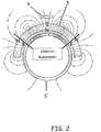
- the sensor 4 is arranged outside of the magnet 3 and in movement of the magnet 3 in each case directly opposite the magnetic poles of the respective magnet segment and is in the main flow direction of the magnetic field lines is on the FIG. 2 directed.
- the magnet 3 has exactly 3 magnet segments, each magnet segment having its own north and south pole N, S.
- the hand throttle 5 (handle) is shown schematically and in section with. Due to the rotational movement of the hand throttle grip 5, the magnet 3 shown is rotated with its at least 3 magnet segments with respect to the stationary sensor 4, so that the marked poles N, S of the respective magnet segment of the magnet 3 between the effective effective range (and possibly beyond) can move.
- magnet 3 with its exactly 3 magnet segments, this magnet 3 is annular, may be integrally formed as well as a disc-shaped magnet for detecting rotational movements or a longitudinally extending magnet for detecting translational movements, be part of the movable element be composed of several individual or separately produced magnetic segments. So z. B. for the realization of the annular magnet 3 according to FIG.
- individual ring segment magnets with one pole for example a ring segment magnet with a north pole lying on the outer circumference and two ring segment magnets with a south pole lying on the outer circumference (or vice versa) are produced and produced in a suitable manner (eg by gluing the like) a magnet extending along a direction of movement (reciprocation) which may also be suitably formed of a plurality of individual magnet segments having their own poles alternating in the direction of movement.
- the embodiment of the sensor arrangement 1 according to the FIGS. 1 and 2 are perpendicular to the direction of movement (when viewing the FIG. 2 a rotational movement about the longitudinal axis of the hand throttle grip 5) recorded magnetic components in one and the at least further direction (in particular the X and Z directions) of the magnetic field lines B (in particular Bx and Bz) for calculating the actual position of the hand throttle 5 based on its initial position) are used as absolute value. That means, that the position of the magnet 3 with respect to the sensor 4 can be mathematically deduced from the function of arctangent from Bx to Bz.
- the present invention thus realizes the advantages that few components are required for the sensor assembly 1 and this can be calibrated after their assembly.
- lengths translatorsichen movements up to 400 mm at a resolution of 0.1 mm can be realized.
- the cost-effective manufacturability and the long-term stability with simultaneous reduction of the external field influences and significant increase in the resolution should be mentioned as an advantage.
- This also applies analogously to a sensor arrangement 1 which is suitable for detecting rotational movements (in particular according to the exemplary embodiment) FIG. 1 and 2 ) is trained.
- the inventive sensor arrangement for the detection of rotational movements is applied, in which the angle of rotation is ⁇ 360 degrees.
Description
- Die Erfindung betrifft einen Handgasdrehgriff mit einer Sensoranordnung, ausgebildet zur Erfassung der Bewegung eines Elementes, insbesondere ausgebildet zur Erfassung der Rotation einer Welle, aufweisend einen durch das Element bewegbaren Magnet sowie einen Sensor, ausgebildet zur Erfassung der Bewegung des Magneten.
- Aus dem Stand der Technik sind bereits insbesondere für Handgasdrehgriffe von Fahrzeugen, aber auch für die Erfassung translatorischer Bewegungen, berührungslos wirkende Sensoranordnungen, insbesondere Drehwinkelsensoren, auf Basis induktiver, kapazitiver, resistiver und hallbasierter Systeme bekannt. Hall-Drehwinkelsysteme unterscheiden sich in Hohlwellensysteme und Systeme, welche an dem Ende (Stumpf) der Welle montiert werden müssen.
- Der Erfindung liegt die Aufgabe zugrunde, eine berührungslos wirkende Sensoranordnung zu entwickeln, welche die Nachteile bisherige Systeme bezüglich Fremdfeldeinflüsse drastisch reduziert und die die Auflösung deutlich erhöht.
- Diese Aufgabe ist durch die Merkmale des Patentanspruches 1 gelöst.
- Einerseits ist erfindungsgemäß vorgesehen, dass der Magnet in drei Magnetsegmente unterteilt ist, wobei jedes Magnetsegment einen eigenen Nord- und Südpol aufweist. Entgegen üblichen zweipoligen Magneten, die nur einen einzigen Nord- und Südpol aufweisen, werden bei der erfindungsgemäßen Sensoranordnung drei Segmente, d. h. drei Pole des Magneten, zur Messung der Position des bewegbaren Elementes genutzt. Dies bewirkt in vorteilhafter Weise, dass z. B. aus einer Drehbewegung von nur 90 Grad die Feldlinien des Magneten eine Winkeländerung von bis zu 360 Grad beschreiben können, die mit dem Sensor erfasst und anschließend ausgewertet werden kann. Der entscheidende Vorteil dabei ist, dass bereits das Roh- bzw. Nutzsignal für die Nutzdatengenerierung entsprechend genau aufgelöst werden kann. Denn bisher bekannte handelsübliche Systeme können bei einer 90 Grad-Magnetwinkeländerung nur eine Auflösung von 12 Bit nutzen, was bei den nachfolgenden Linearisierungen, Skalierungen und Datenwandlungen des Rohsignales mit ebenfalls einer Auflösung von 12 Bit zu mehrmaligen Quantisierungsfehlern führt. Im Gegensatz hierzu können die senkrecht zur Bewegungsrichtung (translatorisch oder rotatorisch) aufgenommenen magnetischen Anteile, d. h. der Feldlinien in X- und in Z-Richtung, zur Berechnung der tatsächlichen Position als Absolutwert herangezogen werden. Vereinfacht kann gesagt werden, dass aus der Funktion Arcustangens (Bx/Bz) auf die Position des Magneten geschlossen werden kann. Hierbei können noch zur Linearisierung weitere Korrekturfaktoren einbezogen werden. Die erfindungsgemäße Sensoranordnung (Messsystem) ist aufgrund des vorzugsweise eingesetzten differenziellen Messverfahrens tolerant gegen temperatur- oder altersbezogene Drift des Magneten.
- Weiterhin ist erfindungsgemäß vorgesehen, dass der Sensor außerhalb des Magneten und bei Bewegung des Magneten jeweils direkt gegenüber den magnetischen Polen des jeweiligen Magnetsegmentes angeordnet ist und sich in der Hauptflussrichtung der Magnetfeldlinien befindet. Bei einer Sensoranordnung zur Erfassung rotatorischer Bewegungen eines Elementes befindet sich somit der Sensor, d. h. das magnetisch sensitive Element (vorzugsweise ein Hallsensor) direkt am Außendurchmesser und steht somit direkt gegenüber den magnetischen Polen des Magnetes. Aus der Magnetisierrichtung des Magneten und der Sensoranordnung ergibt sich gegenüber bekannten Anordnungen ein wesentlich vergrößerter Nutz-/Störabstand, da bei den bestehenden bekannten Systemen sich die Sensoren im Nebenfluss (Nebenflussrichtung) der Magnetfeldlinien befinden. Diese sind damit wesentlich störempfindlicher gegen Fremdfelder. D. h., daß mit dieser Anordnung des Sensors in der Hauptflussrichtung der Magnetfeldlinien Fremdeinflüsse wesentlich reduziert werden können.
- Die vorstehende Erläuterung der Erfindung gilt für Sensoranordnungen, die entweder translatorische Bewegungen (Hin- und Herbewegung) oder rotatorische Bewegungen ausführen. Bei der konstruktiven Ausgestaltung einer solchen Sensoranordnung kann der Magnet als separates Bauteil hergestellt und anschließend an dem drehbeweglichen oder verschiebbaren Element befestigt werden. Alternativ dazu ist es denkbar, dass der Magnet schon mit Herstellung des bewegbaren Elementes an oder in diesem integriert ist und somit ein Bestandteil des bewegbaren Elementes ist. Ebenso wird in besonders bevorzugter Weise die erfindungsgemäße Sensoranordnung zur Erfassung rotatorischer Bewegungen in einem Hohlwellensystem eingesetzt, wobei daneben aber auch Systeme zu Einsatz kommen können, bei denen die Sensoranordnung am Wellenstumpf montiert ist.
- Ein besonders bevorzugtes Ausführungsbeispiel, auf das die Erfindung jedoch nicht beschränkt ist, ist im Folgenden erläutert und in den
Figuren 1 und2 dargestellt. - Die
Figur 1 zeigt, soweit im Einzelnen dargestellt, eine Sensoranordnung 1, die in einem Hohlwellensystem zum Einsatz kommt. Die Sensoranordnung bzw. das gezeigte Hohlwellensystem umfasst eine Welle 2, deren Rotationsbewegung (Drehbewegung) mittels der Sensoranordnung 1 erfasst werden soll. Hierzu ist auf der Welle 2 ein Magnet 3 angeordnet. Eine mögliche Anordnung des Magneten 3 ist inFigur 2 gezeigt. Weiterhin umfasst die Sensoranordnung 1 einen Sensor 4, also ein magnetosensitives Element wie z. B. ein Hallsensor (im Falle einer gewünschten Redundanz sind auch zwei oder ggfs. auch mehr als zwei Sensoren einsetzbar). - Mit der in
Figur 1 gezeigten Sensoranordnung 1 soll die rotatorische Bewegung eines Handgasdrehgriffes 5 eines Fahrzeuges, wie z. B. eines Motorrades, erfasst werden. Weiterhin umfasst die Sensoranordnung 1 eine nicht näher bezeichnete Steckvorrichtung, mit der die Rohsignale des Sensors 4 in geeigneter Form an eine nachgeschaltete Auswerte- bzw. Steuervorrichtung (bei einem Handgasdrehgriff z. B. ein E-Gassystem) abgegeben werden. Außerdem ist das inFigur 1 gezeigte System so ausgestaltet, dass der Handgasdrehgriff von einer Bedienperson zwischen zwei Anschlägen drehbewegbar ist und einer der Anschläge die Ausgangsposition definiert, aus welcher der Handgasdrehgriff 5 von der Bedienperson herausgedreht werden kann. Diese Drehbewegung erfolgt gegen die Kraft einer Feder, die als Rückstellfeder ausgebildet ist, sodass der Handgasdrehgriff 5 ohne Krafteinwirkung der Bedienperson in seine Ausgangsstellung (Leerlauf) automatisch zurückbewegt wird. - Somit ist in dem Ausführungsbeispiel gemäß
Figur 1 erkennbar, dass der Magnet 3 eine runde Bauform aufweist und das bewegbare Element die Welle 2 ist, wobei der Magnet 3 auf der Welle 2 angeordnet und befestigt ist und wobei weiterhin der Sensor 4 direkt benachbart zum Außenumfang des Magneten 3 angeordnet ist. Dabei ist bei Betrachtung derFigur 1 zu berücksichtigen, dass die Sensoranordnung 1 zusammen mit dem Handgasdrehgriff 5 darstellerisch auseinandergezogen ist, um die einzelnen Bauteile darstellen und erkennen zu können. Nach dem Zusammenbau sind die Bauelemente der Sensoranordnung 1, insbesondere der Magnet 3 und der Sensor 4 (einschließlich eine Steckverbindung) in einem Gehäuse 6 der Sensoranordnung 1 untergebracht, die sich an dem einen Ende des Handgasdrehgriffes 5 befindet. - Bei dem Ausführungsbeispiel gemäß
Figur 1 ist der Magnet 3 als Scheibe ausgebildet, wobei die Scheibe eine Bohrung aufweist, durch die die Welle 2 geführt ist, damit der Magnet 3 auf der Welle 2 angeordnet und befestigt (z. B. verklebt) werden kann. - Alternativ dazu und zur Erläuterung, dass der Sensor 4 außerhalb des Magneten 3 und bei Bewegung des Magnet 3 jeweils direkt gegenüber den magnetischen Polen des jeweiligen Magnetsegmentes angeordnet ist und sich in der Hauptflussrichtung der Magnetfeldlinien befindet, wird auf die
Figur 2 verwiesen. InFigur 2 ist erkennbar, dass der Magnet 3 genau 3 Magnetsegmente aufweist, wobei jedes Magnetsegment einen eigenen Nord- und Südpol N, S aufweist. Zum Verständnis der Anordnung ist auch der Handgasgriff 5 (Griffrohr) schematisch und im Schnitt mit eingezeichnet. Durch die Drehbewegung des Handgasdrehgriffes 5 wird der dargestellte Magnet 3 mit seinen zumindest 3 Magnetsegmenten in Bezug auf den feststehenden Sensor 4 drehbewegt, sodass sich die eingezeichneten Pole N, S des jeweiligen Magnetsegmentes des Magnetes 3 zwischen dem effektiven Nutzbereich (und ggf. darüber hinaus) bewegen können. Diese Drehbewegung wird in vorteilhafter Weise derart von dem Sensor 4 erfasst, dass sich einerseits das magnetisch sensitive Element direkt am Außendurchmesser befindet und somit direkt gegenüber den magnetischen Polen steht und andererseits der Sensor 4 sich in der Hauptflussrichtung der dargstellten Magnetfeldlinien befindet, wobei aus dieser Magnetisierrichtung und der gezeigten Anordnung des Sensors 4 sich ein deutlich vergrößerter Nutz-/Störabstand im Vergleich zu bekannten Systemen einstellt, da der Sensor bei bekannten Systemen sich im Nebenfluss der Magnetfeldlinien befindet und eine derartige Sensoranordnung damit wesentlich störempfindlicher gegen Fremdfelder ist. - Der in
Figur 2 gezeigte Magnet 3 mit seinen genau 3 Magnetsegmenten, wobei dieser Magnet 3 ringförmig ausgebildet ist, kann, ebenso wie ein scheibenförmig ausgebildeter Magnet zur Erfassung von Drehbewegungen oder ein sich länglich erstreckender Magnet zur Erfassung von translatorischen Bewegungen einstückig ausgebildet sein, Bestandteil des bewegbaren Elementes sein oder aus mehreren einzelnen oder separat voneinander hergestellten Magnetsegmenten zusammengesetzt sein. So können z. B. zur Realisierung des ringförmigen Magneten 3 gemäßFigur 2 einzelne Ringsegmentmagnete mit einen Polen (so beispielsweise ein Ringsegmentmagnet mit am Außenumfang liegendem Nordpol sowie zwei Ringsegmentmagnete mit am Außenumfang liegendem Südpol (oder umgekehrt) hergestellt und in geeigneter Weise (z. B. durch Verkleben der dergleichen) hergestellt werden. Gleiches gilt selbstverständlich auch für einen sich längs einer Bewegungsrichtung (Hin- und Herbewegung) erstreckenden Magneten, der ebenso in geeigneter Form aus mehreren einzelnen Magnetsegmenten mit eigenen, sich in Bewegungsrichtung abwechselnden Polen ausgebildet sein kann. - Im dargestellten Beispiel der Ausführungsform der Sensoranordnung 1 gemäß der
Figuren 1 und2 , insbesondere des ringförmig gestalteten Magnetes 3, werden die senkrecht zur Bewegungsrichtung (bei Betrachtung derFigur 2 eine Drehbewegung um die Längsachse des Handgasdrehgriffes 5 herum) aufgenommenen magnetischen Anteile in der einen und der zumindest weiteren Richtung (insbesondere der X- und der Z-Richtung) der Magnetfeldlinien B (insbesondere Bx und Bz) zur Berechnung der tatsächlichen Position des Handgasgriffes 5 (bezogen auf seine Ausgangsposition) als Absolutwert herangezogen werden. Das bedeutet, dass rechnerisch aus der Funktion von Arcustangens von Bx zu Bz auf die Position des Magneten 3 in Bezug auf den Sensor 4 geschlossen werden kann. - Zusammenfassend realisiert die vorliegende Erfindung also die Vorteile, dass wenige Bauteile für die Sensoranordnung 1 erforderlich sind und diese nach ihrem Zusammenbau kalibrierbar ist. Außerdem sind Längen bei translatorsichen Bewegungen bis zu 400 mm bei einer Auflösung von 0,1 mm realisierbar. Außerdem ist als Vorteil die kostengünstige Herstellbarkeit sowie die Langzeitstabilität bei gleichzeitiger Verringerung der Fremdfeldeinflüsse und deutliche Steigerung der Auflösung zu nennen. Dies gilt analog dazu auch für eine Sensoranordnung 1, die zur Erfassung rotatorischer Bewegungen (insbesondere gemäß dem Ausführungsbeispiel entsprechend
Figur 1 und2 ) ausgebildet ist. - Die wird erfindungsgemäße Sensoranordnung für die Erfassung von rotatorischen Bewegungen angewendet, bei denen der Drehwinkel < 360 Grad beträgt.
Claims (3)
- Handgasdrehgriff (5) mit einer Sensoranordnung (1), ausgebildet zur Erfassung der Bewegung einer Welle (2) des Handgasdrehgriffes (5), aufweisend einen durch die Welle (2) bewegbaren Magnet (3) sowie einen Sensor (4), ausgebildet zur Erfassung der Bewegung des Magneten (3), wobei der Handgasdrehgriff (5) zwischen zwei Anschlägen über einen Drehwinkel kleiner 360 Grad drehbewegbar ist, dadurch gekennzeichnet, dass der Magnet (3) in genau drei Magnetsegmente unterteilt ist, wobei jedes Magnetsegment einen eigenen Nord- und Südpol (N, S) aufweist, dass der Sensor (4) außerhalb des Magneten (3) und bei Bewegung des Magneten (3) jeweils direkt gegenüber den magnetischen Polen des jeweiligen Magnetsegmentes angeordnet ist und sich in der Hauptflußrichtung der Magnetfeldlinien befindet, wobei ein Magnetsegment mit am Aussenumfang liegendem Nordpol sowie jeweils daneben ein Magnetsegment mit am Aussenumfang liegendem Südpol oder ein Magnetsegment mit am Aussenumfang liegendem Südpol sowie jeweils daneben ein Magnetsegment mit am Aussenumfang liegendem Nordpol angeordnet sind, und wobei der Drehwinkel des Handgasdrehgriffes (5) in einem Bereich zwischen der Mitte des einen äusseren Magnetsegmentes und der Mitte des anderen äusseren Magnetsegmentes begrenzt ist, und wobei die zwei Anschläge innerhalb dieses Bereiches angeordnet sind.
- Handgasdrehgriff (5) nach Anspruch 1, dadurch gekennzeichnet, dass der Magnet (3) eine runde Bauform aufweist und auf der Welle (2) angeordnet und befestigt ist, wobei weiterhin der Sensor (4) direkt benachbart zum Außenumfang des Magneten (3) angeordnet ist.
- Handgasdrehgriff (5) nach einem der vorhergehenden Ansprüche, dadurch gekennzeichnet; dass der Magnet (3) als Scheibe oder Ring ausgebildet ist.
Applications Claiming Priority (2)
| Application Number | Priority Date | Filing Date | Title |
|---|---|---|---|
| DE102009056732 | 2009-12-04 | ||
| PCT/EP2010/007321 WO2011066969A1 (de) | 2009-12-04 | 2010-12-02 | Hallbasiertes drehwinkel-messsystem insbesondere für handgasdrehgriffe |
Publications (2)
| Publication Number | Publication Date |
|---|---|
| EP2507592A1 EP2507592A1 (de) | 2012-10-10 |
| EP2507592B1 true EP2507592B1 (de) | 2019-01-30 |
Family
ID=43919772
Family Applications (1)
| Application Number | Title | Priority Date | Filing Date |
|---|---|---|---|
| EP10788252.4A Active EP2507592B1 (de) | 2009-12-04 | 2010-12-02 | Handgasdrehgriff mit drehwinkel-messsystem |
Country Status (7)
| Country | Link |
|---|---|
| US (1) | US20120242331A1 (de) |
| EP (1) | EP2507592B1 (de) |
| JP (2) | JP5896912B2 (de) |
| CA (1) | CA2782118C (de) |
| DE (1) | DE102010053050A1 (de) |
| ES (1) | ES2721875T3 (de) |
| WO (1) | WO2011066969A1 (de) |
Cited By (1)
| Publication number | Priority date | Publication date | Assignee | Title |
|---|---|---|---|---|
| WO2021116313A1 (de) | 2019-12-10 | 2021-06-17 | Hirschmann Automotive Gmbh | E-gas mit integriertem schalterblock |
Families Citing this family (6)
| Publication number | Priority date | Publication date | Assignee | Title |
|---|---|---|---|---|
| DE102011084191A1 (de) * | 2011-10-10 | 2013-04-11 | Robert Bosch Gmbh | Lenkanordnung |
| WO2014079470A1 (en) * | 2012-11-23 | 2014-05-30 | Cameron International Corporation | Angle measuring device |
| JP6532060B2 (ja) * | 2015-11-05 | 2019-06-19 | アルプスアルパイン株式会社 | 回転角度検出装置 |
| FR3071605B1 (fr) * | 2017-09-25 | 2019-09-13 | Moving Magnet Technologies | Module de detection d’une poignee rotative d’un vehicule motorise |
| AU2019241288A1 (en) | 2018-03-28 | 2020-10-15 | Nanjing Chervon Industry Co., Ltd. | Riding lawn mower and operation device thereof |
| US20230288228A1 (en) | 2022-02-14 | 2023-09-14 | Domino S.R.L. | System for measuring the rotation of a vehicle throttle knob |
Citations (4)
| Publication number | Priority date | Publication date | Assignee | Title |
|---|---|---|---|---|
| US20040065165A1 (en) * | 2001-02-28 | 2004-04-08 | Mitsuru Sekiya | Accelerator operating device |
| EP1647435A1 (de) * | 2004-10-14 | 2006-04-19 | Yamaha Hatsudoki Kabushiki Kaisha | Positionsgeber für ein Zweiradfahrzeug |
| JP2008020299A (ja) * | 2006-07-12 | 2008-01-31 | Aisin Seiki Co Ltd | 角度検出装置 |
| US20090201014A1 (en) * | 2006-07-19 | 2009-08-13 | Bitron S.P.A. | Twist-grip control device, in particular for motor vehicles |
Family Cites Families (18)
| Publication number | Priority date | Publication date | Assignee | Title |
|---|---|---|---|---|
| US5491632A (en) * | 1994-05-26 | 1996-02-13 | General Motors Corporation | Rotary encoder with neutral position |
| US6762897B1 (en) * | 1997-09-08 | 2004-07-13 | Kabushiki Kaisha Yaskawa Denki | Magnetic encoder apparatus |
| DE19748115C2 (de) * | 1997-10-31 | 2000-12-07 | Sican Gmbh | Vorrichtung zum elektromechanischen Schalten eines Gangwechselgetriebes |
| DE19910636A1 (de) * | 1999-03-10 | 2000-09-14 | Inst Mikrostrukturtechnologie | Längenmeßsystem, bestehend aus einem oder mehreren magnetischen Maßstäben |
| DE20017920U1 (de) * | 1999-12-14 | 2001-02-08 | Papst Motoren Gmbh & Co Kg | Anordnung zur Erfassung eines Magnetfelds |
| JP2002022403A (ja) * | 2000-07-13 | 2002-01-23 | Tokyo Keiso Co Ltd | 変位検出器および変位検出方法 |
| JP2002303535A (ja) * | 2001-04-03 | 2002-10-18 | Mikuni Corp | 磁気式位置センサ |
| US6576890B2 (en) * | 2001-06-05 | 2003-06-10 | Delphi Technologies, Inc. | Linear output non-contacting angular position sensor |
| WO2005108197A1 (ja) * | 2004-05-12 | 2005-11-17 | Mikuni Corporation | アクセル操作装置 |
| JP4582298B2 (ja) * | 2004-07-08 | 2010-11-17 | Tdk株式会社 | 磁気式位置検出装置 |
| JP4401926B2 (ja) * | 2004-10-14 | 2010-01-20 | ヤマハ発動機株式会社 | 相対位置検出制御装置及び鞍乗型車両 |
| JP3848670B1 (ja) * | 2005-07-20 | 2006-11-22 | 株式会社トーメンエレクトロニクス | 回転角度検出装置 |
| FR2909170B1 (fr) * | 2006-11-28 | 2010-01-29 | Moving Magnet Tech Mmt | Capteur de position linaire ou rotatif a profil d'aimant variable preferentiellement de maniere quasi sinusoidal. |
| JP5131537B2 (ja) * | 2007-04-25 | 2013-01-30 | アイシン精機株式会社 | 角度検出装置 |
| DE102007023385A1 (de) * | 2007-05-18 | 2008-11-20 | Robert Bosch Gmbh | Vorrichtung zur berührungslosen Erfassung von Linear- oder Rotationsbewegungen |
| JP4941104B2 (ja) * | 2007-05-28 | 2012-05-30 | コニカミノルタオプト株式会社 | 位置検出装置、駆動装置及び光学機器 |
| JP2009150795A (ja) * | 2007-12-21 | 2009-07-09 | Hitachi Ltd | 非接触式回転角度検出センサ装置およびその出力補正方法 |
| JP5120384B2 (ja) * | 2008-02-07 | 2013-01-16 | 日立金属株式会社 | 回転角度検出装置、回転機及び回転角度検出方法 |
-
2010
- 2010-12-02 CA CA2782118A patent/CA2782118C/en active Active
- 2010-12-02 ES ES10788252T patent/ES2721875T3/es active Active
- 2010-12-02 JP JP2012541358A patent/JP5896912B2/ja active Active
- 2010-12-02 EP EP10788252.4A patent/EP2507592B1/de active Active
- 2010-12-02 DE DE102010053050A patent/DE102010053050A1/de not_active Ceased
- 2010-12-02 US US13/508,504 patent/US20120242331A1/en not_active Abandoned
- 2010-12-02 WO PCT/EP2010/007321 patent/WO2011066969A1/de active Application Filing
-
2015
- 2015-11-06 JP JP2015218820A patent/JP2016020926A/ja active Pending
Patent Citations (4)
| Publication number | Priority date | Publication date | Assignee | Title |
|---|---|---|---|---|
| US20040065165A1 (en) * | 2001-02-28 | 2004-04-08 | Mitsuru Sekiya | Accelerator operating device |
| EP1647435A1 (de) * | 2004-10-14 | 2006-04-19 | Yamaha Hatsudoki Kabushiki Kaisha | Positionsgeber für ein Zweiradfahrzeug |
| JP2008020299A (ja) * | 2006-07-12 | 2008-01-31 | Aisin Seiki Co Ltd | 角度検出装置 |
| US20090201014A1 (en) * | 2006-07-19 | 2009-08-13 | Bitron S.P.A. | Twist-grip control device, in particular for motor vehicles |
Cited By (3)
| Publication number | Priority date | Publication date | Assignee | Title |
|---|---|---|---|---|
| WO2021116313A1 (de) | 2019-12-10 | 2021-06-17 | Hirschmann Automotive Gmbh | E-gas mit integriertem schalterblock |
| DE102020132991A1 (de) | 2019-12-10 | 2021-08-05 | Hirschmann Automotive Gmbh | E-Gas mit integriertem Schalterblock |
| US20230026992A1 (en) * | 2019-12-10 | 2023-01-26 | Hirschmann Automotive Gmbh | Throttle with integrated switch block |
Also Published As
| Publication number | Publication date |
|---|---|
| CA2782118C (en) | 2019-08-06 |
| CA2782118A1 (en) | 2011-06-09 |
| US20120242331A1 (en) | 2012-09-27 |
| JP2013513092A (ja) | 2013-04-18 |
| ES2721875T3 (es) | 2019-08-06 |
| JP5896912B2 (ja) | 2016-03-30 |
| DE102010053050A1 (de) | 2011-06-22 |
| JP2016020926A (ja) | 2016-02-04 |
| EP2507592A1 (de) | 2012-10-10 |
| WO2011066969A1 (de) | 2011-06-09 |
Similar Documents
| Publication | Publication Date | Title |
|---|---|---|
| EP2507592B1 (de) | Handgasdrehgriff mit drehwinkel-messsystem | |
| EP1445494B1 (de) | Stellelement mit Lageerkennung | |
| EP2748053B1 (de) | Kombinierter lenkmoment-lenkwinkelsensor | |
| DE102012206133A1 (de) | Anhängerkupplung | |
| DE102006045827A1 (de) | Axialverschiebbares Bauteil insbesondere in einem Kraftfahrzeugmotor oder -getriebe | |
| DE102009047222A1 (de) | Sensoranordnung zum Ermitteln eines Drehmoments und zur Indexerkennung | |
| DE102017222677A1 (de) | Sensoreinrichtung | |
| DE202015008430U1 (de) | Winkelmesseinrichtung und Elektromotor | |
| DE102013114825B4 (de) | Vorrichtung zur Messung eines Winkels einer Drehachse | |
| DE102019127297A1 (de) | Sensorvorrichtung zur Erfassung der Drehwinkelstellung einer drehbeweglichen Welle sowie Lenkungsanordnung eines Fahrzeugs | |
| DE102013205901A1 (de) | Schaltelement eines Fahrzeuggangräderwechselgetriebes | |
| EP2101157A2 (de) | Magnetischer Drehwinkelsensor | |
| EP1600737A2 (de) | Vorrichtung zur rotativen Winkelmessung | |
| DE102006051720A1 (de) | Absolut messende Winkelsensoranordnung und Verfahren zur Winkelberechnung | |
| EP3128294B1 (de) | Sensor zur bestimmung der winkelposition eines motors sowie ein motor mit einem sensor zur bestimmung der winkelposition | |
| DE102012221327A1 (de) | Sensorvorrichtung zur Bestimmung mindestens einer Rotationseigenschaft eines rotierenden Elements | |
| EP3018452A1 (de) | Magnet-basiertes messsystem zur erfassung einer bewegung und/oder winkelposition eines bauelements | |
| WO2020192846A1 (de) | Sensoreinheit und hydraulik- oder pneumatiksystem unter verwendung der sensoreinheit sowie verwendung der sensoreinheit | |
| DE102019211482A1 (de) | Sensoranordnung | |
| DE102013214357A1 (de) | Messvorrichtung für ein manuelles Schaltgetriebe | |
| DE102008040360A1 (de) | Einrichtung zur Erfassung eines rotierenden Magnetfelds | |
| DE102019124973A1 (de) | Sensoranordnung zur Erfassung eines Lenkmomentes sowie einer absoluten Winkelposition und Sensorvorrichtung mit dieser Sensoranordnung | |
| WO2018172042A1 (de) | Messeinrichtung für einen schwingungsdämpfer | |
| DE10248695A1 (de) | Einrichtung zum Erfassen einer relativen Drehbewegung in einer Fahrzeug-Lenkeinrichtung | |
| DE102017202365A1 (de) | Sensoreinrichtung |
Legal Events
| Date | Code | Title | Description |
|---|---|---|---|
| PUAI | Public reference made under article 153(3) epc to a published international application that has entered the european phase |
Free format text: ORIGINAL CODE: 0009012 |
|
| 17P | Request for examination filed |
Effective date: 20120507 |
|
| AK | Designated contracting states |
Kind code of ref document: A1 Designated state(s): AL AT BE BG CH CY CZ DE DK EE ES FI FR GB GR HR HU IE IS IT LI LT LU LV MC MK MT NL NO PL PT RO RS SE SI SK SM TR |
|
| DAX | Request for extension of the european patent (deleted) | ||
| RIN1 | Information on inventor provided before grant (corrected) |
Inventor name: WALSER, BASTIEN Inventor name: KREUTER, MARKUS Inventor name: DENGLER, WERNER |
|
| STAA | Information on the status of an ep patent application or granted ep patent |
Free format text: STATUS: EXAMINATION IS IN PROGRESS |
|
| 17Q | First examination report despatched |
Effective date: 20161020 |
|
| GRAP | Despatch of communication of intention to grant a patent |
Free format text: ORIGINAL CODE: EPIDOSNIGR1 |
|
| STAA | Information on the status of an ep patent application or granted ep patent |
Free format text: STATUS: GRANT OF PATENT IS INTENDED |
|
| INTG | Intention to grant announced |
Effective date: 20180607 |
|
| GRAS | Grant fee paid |
Free format text: ORIGINAL CODE: EPIDOSNIGR3 |
|
| GRAA | (expected) grant |
Free format text: ORIGINAL CODE: 0009210 |
|
| STAA | Information on the status of an ep patent application or granted ep patent |
Free format text: STATUS: THE PATENT HAS BEEN GRANTED |
|
| AK | Designated contracting states |
Kind code of ref document: B1 Designated state(s): AL AT BE BG CH CY CZ DE DK EE ES FI FR GB GR HR HU IE IS IT LI LT LU LV MC MK MT NL NO PL PT RO RS SE SI SK SM TR |
|
| REG | Reference to a national code |
Ref country code: GB Ref legal event code: FG4D Free format text: NOT ENGLISH |
|
| REG | Reference to a national code |
Ref country code: CH Ref legal event code: EP |
|
| REG | Reference to a national code |
Ref country code: AT Ref legal event code: REF Ref document number: 1093649 Country of ref document: AT Kind code of ref document: T Effective date: 20190215 |
|
| REG | Reference to a national code |
Ref country code: RO Ref legal event code: EPE |
|
| REG | Reference to a national code |
Ref country code: IE Ref legal event code: FG4D Free format text: LANGUAGE OF EP DOCUMENT: GERMAN |
|
| REG | Reference to a national code |
Ref country code: DE Ref legal event code: R096 Ref document number: 502010015770 Country of ref document: DE |
|
| REG | Reference to a national code |
Ref country code: LT Ref legal event code: MG4D |
|
| REG | Reference to a national code |
Ref country code: NL Ref legal event code: MP Effective date: 20190130 |
|
| PG25 | Lapsed in a contracting state [announced via postgrant information from national office to epo] |
Ref country code: FI Free format text: LAPSE BECAUSE OF FAILURE TO SUBMIT A TRANSLATION OF THE DESCRIPTION OR TO PAY THE FEE WITHIN THE PRESCRIBED TIME-LIMIT Effective date: 20190130 Ref country code: NO Free format text: LAPSE BECAUSE OF FAILURE TO SUBMIT A TRANSLATION OF THE DESCRIPTION OR TO PAY THE FEE WITHIN THE PRESCRIBED TIME-LIMIT Effective date: 20190430 Ref country code: PT Free format text: LAPSE BECAUSE OF FAILURE TO SUBMIT A TRANSLATION OF THE DESCRIPTION OR TO PAY THE FEE WITHIN THE PRESCRIBED TIME-LIMIT Effective date: 20190530 Ref country code: SE Free format text: LAPSE BECAUSE OF FAILURE TO SUBMIT A TRANSLATION OF THE DESCRIPTION OR TO PAY THE FEE WITHIN THE PRESCRIBED TIME-LIMIT Effective date: 20190130 Ref country code: PL Free format text: LAPSE BECAUSE OF FAILURE TO SUBMIT A TRANSLATION OF THE DESCRIPTION OR TO PAY THE FEE WITHIN THE PRESCRIBED TIME-LIMIT Effective date: 20190130 Ref country code: NL Free format text: LAPSE BECAUSE OF FAILURE TO SUBMIT A TRANSLATION OF THE DESCRIPTION OR TO PAY THE FEE WITHIN THE PRESCRIBED TIME-LIMIT Effective date: 20190130 Ref country code: LT Free format text: LAPSE BECAUSE OF FAILURE TO SUBMIT A TRANSLATION OF THE DESCRIPTION OR TO PAY THE FEE WITHIN THE PRESCRIBED TIME-LIMIT Effective date: 20190130 |
|
| REG | Reference to a national code |
Ref country code: ES Ref legal event code: FG2A Ref document number: 2721875 Country of ref document: ES Kind code of ref document: T3 Effective date: 20190806 |
|
| PG25 | Lapsed in a contracting state [announced via postgrant information from national office to epo] |
Ref country code: LV Free format text: LAPSE BECAUSE OF FAILURE TO SUBMIT A TRANSLATION OF THE DESCRIPTION OR TO PAY THE FEE WITHIN THE PRESCRIBED TIME-LIMIT Effective date: 20190130 Ref country code: GR Free format text: LAPSE BECAUSE OF FAILURE TO SUBMIT A TRANSLATION OF THE DESCRIPTION OR TO PAY THE FEE WITHIN THE PRESCRIBED TIME-LIMIT Effective date: 20190501 Ref country code: HR Free format text: LAPSE BECAUSE OF FAILURE TO SUBMIT A TRANSLATION OF THE DESCRIPTION OR TO PAY THE FEE WITHIN THE PRESCRIBED TIME-LIMIT Effective date: 20190130 Ref country code: IS Free format text: LAPSE BECAUSE OF FAILURE TO SUBMIT A TRANSLATION OF THE DESCRIPTION OR TO PAY THE FEE WITHIN THE PRESCRIBED TIME-LIMIT Effective date: 20190530 Ref country code: BG Free format text: LAPSE BECAUSE OF FAILURE TO SUBMIT A TRANSLATION OF THE DESCRIPTION OR TO PAY THE FEE WITHIN THE PRESCRIBED TIME-LIMIT Effective date: 20190430 Ref country code: RS Free format text: LAPSE BECAUSE OF FAILURE TO SUBMIT A TRANSLATION OF THE DESCRIPTION OR TO PAY THE FEE WITHIN THE PRESCRIBED TIME-LIMIT Effective date: 20190130 |
|
| PG25 | Lapsed in a contracting state [announced via postgrant information from national office to epo] |
Ref country code: DK Free format text: LAPSE BECAUSE OF FAILURE TO SUBMIT A TRANSLATION OF THE DESCRIPTION OR TO PAY THE FEE WITHIN THE PRESCRIBED TIME-LIMIT Effective date: 20190130 Ref country code: EE Free format text: LAPSE BECAUSE OF FAILURE TO SUBMIT A TRANSLATION OF THE DESCRIPTION OR TO PAY THE FEE WITHIN THE PRESCRIBED TIME-LIMIT Effective date: 20190130 Ref country code: AL Free format text: LAPSE BECAUSE OF FAILURE TO SUBMIT A TRANSLATION OF THE DESCRIPTION OR TO PAY THE FEE WITHIN THE PRESCRIBED TIME-LIMIT Effective date: 20190130 Ref country code: SK Free format text: LAPSE BECAUSE OF FAILURE TO SUBMIT A TRANSLATION OF THE DESCRIPTION OR TO PAY THE FEE WITHIN THE PRESCRIBED TIME-LIMIT Effective date: 20190130 |
|
| REG | Reference to a national code |
Ref country code: DE Ref legal event code: R097 Ref document number: 502010015770 Country of ref document: DE |
|
| PG25 | Lapsed in a contracting state [announced via postgrant information from national office to epo] |
Ref country code: SM Free format text: LAPSE BECAUSE OF FAILURE TO SUBMIT A TRANSLATION OF THE DESCRIPTION OR TO PAY THE FEE WITHIN THE PRESCRIBED TIME-LIMIT Effective date: 20190130 |
|
| PLBE | No opposition filed within time limit |
Free format text: ORIGINAL CODE: 0009261 |
|
| STAA | Information on the status of an ep patent application or granted ep patent |
Free format text: STATUS: NO OPPOSITION FILED WITHIN TIME LIMIT |
|
| 26N | No opposition filed |
Effective date: 20191031 |
|
| PG25 | Lapsed in a contracting state [announced via postgrant information from national office to epo] |
Ref country code: SI Free format text: LAPSE BECAUSE OF FAILURE TO SUBMIT A TRANSLATION OF THE DESCRIPTION OR TO PAY THE FEE WITHIN THE PRESCRIBED TIME-LIMIT Effective date: 20190130 |
|
| PG25 | Lapsed in a contracting state [announced via postgrant information from national office to epo] |
Ref country code: TR Free format text: LAPSE BECAUSE OF FAILURE TO SUBMIT A TRANSLATION OF THE DESCRIPTION OR TO PAY THE FEE WITHIN THE PRESCRIBED TIME-LIMIT Effective date: 20190130 |
|
| REG | Reference to a national code |
Ref country code: CH Ref legal event code: PL |
|
| REG | Reference to a national code |
Ref country code: BE Ref legal event code: MM Effective date: 20191231 |
|
| PG25 | Lapsed in a contracting state [announced via postgrant information from national office to epo] |
Ref country code: MC Free format text: LAPSE BECAUSE OF FAILURE TO SUBMIT A TRANSLATION OF THE DESCRIPTION OR TO PAY THE FEE WITHIN THE PRESCRIBED TIME-LIMIT Effective date: 20190130 |
|
| PG25 | Lapsed in a contracting state [announced via postgrant information from national office to epo] |
Ref country code: IE Free format text: LAPSE BECAUSE OF NON-PAYMENT OF DUE FEES Effective date: 20191202 Ref country code: LU Free format text: LAPSE BECAUSE OF NON-PAYMENT OF DUE FEES Effective date: 20191202 |
|
| PG25 | Lapsed in a contracting state [announced via postgrant information from national office to epo] |
Ref country code: LI Free format text: LAPSE BECAUSE OF NON-PAYMENT OF DUE FEES Effective date: 20191231 Ref country code: CH Free format text: LAPSE BECAUSE OF NON-PAYMENT OF DUE FEES Effective date: 20191231 Ref country code: BE Free format text: LAPSE BECAUSE OF NON-PAYMENT OF DUE FEES Effective date: 20191231 |
|
| REG | Reference to a national code |
Ref country code: AT Ref legal event code: MM01 Ref document number: 1093649 Country of ref document: AT Kind code of ref document: T Effective date: 20191202 |
|
| PG25 | Lapsed in a contracting state [announced via postgrant information from national office to epo] |
Ref country code: CY Free format text: LAPSE BECAUSE OF FAILURE TO SUBMIT A TRANSLATION OF THE DESCRIPTION OR TO PAY THE FEE WITHIN THE PRESCRIBED TIME-LIMIT Effective date: 20190130 Ref country code: AT Free format text: LAPSE BECAUSE OF NON-PAYMENT OF DUE FEES Effective date: 20191202 |
|
| PG25 | Lapsed in a contracting state [announced via postgrant information from national office to epo] |
Ref country code: MT Free format text: LAPSE BECAUSE OF FAILURE TO SUBMIT A TRANSLATION OF THE DESCRIPTION OR TO PAY THE FEE WITHIN THE PRESCRIBED TIME-LIMIT Effective date: 20190130 Ref country code: HU Free format text: LAPSE BECAUSE OF FAILURE TO SUBMIT A TRANSLATION OF THE DESCRIPTION OR TO PAY THE FEE WITHIN THE PRESCRIBED TIME-LIMIT; INVALID AB INITIO Effective date: 20101202 |
|
| PG25 | Lapsed in a contracting state [announced via postgrant information from national office to epo] |
Ref country code: MK Free format text: LAPSE BECAUSE OF FAILURE TO SUBMIT A TRANSLATION OF THE DESCRIPTION OR TO PAY THE FEE WITHIN THE PRESCRIBED TIME-LIMIT Effective date: 20190130 |
|
| PGFP | Annual fee paid to national office [announced via postgrant information from national office to epo] |
Ref country code: ES Payment date: 20230227 Year of fee payment: 13 |
|
| PGFP | Annual fee paid to national office [announced via postgrant information from national office to epo] |
Ref country code: GB Payment date: 20231220 Year of fee payment: 14 |
|
| PGFP | Annual fee paid to national office [announced via postgrant information from national office to epo] |
Ref country code: RO Payment date: 20231123 Year of fee payment: 14 Ref country code: IT Payment date: 20231228 Year of fee payment: 14 Ref country code: FR Payment date: 20231221 Year of fee payment: 14 Ref country code: DE Payment date: 20231214 Year of fee payment: 14 Ref country code: CZ Payment date: 20231127 Year of fee payment: 14 |
|
| PGFP | Annual fee paid to national office [announced via postgrant information from national office to epo] |
Ref country code: ES Payment date: 20240126 Year of fee payment: 14 |