EP2507592B1 - Poignée d'accélération rotative avec système de mesure angulaire - Google Patents
Poignée d'accélération rotative avec système de mesure angulaire Download PDFInfo
- Publication number
- EP2507592B1 EP2507592B1 EP10788252.4A EP10788252A EP2507592B1 EP 2507592 B1 EP2507592 B1 EP 2507592B1 EP 10788252 A EP10788252 A EP 10788252A EP 2507592 B1 EP2507592 B1 EP 2507592B1
- Authority
- EP
- European Patent Office
- Prior art keywords
- magnet
- sensor
- rotary handle
- segment
- manual gas
- Prior art date
- Legal status (The legal status is an assumption and is not a legal conclusion. Google has not performed a legal analysis and makes no representation as to the accuracy of the status listed.)
- Active
Links
- 230000004907 flux Effects 0.000 claims 1
- 238000001514 detection method Methods 0.000 description 2
- 238000004026 adhesive bonding Methods 0.000 description 1
- 238000006243 chemical reaction Methods 0.000 description 1
- 238000012937 correction Methods 0.000 description 1
- 238000013461 design Methods 0.000 description 1
- 238000011156 evaluation Methods 0.000 description 1
- 230000001939 inductive effect Effects 0.000 description 1
- 230000007774 longterm Effects 0.000 description 1
- 230000005415 magnetization Effects 0.000 description 1
- 238000004519 manufacturing process Methods 0.000 description 1
- 238000000691 measurement method Methods 0.000 description 1
- 238000013139 quantization Methods 0.000 description 1
Images

Classifications
-
- G—PHYSICS
- G01—MEASURING; TESTING
- G01D—MEASURING NOT SPECIALLY ADAPTED FOR A SPECIFIC VARIABLE; ARRANGEMENTS FOR MEASURING TWO OR MORE VARIABLES NOT COVERED IN A SINGLE OTHER SUBCLASS; TARIFF METERING APPARATUS; MEASURING OR TESTING NOT OTHERWISE PROVIDED FOR
- G01D5/00—Mechanical means for transferring the output of a sensing member; Means for converting the output of a sensing member to another variable where the form or nature of the sensing member does not constrain the means for converting; Transducers not specially adapted for a specific variable
- G01D5/12—Mechanical means for transferring the output of a sensing member; Means for converting the output of a sensing member to another variable where the form or nature of the sensing member does not constrain the means for converting; Transducers not specially adapted for a specific variable using electric or magnetic means
- G01D5/14—Mechanical means for transferring the output of a sensing member; Means for converting the output of a sensing member to another variable where the form or nature of the sensing member does not constrain the means for converting; Transducers not specially adapted for a specific variable using electric or magnetic means influencing the magnitude of a current or voltage
- G01D5/142—Mechanical means for transferring the output of a sensing member; Means for converting the output of a sensing member to another variable where the form or nature of the sensing member does not constrain the means for converting; Transducers not specially adapted for a specific variable using electric or magnetic means influencing the magnitude of a current or voltage using Hall-effect devices
- G01D5/145—Mechanical means for transferring the output of a sensing member; Means for converting the output of a sensing member to another variable where the form or nature of the sensing member does not constrain the means for converting; Transducers not specially adapted for a specific variable using electric or magnetic means influencing the magnitude of a current or voltage using Hall-effect devices influenced by the relative movement between the Hall device and magnetic fields
Definitions
- the invention relates to a hand throttle grip with a sensor arrangement, designed to detect the movement of an element, in particular designed to detect the rotation of a shaft, comprising a movable magnet through the element and a sensor, designed to detect the movement of the magnet.
- contactless-acting sensor arrangements in particular rotational-angle sensors, based on inductive, capacitive, resistive and hall-based systems are already known, in particular for hand throttle grips of vehicles, but also for the detection of translatory movements.
- Hall rotation angle systems differ in hollow shaft systems and systems which must be mounted on the end (stub) of the shaft.
- the invention has for its object to develop a non-contact sensor arrangement, which drastically reduces the disadvantages of previous systems with respect to external field influences and significantly increases the resolution.
- the invention provides that the magnet is subdivided into three magnet segments, each magnet segment having its own north and south pole. Contrary to usual bipolar magnets, which only a single Have north and south pole, in the sensor arrangement according to the invention, three segments, ie three poles of the magnet, used to measure the position of the movable element. This causes in an advantageous manner that z. B. from a rotational movement of only 90 degrees, the field lines of the magnet can describe an angle change of up to 360 degrees, which can be detected with the sensor and then evaluated.
- the decisive advantage here is that already the raw or useful signal for the user data generation can be correspondingly resolved exactly.
- the sensor arrangement (measuring system) according to the invention is tolerant to temperature or age related drift of the magnet due to the preferably used differential measurement method.
- the invention provides for the sensor to be arranged outside the magnet and, when the magnet moves, directly opposite the magnetic poles of the respective magnet segment and in the main flow direction of the magnetic field lines.
- the sensor ie, the magnetically sensitive element (preferably a Hall sensor) directly on the outer diameter and thus is directly opposite the magnetic poles of the magnet.
- the magnet can be manufactured as a separate component and then attached to the rotatable or displaceable element.
- the magnet is already integrated with the production of the movable element on or in this and thus is a part of the movable element.
- the sensor arrangement according to the invention is used for detecting rotational movements in a hollow shaft system, but besides systems can also be used, in which the sensor arrangement is mounted on the stub shaft.
- the FIG. 1 shows, as far as shown in detail, a sensor assembly 1, which is used in a hollow shaft system used.
- the sensor arrangement or the hollow shaft system shown comprises a shaft 2 whose rotational movement (rotational movement) is to be detected by means of the sensor arrangement 1.
- a magnet 3 is arranged on the shaft 2.
- the sensor arrangement 1 comprises a sensor 4, that is, a magneto-sensitive element such.
- the sensor arrangement 1 comprises an unspecified plug-in device with which the raw signals of the sensor 4 are delivered in a suitable form to a downstream evaluation or control device (in the case of a manual throttle twist grip, eg an e-gas system).
- a manual throttle twist grip eg an e-gas system
- FIG. 1 shown system configured so that the hand throttle grip is rotatable by an operator between two stops and one of the stops defines the starting position from which the hand throttle grip 5 can be unscrewed by the operator.
- This rotational movement takes place against the force of a spring, which is designed as a return spring, so that the hand throttle grip 5 is automatically moved back to its starting position (idling) without the action of force by the operator.
- the magnet 3 has a round shape and the movable member is the shaft 2, wherein the magnet 3 is arranged and fixed on the shaft 2 and further wherein the sensor 4 is disposed directly adjacent to the outer periphery of the magnet 3.
- the sensor assembly 1 is pulled apart illustratively together with the hand throttle grip 5 in order to represent and recognize the individual components.
- the magnet 3 is designed as a disk, wherein the disk has a bore, through which the shaft 2 is guided, so that the magnet 3 can be arranged on the shaft 2 and fastened (eg adhesively bonded).
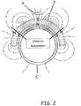
- the sensor 4 is arranged outside of the magnet 3 and in movement of the magnet 3 in each case directly opposite the magnetic poles of the respective magnet segment and is in the main flow direction of the magnetic field lines is on the FIG. 2 directed.
- the magnet 3 has exactly 3 magnet segments, each magnet segment having its own north and south pole N, S.
- the hand throttle 5 (handle) is shown schematically and in section with. Due to the rotational movement of the hand throttle grip 5, the magnet 3 shown is rotated with its at least 3 magnet segments with respect to the stationary sensor 4, so that the marked poles N, S of the respective magnet segment of the magnet 3 between the effective effective range (and possibly beyond) can move.
- magnet 3 with its exactly 3 magnet segments, this magnet 3 is annular, may be integrally formed as well as a disc-shaped magnet for detecting rotational movements or a longitudinally extending magnet for detecting translational movements, be part of the movable element be composed of several individual or separately produced magnetic segments. So z. B. for the realization of the annular magnet 3 according to FIG.
- individual ring segment magnets with one pole for example a ring segment magnet with a north pole lying on the outer circumference and two ring segment magnets with a south pole lying on the outer circumference (or vice versa) are produced and produced in a suitable manner (eg by gluing the like) a magnet extending along a direction of movement (reciprocation) which may also be suitably formed of a plurality of individual magnet segments having their own poles alternating in the direction of movement.
- the embodiment of the sensor arrangement 1 according to the FIGS. 1 and 2 are perpendicular to the direction of movement (when viewing the FIG. 2 a rotational movement about the longitudinal axis of the hand throttle grip 5) recorded magnetic components in one and the at least further direction (in particular the X and Z directions) of the magnetic field lines B (in particular Bx and Bz) for calculating the actual position of the hand throttle 5 based on its initial position) are used as absolute value. That means, that the position of the magnet 3 with respect to the sensor 4 can be mathematically deduced from the function of arctangent from Bx to Bz.
- the present invention thus realizes the advantages that few components are required for the sensor assembly 1 and this can be calibrated after their assembly.
- lengths translatorsichen movements up to 400 mm at a resolution of 0.1 mm can be realized.
- the cost-effective manufacturability and the long-term stability with simultaneous reduction of the external field influences and significant increase in the resolution should be mentioned as an advantage.
- This also applies analogously to a sensor arrangement 1 which is suitable for detecting rotational movements (in particular according to the exemplary embodiment) FIG. 1 and 2 ) is trained.
- the inventive sensor arrangement for the detection of rotational movements is applied, in which the angle of rotation is ⁇ 360 degrees.
Landscapes
- Physics & Mathematics (AREA)
- General Physics & Mathematics (AREA)
- Measurement Of Length, Angles, Or The Like Using Electric Or Magnetic Means (AREA)
- Transmission And Conversion Of Sensor Element Output (AREA)
Claims (3)
- Poignée d'accélération rotative (5) avec un agencement de capteur (1), configuré pour détecter le mouvement d'un arbre (2) de la poignée d'accélération rotative (5), présentant un aimant (3) déplaçable au moyen de l'arbre (2) ainsi qu'un capteur (4), conçu pour détecter le mouvement de l'aimant (3), dans laquelle la poignée d'accélération rotative (5) est déplaçable en rotation entre deux butées sur un angle de rotation inférieur à 360 degrés, caractérisée en ce que l'aimant (3) est divisé exactement en trois segments d'aimant, dans laquelle chaque segment d'aimant présente ses propres pôles Nord et Sud (N, S), en ce que le capteur (4) est disposé à l'extérieur de l'aimant (3) et lors du déplacement de l'aimant (3) chaque fois directement en face des pôles magnétiques du segment d'aimant respectif et se trouve dans la direction de flux principale des lignes de champ magnétique, dans laquelle un segment d'aimant est disposé avec le pôle Nord situé à la périphérie extérieure et un segment d'aimant est disposé respectivement à côté de celui-ci avec le pôle Sud situé à la périphérie extérieure ou un segment d'aimant est disposé avec le pôle Sud situé à la périphérie extérieure et un segment d'aimant est disposé respectivement à côté de celui-ci avec le pôle Nord situé à la périphérie extérieure, et dans laquelle l'angle de rotation de la poignée d'accélération rotative (5) est limité dans une plage comprise entre le milieu d'un premier segment d'aimant extérieur et le milieu de l'autre segment d'aimant extérieur, et dans laquelle les deux butées sont agencées à l'intérieur de cette plage.
- Poignée d'accélération rotative (5) selon la revendication 1, caractérisée en ce que l'aimant (3) présente une forme de construction ronde et est disposé et fixé sur l'arbre (2), dans laquelle le capteur (4) est en outre disposé à proximité immédiate de la périphérie extérieure de l'aimant (3).
- Poignée d'accélération rotative (5) selon l'une quelconque des revendications précédentes, caractérisée en ce que l'aimant (3) est réalisé en forme de disque ou d'anneau.
Applications Claiming Priority (2)
| Application Number | Priority Date | Filing Date | Title |
|---|---|---|---|
| DE102009056732 | 2009-12-04 | ||
| PCT/EP2010/007321 WO2011066969A1 (fr) | 2009-12-04 | 2010-12-02 | Système de mesure angulaire basé sur l'effet hall, notamment pour des poignées d'accélération rotatives |
Publications (2)
| Publication Number | Publication Date |
|---|---|
| EP2507592A1 EP2507592A1 (fr) | 2012-10-10 |
| EP2507592B1 true EP2507592B1 (fr) | 2019-01-30 |
Family
ID=43919772
Family Applications (1)
| Application Number | Title | Priority Date | Filing Date |
|---|---|---|---|
| EP10788252.4A Active EP2507592B1 (fr) | 2009-12-04 | 2010-12-02 | Poignée d'accélération rotative avec système de mesure angulaire |
Country Status (7)
| Country | Link |
|---|---|
| US (1) | US20120242331A1 (fr) |
| EP (1) | EP2507592B1 (fr) |
| JP (2) | JP5896912B2 (fr) |
| CA (1) | CA2782118C (fr) |
| DE (1) | DE102010053050A1 (fr) |
| ES (1) | ES2721875T3 (fr) |
| WO (1) | WO2011066969A1 (fr) |
Cited By (1)
| Publication number | Priority date | Publication date | Assignee | Title |
|---|---|---|---|---|
| WO2021116313A1 (fr) | 2019-12-10 | 2021-06-17 | Hirschmann Automotive Gmbh | Accélérateur électronique comprenant un bloc de commutation intégré |
Families Citing this family (7)
| Publication number | Priority date | Publication date | Assignee | Title |
|---|---|---|---|---|
| DE102011084191A1 (de) * | 2011-10-10 | 2013-04-11 | Robert Bosch Gmbh | Lenkanordnung |
| WO2014079470A1 (fr) * | 2012-11-23 | 2014-05-30 | Cameron International Corporation | Dispositif de mesure d'angle |
| JP6532060B2 (ja) * | 2015-11-05 | 2019-06-19 | アルプスアルパイン株式会社 | 回転角度検出装置 |
| FR3071605B1 (fr) * | 2017-09-25 | 2019-09-13 | Moving Magnet Technologies | Module de detection d’une poignee rotative d’un vehicule motorise |
| WO2019184983A1 (fr) * | 2018-03-28 | 2019-10-03 | 南京德朔实业有限公司 | Tondeuse à gazon à conducteur porté et son dispositif d'actionnement |
| US20230025376A1 (en) * | 2021-07-14 | 2023-01-26 | Fox Factory, Inc. | Timely component movement measuring system |
| IT202200002654A1 (it) | 2022-02-14 | 2023-08-14 | Domino S R L | Sistema per misurare la rotazione di una manopola del gas di un veicolo |
Citations (4)
| Publication number | Priority date | Publication date | Assignee | Title |
|---|---|---|---|---|
| US20040065165A1 (en) * | 2001-02-28 | 2004-04-08 | Mitsuru Sekiya | Accelerator operating device |
| EP1647435A1 (fr) * | 2004-10-14 | 2006-04-19 | Yamaha Hatsudoki Kabushiki Kaisha | Detecteur de position pour un véhicule à deux roues |
| JP2008020299A (ja) * | 2006-07-12 | 2008-01-31 | Aisin Seiki Co Ltd | 角度検出装置 |
| US20090201014A1 (en) * | 2006-07-19 | 2009-08-13 | Bitron S.P.A. | Twist-grip control device, in particular for motor vehicles |
Family Cites Families (18)
| Publication number | Priority date | Publication date | Assignee | Title |
|---|---|---|---|---|
| US5491632A (en) * | 1994-05-26 | 1996-02-13 | General Motors Corporation | Rotary encoder with neutral position |
| DE69827818T2 (de) * | 1997-09-08 | 2005-04-21 | Yaskawa Denki Kitakyushu Kk | Magnetische kodiereinrichtung |
| DE19748115C2 (de) * | 1997-10-31 | 2000-12-07 | Sican Gmbh | Vorrichtung zum elektromechanischen Schalten eines Gangwechselgetriebes |
| DE19910636A1 (de) * | 1999-03-10 | 2000-09-14 | Inst Mikrostrukturtechnologie | Längenmeßsystem, bestehend aus einem oder mehreren magnetischen Maßstäben |
| DE20017920U1 (de) * | 1999-12-14 | 2001-02-08 | Papst-Motoren GmbH & Co. KG, 78112 St Georgen | Anordnung zur Erfassung eines Magnetfelds |
| JP2002022403A (ja) * | 2000-07-13 | 2002-01-23 | Tokyo Keiso Co Ltd | 変位検出器および変位検出方法 |
| JP2002303535A (ja) * | 2001-04-03 | 2002-10-18 | Mikuni Corp | 磁気式位置センサ |
| US6576890B2 (en) * | 2001-06-05 | 2003-06-10 | Delphi Technologies, Inc. | Linear output non-contacting angular position sensor |
| WO2005108197A1 (fr) * | 2004-05-12 | 2005-11-17 | Mikuni Corporation | Dispositif d'exploitation d'accélérateur |
| JP4582298B2 (ja) * | 2004-07-08 | 2010-11-17 | Tdk株式会社 | 磁気式位置検出装置 |
| JP4401926B2 (ja) * | 2004-10-14 | 2010-01-20 | ヤマハ発動機株式会社 | 相対位置検出制御装置及び鞍乗型車両 |
| JP3848670B1 (ja) * | 2005-07-20 | 2006-11-22 | 株式会社トーメンエレクトロニクス | 回転角度検出装置 |
| FR2909170B1 (fr) * | 2006-11-28 | 2010-01-29 | Moving Magnet Tech Mmt | Capteur de position linaire ou rotatif a profil d'aimant variable preferentiellement de maniere quasi sinusoidal. |
| JP5131537B2 (ja) * | 2007-04-25 | 2013-01-30 | アイシン精機株式会社 | 角度検出装置 |
| DE102007023385A1 (de) * | 2007-05-18 | 2008-11-20 | Robert Bosch Gmbh | Vorrichtung zur berührungslosen Erfassung von Linear- oder Rotationsbewegungen |
| JP4941104B2 (ja) * | 2007-05-28 | 2012-05-30 | コニカミノルタオプト株式会社 | 位置検出装置、駆動装置及び光学機器 |
| JP2009150795A (ja) * | 2007-12-21 | 2009-07-09 | Hitachi Ltd | 非接触式回転角度検出センサ装置およびその出力補正方法 |
| WO2009099054A1 (fr) * | 2008-02-07 | 2009-08-13 | Hitachi Metals, Ltd. | Dispositif de détection d'angle de rotation, machine tournante et procédé de détection d'angle de rotation |
-
2010
- 2010-12-02 WO PCT/EP2010/007321 patent/WO2011066969A1/fr active Application Filing
- 2010-12-02 JP JP2012541358A patent/JP5896912B2/ja active Active
- 2010-12-02 US US13/508,504 patent/US20120242331A1/en not_active Abandoned
- 2010-12-02 ES ES10788252T patent/ES2721875T3/es active Active
- 2010-12-02 DE DE102010053050A patent/DE102010053050A1/de not_active Ceased
- 2010-12-02 CA CA2782118A patent/CA2782118C/fr active Active
- 2010-12-02 EP EP10788252.4A patent/EP2507592B1/fr active Active
-
2015
- 2015-11-06 JP JP2015218820A patent/JP2016020926A/ja active Pending
Patent Citations (4)
| Publication number | Priority date | Publication date | Assignee | Title |
|---|---|---|---|---|
| US20040065165A1 (en) * | 2001-02-28 | 2004-04-08 | Mitsuru Sekiya | Accelerator operating device |
| EP1647435A1 (fr) * | 2004-10-14 | 2006-04-19 | Yamaha Hatsudoki Kabushiki Kaisha | Detecteur de position pour un véhicule à deux roues |
| JP2008020299A (ja) * | 2006-07-12 | 2008-01-31 | Aisin Seiki Co Ltd | 角度検出装置 |
| US20090201014A1 (en) * | 2006-07-19 | 2009-08-13 | Bitron S.P.A. | Twist-grip control device, in particular for motor vehicles |
Cited By (3)
| Publication number | Priority date | Publication date | Assignee | Title |
|---|---|---|---|---|
| WO2021116313A1 (fr) | 2019-12-10 | 2021-06-17 | Hirschmann Automotive Gmbh | Accélérateur électronique comprenant un bloc de commutation intégré |
| DE102020132991A1 (de) | 2019-12-10 | 2021-08-05 | Hirschmann Automotive Gmbh | E-Gas mit integriertem Schalterblock |
| US20230026992A1 (en) * | 2019-12-10 | 2023-01-26 | Hirschmann Automotive Gmbh | Throttle with integrated switch block |
Also Published As
| Publication number | Publication date |
|---|---|
| JP5896912B2 (ja) | 2016-03-30 |
| JP2016020926A (ja) | 2016-02-04 |
| JP2013513092A (ja) | 2013-04-18 |
| WO2011066969A1 (fr) | 2011-06-09 |
| DE102010053050A1 (de) | 2011-06-22 |
| CA2782118C (fr) | 2019-08-06 |
| EP2507592A1 (fr) | 2012-10-10 |
| CA2782118A1 (fr) | 2011-06-09 |
| ES2721875T3 (es) | 2019-08-06 |
| US20120242331A1 (en) | 2012-09-27 |
Similar Documents
| Publication | Publication Date | Title |
|---|---|---|
| EP2507592B1 (fr) | Poignée d'accélération rotative avec système de mesure angulaire | |
| EP1445494B1 (fr) | Actionneur avec capteur de position | |
| EP2748053B1 (fr) | Capteur combiné visant le couple de braquage et l'angle de braquage | |
| DE102012206133A1 (de) | Anhängerkupplung | |
| DE102017222676A1 (de) | Wegsensor | |
| DE102006045827A1 (de) | Axialverschiebbares Bauteil insbesondere in einem Kraftfahrzeugmotor oder -getriebe | |
| DE102009047222A1 (de) | Sensoranordnung zum Ermitteln eines Drehmoments und zur Indexerkennung | |
| DE102013114825B4 (de) | Vorrichtung zur Messung eines Winkels einer Drehachse | |
| DE202015008430U1 (de) | Winkelmesseinrichtung und Elektromotor | |
| WO2021069014A1 (fr) | Appareil de détection de position d'angle de rotation d'un arbre rotatif et agencement de direction d'un véhicule | |
| DE102013205901A1 (de) | Schaltelement eines Fahrzeuggangräderwechselgetriebes | |
| EP2101157A2 (fr) | Capteur d'angle de rotation magnétique | |
| EP1600737A2 (fr) | Dispositif de mesure d'angle de rotation | |
| DE102006051720A1 (de) | Absolut messende Winkelsensoranordnung und Verfahren zur Winkelberechnung | |
| DE102019211482A1 (de) | Sensoranordnung | |
| EP3128294B1 (fr) | Capteur de determination de la position angulaire d'un moteur et moteur comprenant un capteur destine a determiner la position angulaire | |
| DE102012221327A1 (de) | Sensorvorrichtung zur Bestimmung mindestens einer Rotationseigenschaft eines rotierenden Elements | |
| EP3018452A1 (fr) | Systeme de mesure base sur un aimant destine a detecter un mouvement et/ou une position angulaire d'un composant | |
| DE102013214357A1 (de) | Messvorrichtung für ein manuelles Schaltgetriebe | |
| DE102008040360A1 (de) | Einrichtung zur Erfassung eines rotierenden Magnetfelds | |
| DE102019124973A1 (de) | Sensoranordnung zur Erfassung eines Lenkmomentes sowie einer absoluten Winkelposition und Sensorvorrichtung mit dieser Sensoranordnung | |
| DE102017205000A1 (de) | Messeinrichtung für einen Schwingungsdämpfer | |
| DE102013221688A1 (de) | Nutmutter und Anordnungen mit Nutmutter zur Messung physikalischer Größen | |
| DE10248695A1 (de) | Einrichtung zum Erfassen einer relativen Drehbewegung in einer Fahrzeug-Lenkeinrichtung | |
| DE102017202365A1 (de) | Sensoreinrichtung |
Legal Events
| Date | Code | Title | Description |
|---|---|---|---|
| PUAI | Public reference made under article 153(3) epc to a published international application that has entered the european phase |
Free format text: ORIGINAL CODE: 0009012 |
|
| 17P | Request for examination filed |
Effective date: 20120507 |
|
| AK | Designated contracting states |
Kind code of ref document: A1 Designated state(s): AL AT BE BG CH CY CZ DE DK EE ES FI FR GB GR HR HU IE IS IT LI LT LU LV MC MK MT NL NO PL PT RO RS SE SI SK SM TR |
|
| DAX | Request for extension of the european patent (deleted) | ||
| RIN1 | Information on inventor provided before grant (corrected) |
Inventor name: WALSER, BASTIEN Inventor name: KREUTER, MARKUS Inventor name: DENGLER, WERNER |
|
| STAA | Information on the status of an ep patent application or granted ep patent |
Free format text: STATUS: EXAMINATION IS IN PROGRESS |
|
| 17Q | First examination report despatched |
Effective date: 20161020 |
|
| GRAP | Despatch of communication of intention to grant a patent |
Free format text: ORIGINAL CODE: EPIDOSNIGR1 |
|
| STAA | Information on the status of an ep patent application or granted ep patent |
Free format text: STATUS: GRANT OF PATENT IS INTENDED |
|
| INTG | Intention to grant announced |
Effective date: 20180607 |
|
| GRAS | Grant fee paid |
Free format text: ORIGINAL CODE: EPIDOSNIGR3 |
|
| GRAA | (expected) grant |
Free format text: ORIGINAL CODE: 0009210 |
|
| STAA | Information on the status of an ep patent application or granted ep patent |
Free format text: STATUS: THE PATENT HAS BEEN GRANTED |
|
| AK | Designated contracting states |
Kind code of ref document: B1 Designated state(s): AL AT BE BG CH CY CZ DE DK EE ES FI FR GB GR HR HU IE IS IT LI LT LU LV MC MK MT NL NO PL PT RO RS SE SI SK SM TR |
|
| REG | Reference to a national code |
Ref country code: GB Ref legal event code: FG4D Free format text: NOT ENGLISH |
|
| REG | Reference to a national code |
Ref country code: CH Ref legal event code: EP |
|
| REG | Reference to a national code |
Ref country code: AT Ref legal event code: REF Ref document number: 1093649 Country of ref document: AT Kind code of ref document: T Effective date: 20190215 |
|
| REG | Reference to a national code |
Ref country code: RO Ref legal event code: EPE |
|
| REG | Reference to a national code |
Ref country code: IE Ref legal event code: FG4D Free format text: LANGUAGE OF EP DOCUMENT: GERMAN |
|
| REG | Reference to a national code |
Ref country code: DE Ref legal event code: R096 Ref document number: 502010015770 Country of ref document: DE |
|
| REG | Reference to a national code |
Ref country code: LT Ref legal event code: MG4D |
|
| REG | Reference to a national code |
Ref country code: NL Ref legal event code: MP Effective date: 20190130 |
|
| PG25 | Lapsed in a contracting state [announced via postgrant information from national office to epo] |
Ref country code: FI Free format text: LAPSE BECAUSE OF FAILURE TO SUBMIT A TRANSLATION OF THE DESCRIPTION OR TO PAY THE FEE WITHIN THE PRESCRIBED TIME-LIMIT Effective date: 20190130 Ref country code: NO Free format text: LAPSE BECAUSE OF FAILURE TO SUBMIT A TRANSLATION OF THE DESCRIPTION OR TO PAY THE FEE WITHIN THE PRESCRIBED TIME-LIMIT Effective date: 20190430 Ref country code: PT Free format text: LAPSE BECAUSE OF FAILURE TO SUBMIT A TRANSLATION OF THE DESCRIPTION OR TO PAY THE FEE WITHIN THE PRESCRIBED TIME-LIMIT Effective date: 20190530 Ref country code: SE Free format text: LAPSE BECAUSE OF FAILURE TO SUBMIT A TRANSLATION OF THE DESCRIPTION OR TO PAY THE FEE WITHIN THE PRESCRIBED TIME-LIMIT Effective date: 20190130 Ref country code: PL Free format text: LAPSE BECAUSE OF FAILURE TO SUBMIT A TRANSLATION OF THE DESCRIPTION OR TO PAY THE FEE WITHIN THE PRESCRIBED TIME-LIMIT Effective date: 20190130 Ref country code: NL Free format text: LAPSE BECAUSE OF FAILURE TO SUBMIT A TRANSLATION OF THE DESCRIPTION OR TO PAY THE FEE WITHIN THE PRESCRIBED TIME-LIMIT Effective date: 20190130 Ref country code: LT Free format text: LAPSE BECAUSE OF FAILURE TO SUBMIT A TRANSLATION OF THE DESCRIPTION OR TO PAY THE FEE WITHIN THE PRESCRIBED TIME-LIMIT Effective date: 20190130 |
|
| REG | Reference to a national code |
Ref country code: ES Ref legal event code: FG2A Ref document number: 2721875 Country of ref document: ES Kind code of ref document: T3 Effective date: 20190806 |
|
| PG25 | Lapsed in a contracting state [announced via postgrant information from national office to epo] |
Ref country code: LV Free format text: LAPSE BECAUSE OF FAILURE TO SUBMIT A TRANSLATION OF THE DESCRIPTION OR TO PAY THE FEE WITHIN THE PRESCRIBED TIME-LIMIT Effective date: 20190130 Ref country code: GR Free format text: LAPSE BECAUSE OF FAILURE TO SUBMIT A TRANSLATION OF THE DESCRIPTION OR TO PAY THE FEE WITHIN THE PRESCRIBED TIME-LIMIT Effective date: 20190501 Ref country code: HR Free format text: LAPSE BECAUSE OF FAILURE TO SUBMIT A TRANSLATION OF THE DESCRIPTION OR TO PAY THE FEE WITHIN THE PRESCRIBED TIME-LIMIT Effective date: 20190130 Ref country code: IS Free format text: LAPSE BECAUSE OF FAILURE TO SUBMIT A TRANSLATION OF THE DESCRIPTION OR TO PAY THE FEE WITHIN THE PRESCRIBED TIME-LIMIT Effective date: 20190530 Ref country code: BG Free format text: LAPSE BECAUSE OF FAILURE TO SUBMIT A TRANSLATION OF THE DESCRIPTION OR TO PAY THE FEE WITHIN THE PRESCRIBED TIME-LIMIT Effective date: 20190430 Ref country code: RS Free format text: LAPSE BECAUSE OF FAILURE TO SUBMIT A TRANSLATION OF THE DESCRIPTION OR TO PAY THE FEE WITHIN THE PRESCRIBED TIME-LIMIT Effective date: 20190130 |
|
| PG25 | Lapsed in a contracting state [announced via postgrant information from national office to epo] |
Ref country code: DK Free format text: LAPSE BECAUSE OF FAILURE TO SUBMIT A TRANSLATION OF THE DESCRIPTION OR TO PAY THE FEE WITHIN THE PRESCRIBED TIME-LIMIT Effective date: 20190130 Ref country code: EE Free format text: LAPSE BECAUSE OF FAILURE TO SUBMIT A TRANSLATION OF THE DESCRIPTION OR TO PAY THE FEE WITHIN THE PRESCRIBED TIME-LIMIT Effective date: 20190130 Ref country code: AL Free format text: LAPSE BECAUSE OF FAILURE TO SUBMIT A TRANSLATION OF THE DESCRIPTION OR TO PAY THE FEE WITHIN THE PRESCRIBED TIME-LIMIT Effective date: 20190130 Ref country code: SK Free format text: LAPSE BECAUSE OF FAILURE TO SUBMIT A TRANSLATION OF THE DESCRIPTION OR TO PAY THE FEE WITHIN THE PRESCRIBED TIME-LIMIT Effective date: 20190130 |
|
| REG | Reference to a national code |
Ref country code: DE Ref legal event code: R097 Ref document number: 502010015770 Country of ref document: DE |
|
| PG25 | Lapsed in a contracting state [announced via postgrant information from national office to epo] |
Ref country code: SM Free format text: LAPSE BECAUSE OF FAILURE TO SUBMIT A TRANSLATION OF THE DESCRIPTION OR TO PAY THE FEE WITHIN THE PRESCRIBED TIME-LIMIT Effective date: 20190130 |
|
| PLBE | No opposition filed within time limit |
Free format text: ORIGINAL CODE: 0009261 |
|
| STAA | Information on the status of an ep patent application or granted ep patent |
Free format text: STATUS: NO OPPOSITION FILED WITHIN TIME LIMIT |
|
| 26N | No opposition filed |
Effective date: 20191031 |
|
| PG25 | Lapsed in a contracting state [announced via postgrant information from national office to epo] |
Ref country code: SI Free format text: LAPSE BECAUSE OF FAILURE TO SUBMIT A TRANSLATION OF THE DESCRIPTION OR TO PAY THE FEE WITHIN THE PRESCRIBED TIME-LIMIT Effective date: 20190130 |
|
| PG25 | Lapsed in a contracting state [announced via postgrant information from national office to epo] |
Ref country code: TR Free format text: LAPSE BECAUSE OF FAILURE TO SUBMIT A TRANSLATION OF THE DESCRIPTION OR TO PAY THE FEE WITHIN THE PRESCRIBED TIME-LIMIT Effective date: 20190130 |
|
| REG | Reference to a national code |
Ref country code: CH Ref legal event code: PL |
|
| REG | Reference to a national code |
Ref country code: BE Ref legal event code: MM Effective date: 20191231 |
|
| PG25 | Lapsed in a contracting state [announced via postgrant information from national office to epo] |
Ref country code: MC Free format text: LAPSE BECAUSE OF FAILURE TO SUBMIT A TRANSLATION OF THE DESCRIPTION OR TO PAY THE FEE WITHIN THE PRESCRIBED TIME-LIMIT Effective date: 20190130 |
|
| PG25 | Lapsed in a contracting state [announced via postgrant information from national office to epo] |
Ref country code: IE Free format text: LAPSE BECAUSE OF NON-PAYMENT OF DUE FEES Effective date: 20191202 Ref country code: LU Free format text: LAPSE BECAUSE OF NON-PAYMENT OF DUE FEES Effective date: 20191202 |
|
| PG25 | Lapsed in a contracting state [announced via postgrant information from national office to epo] |
Ref country code: LI Free format text: LAPSE BECAUSE OF NON-PAYMENT OF DUE FEES Effective date: 20191231 Ref country code: CH Free format text: LAPSE BECAUSE OF NON-PAYMENT OF DUE FEES Effective date: 20191231 Ref country code: BE Free format text: LAPSE BECAUSE OF NON-PAYMENT OF DUE FEES Effective date: 20191231 |
|
| REG | Reference to a national code |
Ref country code: AT Ref legal event code: MM01 Ref document number: 1093649 Country of ref document: AT Kind code of ref document: T Effective date: 20191202 |
|
| PG25 | Lapsed in a contracting state [announced via postgrant information from national office to epo] |
Ref country code: CY Free format text: LAPSE BECAUSE OF FAILURE TO SUBMIT A TRANSLATION OF THE DESCRIPTION OR TO PAY THE FEE WITHIN THE PRESCRIBED TIME-LIMIT Effective date: 20190130 Ref country code: AT Free format text: LAPSE BECAUSE OF NON-PAYMENT OF DUE FEES Effective date: 20191202 |
|
| PG25 | Lapsed in a contracting state [announced via postgrant information from national office to epo] |
Ref country code: MT Free format text: LAPSE BECAUSE OF FAILURE TO SUBMIT A TRANSLATION OF THE DESCRIPTION OR TO PAY THE FEE WITHIN THE PRESCRIBED TIME-LIMIT Effective date: 20190130 Ref country code: HU Free format text: LAPSE BECAUSE OF FAILURE TO SUBMIT A TRANSLATION OF THE DESCRIPTION OR TO PAY THE FEE WITHIN THE PRESCRIBED TIME-LIMIT; INVALID AB INITIO Effective date: 20101202 |
|
| PG25 | Lapsed in a contracting state [announced via postgrant information from national office to epo] |
Ref country code: MK Free format text: LAPSE BECAUSE OF FAILURE TO SUBMIT A TRANSLATION OF THE DESCRIPTION OR TO PAY THE FEE WITHIN THE PRESCRIBED TIME-LIMIT Effective date: 20190130 |
|
| PGFP | Annual fee paid to national office [announced via postgrant information from national office to epo] |
Ref country code: GB Payment date: 20231220 Year of fee payment: 14 |
|
| PGFP | Annual fee paid to national office [announced via postgrant information from national office to epo] |
Ref country code: RO Payment date: 20231123 Year of fee payment: 14 Ref country code: IT Payment date: 20231228 Year of fee payment: 14 Ref country code: FR Payment date: 20231221 Year of fee payment: 14 Ref country code: DE Payment date: 20231214 Year of fee payment: 14 Ref country code: CZ Payment date: 20231127 Year of fee payment: 14 |
|
| PGFP | Annual fee paid to national office [announced via postgrant information from national office to epo] |
Ref country code: ES Payment date: 20240126 Year of fee payment: 14 |