EP2501492B1 - Dispositif et procédé ultrasoniques de traitement de surface - Google Patents
Dispositif et procédé ultrasoniques de traitement de surface Download PDFInfo
- Publication number
- EP2501492B1 EP2501492B1 EP10781984.9A EP10781984A EP2501492B1 EP 2501492 B1 EP2501492 B1 EP 2501492B1 EP 10781984 A EP10781984 A EP 10781984A EP 2501492 B1 EP2501492 B1 EP 2501492B1
- Authority
- EP
- European Patent Office
- Prior art keywords
- treatment composition
- mist
- mist generator
- treatment
- vibrating plate
- Prior art date
- Legal status (The legal status is an assumption and is not a legal conclusion. Google has not performed a legal analysis and makes no representation as to the accuracy of the status listed.)
- Active
Links
- 238000000034 method Methods 0.000 title claims description 15
- 238000004381 surface treatment Methods 0.000 title description 2
- 239000000203 mixture Substances 0.000 claims description 379
- 239000003595 mist Substances 0.000 claims description 357
- 239000012530 fluid Substances 0.000 claims description 63
- 230000008901 benefit Effects 0.000 claims description 46
- 229910052751 metal Inorganic materials 0.000 claims description 11
- 239000002184 metal Substances 0.000 claims description 11
- 239000000919 ceramic Substances 0.000 claims description 5
- 239000013566 allergen Substances 0.000 claims description 2
- 239000007787 solid Substances 0.000 claims description 2
- 238000004925 denaturation Methods 0.000 claims 1
- 230000036425 denaturation Effects 0.000 claims 1
- 239000007788 liquid Substances 0.000 description 124
- 239000002245 particle Substances 0.000 description 123
- 239000002585 base Substances 0.000 description 63
- 238000009826 distribution Methods 0.000 description 46
- 239000000463 material Substances 0.000 description 34
- -1 for example Chemical class 0.000 description 26
- 150000001875 compounds Chemical class 0.000 description 19
- 230000002093 peripheral effect Effects 0.000 description 17
- 239000003795 chemical substances by application Substances 0.000 description 16
- 239000004753 textile Substances 0.000 description 16
- 230000000712 assembly Effects 0.000 description 14
- 238000000429 assembly Methods 0.000 description 14
- 238000005406 washing Methods 0.000 description 14
- 125000000217 alkyl group Chemical group 0.000 description 12
- 230000004044 response Effects 0.000 description 12
- XLYOFNOQVPJJNP-UHFFFAOYSA-N water Substances O XLYOFNOQVPJJNP-UHFFFAOYSA-N 0.000 description 12
- 239000002253 acid Substances 0.000 description 11
- 239000000443 aerosol Substances 0.000 description 11
- 239000003205 fragrance Substances 0.000 description 11
- 230000000670 limiting effect Effects 0.000 description 11
- MHAJPDPJQMAIIY-UHFFFAOYSA-N Hydrogen peroxide Chemical compound OO MHAJPDPJQMAIIY-UHFFFAOYSA-N 0.000 description 10
- 239000000470 constituent Substances 0.000 description 10
- WQYVRQLZKVEZGA-UHFFFAOYSA-N hypochlorite Chemical group Cl[O-] WQYVRQLZKVEZGA-UHFFFAOYSA-N 0.000 description 10
- 150000003839 salts Chemical class 0.000 description 10
- 239000004599 antimicrobial Substances 0.000 description 9
- 230000002070 germicidal effect Effects 0.000 description 9
- 230000001965 increasing effect Effects 0.000 description 9
- 150000007524 organic acids Chemical class 0.000 description 9
- 239000000341 volatile oil Substances 0.000 description 9
- 239000003093 cationic surfactant Substances 0.000 description 8
- 239000003960 organic solvent Substances 0.000 description 8
- 238000005086 pumping Methods 0.000 description 8
- YGSDEFSMJLZEOE-UHFFFAOYSA-N salicylic acid Chemical compound OC(=O)C1=CC=CC=C1O YGSDEFSMJLZEOE-UHFFFAOYSA-N 0.000 description 8
- 150000007513 acids Chemical class 0.000 description 7
- 230000001939 inductive effect Effects 0.000 description 7
- 239000006199 nebulizer Substances 0.000 description 7
- 230000010355 oscillation Effects 0.000 description 7
- 239000002699 waste material Substances 0.000 description 7
- QTBSBXVTEAMEQO-UHFFFAOYSA-N Acetic acid Chemical compound CC(O)=O QTBSBXVTEAMEQO-UHFFFAOYSA-N 0.000 description 6
- LYCAIKOWRPUZTN-UHFFFAOYSA-N Ethylene glycol Chemical compound OCCO LYCAIKOWRPUZTN-UHFFFAOYSA-N 0.000 description 6
- DNIAPMSPPWPWGF-UHFFFAOYSA-N Propylene glycol Chemical compound CC(O)CO DNIAPMSPPWPWGF-UHFFFAOYSA-N 0.000 description 6
- 229910052783 alkali metal Inorganic materials 0.000 description 6
- 230000000845 anti-microbial effect Effects 0.000 description 6
- 238000000222 aromatherapy Methods 0.000 description 6
- KRKNYBCHXYNGOX-UHFFFAOYSA-N citric acid Chemical compound OC(=O)CC(O)(C(O)=O)CC(O)=O KRKNYBCHXYNGOX-UHFFFAOYSA-N 0.000 description 6
- 238000004140 cleaning Methods 0.000 description 6
- 238000000151 deposition Methods 0.000 description 6
- 238000001035 drying Methods 0.000 description 6
- 239000013536 elastomeric material Substances 0.000 description 6
- 150000002148 esters Chemical class 0.000 description 6
- 239000002736 nonionic surfactant Substances 0.000 description 6
- 235000005985 organic acids Nutrition 0.000 description 6
- 239000004094 surface-active agent Substances 0.000 description 6
- WSFSSNUMVMOOMR-UHFFFAOYSA-N Formaldehyde Chemical compound O=C WSFSSNUMVMOOMR-UHFFFAOYSA-N 0.000 description 5
- 125000000129 anionic group Chemical group 0.000 description 5
- 239000003945 anionic surfactant Substances 0.000 description 5
- 239000002979 fabric softener Substances 0.000 description 5
- 230000005484 gravity Effects 0.000 description 5
- 230000003472 neutralizing effect Effects 0.000 description 5
- 239000007800 oxidant agent Substances 0.000 description 5
- 150000004965 peroxy acids Chemical class 0.000 description 5
- 238000011012 sanitization Methods 0.000 description 5
- LFQSCWFLJHTTHZ-UHFFFAOYSA-N Ethanol Chemical compound CCO LFQSCWFLJHTTHZ-UHFFFAOYSA-N 0.000 description 4
- AEMRFAOFKBGASW-UHFFFAOYSA-N Glycolic acid Chemical compound OCC(O)=O AEMRFAOFKBGASW-UHFFFAOYSA-N 0.000 description 4
- ZLMJMSJWJFRBEC-UHFFFAOYSA-N Potassium Chemical compound [K] ZLMJMSJWJFRBEC-UHFFFAOYSA-N 0.000 description 4
- 150000001340 alkali metals Chemical group 0.000 description 4
- 125000003118 aryl group Chemical group 0.000 description 4
- 125000004432 carbon atom Chemical group C* 0.000 description 4
- 125000002091 cationic group Chemical group 0.000 description 4
- 238000004891 communication Methods 0.000 description 4
- 238000010276 construction Methods 0.000 description 4
- 230000008021 deposition Effects 0.000 description 4
- 238000004851 dishwashing Methods 0.000 description 4
- 230000006870 function Effects 0.000 description 4
- 239000007789 gas Substances 0.000 description 4
- JGJLWPGRMCADHB-UHFFFAOYSA-N hypobromite Chemical compound Br[O-] JGJLWPGRMCADHB-UHFFFAOYSA-N 0.000 description 4
- JVTAAEKCZFNVCJ-UHFFFAOYSA-N lactic acid Chemical compound CC(O)C(O)=O JVTAAEKCZFNVCJ-UHFFFAOYSA-N 0.000 description 4
- 230000000873 masking effect Effects 0.000 description 4
- 230000003534 oscillatory effect Effects 0.000 description 4
- FJKROLUGYXJWQN-UHFFFAOYSA-N papa-hydroxy-benzoic acid Natural products OC(=O)C1=CC=C(O)C=C1 FJKROLUGYXJWQN-UHFFFAOYSA-N 0.000 description 4
- 239000002304 perfume Substances 0.000 description 4
- 229910052700 potassium Inorganic materials 0.000 description 4
- 239000011591 potassium Substances 0.000 description 4
- 230000008569 process Effects 0.000 description 4
- 125000001453 quaternary ammonium group Chemical group 0.000 description 4
- 229960004889 salicylic acid Drugs 0.000 description 4
- 230000003068 static effect Effects 0.000 description 4
- ZIBGPFATKBEMQZ-UHFFFAOYSA-N triethylene glycol Chemical compound OCCOCCOCCO ZIBGPFATKBEMQZ-UHFFFAOYSA-N 0.000 description 4
- DGAQECJNVWCQMB-PUAWFVPOSA-M Ilexoside XXIX Chemical compound C[C@@H]1CC[C@@]2(CC[C@@]3(C(=CC[C@H]4[C@]3(CC[C@@H]5[C@@]4(CC[C@@H](C5(C)C)OS(=O)(=O)[O-])C)C)[C@@H]2[C@]1(C)O)C)C(=O)O[C@H]6[C@@H]([C@H]([C@@H]([C@H](O6)CO)O)O)O.[Na+] DGAQECJNVWCQMB-PUAWFVPOSA-M 0.000 description 3
- 229910019142 PO4 Inorganic materials 0.000 description 3
- OFOBLEOULBTSOW-UHFFFAOYSA-N Propanedioic acid Natural products OC(=O)CC(O)=O OFOBLEOULBTSOW-UHFFFAOYSA-N 0.000 description 3
- 230000009471 action Effects 0.000 description 3
- 230000004913 activation Effects 0.000 description 3
- 125000003342 alkenyl group Chemical group 0.000 description 3
- 150000001408 amides Chemical class 0.000 description 3
- 239000002280 amphoteric surfactant Substances 0.000 description 3
- 230000015572 biosynthetic process Effects 0.000 description 3
- 239000007844 bleaching agent Substances 0.000 description 3
- 150000004649 carbonic acid derivatives Chemical class 0.000 description 3
- 239000011248 coating agent Substances 0.000 description 3
- 238000000576 coating method Methods 0.000 description 3
- 150000002170 ethers Chemical class 0.000 description 3
- 229940052303 ethers for general anesthesia Drugs 0.000 description 3
- 239000004744 fabric Substances 0.000 description 3
- 239000000835 fiber Substances 0.000 description 3
- 230000009969 flowable effect Effects 0.000 description 3
- 230000002209 hydrophobic effect Effects 0.000 description 3
- 239000003752 hydrotrope Substances 0.000 description 3
- 238000002347 injection Methods 0.000 description 3
- 239000007924 injection Substances 0.000 description 3
- 229910052500 inorganic mineral Inorganic materials 0.000 description 3
- 230000005499 meniscus Effects 0.000 description 3
- 239000011707 mineral Chemical class 0.000 description 3
- 150000007522 mineralic acids Chemical class 0.000 description 3
- 239000003921 oil Substances 0.000 description 3
- 235000019198 oils Nutrition 0.000 description 3
- 239000003002 pH adjusting agent Substances 0.000 description 3
- 230000037361 pathway Effects 0.000 description 3
- 235000021317 phosphate Nutrition 0.000 description 3
- 239000000047 product Substances 0.000 description 3
- 239000003380 propellant Substances 0.000 description 3
- 150000003856 quaternary ammonium compounds Chemical class 0.000 description 3
- 150000003254 radicals Chemical class 0.000 description 3
- 238000007789 sealing Methods 0.000 description 3
- 239000011734 sodium Substances 0.000 description 3
- 229910052708 sodium Inorganic materials 0.000 description 3
- 241000894007 species Species 0.000 description 3
- 239000007921 spray Substances 0.000 description 3
- 239000000126 substance Substances 0.000 description 3
- 150000003467 sulfuric acid derivatives Chemical class 0.000 description 3
- 229920001059 synthetic polymer Polymers 0.000 description 3
- 238000012546 transfer Methods 0.000 description 3
- BJEPYKJPYRNKOW-REOHCLBHSA-N (S)-malic acid Chemical compound OC(=O)[C@@H](O)CC(O)=O BJEPYKJPYRNKOW-REOHCLBHSA-N 0.000 description 2
- YRIZYWQGELRKNT-UHFFFAOYSA-N 1,3,5-trichloro-1,3,5-triazinane-2,4,6-trione Chemical compound ClN1C(=O)N(Cl)C(=O)N(Cl)C1=O YRIZYWQGELRKNT-UHFFFAOYSA-N 0.000 description 2
- IYOLBFFHPZOQGW-UHFFFAOYSA-N 2,4-dichloro-3,5-dimethylphenol Chemical compound CC1=CC(O)=C(Cl)C(C)=C1Cl IYOLBFFHPZOQGW-UHFFFAOYSA-N 0.000 description 2
- CHZLVSBMXZSPNN-UHFFFAOYSA-N 2,4-dimethylbenzenesulfonic acid Chemical class CC1=CC=C(S(O)(=O)=O)C(C)=C1 CHZLVSBMXZSPNN-UHFFFAOYSA-N 0.000 description 2
- SVTBMSDMJJWYQN-UHFFFAOYSA-N 2-methylpentane-2,4-diol Chemical compound CC(O)CC(C)(C)O SVTBMSDMJJWYQN-UHFFFAOYSA-N 0.000 description 2
- WRMNZCZEMHIOCP-UHFFFAOYSA-N 2-phenylethanol Chemical compound OCCC1=CC=CC=C1 WRMNZCZEMHIOCP-UHFFFAOYSA-N 0.000 description 2
- OSDLLIBGSJNGJE-UHFFFAOYSA-N 4-chloro-3,5-dimethylphenol Chemical compound CC1=CC(O)=CC(C)=C1Cl OSDLLIBGSJNGJE-UHFFFAOYSA-N 0.000 description 2
- WXNZTHHGJRFXKQ-UHFFFAOYSA-N 4-chlorophenol Chemical compound OC1=CC=C(Cl)C=C1 WXNZTHHGJRFXKQ-UHFFFAOYSA-N 0.000 description 2
- QGZKDVFQNNGYKY-UHFFFAOYSA-O Ammonium Chemical compound [NH4+] QGZKDVFQNNGYKY-UHFFFAOYSA-O 0.000 description 2
- 229940123208 Biguanide Drugs 0.000 description 2
- GHXZTYHSJHQHIJ-UHFFFAOYSA-N Chlorhexidine Chemical compound C=1C=C(Cl)C=CC=1NC(N)=NC(N)=NCCCCCCN=C(N)N=C(N)NC1=CC=C(Cl)C=C1 GHXZTYHSJHQHIJ-UHFFFAOYSA-N 0.000 description 2
- RTZKZFJDLAIYFH-UHFFFAOYSA-N Diethyl ether Chemical compound CCOCC RTZKZFJDLAIYFH-UHFFFAOYSA-N 0.000 description 2
- IAYPIBMASNFSPL-UHFFFAOYSA-N Ethylene oxide Chemical compound C1CO1 IAYPIBMASNFSPL-UHFFFAOYSA-N 0.000 description 2
- FMRHJJZUHUTGKE-UHFFFAOYSA-N Ethylhexyl salicylate Chemical compound CCCCC(CC)COC(=O)C1=CC=CC=C1O FMRHJJZUHUTGKE-UHFFFAOYSA-N 0.000 description 2
- 241000238631 Hexapoda Species 0.000 description 2
- VEXZGXHMUGYJMC-UHFFFAOYSA-N Hydrochloric acid Chemical compound Cl VEXZGXHMUGYJMC-UHFFFAOYSA-N 0.000 description 2
- KFZMGEQAYNKOFK-UHFFFAOYSA-N Isopropanol Chemical compound CC(C)O KFZMGEQAYNKOFK-UHFFFAOYSA-N 0.000 description 2
- 235000019502 Orange oil Nutrition 0.000 description 2
- KFSLWBXXFJQRDL-UHFFFAOYSA-N Peracetic acid Chemical compound CC(=O)OO KFSLWBXXFJQRDL-UHFFFAOYSA-N 0.000 description 2
- NBIIXXVUZAFLBC-UHFFFAOYSA-N Phosphoric acid Chemical compound OP(O)(O)=O NBIIXXVUZAFLBC-UHFFFAOYSA-N 0.000 description 2
- 239000002202 Polyethylene glycol Substances 0.000 description 2
- 229920002413 Polyhexanide Polymers 0.000 description 2
- QAOWNCQODCNURD-UHFFFAOYSA-N Sulfuric acid Chemical compound OS(O)(=O)=O QAOWNCQODCNURD-UHFFFAOYSA-N 0.000 description 2
- 238000010521 absorption reaction Methods 0.000 description 2
- 235000011054 acetic acid Nutrition 0.000 description 2
- WNLRTRBMVRJNCN-UHFFFAOYSA-N adipic acid Chemical compound OC(=O)CCCCC(O)=O WNLRTRBMVRJNCN-UHFFFAOYSA-N 0.000 description 2
- 150000001298 alcohols Chemical class 0.000 description 2
- 125000001931 aliphatic group Chemical group 0.000 description 2
- 125000002877 alkyl aryl group Chemical group 0.000 description 2
- BJEPYKJPYRNKOW-UHFFFAOYSA-N alpha-hydroxysuccinic acid Natural products OC(=O)C(O)CC(O)=O BJEPYKJPYRNKOW-UHFFFAOYSA-N 0.000 description 2
- 150000001412 amines Chemical class 0.000 description 2
- 230000009118 appropriate response Effects 0.000 description 2
- 238000000889 atomisation Methods 0.000 description 2
- 230000009286 beneficial effect Effects 0.000 description 2
- SRSXLGNVWSONIS-UHFFFAOYSA-N benzenesulfonic acid Chemical class OS(=O)(=O)C1=CC=CC=C1 SRSXLGNVWSONIS-UHFFFAOYSA-N 0.000 description 2
- LLEMOWNGBBNAJR-UHFFFAOYSA-N biphenyl-2-ol Chemical compound OC1=CC=CC=C1C1=CC=CC=C1 LLEMOWNGBBNAJR-UHFFFAOYSA-N 0.000 description 2
- 238000004061 bleaching Methods 0.000 description 2
- 150000001642 boronic acid derivatives Chemical class 0.000 description 2
- 239000000872 buffer Substances 0.000 description 2
- 230000015556 catabolic process Effects 0.000 description 2
- 229960003260 chlorhexidine Drugs 0.000 description 2
- 235000015165 citric acid Nutrition 0.000 description 2
- 230000006835 compression Effects 0.000 description 2
- 238000007906 compression Methods 0.000 description 2
- 239000004020 conductor Substances 0.000 description 2
- 238000006731 degradation reaction Methods 0.000 description 2
- 230000000249 desinfective effect Effects 0.000 description 2
- CEJLBZWIKQJOAT-UHFFFAOYSA-N dichloroisocyanuric acid Chemical compound ClN1C(=O)NC(=O)N(Cl)C1=O CEJLBZWIKQJOAT-UHFFFAOYSA-N 0.000 description 2
- 238000010790 dilution Methods 0.000 description 2
- 239000012895 dilution Substances 0.000 description 2
- 229910001882 dioxygen Inorganic materials 0.000 description 2
- 230000000694 effects Effects 0.000 description 2
- 229920001971 elastomer Polymers 0.000 description 2
- 230000008029 eradication Effects 0.000 description 2
- 150000002191 fatty alcohols Chemical class 0.000 description 2
- KWIUHFFTVRNATP-UHFFFAOYSA-N glycine betaine Chemical compound C[N+](C)(C)CC([O-])=O KWIUHFFTVRNATP-UHFFFAOYSA-N 0.000 description 2
- 229910052736 halogen Inorganic materials 0.000 description 2
- 238000010438 heat treatment Methods 0.000 description 2
- 229930195733 hydrocarbon Natural products 0.000 description 2
- 150000002430 hydrocarbons Chemical class 0.000 description 2
- 125000001183 hydrocarbyl group Chemical group 0.000 description 2
- 150000004679 hydroxides Chemical class 0.000 description 2
- 238000011065 in-situ storage Methods 0.000 description 2
- 238000009434 installation Methods 0.000 description 2
- 239000004310 lactic acid Substances 0.000 description 2
- 235000014655 lactic acid Nutrition 0.000 description 2
- 239000001630 malic acid Substances 0.000 description 2
- 235000011090 malic acid Nutrition 0.000 description 2
- 150000004972 metal peroxides Chemical class 0.000 description 2
- BDAGIHXWWSANSR-UHFFFAOYSA-N methanoic acid Natural products OC=O BDAGIHXWWSANSR-UHFFFAOYSA-N 0.000 description 2
- 150000002772 monosaccharides Chemical class 0.000 description 2
- PSZYNBSKGUBXEH-UHFFFAOYSA-N naphthalene-1-sulfonic acid Chemical class C1=CC=C2C(S(=O)(=O)O)=CC=CC2=C1 PSZYNBSKGUBXEH-UHFFFAOYSA-N 0.000 description 2
- 238000006386 neutralization reaction Methods 0.000 description 2
- 239000010502 orange oil Substances 0.000 description 2
- 239000006174 pH buffer Substances 0.000 description 2
- 230000035515 penetration Effects 0.000 description 2
- 230000000737 periodic effect Effects 0.000 description 2
- 229920001223 polyethylene glycol Polymers 0.000 description 2
- 229920000642 polymer Polymers 0.000 description 2
- 229920001296 polysiloxane Polymers 0.000 description 2
- 230000002829 reductive effect Effects 0.000 description 2
- GHMLBKRAJCXXBS-UHFFFAOYSA-N resorcinol Chemical compound OC1=CC=CC(O)=C1 GHMLBKRAJCXXBS-UHFFFAOYSA-N 0.000 description 2
- 230000000717 retained effect Effects 0.000 description 2
- 150000004760 silicates Chemical class 0.000 description 2
- GEHJYWRUCIMESM-UHFFFAOYSA-L sodium sulfite Chemical compound [Na+].[Na+].[O-]S([O-])=O GEHJYWRUCIMESM-UHFFFAOYSA-L 0.000 description 2
- 238000001179 sorption measurement Methods 0.000 description 2
- 238000010186 staining Methods 0.000 description 2
- 125000001424 substituent group Chemical group 0.000 description 2
- 238000009736 wetting Methods 0.000 description 2
- LDVVMCZRFWMZSG-OLQVQODUSA-N (3ar,7as)-2-(trichloromethylsulfanyl)-3a,4,7,7a-tetrahydroisoindole-1,3-dione Chemical compound C1C=CC[C@H]2C(=O)N(SC(Cl)(Cl)Cl)C(=O)[C@H]21 LDVVMCZRFWMZSG-OLQVQODUSA-N 0.000 description 1
- RBNPOMFGQQGHHO-UHFFFAOYSA-N -2,3-Dihydroxypropanoic acid Natural products OCC(O)C(O)=O RBNPOMFGQQGHHO-UHFFFAOYSA-N 0.000 description 1
- LEEANUDEDHYDTG-UHFFFAOYSA-N 1,2-dimethoxypropane Chemical compound COCC(C)OC LEEANUDEDHYDTG-UHFFFAOYSA-N 0.000 description 1
- HHBCEKAWSILOOP-UHFFFAOYSA-N 1,3-dibromo-1,3,5-triazinane-2,4,6-trione Chemical compound BrN1C(=O)NC(=O)N(Br)C1=O HHBCEKAWSILOOP-UHFFFAOYSA-N 0.000 description 1
- KEQGZUUPPQEDPF-UHFFFAOYSA-N 1,3-dichloro-5,5-dimethylimidazolidine-2,4-dione Chemical compound CC1(C)N(Cl)C(=O)N(Cl)C1=O KEQGZUUPPQEDPF-UHFFFAOYSA-N 0.000 description 1
- NWGAAWUUGRXXSC-UHFFFAOYSA-N 1-(2-hydroxypropoxy)propan-2-yl 2-hydroxybenzoate Chemical compound CC(O)COCC(C)OC(=O)C1=CC=CC=C1O NWGAAWUUGRXXSC-UHFFFAOYSA-N 0.000 description 1
- VAZJLPXFVQHDFB-UHFFFAOYSA-N 1-(diaminomethylidene)-2-hexylguanidine Polymers CCCCCCN=C(N)N=C(N)N VAZJLPXFVQHDFB-UHFFFAOYSA-N 0.000 description 1
- RWNUSVWFHDHRCJ-UHFFFAOYSA-N 1-butoxypropan-2-ol Chemical compound CCCCOCC(C)O RWNUSVWFHDHRCJ-UHFFFAOYSA-N 0.000 description 1
- UWMJRBYGKZOPCC-UHFFFAOYSA-N 1-chloro-5,5-dimethylimidazolidine-2,4-dione Chemical compound CC1(C)N(Cl)C(=O)NC1=O UWMJRBYGKZOPCC-UHFFFAOYSA-N 0.000 description 1
- RRQYJINTUHWNHW-UHFFFAOYSA-N 1-ethoxy-2-(2-ethoxyethoxy)ethane Chemical compound CCOCCOCCOCC RRQYJINTUHWNHW-UHFFFAOYSA-N 0.000 description 1
- JOLQKTGDSGKSKJ-UHFFFAOYSA-N 1-ethoxypropan-2-ol Chemical compound CCOCC(C)O JOLQKTGDSGKSKJ-UHFFFAOYSA-N 0.000 description 1
- ARXJGSRGQADJSQ-UHFFFAOYSA-N 1-methoxypropan-2-ol Chemical compound COCC(C)O ARXJGSRGQADJSQ-UHFFFAOYSA-N 0.000 description 1
- ZZXDRXVIRVJQBT-UHFFFAOYSA-N 2,3-dimethylbenzenesulfonic acid Chemical class CC1=CC=CC(S(O)(=O)=O)=C1C ZZXDRXVIRVJQBT-UHFFFAOYSA-N 0.000 description 1
- HTYFFCPFVMJTKM-UHFFFAOYSA-N 2-(4-chlorophenyl)-1-(diaminomethylidene)guanidine Chemical compound NC(N)=NC(N)=NC1=CC=C(Cl)C=C1 HTYFFCPFVMJTKM-UHFFFAOYSA-N 0.000 description 1
- LBLYYCQCTBFVLH-UHFFFAOYSA-N 2-Methylbenzenesulfonic acid Chemical class CC1=CC=CC=C1S(O)(=O)=O LBLYYCQCTBFVLH-UHFFFAOYSA-N 0.000 description 1
- NCKMMSIFQUPKCK-UHFFFAOYSA-N 2-benzyl-4-chlorophenol Chemical compound OC1=CC=C(Cl)C=C1CC1=CC=CC=C1 NCKMMSIFQUPKCK-UHFFFAOYSA-N 0.000 description 1
- POAOYUHQDCAZBD-UHFFFAOYSA-N 2-butoxyethanol Chemical compound CCCCOCCO POAOYUHQDCAZBD-UHFFFAOYSA-N 0.000 description 1
- SQERDRRMCKKWIL-UHFFFAOYSA-N 2-hydroperoxy-2-oxoacetic acid Chemical compound OOC(=O)C(O)=O SQERDRRMCKKWIL-UHFFFAOYSA-N 0.000 description 1
- FEWFXBUNENSNBQ-UHFFFAOYSA-N 2-hydroxyacrylic acid Chemical compound OC(=C)C(O)=O FEWFXBUNENSNBQ-UHFFFAOYSA-N 0.000 description 1
- AFENDNXGAFYKQO-UHFFFAOYSA-N 2-hydroxybutyric acid Chemical compound CCC(O)C(O)=O AFENDNXGAFYKQO-UHFFFAOYSA-N 0.000 description 1
- 229940100555 2-methyl-4-isothiazolin-3-one Drugs 0.000 description 1
- JBVOQKNLGSOPNZ-UHFFFAOYSA-N 2-propan-2-ylbenzenesulfonic acid Chemical class CC(C)C1=CC=CC=C1S(O)(=O)=O JBVOQKNLGSOPNZ-UHFFFAOYSA-N 0.000 description 1
- QCAHUFWKIQLBNB-UHFFFAOYSA-N 3-(3-methoxypropoxy)propan-1-ol Chemical compound COCCCOCCCO QCAHUFWKIQLBNB-UHFFFAOYSA-N 0.000 description 1
- RMTFNDVZYPHUEF-XZBKPIIZSA-N 3-O-methyl-D-glucose Chemical compound O=C[C@H](O)[C@@H](OC)[C@H](O)[C@H](O)CO RMTFNDVZYPHUEF-XZBKPIIZSA-N 0.000 description 1
- AVWFGNBVNWCEIM-UHFFFAOYSA-N 3-[ethyl(methoxy)amino]propan-1-ol Chemical compound CCN(OC)CCCO AVWFGNBVNWCEIM-UHFFFAOYSA-N 0.000 description 1
- WMKZAKWDJDKLIW-UHFFFAOYSA-N 3-iodoprop-1-enyl n-butylcarbamate Chemical compound CCCCNC(=O)OC=CCI WMKZAKWDJDKLIW-UHFFFAOYSA-N 0.000 description 1
- JDQDSEVNMTYMOC-UHFFFAOYSA-N 3-methylbenzenesulfonic acid Chemical class CC1=CC=CC(S(O)(=O)=O)=C1 JDQDSEVNMTYMOC-UHFFFAOYSA-N 0.000 description 1
- LDMRLRNXHLPZJN-UHFFFAOYSA-N 3-propoxypropan-1-ol Chemical compound CCCOCCCO LDMRLRNXHLPZJN-UHFFFAOYSA-N 0.000 description 1
- TZZGHGKTHXIOMN-UHFFFAOYSA-N 3-trimethoxysilyl-n-(3-trimethoxysilylpropyl)propan-1-amine Chemical compound CO[Si](OC)(OC)CCCNCCC[Si](OC)(OC)OC TZZGHGKTHXIOMN-UHFFFAOYSA-N 0.000 description 1
- OSWFIVFLDKOXQC-UHFFFAOYSA-N 4-(3-methoxyphenyl)aniline Chemical compound COC1=CC=CC(C=2C=CC(N)=CC=2)=C1 OSWFIVFLDKOXQC-UHFFFAOYSA-N 0.000 description 1
- IJALWSVNUBBQRA-UHFFFAOYSA-N 4-Isopropyl-3-methylphenol Chemical compound CC(C)C1=CC=C(O)C=C1C IJALWSVNUBBQRA-UHFFFAOYSA-N 0.000 description 1
- GKCCTCWZNGMJKG-UHFFFAOYSA-N 4-chloro-2-[(5-chloro-2-hydroxyphenyl)methylsulfanylmethyl]phenol Chemical compound OC1=CC=C(Cl)C=C1CSCC1=CC(Cl)=CC=C1O GKCCTCWZNGMJKG-UHFFFAOYSA-N 0.000 description 1
- RHPUJHQBPORFGV-UHFFFAOYSA-N 4-chloro-2-methylphenol Chemical compound CC1=CC(Cl)=CC=C1O RHPUJHQBPORFGV-UHFFFAOYSA-N 0.000 description 1
- KFZXVMNBUMVKLN-UHFFFAOYSA-N 4-chloro-5-methyl-2-propan-2-ylphenol Chemical compound CC(C)C1=CC(Cl)=C(C)C=C1O KFZXVMNBUMVKLN-UHFFFAOYSA-N 0.000 description 1
- HJANTALXTYZKRB-UHFFFAOYSA-N 5,5-bis(hydroxymethyl)-1,3-dimethylimidazolidine-2,4-dione Chemical compound CN1C(=O)N(C)C(CO)(CO)C1=O HJANTALXTYZKRB-UHFFFAOYSA-N 0.000 description 1
- 229940046305 5-bromo-5-nitro-1,3-dioxane Drugs 0.000 description 1
- 229940100484 5-chloro-2-methyl-4-isothiazolin-3-one Drugs 0.000 description 1
- KCAZSAYYICOMMG-UHFFFAOYSA-N 6-hydroperoxy-6-oxohexanoic acid Chemical compound OOC(=O)CCCCC(O)=O KCAZSAYYICOMMG-UHFFFAOYSA-N 0.000 description 1
- RZVAJINKPMORJF-UHFFFAOYSA-N Acetaminophen Chemical compound CC(=O)NC1=CC=C(O)C=C1 RZVAJINKPMORJF-UHFFFAOYSA-N 0.000 description 1
- CPELXLSAUQHCOX-UHFFFAOYSA-M Bromide Chemical compound [Br-] CPELXLSAUQHCOX-UHFFFAOYSA-M 0.000 description 1
- LVDKZNITIUWNER-UHFFFAOYSA-N Bronopol Chemical compound OCC(Br)(CO)[N+]([O-])=O LVDKZNITIUWNER-UHFFFAOYSA-N 0.000 description 1
- ZKQDCIXGCQPQNV-UHFFFAOYSA-N Calcium hypochlorite Chemical compound [Ca+2].Cl[O-].Cl[O-] ZKQDCIXGCQPQNV-UHFFFAOYSA-N 0.000 description 1
- 239000004343 Calcium peroxide Substances 0.000 description 1
- 239000005745 Captan Substances 0.000 description 1
- 239000004215 Carbon black (E152) Substances 0.000 description 1
- QDHHCQZDFGDHMP-UHFFFAOYSA-N Chloramine Chemical compound ClN QDHHCQZDFGDHMP-UHFFFAOYSA-N 0.000 description 1
- VEXZGXHMUGYJMC-UHFFFAOYSA-M Chloride anion Chemical compound [Cl-] VEXZGXHMUGYJMC-UHFFFAOYSA-M 0.000 description 1
- 241001672694 Citrus reticulata Species 0.000 description 1
- OCUCCJIRFHNWBP-IYEMJOQQSA-L Copper gluconate Chemical class [Cu+2].OC[C@@H](O)[C@@H](O)[C@H](O)[C@@H](O)C([O-])=O.OC[C@@H](O)[C@@H](O)[C@H](O)[C@@H](O)C([O-])=O OCUCCJIRFHNWBP-IYEMJOQQSA-L 0.000 description 1
- FBPFZTCFMRRESA-FSIIMWSLSA-N D-Glucitol Natural products OC[C@H](O)[C@H](O)[C@@H](O)[C@H](O)CO FBPFZTCFMRRESA-FSIIMWSLSA-N 0.000 description 1
- FBPFZTCFMRRESA-JGWLITMVSA-N D-glucitol Chemical compound OC[C@H](O)[C@@H](O)[C@H](O)[C@H](O)CO FBPFZTCFMRRESA-JGWLITMVSA-N 0.000 description 1
- RBNPOMFGQQGHHO-UWTATZPHSA-N D-glyceric acid Chemical compound OC[C@@H](O)C(O)=O RBNPOMFGQQGHHO-UWTATZPHSA-N 0.000 description 1
- FEWJPZIEWOKRBE-JCYAYHJZSA-N Dextrotartaric acid Chemical compound OC(=O)[C@H](O)[C@@H](O)C(O)=O FEWJPZIEWOKRBE-JCYAYHJZSA-N 0.000 description 1
- MDNWOSOZYLHTCG-UHFFFAOYSA-N Dichlorophen Chemical compound OC1=CC=C(Cl)C=C1CC1=CC(Cl)=CC=C1O MDNWOSOZYLHTCG-UHFFFAOYSA-N 0.000 description 1
- PHMNXPYGVPEQSJ-UHFFFAOYSA-N Dimethoxane Chemical compound CC1CC(OC(C)=O)OC(C)O1 PHMNXPYGVPEQSJ-UHFFFAOYSA-N 0.000 description 1
- MYMOFIZGZYHOMD-UHFFFAOYSA-N Dioxygen Chemical compound O=O MYMOFIZGZYHOMD-UHFFFAOYSA-N 0.000 description 1
- SNRUBQQJIBEYMU-UHFFFAOYSA-N Dodecane Natural products CCCCCCCCCCCC SNRUBQQJIBEYMU-UHFFFAOYSA-N 0.000 description 1
- 229920005682 EO-PO block copolymer Polymers 0.000 description 1
- 241000196324 Embryophyta Species 0.000 description 1
- 241000194029 Enterococcus hirae Species 0.000 description 1
- 241000588724 Escherichia coli Species 0.000 description 1
- WQZGKKKJIJFFOK-GASJEMHNSA-N Glucose Chemical compound OC[C@H]1OC(O)[C@H](O)[C@@H](O)[C@@H]1O WQZGKKKJIJFFOK-GASJEMHNSA-N 0.000 description 1
- SXRSQZLOMIGNAQ-UHFFFAOYSA-N Glutaraldehyde Chemical compound O=CCCCC=O SXRSQZLOMIGNAQ-UHFFFAOYSA-N 0.000 description 1
- 235000019501 Lemon oil Nutrition 0.000 description 1
- WHXSMMKQMYFTQS-UHFFFAOYSA-N Lithium Chemical compound [Li] WHXSMMKQMYFTQS-UHFFFAOYSA-N 0.000 description 1
- FYYHWMGAXLPEAU-UHFFFAOYSA-N Magnesium Chemical compound [Mg] FYYHWMGAXLPEAU-UHFFFAOYSA-N 0.000 description 1
- SPAGIJMPHSUYSE-UHFFFAOYSA-N Magnesium peroxide Chemical compound [Mg+2].[O-][O-] SPAGIJMPHSUYSE-UHFFFAOYSA-N 0.000 description 1
- 241001465754 Metazoa Species 0.000 description 1
- BAVYZALUXZFZLV-UHFFFAOYSA-N Methylamine Chemical compound NC BAVYZALUXZFZLV-UHFFFAOYSA-N 0.000 description 1
- FUVGZDDOHNQZEO-UHFFFAOYSA-N NS(=O)(=O)NCl Chemical compound NS(=O)(=O)NCl FUVGZDDOHNQZEO-UHFFFAOYSA-N 0.000 description 1
- WYNCHZVNFNFDNH-UHFFFAOYSA-N Oxazolidine Chemical compound C1COCN1 WYNCHZVNFNFDNH-UHFFFAOYSA-N 0.000 description 1
- SCKXCAADGDQQCS-UHFFFAOYSA-N Performic acid Chemical compound OOC=O SCKXCAADGDQQCS-UHFFFAOYSA-N 0.000 description 1
- OAICVXFJPJFONN-UHFFFAOYSA-N Phosphorus Chemical compound [P] OAICVXFJPJFONN-UHFFFAOYSA-N 0.000 description 1
- 229920000388 Polyphosphate Polymers 0.000 description 1
- 229920001213 Polysorbate 20 Polymers 0.000 description 1
- 229920001214 Polysorbate 60 Polymers 0.000 description 1
- DWAQJAXMDSEUJJ-UHFFFAOYSA-M Sodium bisulfite Chemical compound [Na+].OS([O-])=O DWAQJAXMDSEUJJ-UHFFFAOYSA-M 0.000 description 1
- KSQXVLVXUFHGJQ-UHFFFAOYSA-M Sodium ortho-phenylphenate Chemical compound [Na+].[O-]C1=CC=CC=C1C1=CC=CC=C1 KSQXVLVXUFHGJQ-UHFFFAOYSA-M 0.000 description 1
- ULUAUXLGCMPNKK-UHFFFAOYSA-N Sulfobutanedioic acid Chemical class OC(=O)CC(C(O)=O)S(O)(=O)=O ULUAUXLGCMPNKK-UHFFFAOYSA-N 0.000 description 1
- FEWJPZIEWOKRBE-UHFFFAOYSA-N Tartaric acid Natural products [H+].[H+].[O-]C(=O)C(O)C(O)C([O-])=O FEWJPZIEWOKRBE-UHFFFAOYSA-N 0.000 description 1
- 229920001074 Tenite Polymers 0.000 description 1
- XEFQLINVKFYRCS-UHFFFAOYSA-N Triclosan Chemical compound OC1=CC(Cl)=CC=C1OC1=CC=C(Cl)C=C1Cl XEFQLINVKFYRCS-UHFFFAOYSA-N 0.000 description 1
- 150000001242 acetic acid derivatives Chemical class 0.000 description 1
- 230000002378 acidificating effect Effects 0.000 description 1
- 239000000853 adhesive Substances 0.000 description 1
- 230000001070 adhesive effect Effects 0.000 description 1
- 239000001361 adipic acid Substances 0.000 description 1
- 235000011037 adipic acid Nutrition 0.000 description 1
- 238000012387 aerosolization Methods 0.000 description 1
- 239000002386 air freshener Substances 0.000 description 1
- 229910000318 alkali metal phosphate Inorganic materials 0.000 description 1
- 125000004171 alkoxy aryl group Chemical group 0.000 description 1
- 150000001346 alkyl aryl ethers Chemical class 0.000 description 1
- 125000005599 alkyl carboxylate group Chemical group 0.000 description 1
- 229940045714 alkyl sulfonate alkylating agent Drugs 0.000 description 1
- 125000002947 alkylene group Chemical group 0.000 description 1
- 150000004645 aluminates Chemical class 0.000 description 1
- 229910000147 aluminium phosphate Inorganic materials 0.000 description 1
- 229910000323 aluminium silicate Inorganic materials 0.000 description 1
- 150000001413 amino acids Chemical class 0.000 description 1
- CKGWFZQGEQJZIL-UHFFFAOYSA-N amylmetacresol Chemical compound CCCCCC1=CC=C(C)C=C1O CKGWFZQGEQJZIL-UHFFFAOYSA-N 0.000 description 1
- 150000001450 anions Chemical class 0.000 description 1
- 239000007864 aqueous solution Substances 0.000 description 1
- 239000003125 aqueous solvent Substances 0.000 description 1
- 125000003710 aryl alkyl group Chemical group 0.000 description 1
- 239000012298 atmosphere Substances 0.000 description 1
- ZJRXSAYFZMGQFP-UHFFFAOYSA-N barium peroxide Chemical compound [Ba+2].[O-][O-] ZJRXSAYFZMGQFP-UHFFFAOYSA-N 0.000 description 1
- 239000011324 bead Substances 0.000 description 1
- UREZNYTWGJKWBI-UHFFFAOYSA-M benzethonium chloride Chemical compound [Cl-].C1=CC(C(C)(C)CC(C)(C)C)=CC=C1OCCOCC[N+](C)(C)CC1=CC=CC=C1 UREZNYTWGJKWBI-UHFFFAOYSA-M 0.000 description 1
- XJHABGPPCLHLLV-UHFFFAOYSA-N benzo[de]isoquinoline-1,3-dione Chemical compound C1=CC(C(=O)NC2=O)=C3C2=CC=CC3=C1 XJHABGPPCLHLLV-UHFFFAOYSA-N 0.000 description 1
- WPYMKLBDIGXBTP-UHFFFAOYSA-N benzoic acid group Chemical group C(C1=CC=CC=C1)(=O)O WPYMKLBDIGXBTP-UHFFFAOYSA-N 0.000 description 1
- 125000001797 benzyl group Chemical group [H]C1=C([H])C([H])=C(C([H])=C1[H])C([H])([H])* 0.000 description 1
- 229960003237 betaine Drugs 0.000 description 1
- 125000002619 bicyclic group Chemical group 0.000 description 1
- 150000004283 biguanides Chemical class 0.000 description 1
- 230000002902 bimodal effect Effects 0.000 description 1
- KGBXLFKZBHKPEV-UHFFFAOYSA-N boric acid Chemical compound OB(O)O KGBXLFKZBHKPEV-UHFFFAOYSA-N 0.000 description 1
- 239000004327 boric acid Substances 0.000 description 1
- 235000010338 boric acid Nutrition 0.000 description 1
- XVBRCOKDZVQYAY-UHFFFAOYSA-N bronidox Chemical compound [O-][N+](=O)C1(Br)COCOC1 XVBRCOKDZVQYAY-UHFFFAOYSA-N 0.000 description 1
- 230000003139 buffering effect Effects 0.000 description 1
- LBAYFEDWGHXMSM-UHFFFAOYSA-N butaneperoxoic acid Chemical compound CCCC(=O)OO LBAYFEDWGHXMSM-UHFFFAOYSA-N 0.000 description 1
- LHJQIRIGXXHNLA-UHFFFAOYSA-N calcium peroxide Chemical compound [Ca+2].[O-][O-] LHJQIRIGXXHNLA-UHFFFAOYSA-N 0.000 description 1
- 235000019402 calcium peroxide Nutrition 0.000 description 1
- 229940117949 captan Drugs 0.000 description 1
- 229910052799 carbon Inorganic materials 0.000 description 1
- 125000003178 carboxy group Chemical group [H]OC(*)=O 0.000 description 1
- 239000002752 cationic softener Substances 0.000 description 1
- 150000001768 cations Chemical class 0.000 description 1
- 229910010293 ceramic material Inorganic materials 0.000 description 1
- 239000010628 chamomile oil Substances 0.000 description 1
- 235000019480 chamomile oil Nutrition 0.000 description 1
- VXIVSQZSERGHQP-UHFFFAOYSA-N chloroacetamide Chemical compound NC(=O)CCl VXIVSQZSERGHQP-UHFFFAOYSA-N 0.000 description 1
- OSASVXMJTNOKOY-UHFFFAOYSA-N chlorobutanol Chemical compound CC(C)(O)C(Cl)(Cl)Cl OSASVXMJTNOKOY-UHFFFAOYSA-N 0.000 description 1
- 229960004926 chlorobutanol Drugs 0.000 description 1
- DHNRXBZYEKSXIM-UHFFFAOYSA-N chloromethylisothiazolinone Chemical compound CN1SC(Cl)=CC1=O DHNRXBZYEKSXIM-UHFFFAOYSA-N 0.000 description 1
- 229940031956 chlorothymol Drugs 0.000 description 1
- 239000007859 condensation product Substances 0.000 description 1
- 230000008602 contraction Effects 0.000 description 1
- VRLDVERQJMEPIF-UHFFFAOYSA-N dbdmh Chemical compound CC1(C)N(Br)C(=O)N(Br)C1=O VRLDVERQJMEPIF-UHFFFAOYSA-N 0.000 description 1
- 239000008367 deionised water Substances 0.000 description 1
- 229910021641 deionized water Inorganic materials 0.000 description 1
- 230000001877 deodorizing effect Effects 0.000 description 1
- 239000000645 desinfectant Substances 0.000 description 1
- SOROIESOUPGGFO-UHFFFAOYSA-N diazolidinylurea Chemical compound OCNC(=O)N(CO)C1N(CO)C(=O)N(CO)C1=O SOROIESOUPGGFO-UHFFFAOYSA-N 0.000 description 1
- 229960001083 diazolidinylurea Drugs 0.000 description 1
- 150000001991 dicarboxylic acids Chemical class 0.000 description 1
- 229960004698 dichlorobenzyl alcohol Drugs 0.000 description 1
- 229960003887 dichlorophen Drugs 0.000 description 1
- 235000014113 dietary fatty acids Nutrition 0.000 description 1
- MTHSVFCYNBDYFN-UHFFFAOYSA-N diethylene glycol Chemical compound OCCOCCO MTHSVFCYNBDYFN-UHFFFAOYSA-N 0.000 description 1
- 229940019778 diethylene glycol diethyl ether Drugs 0.000 description 1
- 229940028356 diethylene glycol monobutyl ether Drugs 0.000 description 1
- SBZXBUIDTXKZTM-UHFFFAOYSA-N diglyme Chemical compound COCCOCCOC SBZXBUIDTXKZTM-UHFFFAOYSA-N 0.000 description 1
- 125000000118 dimethyl group Chemical group [H]C([H])([H])* 0.000 description 1
- IQDGSYLLQPDQDV-UHFFFAOYSA-N dimethylazanium;chloride Chemical compound Cl.CNC IQDGSYLLQPDQDV-UHFFFAOYSA-N 0.000 description 1
- REZZEXDLIUJMMS-UHFFFAOYSA-M dimethyldioctadecylammonium chloride Chemical compound [Cl-].CCCCCCCCCCCCCCCCCC[N+](C)(C)CCCCCCCCCCCCCCCCCC REZZEXDLIUJMMS-UHFFFAOYSA-M 0.000 description 1
- USIUVYZYUHIAEV-UHFFFAOYSA-N diphenyl ether Chemical class C=1C=CC=CC=1OC1=CC=CC=C1 USIUVYZYUHIAEV-UHFFFAOYSA-N 0.000 description 1
- 235000011180 diphosphates Nutrition 0.000 description 1
- VTIIJXUACCWYHX-UHFFFAOYSA-L disodium;carboxylatooxy carbonate Chemical compound [Na+].[Na+].[O-]C(=O)OOC([O-])=O VTIIJXUACCWYHX-UHFFFAOYSA-L 0.000 description 1
- 239000006185 dispersion Substances 0.000 description 1
- 238000006073 displacement reaction Methods 0.000 description 1
- 239000004664 distearyldimethylammonium chloride (DHTDMAC) Substances 0.000 description 1
- 230000009977 dual effect Effects 0.000 description 1
- 230000002500 effect on skin Effects 0.000 description 1
- 230000007613 environmental effect Effects 0.000 description 1
- 210000002615 epidermis Anatomy 0.000 description 1
- BEFDCLMNVWHSGT-UHFFFAOYSA-N ethenylcyclopentane Chemical compound C=CC1CCCC1 BEFDCLMNVWHSGT-UHFFFAOYSA-N 0.000 description 1
- 125000001301 ethoxy group Chemical group [H]C([H])([H])C([H])([H])O* 0.000 description 1
- 229940068171 ethyl hexyl salicylate Drugs 0.000 description 1
- BFDFJIJWIIIZJB-HPWRNOGASA-M ethyl-dimethyl-[(z)-octadec-9-enyl]azanium;bromide Chemical compound [Br-].CCCCCCCC\C=C/CCCCCCCC[N+](C)(C)CC BFDFJIJWIIIZJB-HPWRNOGASA-M 0.000 description 1
- 238000011156 evaluation Methods 0.000 description 1
- 239000000194 fatty acid Substances 0.000 description 1
- 229930195729 fatty acid Natural products 0.000 description 1
- 239000000796 flavoring agent Substances 0.000 description 1
- 235000019634 flavors Nutrition 0.000 description 1
- 238000009408 flooring Methods 0.000 description 1
- NBVXSUQYWXRMNV-UHFFFAOYSA-N fluoromethane Chemical compound FC NBVXSUQYWXRMNV-UHFFFAOYSA-N 0.000 description 1
- 235000019253 formic acid Nutrition 0.000 description 1
- 229940083124 ganglion-blocking antiadrenergic secondary and tertiary amines Drugs 0.000 description 1
- ZTOMUSMDRMJOTH-UHFFFAOYSA-N glutaronitrile Chemical compound N#CCCCC#N ZTOMUSMDRMJOTH-UHFFFAOYSA-N 0.000 description 1
- 229940074046 glyceryl laurate Drugs 0.000 description 1
- 150000002334 glycols Chemical class 0.000 description 1
- 239000010651 grapefruit oil Substances 0.000 description 1
- 150000004820 halides Chemical group 0.000 description 1
- 125000005843 halogen group Chemical group 0.000 description 1
- 150000002367 halogens Chemical class 0.000 description 1
- 125000000623 heterocyclic group Chemical group 0.000 description 1
- VLKZOEOYAKHREP-UHFFFAOYSA-N hexane Substances CCCCCC VLKZOEOYAKHREP-UHFFFAOYSA-N 0.000 description 1
- NQUPKCJGWCPODR-UHFFFAOYSA-N hexaneperoxoic acid Chemical compound CCCCCC(=O)OO NQUPKCJGWCPODR-UHFFFAOYSA-N 0.000 description 1
- 229940051250 hexylene glycol Drugs 0.000 description 1
- 150000001469 hydantoins Chemical class 0.000 description 1
- XMBWDFGMSWQBCA-UHFFFAOYSA-N hydrogen iodide Chemical compound I XMBWDFGMSWQBCA-UHFFFAOYSA-N 0.000 description 1
- 150000001261 hydroxy acids Chemical class 0.000 description 1
- ZCTXEAQXZGPWFG-UHFFFAOYSA-N imidurea Chemical compound O=C1NC(=O)N(CO)C1NC(=O)NCNC(=O)NC1C(=O)NC(=O)N1CO ZCTXEAQXZGPWFG-UHFFFAOYSA-N 0.000 description 1
- 229910017053 inorganic salt Inorganic materials 0.000 description 1
- 239000002917 insecticide Substances 0.000 description 1
- 230000003993 interaction Effects 0.000 description 1
- SUMDYPCJJOFFON-UHFFFAOYSA-N isethionic acid Chemical class OCCS(O)(=O)=O SUMDYPCJJOFFON-UHFFFAOYSA-N 0.000 description 1
- 125000001449 isopropyl group Chemical group [H]C([H])([H])C([H])(*)C([H])([H])[H] 0.000 description 1
- 239000000171 lavandula angustifolia l. flower oil Substances 0.000 description 1
- 239000010501 lemon oil Substances 0.000 description 1
- 229910052744 lithium Inorganic materials 0.000 description 1
- 239000011777 magnesium Substances 0.000 description 1
- 229910052749 magnesium Inorganic materials 0.000 description 1
- 229960004995 magnesium peroxide Drugs 0.000 description 1
- VZCYOOQTPOCHFL-UPHRSURJSA-N maleic acid Chemical compound OC(=O)\C=C/C(O)=O VZCYOOQTPOCHFL-UPHRSURJSA-N 0.000 description 1
- 239000011976 maleic acid Substances 0.000 description 1
- 150000002688 maleic acid derivatives Chemical class 0.000 description 1
- 230000013011 mating Effects 0.000 description 1
- 239000011159 matrix material Substances 0.000 description 1
- 239000012528 membrane Substances 0.000 description 1
- BEGLCMHJXHIJLR-UHFFFAOYSA-N methylisothiazolinone Chemical compound CN1SC=CC1=O BEGLCMHJXHIJLR-UHFFFAOYSA-N 0.000 description 1
- 244000005700 microbiome Species 0.000 description 1
- 108700019599 monomethylolglycine Proteins 0.000 description 1
- DVEKCXOJTLDBFE-UHFFFAOYSA-N n-dodecyl-n,n-dimethylglycinate Chemical compound CCCCCCCCCCCC[N+](C)(C)CC([O-])=O DVEKCXOJTLDBFE-UHFFFAOYSA-N 0.000 description 1
- 125000004433 nitrogen atom Chemical group N* 0.000 description 1
- 230000003287 optical effect Effects 0.000 description 1
- 150000002894 organic compounds Chemical class 0.000 description 1
- 239000011368 organic material Substances 0.000 description 1
- 235000010292 orthophenyl phenol Nutrition 0.000 description 1
- JCGNDDUYTRNOFT-UHFFFAOYSA-N oxolane-2,4-dione Chemical compound O=C1COC(=O)C1 JCGNDDUYTRNOFT-UHFFFAOYSA-N 0.000 description 1
- 125000000913 palmityl group Chemical group [H]C([*])([H])C([H])([H])C([H])([H])C([H])([H])C([H])([H])C([H])([H])C([H])([H])C([H])([H])C([H])([H])C([H])([H])C([H])([H])C([H])([H])C([H])([H])C([H])([H])C([H])([H])C([H])([H])[H] 0.000 description 1
- 239000011236 particulate material Substances 0.000 description 1
- VLTRZXGMWDSKGL-UHFFFAOYSA-N perchloric acid Chemical class OCl(=O)(=O)=O VLTRZXGMWDSKGL-UHFFFAOYSA-N 0.000 description 1
- 238000009527 percussion Methods 0.000 description 1
- 150000002978 peroxides Chemical class 0.000 description 1
- XCRBXWCUXJNEFX-UHFFFAOYSA-N peroxybenzoic acid Chemical compound OOC(=O)C1=CC=CC=C1 XCRBXWCUXJNEFX-UHFFFAOYSA-N 0.000 description 1
- JRKICGRDRMAZLK-UHFFFAOYSA-L persulfate group Chemical group S(=O)(=O)([O-])OOS(=O)(=O)[O-] JRKICGRDRMAZLK-UHFFFAOYSA-L 0.000 description 1
- ISWSIDIOOBJBQZ-UHFFFAOYSA-N phenol group Chemical group C1(=CC=CC=C1)O ISWSIDIOOBJBQZ-UHFFFAOYSA-N 0.000 description 1
- WVDDGKGOMKODPV-ZQBYOMGUSA-N phenyl(114C)methanol Chemical compound O[14CH2]C1=CC=CC=C1 WVDDGKGOMKODPV-ZQBYOMGUSA-N 0.000 description 1
- 239000010452 phosphate Substances 0.000 description 1
- 150000003013 phosphoric acid derivatives Chemical class 0.000 description 1
- 229910052698 phosphorus Inorganic materials 0.000 description 1
- 239000011574 phosphorus Substances 0.000 description 1
- XKJCHHZQLQNZHY-UHFFFAOYSA-N phthalimide Chemical compound C1=CC=C2C(=O)NC(=O)C2=C1 XKJCHHZQLQNZHY-UHFFFAOYSA-N 0.000 description 1
- 230000010399 physical interaction Effects 0.000 description 1
- 238000009428 plumbing Methods 0.000 description 1
- 229920001983 poloxamer Polymers 0.000 description 1
- 239000000256 polyoxyethylene sorbitan monolaurate Substances 0.000 description 1
- 235000010486 polyoxyethylene sorbitan monolaurate Nutrition 0.000 description 1
- 239000000249 polyoxyethylene sorbitan monopalmitate Substances 0.000 description 1
- 235000010483 polyoxyethylene sorbitan monopalmitate Nutrition 0.000 description 1
- 239000001205 polyphosphate Substances 0.000 description 1
- 235000011176 polyphosphates Nutrition 0.000 description 1
- 239000011148 porous material Substances 0.000 description 1
- XAEFZNCEHLXOMS-UHFFFAOYSA-M potassium benzoate Chemical group [K+].[O-]C(=O)C1=CC=CC=C1 XAEFZNCEHLXOMS-UHFFFAOYSA-M 0.000 description 1
- OSIVISXRDMXJQR-UHFFFAOYSA-M potassium;2-[ethyl(1,1,2,2,3,3,4,4,5,5,6,6,7,7,8,8,8-heptadecafluorooctylsulfonyl)amino]acetate Chemical compound [K+].[O-]C(=O)CN(CC)S(=O)(=O)C(F)(F)C(F)(F)C(F)(F)C(F)(F)C(F)(F)C(F)(F)C(F)(F)C(F)(F)F OSIVISXRDMXJQR-UHFFFAOYSA-M 0.000 description 1
- 238000012545 processing Methods 0.000 description 1
- BDERNNFJNOPAEC-UHFFFAOYSA-N propan-1-ol Chemical compound CCCO BDERNNFJNOPAEC-UHFFFAOYSA-N 0.000 description 1
- CZPZWMPYEINMCF-UHFFFAOYSA-N propaneperoxoic acid Chemical compound CCC(=O)OO CZPZWMPYEINMCF-UHFFFAOYSA-N 0.000 description 1
- 125000002572 propoxy group Chemical group [*]OC([H])([H])C(C([H])([H])[H])([H])[H] 0.000 description 1
- LLHKCFNBLRBOGN-UHFFFAOYSA-N propylene glycol methyl ether acetate Chemical compound COCC(C)OC(C)=O LLHKCFNBLRBOGN-UHFFFAOYSA-N 0.000 description 1
- ARIWANIATODDMH-UHFFFAOYSA-N rac-1-monolauroylglycerol Chemical compound CCCCCCCCCCCC(=O)OCC(O)CO ARIWANIATODDMH-UHFFFAOYSA-N 0.000 description 1
- 230000009467 reduction Effects 0.000 description 1
- 238000012552 review Methods 0.000 description 1
- 229940058287 salicylic acid derivative anticestodals Drugs 0.000 description 1
- 150000003872 salicylic acid derivatives Chemical class 0.000 description 1
- 229920006395 saturated elastomer Polymers 0.000 description 1
- 238000009738 saturating Methods 0.000 description 1
- 230000035939 shock Effects 0.000 description 1
- 229920002379 silicone rubber Polymers 0.000 description 1
- 239000000344 soap Substances 0.000 description 1
- 235000010267 sodium hydrogen sulphite Nutrition 0.000 description 1
- 229940101011 sodium hydroxymethylglycinate Drugs 0.000 description 1
- 235000010294 sodium orthophenyl phenol Nutrition 0.000 description 1
- 229940045872 sodium percarbonate Drugs 0.000 description 1
- PFUVRDFDKPNGAV-UHFFFAOYSA-N sodium peroxide Chemical compound [Na+].[Na+].[O-][O-] PFUVRDFDKPNGAV-UHFFFAOYSA-N 0.000 description 1
- 159000000000 sodium salts Chemical class 0.000 description 1
- 235000010265 sodium sulphite Nutrition 0.000 description 1
- CITBNDNUEPMTFC-UHFFFAOYSA-M sodium;2-(hydroxymethylamino)acetate Chemical compound [Na+].OCNCC([O-])=O CITBNDNUEPMTFC-UHFFFAOYSA-M 0.000 description 1
- QUCDWLYKDRVKMI-UHFFFAOYSA-M sodium;3,4-dimethylbenzenesulfonate Chemical class [Na+].CC1=CC=C(S([O-])(=O)=O)C=C1C QUCDWLYKDRVKMI-UHFFFAOYSA-M 0.000 description 1
- IWMMSZLFZZPTJY-UHFFFAOYSA-M sodium;3-(dodecylamino)propane-1-sulfonate Chemical compound [Na+].CCCCCCCCCCCCNCCCS([O-])(=O)=O IWMMSZLFZZPTJY-UHFFFAOYSA-M 0.000 description 1
- HWCHICTXVOMIIF-UHFFFAOYSA-M sodium;3-(dodecylamino)propanoate Chemical compound [Na+].CCCCCCCCCCCCNCCC([O-])=O HWCHICTXVOMIIF-UHFFFAOYSA-M 0.000 description 1
- 239000002689 soil Substances 0.000 description 1
- 239000008247 solid mixture Substances 0.000 description 1
- 239000002904 solvent Substances 0.000 description 1
- 235000010199 sorbic acid Nutrition 0.000 description 1
- 239000004334 sorbic acid Substances 0.000 description 1
- 229940075582 sorbic acid Drugs 0.000 description 1
- 235000019337 sorbitan trioleate Nutrition 0.000 description 1
- 239000000600 sorbitol Substances 0.000 description 1
- 238000005507 spraying Methods 0.000 description 1
- 238000003860 storage Methods 0.000 description 1
- UHCGLDSRFKGERO-UHFFFAOYSA-N strontium peroxide Chemical compound [Sr+2].[O-][O-] UHCGLDSRFKGERO-UHFFFAOYSA-N 0.000 description 1
- 150000003890 succinate salts Chemical class 0.000 description 1
- KZNICNPSHKQLFF-UHFFFAOYSA-N succinimide Chemical class O=C1CCC(=O)N1 KZNICNPSHKQLFF-UHFFFAOYSA-N 0.000 description 1
- QAOWNCQODCNURD-UHFFFAOYSA-L sulfate group Chemical group S(=O)(=O)([O-])[O-] QAOWNCQODCNURD-UHFFFAOYSA-L 0.000 description 1
- DIORMHZUUKOISG-UHFFFAOYSA-N sulfoformic acid Chemical compound OC(=O)S(O)(=O)=O DIORMHZUUKOISG-UHFFFAOYSA-N 0.000 description 1
- 150000003871 sulfonates Chemical class 0.000 description 1
- 150000003460 sulfonic acids Chemical class 0.000 description 1
- 239000008399 tap water Substances 0.000 description 1
- 235000020679 tap water Nutrition 0.000 description 1
- 239000011975 tartaric acid Substances 0.000 description 1
- 235000002906 tartaric acid Nutrition 0.000 description 1
- 150000003892 tartrate salts Chemical class 0.000 description 1
- 238000012360 testing method Methods 0.000 description 1
- 230000001225 therapeutic effect Effects 0.000 description 1
- JOXIMZWYDAKGHI-UHFFFAOYSA-N toluene-4-sulfonic acid Chemical class CC1=CC=C(S(O)(=O)=O)C=C1 JOXIMZWYDAKGHI-UHFFFAOYSA-N 0.000 description 1
- 230000000699 topical effect Effects 0.000 description 1
- VZCYOOQTPOCHFL-UHFFFAOYSA-N trans-butenedioic acid Natural products OC(=O)C=CC(O)=O VZCYOOQTPOCHFL-UHFFFAOYSA-N 0.000 description 1
- ZKWDCFPLNQTHSH-UHFFFAOYSA-N tribromoisocyanuric acid Chemical compound BrN1C(=O)N(Br)C(=O)N(Br)C1=O ZKWDCFPLNQTHSH-UHFFFAOYSA-N 0.000 description 1
- ICUTUKXCWQYESQ-UHFFFAOYSA-N triclocarban Chemical compound C1=CC(Cl)=CC=C1NC(=O)NC1=CC=C(Cl)C(Cl)=C1 ICUTUKXCWQYESQ-UHFFFAOYSA-N 0.000 description 1
- 229960001325 triclocarban Drugs 0.000 description 1
- 229960003500 triclosan Drugs 0.000 description 1
- 239000001226 triphosphate Substances 0.000 description 1
- 235000011178 triphosphate Nutrition 0.000 description 1
- 125000002264 triphosphate group Chemical class [H]OP(=O)(O[H])OP(=O)(O[H])OP(=O)(O[H])O* 0.000 description 1
- ASTWEMOBIXQPPV-UHFFFAOYSA-K trisodium;phosphate;dodecahydrate Chemical class O.O.O.O.O.O.O.O.O.O.O.O.[Na+].[Na+].[Na+].[O-]P([O-])([O-])=O ASTWEMOBIXQPPV-UHFFFAOYSA-K 0.000 description 1
- UEVAMYPIMMOEFW-UHFFFAOYSA-N trolamine salicylate Chemical compound OCCN(CCO)CCO.OC(=O)C1=CC=CC=C1O UEVAMYPIMMOEFW-UHFFFAOYSA-N 0.000 description 1
- 238000009827 uniform distribution Methods 0.000 description 1
- 230000000007 visual effect Effects 0.000 description 1
- 239000010457 zeolite Substances 0.000 description 1
- 229940043810 zinc pyrithione Drugs 0.000 description 1
- PICXIOQBANWBIZ-UHFFFAOYSA-N zinc;1-oxidopyridine-2-thione Chemical compound [Zn+2].[O-]N1C=CC=CC1=S.[O-]N1C=CC=CC1=S PICXIOQBANWBIZ-UHFFFAOYSA-N 0.000 description 1
- 239000002888 zwitterionic surfactant Substances 0.000 description 1
Images


Classifications
-
- B—PERFORMING OPERATIONS; TRANSPORTING
- B05—SPRAYING OR ATOMISING IN GENERAL; APPLYING FLUENT MATERIALS TO SURFACES, IN GENERAL
- B05B—SPRAYING APPARATUS; ATOMISING APPARATUS; NOZZLES
- B05B17/00—Apparatus for spraying or atomising liquids or other fluent materials, not covered by the preceding groups
- B05B17/04—Apparatus for spraying or atomising liquids or other fluent materials, not covered by the preceding groups operating with special methods
- B05B17/06—Apparatus for spraying or atomising liquids or other fluent materials, not covered by the preceding groups operating with special methods using ultrasonic or other kinds of vibrations
- B05B17/0607—Apparatus for spraying or atomising liquids or other fluent materials, not covered by the preceding groups operating with special methods using ultrasonic or other kinds of vibrations generated by electrical means, e.g. piezoelectric transducers
- B05B17/0638—Apparatus for spraying or atomising liquids or other fluent materials, not covered by the preceding groups operating with special methods using ultrasonic or other kinds of vibrations generated by electrical means, e.g. piezoelectric transducers spray being produced by discharging the liquid or other fluent material through a plate comprising a plurality of orifices
- B05B17/0646—Vibrating plates, i.e. plates being directly subjected to the vibrations, e.g. having a piezoelectric transducer attached thereto
-
- B—PERFORMING OPERATIONS; TRANSPORTING
- B05—SPRAYING OR ATOMISING IN GENERAL; APPLYING FLUENT MATERIALS TO SURFACES, IN GENERAL
- B05B—SPRAYING APPARATUS; ATOMISING APPARATUS; NOZZLES
- B05B17/00—Apparatus for spraying or atomising liquids or other fluent materials, not covered by the preceding groups
- B05B17/04—Apparatus for spraying or atomising liquids or other fluent materials, not covered by the preceding groups operating with special methods
- B05B17/06—Apparatus for spraying or atomising liquids or other fluent materials, not covered by the preceding groups operating with special methods using ultrasonic or other kinds of vibrations
-
- A—HUMAN NECESSITIES
- A61—MEDICAL OR VETERINARY SCIENCE; HYGIENE
- A61M—DEVICES FOR INTRODUCING MEDIA INTO, OR ONTO, THE BODY; DEVICES FOR TRANSDUCING BODY MEDIA OR FOR TAKING MEDIA FROM THE BODY; DEVICES FOR PRODUCING OR ENDING SLEEP OR STUPOR
- A61M35/00—Devices for applying media, e.g. remedies, on the human body
- A61M35/003—Portable hand-held applicators having means for dispensing or spreading integral media
-
- B—PERFORMING OPERATIONS; TRANSPORTING
- B05—SPRAYING OR ATOMISING IN GENERAL; APPLYING FLUENT MATERIALS TO SURFACES, IN GENERAL
- B05B—SPRAYING APPARATUS; ATOMISING APPARATUS; NOZZLES
- B05B1/00—Nozzles, spray heads or other outlets, with or without auxiliary devices such as valves, heating means
- B05B1/14—Nozzles, spray heads or other outlets, with or without auxiliary devices such as valves, heating means with multiple outlet openings; with strainers in or outside the outlet opening
- B05B1/18—Roses; Shower heads
-
- B—PERFORMING OPERATIONS; TRANSPORTING
- B05—SPRAYING OR ATOMISING IN GENERAL; APPLYING FLUENT MATERIALS TO SURFACES, IN GENERAL
- B05B—SPRAYING APPARATUS; ATOMISING APPARATUS; NOZZLES
- B05B11/00—Single-unit hand-held apparatus in which flow of contents is produced by the muscular force of the operator at the moment of use
-
- B—PERFORMING OPERATIONS; TRANSPORTING
- B05—SPRAYING OR ATOMISING IN GENERAL; APPLYING FLUENT MATERIALS TO SURFACES, IN GENERAL
- B05B—SPRAYING APPARATUS; ATOMISING APPARATUS; NOZZLES
- B05B15/00—Details of spraying plant or spraying apparatus not otherwise provided for; Accessories
- B05B15/50—Arrangements for cleaning; Arrangements for preventing deposits, drying-out or blockage; Arrangements for detecting improper discharge caused by the presence of foreign matter
- B05B15/58—Arrangements for cleaning; Arrangements for preventing deposits, drying-out or blockage; Arrangements for detecting improper discharge caused by the presence of foreign matter preventing deposits, drying-out or blockage by recirculating the fluid to be sprayed from upstream of the discharge opening back to the supplying means
-
- B—PERFORMING OPERATIONS; TRANSPORTING
- B05—SPRAYING OR ATOMISING IN GENERAL; APPLYING FLUENT MATERIALS TO SURFACES, IN GENERAL
- B05B—SPRAYING APPARATUS; ATOMISING APPARATUS; NOZZLES
- B05B17/00—Apparatus for spraying or atomising liquids or other fluent materials, not covered by the preceding groups
- B05B17/04—Apparatus for spraying or atomising liquids or other fluent materials, not covered by the preceding groups operating with special methods
- B05B17/06—Apparatus for spraying or atomising liquids or other fluent materials, not covered by the preceding groups operating with special methods using ultrasonic or other kinds of vibrations
- B05B17/0607—Apparatus for spraying or atomising liquids or other fluent materials, not covered by the preceding groups operating with special methods using ultrasonic or other kinds of vibrations generated by electrical means, e.g. piezoelectric transducers
- B05B17/0615—Apparatus for spraying or atomising liquids or other fluent materials, not covered by the preceding groups operating with special methods using ultrasonic or other kinds of vibrations generated by electrical means, e.g. piezoelectric transducers spray being produced at the free surface of the liquid or other fluent material in a container and subjected to the vibrations
-
- B—PERFORMING OPERATIONS; TRANSPORTING
- B05—SPRAYING OR ATOMISING IN GENERAL; APPLYING FLUENT MATERIALS TO SURFACES, IN GENERAL
- B05B—SPRAYING APPARATUS; ATOMISING APPARATUS; NOZZLES
- B05B17/00—Apparatus for spraying or atomising liquids or other fluent materials, not covered by the preceding groups
- B05B17/04—Apparatus for spraying or atomising liquids or other fluent materials, not covered by the preceding groups operating with special methods
- B05B17/06—Apparatus for spraying or atomising liquids or other fluent materials, not covered by the preceding groups operating with special methods using ultrasonic or other kinds of vibrations
- B05B17/0607—Apparatus for spraying or atomising liquids or other fluent materials, not covered by the preceding groups operating with special methods using ultrasonic or other kinds of vibrations generated by electrical means, e.g. piezoelectric transducers
- B05B17/0638—Apparatus for spraying or atomising liquids or other fluent materials, not covered by the preceding groups operating with special methods using ultrasonic or other kinds of vibrations generated by electrical means, e.g. piezoelectric transducers spray being produced by discharging the liquid or other fluent material through a plate comprising a plurality of orifices
-
- B—PERFORMING OPERATIONS; TRANSPORTING
- B05—SPRAYING OR ATOMISING IN GENERAL; APPLYING FLUENT MATERIALS TO SURFACES, IN GENERAL
- B05B—SPRAYING APPARATUS; ATOMISING APPARATUS; NOZZLES
- B05B17/00—Apparatus for spraying or atomising liquids or other fluent materials, not covered by the preceding groups
- B05B17/04—Apparatus for spraying or atomising liquids or other fluent materials, not covered by the preceding groups operating with special methods
- B05B17/06—Apparatus for spraying or atomising liquids or other fluent materials, not covered by the preceding groups operating with special methods using ultrasonic or other kinds of vibrations
- B05B17/0607—Apparatus for spraying or atomising liquids or other fluent materials, not covered by the preceding groups operating with special methods using ultrasonic or other kinds of vibrations generated by electrical means, e.g. piezoelectric transducers
- B05B17/0653—Details
- B05B17/0661—Transducer materials
-
- B—PERFORMING OPERATIONS; TRANSPORTING
- B05—SPRAYING OR ATOMISING IN GENERAL; APPLYING FLUENT MATERIALS TO SURFACES, IN GENERAL
- B05B—SPRAYING APPARATUS; ATOMISING APPARATUS; NOZZLES
- B05B7/00—Spraying apparatus for discharge of liquids or other fluent materials from two or more sources, e.g. of liquid and air, of powder and gas
- B05B7/0012—Apparatus for achieving spraying before discharge from the apparatus
-
- B—PERFORMING OPERATIONS; TRANSPORTING
- B08—CLEANING
- B08B—CLEANING IN GENERAL; PREVENTION OF FOULING IN GENERAL
- B08B3/00—Cleaning by methods involving the use or presence of liquid or steam
- B08B3/04—Cleaning involving contact with liquid
- B08B3/10—Cleaning involving contact with liquid with additional treatment of the liquid or of the object being cleaned, e.g. by heat, by electricity or by vibration
- B08B3/12—Cleaning involving contact with liquid with additional treatment of the liquid or of the object being cleaned, e.g. by heat, by electricity or by vibration by sonic or ultrasonic vibrations
-
- B—PERFORMING OPERATIONS; TRANSPORTING
- B05—SPRAYING OR ATOMISING IN GENERAL; APPLYING FLUENT MATERIALS TO SURFACES, IN GENERAL
- B05B—SPRAYING APPARATUS; ATOMISING APPARATUS; NOZZLES
- B05B17/00—Apparatus for spraying or atomising liquids or other fluent materials, not covered by the preceding groups
- B05B17/04—Apparatus for spraying or atomising liquids or other fluent materials, not covered by the preceding groups operating with special methods
- B05B17/06—Apparatus for spraying or atomising liquids or other fluent materials, not covered by the preceding groups operating with special methods using ultrasonic or other kinds of vibrations
- B05B17/0607—Apparatus for spraying or atomising liquids or other fluent materials, not covered by the preceding groups operating with special methods using ultrasonic or other kinds of vibrations generated by electrical means, e.g. piezoelectric transducers
- B05B17/0623—Apparatus for spraying or atomising liquids or other fluent materials, not covered by the preceding groups operating with special methods using ultrasonic or other kinds of vibrations generated by electrical means, e.g. piezoelectric transducers coupled with a vibrating horn
Definitions
- the present invention relates to devices directed to devices and methods for delivering treatment compositions to a surface, e.g., an inanimate hard surface or an inanimate soft surface, and methods for treating such surfaces.
- Liquid compositions for providing a technical benefit to a surface are notoriously old and known to the art.
- Liquid compositions which are frequently largely aqueous in their composition, may be supplied to a surface by any of a number of means including simply pouring a quantity of such a composition of the surface or delivering it in the form of droplets which are delivered from a dispensing container.
- Widely used dispensing containers include pressurized container such as aerosol canisters which include a quantity of the composition as well as a propellant, as well as nonpressurized flasks or vessels which are equipped with a manually-pumpable spray head which can be used to dispense the compositions via a nozzle. While such are effective in many circumstances, they're not without disadvantages.
- the delivery rate using an aerosol canister or a manually-pumpable spray head is effective, but the relatively large droplets delivered by such means typically quickly saturate a hard or soft surface upon which they are dispensed.
- the relatively large individual droplets delivered by such means are also often of a wide range of particle sizes, masses, or diameters which provide a very low degree of uniformity with regard to the distribution of the average droplet particle size being delivered. While such as advantageous where a large quantity of such treatment composition is intended to be relatively quickly delivered or deposited onto a surface, such is also disadvantageous as the relatively large droplet particle size quickly drops to the surface and provides a limited degree of distribution of the treatment composition onto a hard or soft surface.
- a method for the treatment of hard surfaces and soft inanimate surfaces which method comprises the step of providing a device which generates a mist of a treatment composition, which treatment composition contacts the surface and provides a technical benefit thereto.
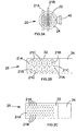
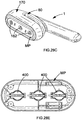
- the device includes a mist generator means which comprises a vibrating member which includes a metal or ceramic plate; the plate may be solid or porous, may contain passages or holes passing therethrough, be micropierced with perforations in the form of a grid or in the form of one or more segments or slots passing through the vibrating member, and a piezoelectric actuator which, when operated, causes vibratory motion in the vibrating member.
- the mist generator means may be an annular ring of a piezoelectric material which is attached to said vibrating member and spans the annulus, which when activated, causes the said vibrating member to vibrate.
- the mist generator means may comprise a piezoelectric material which is attached to, adjacent to or abutting a non-vibrating element or member which receives the vibratory motion of the piezoelectric material and transfers the vibratory motion to the said vibrating member.
- the mist generator comprises a piezoelectric material which is attached to, adjacent to or abutting a non-vibrating element or member which receives the vibratory motion of the piezoelectric material and forces the treatment composition through the vibrating member which optionally but not necessarily vibrates; where the mesh or plate does not vibrate the treatment composition is driven through the vibratory member by virtue of the movement of the attached to, adjacent to or abutting a non-vibrating element or member which receives the vibratory motion of the piezoelectric material, e.g. by compression of the treatment composition located between the non-vibrating member and the mesh or plate due to the vibratory motion of the piezoelectric material.
- the mist generator means may be a tubular piezoelectric material which includes a vibrating member spanning its interior bore between the ends of the piezoelectric material, and/or includes a vibrating member spanning the interior bore at one or more ends thereof, such that when activated the tubular piezoelectric material vibrates or expands/contracts which in turn imparts vibratory motion of the vibrating member(s).
- the mist generator means is provided as part of a refill unit or refill reservoir which, when inserted or affixed to the device completes the device and enables its use. Further the mist generator means may be user replaceable article or unit which may be removed and/or installed as needed or desired by a user to one or more of the device or the refill unit or refill reservoir.
- the mist generator may be formed of several parts which are required to be assembled in order to form an operating mist generator means, e.g., a piezoelectric actuator may form part of the device and a separate vibrating member form part of a refill unit or refill reservoir which remains inoperative until the device and refill unit or refill reservoir are properly aligned or otherwise installed in the device so permit the interaction between the piezoelectric actuator and the vibrating member which then operates as a mist generator means.
- a piezoelectric actuator may form part of the device and a separate vibrating member form part of a refill unit or refill reservoir which remains inoperative until the device and refill unit or refill reservoir are properly aligned or otherwise installed in the device so permit the interaction between the piezoelectric actuator and the vibrating member which then operates as a mist generator means.
- a new vibrating member is provided to the device.
- the device includes a controller means for controlling the operation of the mist generator means.
- the controller means may provide one or more functions.
- the controller means preferably includes a high frequency generator used to generate a suitable electrical signal for the operation of the mist generator, and particularly a piezoelectric element or device associated therewith.
- the controller means may include one or more switches, or other input means, e.g., buttons, contacts or switches, which can be established by user of a device according to the invention in order to control the mode of operation of the controller means.
- the controller means may also include means for controlling the output of the mist generator which may turn the unit off, or suspend its operation after a metered amount or dose of the treatment composition is dispensed from the device; the amount of the treatment composition may be a user controllable amount, e.g., via a setting, or may be a predetermined metered amount which cannot be changed by the user.
- the amount of treatment composition delivered by the device may be varied in response to a signal received by the controller means which may respond to an environmental condition of the device.
- the controller means may also be adapted to receive, and respond to, one or more signal inputs received from one or more sensors associated with the device.
- the controller means may be adapted to receive and respond to signals or conditions relating to the status of any part of the device such as the quantity of treatment composition in a reservoir or refill unit, to the physical orientation of the device, as well as to the frequency of dispensing and/or volume of treatment composition dispensed over a unit time interval.
- Nonlimiting examples of such responses include to increase or decrease one more of: the volumetric delivery rate of the treatment composition, and/or the frequency of delivery of the treatment composition per unit of time.
- the controller means may provide one or more output signals which may be transmitted to one or more further elements of the device via suitable conductor means, such as wires, in order to control their operation.
- the controller means may be programmable and include suitable electronic circuitry for the operation of the device according to one or more programs each having at least one, but preferably a plurality of, discrete programmed steps; typically such includes at least a logic or program controller, e.g., a central processing unit, and system memory for storing one or more programs.
- the controller means may be a non-programmable circuit, which preferably operates according to specific logic responsive to one or more signal inputs to the controller means.
- the controller means may comprise a drive circuit in order to provide suitable power and/or signal outputs to the mist generator in order to control its operation in generating a treatment mist from the fluid treatment composition, which may include known-art drive circuits suitable for this purpose.
- a suitable circuit which may be present within the controller means is a pulse-width-modulation circuit comprising a transformer converter and having an input acted on by a piezoelectric element present and the mist generator; such as disclosed in published application US 2009/0121043 .
- a further example of a suitable circuit is one which includes a microprocessor controlled variable oscillator for providing variable frequencies to mist generator such that treatment composition is formed into an aerosol of fine droplets.
- the variable oscillator preferably comprises a digital resistor for adjusting the time of charge and discharge; such a circuit is disclosed in US 7673812 .
- the device may be operated by direct control by a user, e.g., controlling a switch upon the device or alternately, the device may be operated indirectly, e.g., by a remote control unit.
- the device may include a power supply source which is integral to the device, e.g., one or more batteries, such that the device is portable, or the device may include means, e.g. wire, for connecting the device to a source of power, e.g., a transformer or electrical mains, supplying electrical power to the controller means.
- the batteries may be replaceable by the user when they are exhausted.
- the batteries may be rechargeable batteries which may be replenished by connecting them to a suitable power source.
- the device of the invention is fully portable, but in other embodiments the device of the invention or part thereof may be a stationary part which is not necessarily moved or portable when the device is in use. Such includes, e.g., a recharging station, or a part of the device which comprises the fluid reservoir. Further configurations of the device are also possible.
- the device may include one or more sensor means.
- Sensor means may be present to evaluate the state of a condition within the device, e.g., the presence of a treatment composition, or the presence of a suitable refill container.
- Sensor means may be present to evaluate the state of the environment in which the device is being used, e.g., time of day, degree of brightness near the environment of the device, absence of light, presence of light, a sound sensor, a vibration sensor, a heat sensor, an odor or scent sensor, a pressure sensor, a proximity sensor, and the like.
- the device may include a fill level sensor which controls the operation of the device responsive to the amount of liquid present in the device and/or in the reservoir, which may be a removable reservoir.
- the device may include one or more orientation sensing means for determining a physical orientation of the device, which for example, can be a level sensor, horizon sensor, accelerometer or any other device which can be used to establish the relative position of the device with respect to the horizontal or horizon.
- orientation sensing means for determining a physical orientation of the device, which for example, can be a level sensor, horizon sensor, accelerometer or any other device which can be used to establish the relative position of the device with respect to the horizontal or horizon.
- the device includes a removable reservoir which is intended to be removed from the device and replaced when necessary, such as to replenish or to resupply a new quantity of the treatment composition to the device.
- the reservoir of the device may be adapted to contain a single fluid treatment composition or may be adapted to contain a plurality of fluid treatment compositions.
- Such a removable reservoir may take the form of cartridge or assembly, or be a part of such a cartridge or assembly.
- the cartridge may be a single-use cartridge which is not intended to be refilled.
- the cartridge may include a bag or plenum which may optionally be vented to the atmosphere.
- the cartridge may be refillable by the user.
- the device may include at least one fluid control means for controlling the rate of delivery of a fluid product, viz., a treatment composition, from the reservoir to the mist generator.
- the fluid control means may form part of the device, or may be part of a removable reservoir, or may be present in both the device and a removable reservoir.
- the fluid control means may also be formed by cooperative elements, part of which are present on the removable reservoir and part on the device such that, when the cooperative elements are assembled, in conjunction they form a fluid control means.
- the device may include one, or several fluid control means.
- Nonlimiting examples of fluid control means include the following: a) one or more tubes or channels which provide fluid conduits to supply the treatment composition from the fluid reservoir to the mist generator means; b) one or more pumps, especially preferably one or more micropumps, c) direct physical interaction between a vibrating member and the treatment composition, e.g.
- the treatment composition is supplied to a top surface or bottom surface of the vibrating member during at least a portion of its range of vibratory (or oscillatory) movement, or during the range of vibratory (or oscillatory movement) the vibrating member contacts a quantity of the treatment composition and entrains it within the vibrating member before expelling it therefrom, such for example may occur wherein a tube having exposed treatment composition at an end thereof is in near proximity but not in direct contact with a vibrating member; d) by a gravity feed flow of the treatment composition to the mist generator means; e) a manual supply means, e.g., manual pumping by a user of an element such as a pump or bulb which transfers a quantity of the treatment liquid to the mist generator means; f) an antechamber or cavity which is intermediate the reservoir and the mist generator means which antechamber or cavity is first filled from the reservoir, and the mist generator means is supplied with treatment composition from the antechamber of cavity which had been previously supplied treatment composition from the reservoir.
- Particularly preferred fluid flow means include b) one or more pumps, including but not limited to: gear pumps, positive displacement pumps, rotary pumps, micropumps, diaphragm pumps, and especially preferably piezoelectric diaphragm pumps such as those presently commercially available from Bartels Mikrotechnik GmbH (Dortmund, Germany). Examples of such piezoelectric diaphragm pumps are disclosed in one or more of the following: WO/2009/059664 . Such number among particularly preferred embodiments of the invention.
- the device may include at least one fluid control means for controlling the rate of delivery of a fluid product (treatment composition) from the reservoir to the mist generator.
- the fluid control means may form part of the device, or may be part of a removable reservoir, or may be present in both the device and a removable reservoir.
- the fluid control means may also be formed by cooperative elements, part of which are present on the removable reservoir and part on the device such that, when the cooperative elements are assembled, in conjunction they form a fluid control means.
- the device may include one, or several fluid control means.
- the device may include an airflow generator means to increase the flowrate of the mist of the treatment composition.
- the airflow generator means may be used to generate a current of air which induces or directs the flow of the atomized treatment composition, and especially as it exits the device.
- the airflow generator means also entrains the nebulized or mist of the treatment composition and may be used to direct its flow outwardly from the device.
- such airflow generator means are absent and excluded form the device.
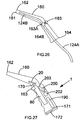
- the device may be a single unit which is substantially confined by a housing, or the device may include one or more extensible elements, e.g., a wand connected to the housing of the device which housing contains the mist generator and/or the reservoir.
- a part of the device contains the reservoir of the treatment composition and the mist generator means, which is connected by a tube through which the atomized treatment composition (mist of the treatment composition) passes to a further part of the device which may include a flow directing nozzle through which the atomized treatment composition exits the device; the user may position the device, and when present, the flow directing nozzle, in order to direct the flow of the atomized treatment composition onto a hard surface and/or onto a soft surface in order to treat the said surface.
- a flow directing nozzle is not required of all embodiments of the invention and may be excluded from the device, but may be present in certain preferred embodiments of the invention.
- the device may comprise further flow directing elements which cooperative with the flow directing nozzle in order to provide an ancillary flow directing benefit, or which provide means for interactively contacting the surfaces being treated.
- further flow directing elements are absent and excluded form the device.
- the device may further comprise an air-treatment means which is used to provide a volatile material to the ambient environment of the device, which volatile material is supplied to the ambient environment independently of the mist generator means.
- the air-treatment means may be used to deliver a volatile material, e.g., one or more of fragrances, perfumes, compositions for the control or eradication of airborne insects, odor neutralizing agents, odor masking agents, as well as those which may impart holistic or aromatherapy benefits which is separate from the treatment composition.
- a volatile material may be provided in a reservoir comprising a quantity of said volatile material which may form part of or be used with the device.
- Such a reservoir can take any shape or suitable form, and can be included within the interior of the device, or on the exterior of the device, or may be even be separate from the device but provided as a separate article or element which is separate or separable from the device but intended to be placed in the near proximity of the device.
- a reservoir may include a porous material such as a pad or tablet which is impregnated with, or upon which is absorbed a volatile composition useful in providing an air treatment benefit, a gel or a solid composition which also contains a volatile air treatment composition which may emanate to the ambient environment from the reservoir, or a container which includes a fibrous wick, or pad, or a porous membrane for the delivery of a volatile material to the ambient environment from the reservoir.
- the reservoir may contain a quantity of a particulate material in the form of a single body, e.g. plate, or as a plurality of spheres, or beads which function as a reservoir for the volatile composition, and from whence they may be delivered to the ambient environment.
- a particulate material in the form of a single body, e.g. plate, or as a plurality of spheres, or beads which function as a reservoir for the volatile composition, and from whence they may be delivered to the ambient environment.
- Non-limiting examples of such materials include those currently marketed under the tradename Auracell® (ex. Rotuba Extruders) which are based on fragranced cellulosic polymers, as well as PolyIFF® (ex. International Flavors and Fragrances Inc.), as well as Tenite® (ex. Eastman Chemical Co.).
- the device of the invention includes a mist generator means for the delivery of a treatment composition which comprises a treatment agent.
- the treatment composition may be solely comprised of the treatment agent.
- the mist generator may be any device which provides for atomization of the treatment composition or which provides for the aerosolization of the treatment composition without directly heating the treatment composition or utilizing a propellant gas or via the use of a liquid pump to directly drive the treatment composition through a nozzle and consequently cause the formation of discrete particles therefrom.
- the treatment composition may be provided in a ready to use form, e.g., does not require further dilution with water or other material in order to form the treatment composition to be atomized and dispensed from the device, or alternately may be provided in a concentrated form which requires further dilution with water or other material prior to its being atomized and dispensed from the device.
- the mist generator means is a nebulizer means, which is also generally preferred for use.
- Nebulizer means typically impart energy to the treatment composition wherein the ultrasonic energy is supplied via a transducer. This energy results in atomization of the treatment composition without requiring direct heating of the treatment composition or without the need for a propellant composition or a manually operated liquid pump to drive the treatment composition.
- Various types of nebulizers include, but are not limited to: ultrasonic, gas, venturi, nebulizers. Such may be obtained from a variety of commercial sources.
- Exemplary nebulizer means which are presently commercially available from Kai-Chih Industrial Ltd. (Taiwan) include those disclosed in one or more of US 6854662 ; a nebulizer and baffle plate assembly as disclosed in US 7229029 ; piezoelectric and percussion board assembly as disclosed in US 2007/0011940 ; a block piezoelectric actuator and vibratable plate as disclosed in US 2007/0169775 ; a vibration member comprising a piezoelectric ceramic actuator and a vibratory plate as disclosed in US 2008/00419272 .
- the mist generator means is energized from the power source and such causes a grid or plate to vibrate at a high frequency and concurrently to emit a cloud of very fine liquid particles, viz., a mist, which may then be omitted.
- the very fine liquid particles forming the mist of the treatment composition alternately referred to as a "treatment mist” typically have an average diameter which may be of relatively wide distribution, e.g, from about 0.25 microns to about 500 microns, however it is preferred that the particle size distribution of the fine liquid particles fall within the range of about 5 to about 300 microns, and especially preferably fall in the range of between about 10 to about 100 microns.
- the preponderance (> 75%, preferably >85%, especially preferably > 95%) of the very fine liquid particles forming the mist of the treatment composition is in the range of about 8 - 80 microns, and especially preferably about 10 - 50 microns.
- up to about 25%, preferably up to 10% of the very fine liquid particles forming the mist of the treatment composition is in the range of 0.1 - 10 microns, and up to about 25%, preferably up to 15% of the very fine liquid particles forming the mist of the treatment composition is in excess of 100 microns with the remaining at least 50%, but preferably at least 75% of the very fine liquid particles forming the mist of the treatment composition is in the range of 10 - 50 microns, and especially preferably in the range of 10 - 30 microns.
- not more than about 22%, 20%, 18%, 16%, 15%, 12%, 10%, 9%, 8%, 7%, 6%, 5%, 4%, 3%, 2%, 1% and most preferably essentially none (less than 0.5%) of the very fine liquid particles forming the mist of the treatment composition is in the range of 0.1 - 10 microns, and concurrently and in order of increasing preference, not more than about 22%, 20%, 18%, 16%, 15%, 12%, 10%, 9%, 8%, 7%, 6%, 5%, 4%, 3%, 2%, 1% and most preferably essentially none (less than 0.5%) of the very fine liquid particles forming the mist of the treatment composition is in excess of 50 microns, with the remaining balance to 100% of the very fine liquid particles forming the mist of the treatment composition within 10 microns and 50 microns.
- the particle size distribution may be directed to delivering having smaller average diameters than discussed above.
- the mist generator means is energized from the power source and such causes the grid to vibrate at a high frequency and concurrently to emit a cloud of very fine liquid particles, viz., a mist, which may then be omitted.
- the very fine liquid particles forming the mist of the treatment composition typically have an average diameter which may be of relatively wide distribution, e.g, from about 0.01 microns to about 200 microns, however it is preferred that the particle size distribution of the fine liquid particles fall within the range of about 0.1 to about 50 microns, and especially preferably fall in the range of between about 0.1 to about 25 microns, and particularly preferably from about 0.1 to about 15 microns.
- the preponderance (> 75%, preferably >85%, especially preferably > 95%) of the very fine liquid particles forming the mist of the treatment composition is in the range of 0.1 - 10 microns.
- not more than about 22%, 20%, 18%, 16%, 15%, 12%, 10%, 9%, 8%, 7%, 6%, 5%, 4%, 3%, 2%, 1% and most preferably essentially none (less than 0.5%) of the very fine liquid particles forming the mist of the treatment composition are in excess of 10 microns, with the remaining balance to 100% of the very fine liquid particles forming the mist of the treatment composition of 10 microns or less.
- a "bi-modal" distribution of very fine liquid particles are provided by a nebulizer, such that, opposed to many known nebulizers which provide a distribution of very fine liquid particles which are averaged about a median or averaged liquid particle size or liquid particle mass, in said preferred embodiment the nebulizer provides a bi-modal distribution of very fine liquid particles, a first part or proportion of the liquid particles being of a first particle size distribution which are averaged about a first median or first averaged liquid particle size or liquid particle mass, and a second part or proportion of the liquid particles being of a second particle size distribution which are averaged about a second median or second averaged liquid particle size or liquid particle mass.
- the average liquid particle size or liquid particle mass of the first median or first particle size distribution is lesser in average or median particle size or mass than the average liquid particle size or liquid particle mass of the second median or second particle size distribution.
- the provision of such a bi-modal distribution provides for a first part or portion of the liquid particles being of a smaller particle size, preferably having a first median or first averaged liquid particle size in the range of 1 - 10 microns, preferably 1 - 8 microns, yet more preferably between 2 - 7 microns, and a second part or portion of the liquid particles being of a relatively larger particle size, preferably having a second median or second averaged liquid particle size in the range of 10 - 50 microns, preferably 10 - 40 microns, yet more preferably between 10 - 35 microns.
- At least 60%, and in order of increasing preference, at least 70%, 75%, 80%, of the particles or mass of the liquid particles present within the first or second proportion are within +/- 35% by mass or size, and in order of increasing preference are within" +/-30%, +/- 25%, +/- 20%, +/- 15%, +/- 10% of their respective median or average liquid particle size or liquid particle mass.
- the mass of the particles delivered in the first part or portion of liquid particles is not more than about 1 ⁇ 2, preferably not more than about 1/4 of the mass of the mass of the particles delivered in the second part or portion of liquid particles, which have a larger average particle size or mass.
- the mass ratio of the particles delivered in the first part or portion of liquid particles to the particles delivered in the second part or portion of liquid particles is in the range of about 1:2, and in order of increasing preference is in the respective mass ratio about: 1:3, 1:4, 1:5, 1:6, 1:7, 1:8, 1:9, 1:10.
- the delivery of the liquid treatment composition as a bi-modal distribution of very fine liquid particles provides for controlled distribution of the treatment composition wherein a controlled mass, but visually very visible amount or mass, of the liquid treatment composition provided in the a first part or proportion of the liquid particles is delivered concurrently with greater mass of the liquid treatment composition provided in the a second part or proportion of the liquid particles.
- Mists of the treatment composition (interchangeably referred to as a treatment mist, TM) has several advantages.
- a first advantage is that it is flowing and somewhat buoyant, which permits for the deposition of the very fine liquid particles on surfaces which are not necessary adjacent to the outlet of a device from whence the mist is released. This may provide for a small degree of airborne drift and permit for improved deposition of the liquid particles as compared to liquids which may be applied via a manually pumped trigger sprayer, or even liquids dispensed from a pressurized aerosol container.
- the droplets of a liquid composition dispensed from a manually pumped trigger sprayer typically have larger average droplet sizes than those delivered by such a mist generator, and hence average droplet masses which concurrently transport and bombard a treated surface with greater amounts of a liquid composition per droplet.
- Such characteristics minimize the aerial buoyancy of the droplets, and when the droplets contact a surface the greater mass of liquid composition tends to much more quickly wet a surface, primarily by adsorption and to a lesser extent by absorption.
- both the larger and heaver particle sizes of the such liquid droplets, and their velocity as they are being released from a manually pumped trigger sprayer typically causes greater amounts of a liquid composition to be dispensed and faster wetting of surfaces.
- a liquid composition from a pressurized aerosol container typically results in similar delivery characteristics. While a critical selection of the orifice sizes and internal passages of an aerosol canister's spray actuator typically used with such pressurized aerosol container often provides somewhat more selection and control of the average droplet size, still the typical droplets of a liquid composition dispensed from a pressurized aerosol container also typically have larger average particle sizes than those delivered by such a generator, and hence have average droplet masses and greater distribution of average droplet sizes which concurrently transport and bombard a treated surface with greater amounts of a liquid composition per droplet.
- the treatment mist emitted from the mist generator in devices according to the invention may provide improved delivery to hard or non-porous surfaces, particularly when such may be associated with articles having three dimensional features, or which themselves have a three-dimensional, e.g., patterned, non-flat planar, or roughened surface.
- the irregularities in such surfaces may be very effectively treated by providing a mist from a device according to the invention, or according to a process of the invention in the near proximity or adjacent to such a surface, such that the delivered mist is permitted to settle and deposit upon such a three-dimensional surface.
- the delivery of the mist which is expected to be airborne for at least a few fractions of a second after being dispensed from a device, will often also exhibit a useful degree of airborne drifting prior to settling upon a treated surface.
- airborne drifting provides for improved coverage of hard surfaces, particularly when such are three-dimensional themselves or are associated with articles having three dimensional features.
- such may be a kitchen countertop or sink from which may extend a plumbing fixture, e.g., a faucet.
- a lavatory appliance e.g.
- a toilet, bidet, shower, bathtub, or bathroom sink which also includes elements, e.g., faucets, spouts, drains, handles and the like.
- the airborne drifting of the mist of the treatment composition is also very useful in delivering the treatment composition to open airspace, e.g., a room, a space within the interior of a building, a vehicle cabin or vehicle compartment, as well as within a closed container e.g., the interior of a storage cabinet, a closet, a shower stall, a garbage container or refuse bin, and the like.
- a treatment composition in the form of an airborne mist of the treatment composition which may be alternately characterized as a cloud of very fine liquid particles of the treatment composition provides for improved surface deposition on such surfaces, including that of such elements. Due to the airborne nature of this mist or cloud, the dispensed mist or cloud forms an enveloping body or penumbra of very fine liquid particles of the treatment composition which may first surround a surface or article, and then deposit thereon by settling of the very fine liquid particles.
- soft surfaces which are particularly beneficially treated by the use of a device of the invention or by practice of the inventive process are soft surfaces. Such soft surfaces often exhibit a degree of porosity thus permitting for the passage of gases therethrough. Frequently such also have internal spaces or interstices in their construction. Non-limiting examples of such soft surfaces include: textiles, carpets, garments, and the like.
- the delivery of a treatment composition via a mist or cloud such as described above typically provides improved penetration of the soft surface due to the drifting of, or penetration of such internal spaces or interstices in a soft surface, e.g., the space between fibers in a twisted yarn, the space between adjacent yarns in the pile or nap of a carpet, the space between fibers of a woven or non-woven textile, such that very fine liquid particles of the treatment composition may be transported into the interior of the soft surface prior to such a particle depositing on a surface.
- Such an effect might be referred to as an injection of the mist of very fine liquid particles of the treatment composition into the three dimensional matrix of a soft surface wherein at least a part of the emitted very fine liquid particles transit to the interior of the soft surface prior to contacting any part of the soft surface itself, and only thereafter come into contact with and are deposited in the soft surface.
- the delivery rates of the devices may vary in order to suit a specific application, e.g., it may be advantageously to have a higher delivery rate of the treatment composition per unit of time (e.g., seconds, minutes, hours, days) for spaces with larger volumes and/or wherein the device is located at a greater distance from the surface or surfaces to be treated, as opposed to closer placement and/or smaller volumes or spaced to be treated.
- the treatment mist dispensed from the device may be delivered at a rate of about 0.5 milliliter/minute to about 100 milliliter/ for most applications and uses.
- the delivery rate is from about 1 - 50, more preferably 1 - 25, still more preferably 1 - 10 and particularly preferably about 1 - 5 milliliter/minute.
- the treatment mist emitted from the mist generator in devices according to the invention may travel along a horizontal surface for a reasonable distance when exiting the device.
- the plume of the treatment mist emitted from the mist generator travels up to 60 cm in a lateral or horizontal direction perpendicular to the device, and preferably travels between 1 - 50 cm in such a direction as measured from where it exits the device.
- Such permits for the travel, distribution and contact of the treatment mist with surfaces having non-planar geometries, e.g., curved surfaces, as well as travel of the treatment mist to the sides of a surface being treated, including the underside and back sides of a surface being treated.
- a further important technical characteristic of the delivery of a treatment composition as an airborne mist of the treatment composition is that typically better surface coverage and a more uniform layer of a treatment composition is deposited on either a hard or soft surface, and thus the actual mass of a treatment composition may be reduced as compared to delivery of the same treatment composition via a manually pumped trigger sprayer or a pressurized aerosol container in order to achieve a comparable technical effect. More simply stated, less of the treatment composition is wasted due to excessive delivery or overspraying than when delivered as a mist or cloud of very fine liquid particles of the treatment composition.
- Providing a controlled amount of a treatment composition delivered as a mist or cloud of very fine liquid particles provides for minimization of localized delivery of the composition, e.g., as spots or zones of a treated soft surface which may quickly form a wetted or saturated part of the textile or surface which may result in wrinkling or staining of the area to which a composition has been applied, e.g., such as by a trigger sprayer or from a pressurized aerosol canister.
- the small degree of airborne drift of the treatment composition provided as a mist or cloud of very fine liquid particles provide for a more uniform distribution upon and possibly also within the textile or garment and thus permit for a reduction or minimization of the actual mass of the treatment composition which needs to be provided.
- a treatment composition which provides a cleaning or odor masking or odor neutralization benefit is delivered as a treatment mist, viz, a cloud of very fine liquid particles which is used to treat a garment or textile article in a sufficient amount in order to provided the desired cleaning or odor masking or odor neutralization benefit.
- a treatment mist viz, a cloud of very fine liquid particles which is used to treat a garment or textile article in a sufficient amount in order to provided the desired cleaning or odor masking or odor neutralization benefit.
- two or more of these benefits may be provided in the practice of the process for treating such soft surfaces.
- the device of the invention generates a treatment mist of discrete or aerosolized particles of the treatment composition which is used to treat surfaces, including inanimate hard surfaces and inanimate soft surfaces, as well as topical surfaces.
- the aerosolized form of a treatment composition comprises at least one treatment agent which ultimately contacts a surface being treated after being dispensed from the device of the invention.
- the treatment agent may be provided as a constituent of a treatment composition comprising further constituents other than the treatment agent, although a treatment composition consisting solely of a treatment agent is not excluded from the scope of the invention.
- the treatment composition comprises at least one treatment agent.
- the treatment composition provides a technical benefit to a hard surface or soft surface being treated.
- the treatment composition as applied to hard surfaces and/or soft surfaces may provide a technical benefit which may be transitory or durable.
- the treatment compositions may provide a surface coating to hard surfaces and/or to soft surfaces.
- the treatment composition may also reduce the buildup of biofilms on the treated surface.
- the treatment composition may deposit a coating on hard surface or soft surface which is hydrophilic in nature or hydrophobic in nature.
- Treatment compositions which are formed into treatment mists necessarily comprise an effective amount of one or more treatment agent within the treatment composition such that the desired technical benefit is provided when the treatment mist is applied to or into a hard surface or soft surface, or supplied in any other means or for any other use.
- the treatment composition Prior to being formed into a treatment mist form, the treatment composition is advantageously a flowable liquid at room temperature (20°C) and at normal atmospheric pressure in which the device of the invention finds use.
- the viscosity of the treatment composition is not necessarily critical, it only being required that it can be atomized in the device out of the invention and delivered as a mist of comminuted or aerosolized particles.
- the viscosity of the treatment composition falls within the range of about 0 - 2000 cP, preferably between about 0.5 - 1000 cP, and especially preferably between about 0.5 - 500 cP.
- Especially preferred embodiments of the treatment composition are free flowable liquids, i.e. are "water thin" and thus are readily flowable, as well as being readily pumpable either by mechanical means such as by a pump, or by capillary means such as within a narrow diameter tube, and which is also readily easily and effectively atomized by the mist generator means.
- the treatment composition includes a large proportion, that is to say at least about 50%wt. of a liquid.
- the treatment composition is at least 60%wt., and in order of increasing preference, 70%wt., 80%wt., 90%wt., 95%wt. 97%wt., 98%wt., 99%wt. and to 100%wt. of a liquid.
- the liquid is preferably a free-flowing liquid at room temperature and normal prevailing atmospheric conditions as noted above.
- the liquid may be water, or may be one or more non-aqueous solvents, e.g., one or more organic solvents, or may be a mixture or composition comprising both water and one or more further non-aqeuous solvents, e.g., one or more organic solvents.
- the water may be tap water, but is preferably distilled and is most preferably deionized water.
- exemplary useful organic solvents which may be included in the treatment compositions include those which are at least partially water-miscible such as alcohols (e.g., low molecular weight alcohols, such as, for example, ethanol, propanol, isopropanol, and the like), glycols (such as, for example, ethylene glycol, propylene glycol, hexylene glycol, and the like), water-miscible ethers (e.g. diethylene glycol diethylether, diethylene glycol dimethylether, propylene glycol dimethylether), water-miscible glycol ether (e.g.
- alcohols e.g., low molecular weight alcohols, such as, for example, ethanol, propanol, isopropanol, and the like
- glycols such as, for example, ethylene glycol, propylene glycol, hexylene glycol, and the like
- water-miscible ethers e.g. diethylene glyco
- propylene glycol monomethylether propylene glycol mono ethylether, propylene glycol monopropylether, propylene glycol monobutylether, ethylene glycol monobutylether, dipropylene glycol monomethylether, diethyleneglycol monobutylether), lower esters of monoalkylethers of ethylene glycol or propylene glycol (e.g. propylene glycol monomethyl ether acetate), and mixtures thereof.
- organic solvents One preferred organic solvent which may be included within the treatment compositions is triethylene glycol which is believed to provide odor sanitization or odor neutralizing benefits to an airspace within which culminated particles of triethylene glycol are present.
- triethylene glycol may be considered for its advantageous benefit. When present, it can be included in amounts effective to provide a desired degree of air sanitization. In certain embodiments it is also expressly contemplated that triethylene glycol is the preponderant constituent present, or even the sole treatment agent present in a treatment composition.
- the treatment composition may also include one or more surfactants.
- surfactants which are advantageously included to typically provide for the loosening of soils or other hydrophobic matter which may be present on a surface being treated with the device of the invention.
- Such surfactants may be selected from one or more of anionic, nonionic, cationic, amphoteric and zwitterionic surfactants. Such are per se, known to the art.
- anionic surfactants include sulfates and sulfonates of organic compounds, e.g., alkyl compounds.
- anionic surfactants include alkyl carboxylates, alkyl ether carboxylates, sulfosuccinates, taurates, alkyl phosphates, isethionates, alkylpolysaccharide sulfates, alkylpolyglucoside sulfates, sarcosinates or mixtures thereof.
- Anionic soaps may also be used in the inventive compositions. Examples of the foregoing anionic surfactants are available under the following tradenames: Rhodapon®, Stepanol®, Hostapur®, Surfine®, Sandopan®, and Biosofit® tradenames.
- Exemplary useful nonionic surfactants are those which include a hydrophobic base portion, such as a long chain alkyl group or an alkylated aryl group, and a hydrophilic chain portion comprising a sufficient number of ethoxy and/or propoxy moieties to render the nonionic surfactant at least partially soluble or dispersible in water.
- nonionic surfactants include ethoxylated alkylphenols, alkoxylated fatty alcohols, polyethylene glycol ethers of methyl glucose, polyethylene glycol ethers of sorbitol, ethylene oxidepropylene oxide block copolymers, ethoxylated esters of fatty (C 6 -C 24 ) acids, condensation products of ethylene oxide with long chain amines or amides, condensates of alkylene oxides, particularly ethylene oxide with sorbitan fatty acid esters, e.g., polyoxyethylene sorbitan monolaurate, polyoxyethylene sorbitan monopalmitate, polyoxyethylene sorbitan trioleates, alkoxylated alkanolamides, e.g.
- useful nonionic surfactants include materials are available under the Tomadol®, Neodol®, Rhodasurf®, Genapol®, Pluronic®, Lutensol®, Emulgen® and Alfonic® tradenames.
- nonionic surfactants include alkylmonoglycosides and alkylpolyglycosides are prepared generally by reacting a monosaccharide, or a compound hydrolyzable to a monosaccharide with an alcohol such as a fatty alcohol in an acid medium; examples include D-glucopyranoside, available as Glucopon® 625 CS which is described as being a 50% C 10 -C 16 alkyl polyglycoside.
- the treatment compositions may include one or more amphoteric surfactants, non-limiting examples of which are: derivatives of secondary and tertiary amines having aliphatic radicals that are straight chain or branched, and wherein one of the aliphatic substituents contains from about 8 to 18 carbon atoms and at least one of the aliphatic substituents contains an anionic water-solubilizing group, e.g., a carboxy, sulfonate, or a sulfate group, such as sodium 3-(dodecylamino)propionate, and sodium 3-(dodecylamino)propane-1-sulfonate, sarcosinates, taurates, amide sulfosuccinates, and betaines including phosphobetaines.
- amphoteric surfactants non-limiting examples of which are: derivatives of secondary and tertiary amines having aliphatic radicals that are straight chain or branched, and
- the treatment composition may also comprise one or more cationic surfactant constituents, especially preferably one cationic surfactants which provide an appreciable germicidal benefit.
- cationic surfactant compositions which may be included in the treatment compositions are those which provide an appreciable germicidal benefit, and especially preferred are quaternary ammonium compounds and salts thereof, which may be characterized by the general structural formula: where at least one of R 1 , R 2 , R 3 and R 4 is a alkyl, aryl or alkylaryl substituent of from 6 to 26 carbon atoms, and the entire cation portion of the molecule has a molecular weight of at least 165.
- the alkyl substituents may be long-chain alkyl, long-chain alkoxyaryl, long-chain alkylaryl, halogen-substituted long-chain alkylaryl, long-chain alkylphenoxyalkyl, arylalkyl, etc.
- the remaining substituents on the nitrogen atoms other than the abovementioned alkyl substituents are hydrocarbons usually containing no more than 12 carbon atoms.
- the substituents R 1 , R 2 , R 3 and R 4 may be straight-chained or may be branched, but are preferably straight-chained, and may include one or more amide, ether or ester linkages.
- the counterion X may be any salt-forming anion which permits water solubility or water miscibility of the quaternary ammonium complex.
- Preferred quaternary ammonium compounds which act as germicides according to the foregoing formula are those in which R 2 and R 3 are the same or different C 8 -C 12 alkyl, or R 2 is C 12-16 alkyl, C 8-18 alkylethoxy, C 8-18 alkylphenolethoxy and R 3 is benzyl, and X is a halide, for example chloride, bromide or iodide, or is a methosulfate anion.
- the alkyl groups recited in R 2 and R 3 may be straight-chained or branched, but are preferably substantially linear.
- Particularly useful quaternary germicides include compositions which include a single quaternary compound, as well as mixtures of two or more different quaternary compounds.
- Such useful quaternary compounds are available under the BARDAC®, BARQUAT®, HYAMINE®, LONZABAC®, and ONYXIDE® trademarks.
- one or more cationic surfactants which provide an appreciable germicidal benefit may be present as a co-antimicrobial agent, with a further antimicrobial agent described hereinafter.
- cationic surfactants which provide an appreciable germicidal benefit are present, preferably anionic surfactants and further optionally, amphoteric surfactants are omitted from the treatment compositions of the invention.
- Other surfactants although not specifically disclosed herein but known to the art may also be used within the treatment compositions of the present invention.
- the treatment of the compositions may also include one or more fluorosurfactants, non-limiting examples of which include the anionic salts of perfluoroaliphaticoxybenzene sulfonic acids and the anionic salts of linear perfluoroalkyl-oxybenzoic acids/
- fluorosurfactants include the anionic salts of perfluoroaliphaticoxybenzene sulfonic acids and the anionic salts of linear perfluoroalkyl-oxybenzoic acids/
- fluorosurfactants are compounds according to the following structures and descriptions:
- Fluorinated hydrocarbon surfactants are available from numerous commercial sources as trademarked products. Examples are ZONYL fluorosurfactants from E.I. duPont de Nemours & Co., FLUORAD fluorosurfactants from 3M Company, e.g., FLUORAD FC-129 (R f SO 2 N(C 2 H 5 ) CH 2 CO 2 - K + , where R f is C n F 2n+1 and n is about 8),
- the treatment compositions may comprise further antimicrobial agents other than the one or more cationic surfactants described above.
- Such an antimicrobial agent is/are one or more compounds other than cationic surfactants which provide an appreciable germicidal benefit, viz., cationic germicide, described above.
- Such an antimicrobial agent desirably provides an effective antimicrobial benefit to a treated surface, other than a cationic germicide, preferably such that the treatment composition delivered by the device of the invention exhibits at least 3 log 10 kill efficacy, preferably at least 4 log 10 kill efficacy at 60 seconds contact time of at least two, preferably at least three and most preferably at least four of microorganisms selected from the group consisting of: S . aureus, E. coli, P.
- aeruginosa and E.hirae desirably according accepted and standardized testing protocols for the evaluation of antimicrobial efficacy of a composition applied to a hard surface, soft surface, or a dermal surface, i.e. a human or animal epidermis.
- the antimicrobial agent may include one or more of: pyrithiones such as zinc pyrithione, halohydantoins such as dimethyldimethylol hydantoin, methylchloroisothiazolinone/methylisothiazolinone sodium sulfite, sodium bisulfite, imidazolidinyl urea, diazolidinyl urea, benzyl alcohol, 2-bromo-2-nitropropane-1,3-diol, formalin (formaldehyde), iodopropenyl butylcarbamate, chloroacetamide, methanamine, methyldibromonitrile glutaronitrile, glutaraldehyde, 5-bromo-5-nitro-1,3-dioxane, phenethyl alcohol, o-phenylphenol/sodium o-phenylphenol, sodium hydroxymethylglycinate, polymethoxy bicyclic ox
- the antimicrobial agent may include one or more of: biguanides such as polyhexamethylene biguanide, p-chlorophenyl biguanide; 4-chlorobenzhydryl biguanide, 1,6-bis-(4-chlorobenzylbiguanido)-hexane (Fluorhexidine®), halogenated hexidine including, but not limited to, chlorhexidine (1,1'-hexamethylene-bis-5-(4-chlorophenyl biguanide)(Chlorohexidine®), as well as salts of any of the foregoing, e.g. polyhexamethylene biguanide hydrochloride.
- biguanides such as polyhexamethylene biguanide, p-chlorophenyl biguanide
- 4-chlorobenzhydryl biguanide 1,6-bis-(4-chlorobenzylbiguanido)-hexane
- the treatment compositions of the invention may also comprise one or more organic or inorganic acids which may be used to adjust the pH of the treatment composition to a target range or level, and/or to impart an antimicrobial benefit.
- the acids may be one or more of a water soluble inorganic acids, mineral acids, or organic acids, with virtually all such known materials contemplated as being useful in the treatment compositions.
- useful inorganic acids include mineral acids, hydrochloric acid, phosphoric acid, sulfuric acid, and the like.
- the inventive compositions comprise one or more organic acids which may be used to adjust the pH of the treatment composition, and which optionally may also provide an antimicrobial benefit.
- organic acids are those which generally include at least one carbon atom, and include at least one carboxyl group (--COOH) in its structure. Derivatives of said organic acids are also contemplated to be useful.
- Exemplary organic acid include linear aliphatic acids such as acetic acid; dicarboxylic acids, acidic amino acids, and hydroxy acids such as glycolic acid, lactic acid, hydroxyacrylic acid, alpha-hydroxybutyric acid, glyceric acid, malic acid, tartaric acid and citric acid, as well as acid salts of these organic acids.
- salicylic acid derivatives such as esters of salicylic acid, such as ethylhexyl salicylate, dipropylene glycol salicylate, TEA salicylate, salicylic acid 2-ethylhexylester, salicylic acid 4-isopropyl benzylester, salicylic acid homomenthylester are preferred.
- the treatment composition may comprise a peroxygen compound which may be essentially any compound containing a dioxygen (O--O) bond.
- Dioxygen bonds particularly bivalent O--O bonds, are readily cleavable, thereby allowing compounds containing them to act as powerful oxidizers.
- classes of peroxygen compounds include peracids, peracid salts, and peroxides such as hydrogen peroxide.
- the peroxygen can be any aliphatic or aromatic peracid (or peroxyacid) that is functional for disinfectant purposes in accordance with embodiments of the present invention. While any functional peroxyacid can be used, peroxyacids containing from 1 to 7 carbons are the most practical for use.
- peroxyacids can include, but not be limited to, peroxyformic acid, peroxyacetic acid, peroxyoxalic acid, peroxypropanoic acid, perlactic acid, peroxybutanoic acid, peroxypentanoic acid, peroxyhexanoic acid, peroxyadipic acid, peroxycitric, and/or peroxybenzoic acid.
- Exemplary peracid salts include permanganates, perborates, perchlorates, peracetates, percarbonates, persulphates, and the like.
- Exemplary peroxide compounds include hydrogen peroxide, metal peroxides and peroxyhydrates.
- the metal peroxides that can be used include, but are not limited to, sodium peroxide, magnesium peroxide, calcium peroxide, barium peroxide, and/or strontium peroxide.
- Other salts for example sodium percarbonate
- hydrogen peroxide associated therewith are also considered to be a source of hydrogen peroxide, thereby producing hydrogen peroxide in situ.
- the treatment compositions of the invention may also include an oxidizing agent which may be a halogen bleach.
- the oxidizing agent is a halogen bleach source which may be selected from various hypohalite-producing species, for example, bleaches selected from the group consisting of the alkali metal and alkaline earth salts of hypohalite, haloamines, haloimines, haloimides and haloamides. All of these are believed to produce hypohalous bleaching species in situ.
- the oxidizing agent is a hypohalite or a hypohalite generator capable of generating hypohalous bleaching species.
- hypohalite is used to describe both a hypohalite or a hypohalite generator, unless otherwise indicated.
- the hypohalite oxidizing agent is a hypochlorite or a generator of hypochlorite in aqueous solution, although hypobromite or a hypobromite generator is also suitable.
- Hypochlorite generators include sodium, potassium, lithium, magnesium and calcium hypochlorite, chlorinated trisodium phosphate dodecahydrate, potassium and sodium dichloroisocyanurate and trichlorocyanuric acid.
- Organic bleach sources suitable for use include heterocyclic N-bromo and N-chloro imides such as trichlorocyanuric and tribromocyanuric acid, dibromocyanuric acid and dichlorocyanuric acid, and potassium and sodium salts thereof, N-brominated and N-chlorinated succinimide, malonimide, phthalimide and naphthalimide.
- hydantoins such as dibromodimethyl-hydantoin and dichlorodimethyl-hydantoin, chlorodimethylhydantoin, N-chlorosulfamide (haloamide) and chloramine (haloamine).
- the hypohalite oxidizing agent is an alkali metal hypochlorite, an alkaline earth salt of hypochlorite, or a mixture thereof.
- the treatment composition of the invention may include a treatment agent which provides an anti-static or surface softening benefit to a surface, particularly a textile or fibrous surface being treated.
- a treatment agent which provides an anti-static or surface softening benefit to a surface, particularly a textile or fibrous surface being treated.
- treatment agents for providing a fiber, textile or fabric softening benefit are one or more compounds which are known to the art as fabric softener compounds.
- fabric softener compounds include all the current commercial quaternary long-chain softeners, and preferably at least partially unsaturated esterquats.
- Exemplary suitable fabric softeners include fabric softening compounds which are cationic, water insoluble quaternary ammonium compounds comprising a polar head group and two long hydrocarbyl moieties, preferably selected from alkyl, alkenyl and mixtures thereof, wherein each such hydrocarbyl moiety has an average chain length equal to or greater than C 12 , preferably greater than C 14 , more preferably greater than C 16 , More preferably still, at least 50% of each long chain alkyl or alkenyl group is predominantly linear.
- a preferred overall chain length is about C 18 , though mixtures of chain lengths having non-zero proportions of lower, e.g., C 14 , C 16 and some higher, e.g., C 20 chains may be desired.
- the cationic softener can suitably be distearyl dimethyl ammonium chloride or unsaturated analogs thereof, but preferably the selected quaternary ammonium fabric softener is biodegradable. Such a property is common to many commercial esterquat fabric softeners such as di(tallowyloxyethyl)dimethyl ammonium chloride.
- the fabric softening compound is a quaternary ammonium esterquat compound having two C 12-22 alkyl or alkenyl groups connected to a quaternary ammonium moiety via at least one ester moiety, preferably two such ester moieties. Of course mixtures of two or more fabric softener compounds.
- the treatment compositions of the invention may also include a treatment agent which provides an air treatment technical benefit.
- a treatment agent which provides an air treatment technical benefit.
- such include fragrances, perfumes, compositions for the control or eradication of airborne insects, odor neutralizing agents, odor masking agents, as well as those which may impart holistic or aromatherapy benefits.
- a fragrance may form part of the treatment composition, and which may be based on natural and synthetic fragrances and most commonly are mixtures or blends of a plurality of such fragrances, optionally in conjunction with a carrier such as an organic solvent or a mixture of organic solvents in which the fragrances are dissolved, suspended or dispersed.
- a fragrance constituent may be present in the treatment composition in any effective amount.
- the fragrance or perfume is present in amounts of from about 0.0000 1%wt. to about 50%wt. based on the total weight of the treatment composition of which they form a part, although, due to the mode of delivery of the mist generator means to which does not impart thermal degradation of such a constituent, its inclusion in even higher amounts to about 100%wt. of the treatment composition are also contemplated as being possible and indeed advantageous in certain embodiments of the invention.
- the treatment composition of the invention may include one or more holistic constituents, particularly may include one or more essential oils which are selected to provide a so-called "aromatherapy benefit" to the user.
- essential oils are frequently extracted from naturally occurring botanical sources such as flowers, stems, leaves, roots and barks of aromatic plants.
- fragrance compositions which may also include one or more essential oils, frequently, due to their potency, essential oils are often supplied dispersed in a liquid carrier such as in one or more organic solvents in which the essential oils are dissolved or dispersed.
- Preferred essential oils providing an aromatherapy benefit include one or more selected from chamomile oil, lavendin oil, lavender oil, grapefruit oil, lemon oil, line oil, mandarin orange oil, orange flower oil and orange oil.
- these one or more essential oils providing an aromatherapy benefit are present in any effective amount, advantageously are present in amounts of from about 0.00001%wt. to about 50%wt. based on the total weight of the treatment composition of which they form a part, although, due to the mode of delivery of the mist generator means to which does not impart thermal degradation of such a holistic constituent or essential oils, their inclusion in even higher amounts to about 100%wt. of the treatment composition are also contemplated as being possible and indeed advantageous in certain embodiments of the invention. It is to be understood that these one or more essential oils providing an aromatherapy benefit may be used with our without the optional fragrancing constituent recited previously and alternately, may be used wholly or partially in place of said fragrancing constituent.
- the treatment compositions according to the invention optionally but desirably include an amount of a pH adjusting agent or pH buffer composition.
- a pH adjusting agent or pH buffer composition include many which are known to the art and which are conventionally used.
- pH adjusting agents include phosphorus containing compounds, monovalent and polyvalent salts such as of silicates, carbonates, and borates, certain acids and bases, tartrates and certain acetates.
- Further exemplary pH adjusting agents include mineral acids, basic compositions, and organic acids, which are typically required in only minor amounts.
- pH buffering compositions include the alkali metal phosphates, polyphosphates, pyrophosphates, triphosphates, tetraphosphates, silicates, metasilicates, polysilicates, carbonates, hydroxides, and mixtures of the same.
- Certain salts such as the alkaline earth phosphates, carbonates, hydroxides, can also function as buffers. It may also be suitable to use as buffers such materials as aluminosilicates (zeolites), borates, aluminates and certain organic materials such as gluconates, succinates, maleates, and their alkali metal salts.
- compositions according to the invention include an effective amount of an organic acid and/or an inorganic salt form thereof which may be used to adjust and maintain the pH of the treatment compositions of the invention to the desired pH range.
- the treatment compositions of the invention may also include one or more alkanolamines which in addition to providing an improved cleaning benefit may also be used to concurrently adjust the pH of the treatment composition.
- alkanolamines such as monoalkanolamines, dialkanolamines, trialkanolamines, and alkylalkanolamines such as alkyl-dialkanolamines, and dialkyl-monoalkanolamines.
- the alkanol and alkyl groups are generally short to medium chain length, that is, from 1 to 7 carbons in length.
- the treatment compositions of the invention may also comprise one or more hydrotropes, preferably one or more anionic hydrotrope compounds.
- exemplary hydtropes include, e.g., , benzene sulfonates, naphthalene sulfonates, C 1 -C 11 alkyl benzene sulfonates, naphthalene sulfonates, C 5 -C 11 alkyl sulfonates, C 6 -C 11 alkyl sulfates, alkyl diphenyloxide disulfonates, and phosphate ester hydrotropes.
- Particularly useful hydrotrope compounds include benzene sulfonates, o-toluene sulfonates, m-toluene sulfonates, and p-toluene sulfonates; 2,3-xylene sulfonates, 2,4-xylene sulfonates, and 4,6-xylene sulfonates; cumene sulfonates, wherein such exemplary hydrotropes are generally in a salt form thereof, including sodium and potassium salt forms.
- a bore, cavity or other configuration other than a weir with at least one sloping sidewall may be used as part of the atomizing chamber 45 as disclosed in several of the following figures.
- a further embodiment of an atomizing chamber 45 present within the first body part 40A here a generally circular bore 42 having a base 44 opposite from an open and 48.
- a vibrating plate 22 and a piezoelectric element 24 as depicted on Fig. 4 .
- a supply of the treatment composition TC enters the atomizing chamber 45 via fluid conduit and above the vibrating plate 22 such that it contacts the top face 22b.
- FIG. 15 also illustrates a sensor means, here a mist sensor means.
- the mist sensor means 71 includes a transmitter unit 71A and a receiver unit 71A mounted transversely from each other across the bore 45 and preferably near the open end 48 thereof.
- the transmitter unit generates a signals, e.g. such as optical, acoustic, or other signal capable of being received by the receiver unit, and any variations in the quality of the signal being transmitted due to the quantity or quality of the presence of the atomized particles, viz, mist, of the treatment composition passing through the gap between the transmitter unit 71A and receiver unit 72B, as represented by arrow 73 is detected by the receiver unit.
- a signals e.g. such as optical, acoustic, or other signal capable of being received by the receiver unit, and any variations in the quality of the signal being transmitted due to the quantity or quality of the presence of the atomized particles, viz, mist, of the treatment composition passing through the gap between the transmitter unit 71A and receiver unit 72B, as represented by arrow 73 is detected by the receiver unit.
- An appropriate signal can be transmitted to the controller means (not shown) which may initiate a responsive action by the controller means and one or more further parts of the device.
- a signal representative of this state may be transmitted to the controller means which for example may increase the power or alternately increase the frequency signal being transmitted to the piezoelectric elements 24 to thereby increase the rate of its oscillation or vibration, and/or alternately the mass flow rate of the treatment composition TC, such as may be supplied via a pump, may be increased.
- the mist sensor means may also determine if the atomizing chamber 45 is flooded with the fluid form of the treatment composition and upon sending a signal to the control unit representative thereof, the control unit may cause an appropriate response, e.g., shutting down of the device or interrupting the operation of the mist generator 20.
- the mist sensor means may also determine the absence or presence of the mist of the treatment composition within the atomizing chamber 45, and if the latter is sensed then a representative signal may be sent to the control unit may cause an appropriate response, e.g., shutting down of the device or interrupting operation of the mist generator 20.
- suitable electrical or signal unit conducting means i.e. wires, may be used to connect the various elements of the mist sensor means, the fluid control means, the controller means, as well as any other device, elements or parts of the device as may be required, although such is not necessarily illustrated in the figures presented herein.
- Figures A1 and A2 illustrate by means of graphical representations preferred treatment mist particle size or particle mass bi-modal distributions.
- Figure A1 represents the mass distribution or % distribution of the size (in microns) of the discrete liquid droplets being dispensed by a mist generator, during normal steady state operation over a convenient time interval, e.g., 1 or more seconds, or one or more minutes..
- a greater amount of particles in the range of 0 - 10 microns are dispensed than the amount of particles in the range of 10 - 20 microns, whereas the amount of particles in the successive ranges of 20-30 microns is greater than those dispensed in the prior two ranges.
- FIG. A1 illustrates two further alternative bi-modal distributions according to preferred embodiments of the invention, here represented as a first bi-modal distribution represented by "C1" (in solid line) and a second bi-modal distribution represented by "C2" (in dotted line). The curves represent the distribution, by %wt.
- the first median or first averaged liquid particle size corresponds to line segment C11, which is approximately at 4 microns with the particle size distribution within the first part of the bi-modal distribution being beneath the curved line C1 to the left and right of the line segment C11
- the second median or second averaged liquid particle size corresponds to line segment C12, which is at approximately 29 microns, with the particle size distribution within the second part of the bi-modal distribution being to the left and right of the line segment and beneath curved line C1.
- first median or first averaged liquid particle size corresponds to line segment C21, which is approximately at 5 microns with the particle size distribution within the first part of the bi-modal distribution being beneath the curved line C2 to the left and right of the line segment C21
- second median or second averaged liquid particle size corresponds to line segment C22, which is at approximately 22 microns, with the particle size distribution within the second part of the bi-modal distribution being to the left and right of the line segment and beneath curved line C2.
- Figures 13A and 13B depict a preferred embodiment of a mist generator assembly 400 comprising a mist generator means 20 which includes a vibrating plate 22 affixed, bonded to or otherwise mounted on a peripheral piezoelectric element similar in most respects to embodiments discussed with reference to Figs. 1, 2 , 2A , and/or 4 although other mist generator means not specifically disclosed may be adapted for use.
- the mist generator assembly 400 includes a first body element 40A having an open end 48 across which spans and is mounted the mist generator means 20, here wherein the peripheral edge 26 of the piezoelectric element 24 is mounted within the bore 42 of the first body element 40A and defines an atomizing chamber 45, and which also defines a base cavity 46 within the first body element 40A rearward or inwardly of the mist generator means 20.
- the mist generator means 20 is mounted to the first body element 40A in a liquid, seal-tight manner.
- a pair of electrical current carrying means 40 or, namely a pair of wires which supply an electrical current from the circuit control means (not shown) which acts to operate the mist generator means 20 by inducing the vibrations within that the vibrating plate 22 which acts to pump the mist of the treatment composition TM from the mist generator assembly 400;
- the means 40 may pass through a part of the first body element 40A via a suitable perforation or channel or pathway or for that matter by any other suitable arrangement of the elements of the mist generator assembly 400.
- a fluid conduit 30 which has an open end 32 which extends into the base cavity 46 via a supply bore 31 into which the treatment composition TC is provided from the fluid conduit 30 by any suitable means, e.g., capillary flow, gravity flow but most preferably via pump intermediate the reservoir of the treatment composition and the mist generator assembly 400.
- the controller means is operated to control the volumetric flow rate of the pump means used to supply the treatment composition to the base cavity 46, as well as concurrently controlling the operation of the mist generator means 20 and its output such that a satisfactory delivery rate of the treatment mist TM is generated, and concurrently a sufficient amount of the treatment composition TC is supplied to the mist generator assembly 400 such that the an ample supply of the TC is present therein, but at the same time pumping of an excess of the treatment composition TC and "flooding" of the base cavity 46 is desirably avoided.
- Figure 20E illustrates a bottom plan view of the mist generator assembly 400 illustrating the arrangement of the mist generator means 20, the plate 22 including microperforations, or holes or passages 21 passing therethrough.
- first body element 40A may be formed or fabricated from any suitable material, such as a metal, synthetic polymer, ceramic material, and the like advantageously at least the part of the first body element 40A of the mist generator assembly 400 to which the mist generator means 20 is fixed is at least elastomeric or partially elastomeric in nature.
- the advantage of such construction allows for the mist generator assembly 400 used in any variety of orientations as will be described in greater detail in later figures.
- the first body element 40A is flexible or elastomeric at least at the region of the interface between the mist generator means 20 and the first body element 40A, such permits for the easy installation or mounting of the mist generator means 20 when the region of the interface between the mist generator means 20 and the first body element 40A can be stretched or distended to permit for the installation of the mist generator means 20, and when the region is permitted to return to its original orientation, a liquid-tight seal is formed between the first body element 40A and the mist generator means 20.
- the first body element 40A of the mist generator assembly 400 and be constructed or formed of a monolithic mass of an elastomeric material such as a rubber, silicone, or other flexible material which can simultaneously be used to mount and retain the mist generator means 20 in the manner depicted.
- an elastomeric material such as a rubber, silicone, or other flexible material which can simultaneously be used to mount and retain the mist generator means 20 in the manner depicted.
- parts of, or all of the first body element 40A also acts to absorb vibratory shocks emanating from the operating mist generator means 20 to other parts of the device, and/or to be felt by the user of the device.
- the first body element 40A is wholly formed of a flexible or elastomeric material.
- FIG. 14 A further embodiment of a mist generator means is depicted in Fig. 14 , which is similar in most respects to the embodiment illustrated in Figs. 13A and 13B .
- the embodiment of Fig. 14 differs primarily in that the mist generator assembly 400 is formed of a conjoined first body element 40A and a second body element 40B via set of mating screw threads 40S.
- the mist generator means 20 which includes a vibrating plate 22 affixed, bonded to or otherwise mounted on a peripheral piezoelectric element similar in most respects to embodiments discussed with reference to Figs. 1, 2 , 2A , and/or 4 although other mist generator means not specifically disclosed may be adapted for use.
- the material of construction of the first body element 40A and the second body element 40B is not necessarily an elastomeric or flexible material but is depicted to be a rigid material.
- a rigid material can be for example a ceramic, metal, but is advantageously a synthetic polymer which can be easily injection molded, shape, or otherwise formed, and which is also nonporous thereby useful in retaining the treatment composition TC within its interior, especially within the base cavity 46.
- the first body element 40A has a horn-shaped or cone-shaped open end 48 across which spans and is mounted the mist generator means 20, here wherein the peripheral edge 26 of the piezoelectric element 24 is mounted between two elastomeric sealing members, here illustrated as two O-rings, 40R1 and 40R2 which provide a liquid tight seal between the mist generator means 20 and the first body element 40A and the second body element 40B when they are assembled.
- the mist generator means 20 is mounted to the first body element 40A in a liquid, seal-tight manner via the two elastomeric sealing members.
- This positioning also defines an atomizing chamber 45 forwardly or outwardly of the mist generator means 20, and which also defines a base cavity 46 within the second body element 40B rearward or inwardly of the mist generator means 20.
- a pair of electrical current carrying means 40 or, namely a pair of wires which supply an electrical current from the circuit control means (not shown) which acts to operate the mist generator means 20 by inducing the vibrations within that the vibrating plate 22 which acts to pump the mist of the treatment composition TM from the mist generator assembly 400; the means 40 (wires) may pass through a part of the first body element 40A and/or second body element 40B via a suitable perforation or channel or pathway or for that matter by any other suitable arrangement of the elements of the mist generator assembly 400.
- a fluid conduit 30 which has an open end 32 which extends into the base cavity 46 via a supply bore 31 into which the treatment composition TC is provided from the fluid conduit 30 by any suitable means, e.g., gravity flow but most preferably via a pump intermediate the reservoir of the treatment composition and the mist generator assembly 400.
- the controller means is operated to control the volumetric flow rate of the pump means used to supply the treatment composition to the base cavity 46, as well as concurrently controlling the operation of the mist generator means 20 and its output such that a satisfactory delivery rate of the treatment mist TM is generated, and concurrently a sufficient amount of the treatment composition TC is supplied to the mist generator assembly 400 such that the an ample supply of the TC is present therein, but at the same time pumping of an excess of the treatment composition TC and "flooding" of the base cavity 46 is desirably avoided.
- FIG. 15 A further embodiment of a mist generator means is depicted in Fig. 15 , which is similar in most respects to the embodiment illustrated in Figs. 13A, 13B and 14 .
- the embodiment of Fig. 15 differs primarily in that the mist generator assembly 400 is formed of a conjoined first body element 40A and a second body element 40B via compression-type fitting therebetween which is facilitated as in this preferred embodiment the first body element 40A is formed of a flexible elastomeric material.
- the first body element 40A functions as a mounting frame for the mist generator means 20, which includes a vibrating plate 22 affixed, bonded to or otherwise mounted on a peripheral piezoelectric element similar in most respects to embodiments discussed with reference to Figs.
- the material of construction of the second body element 40B is not necessarily an elastomeric or flexible material but is depicted to be a rigid material.
- the rigid material is a synthetic polymer which can be easily injection molded, shape, or otherwise formed, and which is also nonporous thereby useful in retaining the treatment composition TC within its interior, especially within the base cavity 46.
- the first body element 40A has a horn-shaped or cone-shaped open end 48 across which spans and is mounted the mist generator means 20, here wherein the peripheral edge 26 of the piezoelectric element 24 is mounted within a circumferential recess 40R which encases the peripheral edge 26 and which provides a liquid tight seal therebetween.
- the first body element 40A also forms a liquid tight seal with the second body element 40B when these elements are assembled.
- the first body element 40A includes a sloping exterior sidewall 40AF which extends at least into the region exterior of the a circumferential recess 40R which encases the peripheral edge 26 and the second body element 40B includes a corresponding sloping interior sidewall 40BF which comes into contact with the first body element 40A.
- the dimensions of the first body element 40A and the second body element 40B are such that a slight compression is imparted to the first body element 40A when it is inserted into the second body element 40B such that the former is seeded into the latter and forms a liquid tight seal there with and simultaneously compressive forces exist within the first body element and particularly in the region of the circumferential recess 40R which functions to both seat and seal the mist generator means 20 therein.
- the mist generator means 20 is mounted to the first body element 40A in a liquid, seal-tight manner with in the mist generator assembly 400.
- This positioning also defines an atomizing chamber 45 forwardly or outwardly of the mist generator means 20, and which also defines a base cavity 46 within the second body element 40B rearward or inwardly of the mist generator means 20.
- a pair of electrical current carrying means 40 or, namely a pair of wires which supply an electrical current from the circuit control means (also not shown) which acts to operate the mist generator means 20 by inducing the vibrations within that the vibrating plate 22 which acts to pump the mist of the treatment composition TM from the mist generator assembly 400;
- the electrical current carrying means 40 e.g., wires
- a fluid conduit 30 which has an open end 32 which extends into the base cavity 46 via a supply bore 31 into which the treatment composition TC is provided from the fluid conduit 30 by any suitable means, e.g., gravity flow but most preferably via a pump intermediate the reservoir of the treatment composition and the mist generator assembly 400.
- an overflow conduit 46C which extends into the base cavity 46, and had shown is connected to an overflow tube 47T which may be used to further direct the exiting treatment composition TC away from the mist generator assembly 400.
- the controller means is operated to control the volumetric flow rate of a pump means used to supply the treatment composition to the base cavity 46, as well as concurrently controlling the operation of the mist generator means 20 and its output such that a satisfactory delivery rate of the treatment mist TM is generated, and concurrently a sufficient amount of the treatment composition TC is supplied to the mist generator assembly 400 such that the an ample supply of the TC is present therein, but at the same time pumping of an excess of the treatment composition TC and "flooding" of the base cavity 46 is desirably avoided.
- excess treatment composition TC be present within the mist generator assembly 400 and particular within the base cavity 46, such excess treatment composition TC can be withdrawn and removed via the overflow tube 47T.
- Figures 16A, 16B and 16C illustrate in several views a further preferred embodiment of a mist generator assembly 400 which includes many of the features discussed with reference to prior Figures 13A, 13B , 14 and 15 .
- the mist generator assembly 400 includes a first body element 40A having an open end 48 across which spans and is mounted the mist generator means 20, here wherein the peripheral edge 26 of the piezoelectric element 24 is mounted within the bore 42 of the first body element 40A and defines an atomizing chamber 45, and also defines a base cavity 46 within the first body element 40A and rearward of the mist generator means 20.
- the mist generator means 20 is mounted to the first body element 40A in a liquid, seal-tight manner. Further illustrated are a pair of electrical current carrying means 40, e.g., a pair of wires which supply an electrical current from the circuit control means (not shown) which acts to operate the mist generator means 20 by inducing the vibrations within that the vibrating plate 22 which acts to pump the mist TM of the treatment composition from the mist generator assembly 400; the means 40 (wires) may pass through a part of the first body element 40A via a suitable perforation, or may otherwise pass outwardly from the mist generator assembly 400 by any other path.
- a pair of electrical current carrying means 40 e.g., a pair of wires which supply an electrical current from the circuit control means (not shown) which acts to operate the mist generator means 20 by inducing the vibrations within that the vibrating plate 22 which acts to pump the mist TM of the treatment composition from the mist generator assembly 400; the means 40 (wires) may pass through a part of the
- a trough 46T within the first body element 40A extending from the base cavity 46 inwardly, that is to say in a direction away from the mist generator means 20 within which, when the mist generator assembly 400 is fully or partially inverted, some of the treatment composition TC may collect within the trough 46T.
- the mist generator assembly 400 further comprises an overflow conduit 46C which is in fluid communication with the trough 46T such that, any of the treatment composition TC which may be present within the trough 46T may be drawn off, or otherwise exit the mist generator assembly 400 therethrough.
- the overflow conduit 46C is further connected to a suitable overflow tube 47T which may be used to further direct the exiting treatment composition TC away from the mist generator assembly 400.
- a fluid conduit 30 having an open end 32 extends into the base cavity 46 of the mist generator assembly 400 into which the treatment composition TC is provided via the said fluid conduit 30 by any suitable means, e.g., capillary flow, gravity flow but again, most preferably is supplied via a pump or pumps intermediate the reservoir of the treatment composition and the mist generator assembly 400.
- any suitable means e.g., capillary flow, gravity flow but again, most preferably is supplied via a pump or pumps intermediate the reservoir of the treatment composition and the mist generator assembly 400.
- the controller means is operated to control the volumetric flow rate of the pump means used to supply the treatment composition to the base cavity 46, of the mist generator assembly 400 as well as concurrently controlling the operation of the mist generator means 20 and its output such that a satisfactory delivery rate of the treatment mist TM is generated, and concurrently a sufficient amount of the treatment composition TC is supplied to the mist generator assembly 400 such that the an ample supply of the TC is present therein, but at the same time pumping of an excess of the treatment composition TC and "flooding" of the base cavity 46 is desirably avoided.
- FIG 16B illustrates a bottom plan view of the mist generator assembly 400 illustrating the arrangement of the mist generator means 20, the plate 22 including microperforations or passages 21 passing therethrough, the mist generator means 20 mounted within the bore 42 at the peripheral edges 26 of the plate.
- Figure 16C illustrates in a perspective view, the base of the mist generator assembly 400, albeit with the depiction of the mist generator means 20 removed for the purposes of clarity in this figure.
- the trough 46T is concentric and extends around the supply bore 31 through which the treatment composition TC been provided from the fluid conduit 30 passes into the base cavity 46.
- FIGS 17A, 17B, and 17C depict a mist generator assembly 400 generally as described with reference to Fig. 16A in three different modes of operation of the vibrating plate 22 of the mist generator means 20.
- the mist generator assembly 400 is oriented with respect to the horizontal, which is represented by line "H".
- a quantity of treatment composition TC as represented by the labeled arrows supplied via the fluid conduit 30 into the base cavity 46.
- the rate of delivery of the treatment composition TC is controlled such that the volume of the treatment composition TC present within the base cavity 46 does not fill it, and a headspace "HS" above the treatment composition TC within the base cavity 46 is present.
- the vibrating plate 22 is extended outwardly as shown, and particles of the treatment mist TM are generated.
- the vibrating plate 22 of the mist generator means 20 is at its intermediate position.
- the vibrating plate 22 is extended (flexed) inwardly and shown, causing the level of the treatment composition TC within the base cavity 64 to rise slightly, however a sufficient headspace HS exists within the base cavity 64 the mist generator assembly 400 is not flooded and it operates normally.
- Figures 18A, 18B and 18C depict a mist generator assembly 400 generally as described with reference to Fig. 16A , as well as with reference to Figs. 17A, 17B and 17C .
- the vibrating plate 22 is depicted in three different states but oscillates at a different frequency as shown in prior Figs. 17A, 17B and 17C ..
- the operating characteristics of the plate 22 differs, e.g. vibrates or oscillates differently, still in each configuration there remains a sufficient headspace HS within the base cavity 64 the mist generator assembly 400 is not flooded and it operates normally.
- the different oscillatory pattern of the vibrating plate 22 provided different pattern of delivery of the mist of the treatment composition TM.
- Figures 19A, 19B, 19C, 19D, and 19E respectively to pick the mist generator assembly 400 according to Fig. 16A in five different orientations or, namely in Fig. 19A in an upright vertical orientation, viz., 90° upward with respects to the horizontal, in Fig. 19B in an upwardly inclined orientation, viz., at approximately 45° with respect to the horizontal, in Fig. 19C in a horizontal orientation, viz., at 0° with respect to the horizontal, in Fig. 19D in a downwardly inclined orientation, viz. at approximately 45° below, and with respect to the horizontal, and finally in Fig.
- each orientation is indicated by the respective line labeled "H" in the figures.
- Fig. 19A as visible there from the treatment composition TC is pumped through the fluid conduit 30 into the mist generator assembly 400.
- Part of the treatment composition TC occupies part of the base cavity 64, while the remainder of the base cavity 64 comprises the headspace HS above the treatment composition TC.
- the mist of the treatment composition TM is formed and exits in a horizontal direction away from the mist generator assembly 400.
- any excess treatment composition TC from within the base cavity 64 may exit (in the direction of the arrow labeled "OF") outwardly from the mist generator assembly 400 via the overflow conduit 46C.
- treatment composition TC pumped through the fluid conduit 30 and present within the base cavity 64 occupies part of the base cavity 64, the remaining part of which is unoccupied forms the headspace HS above the treatment composition TC.
- a mist of the treatment composition TM is formed and exits the mist generator assembly 400 downward angled direction.
- Any excess treatment composition TC from within the base cavity 64 may exit the mist generator assembly 400 in the direction of the arrow labeled "OF" via the overflow conduit 46C.
- treatment composition TC pumped through the fluid conduit 30 and present within the base cavity 64 occupies part of the base cavity 64, the remaining part of which is unoccupied forms the headspace HS above the treatment composition TC.
- a mist of the treatment composition TM is formed and exits the mist generator assembly 400 downwardly. Any excess treatment composition TC from within the base cavity 64 may exit the mist generator assembly 400 in the direction of the arrow labeled "OF" via the overflow conduit 46C.
- treatment composition TC pumped through the fluid conduit 30 and present within the base cavity 64 occupies part of the base cavity 64, the remaining part of which is unoccupied forms the headspace HS above the treatment composition TC.
- a mist of the treatment composition TM is formed and exits the mist generator assembly 400 downwardly in an angled direction. Any excess treatment composition TC from within the base cavity 64 may exit the mist generator assembly 400 via the overflow conduit 46C.
- Fig. 19E in this downward vertical orientation, treatment composition TC pumped through the fluid conduit 30 and present within the base cavity 64 occupies part of the base cavity 64, the remaining part of which is unoccupied forms the headspace HS above the treatment composition TC.
- a mist of the treatment composition TM is formed and exits the mist generator assembly 400 in a horizontal direction. Any excess treatment composition TC from within the base cavity 64 may exit the mist generator assembly 400 via the overflow conduit 46C.
- the embodiment of the mist generator assembly 400 is relatively insensitive as to its orientation with respect to the environment, and/or with respect to the surface to be treated utilizing a device of the invention, as regardless of its orientation it will remain operative as long as a sufficient quantity of treatment composition TC is present within the interior of the mist generator assembly 400, or namely within the base cavity 64 such that while the vibrating plate 22 of the mist generator means 20 operates, a treatment mist TM can be formed and delivered from the mist generator assembly 400.
- overflow conduit 46C in fluid communication with the base cavity 64, here via the trough 46T (although trough is not required) permits for means of also ensuring that the base cavity 64 is not flooded with excess treatment composition TC.
- the egress of any excess treatment composition TC may be controlled by the placement of the overflow conduit 46C, and indeed a plurality of overflow conduits 46C is foreseen.
- the rate of egress of treatment composition from an overflow conduit 46C may be controlled such as by providing a downstream valve, or other flow controlling or flow directing means (not shown).
- the controller (not shown) and/or pump (not shown) may be used to control the volumetric supply rate of the treatment composition via the fluid conduit 30, and/or the volumetric egress rate of overflow treatment composition exiting the mist generator assembly 400 such that on the one hand a sufficient quantity of treatment composition TC is present within the base cavity 64 and in contact with the vibrating plate 22 when the mist generator 20 operates, and at the same time an excessive amount of the treatment composition TC is not present within the base cavity 64 such that the undesired flooding of the mist generator assembly 400 and especially the mist generator 20 is avoided irregardless of the orientation of the mist generator means with respect to the horizontal.
- mist generator assembly 400 which does not include an overflow conduit, such as the embodiment of the mist generator assembly 400 depicted in Fig. 20D and 20E.
- careful control of the ingress or supply of treatment composition TC is required in order to provide optimal operating characteristics, and minimize the likelihood of flooding.
- Figures 20A, 20B and 20C illustrated several alternative views a preferred embodiment of a mist generator assembly 400 similar in most respects to the embodiment of Fig. 16A .
- the first body element 40A has mounted therein a mist generator means 20 which abuts against a base cavity 64.
- a supply fluid conduit 30 extends into the base cavity 64, and an overflow conduit 46C is also in fluid communication with the base cavity 64 via a part of the trough 46T.
- the mist generator means 20 is in a sealed tight connection with the first body element 40A and is retained therein by a pair of extending lobes 402 which are made of a flexible elastomeric material and, in the embodiment depicted the entire first body element 40A is formed of a flexible or elastomeric material, here are preferably formed of a rubber-like material, which may for example be a rubber, a silicone material, silicon elastomer, or for that matter any other elastomeric material which provides both structural, and fluid sealing surfaces which can be used to both retain, to form a liquid tight seal between the first body element 40A and the mist generator means 20.
- a rubber-like material which may for example be a rubber, a silicone material, silicon elastomer, or for that matter any other elastomeric material which provides both structural, and fluid sealing surfaces which can be used to both retain, to form a liquid tight seal between the first body element 40A and the mist generator means 20.
- FIG. 20B illustrates the mist generator assembly 400 and its elements in a perspective view; also visible is a wire cavity "WP" within which the wires 40 (or other electrical current carrying conductors) connected to the mist generator means 20 may exit the mist generator assembly 400.
- Fig. 20C depicts the same as generator assembly 400 in a plan view.
- Figure 21 illustrates a representational view of a pair of mist generator assemblies 400, preferably one or more of the mist generator assemblies according to Figures 20D, 16A , 1811, 20J1, and/or 20A affixed to a mounting plate "MP" forming part of the device of the invention.
- a pair of fluid control means 90 which may be any device which may impart control over the quantity or quality of the fluid treatment composition passing outwardly from a reservoir 80.
- the reservoir 80 may be a refillable reservoir, a removable refill package, a cartridge, or any other vessel for containing a quantity of the treatment composition TC.
- the fluid control means nine your most conveniently a pair of pumps, especially preferably a pair of piezoelectric pumps which can be operated by and controlled by the controller means (not shown) in order to supply controlled amounts of the treatment composition TC to each of the mist generator assemblies 400.
- the amount of treatment composition supply to each of the mist generator assemblies 400 is not necessarily the same, but can vary in response to input from the controller but, in many operations or operating modes such will be essentially identical.
- the controller (not shown) operates the fluid control means 90, and did the mist generator assemblies 400 in order to generate plumes of mist of the treatment composition TM which exit the mist generator assemblies 400 via horns or other perforations PP within the mounting plates PM.
- FIG 22 illustrates one embodiment of a device 1 according to the present invention.
- the device 1 includes a first assembly 120 which includes a quantity of fluid treatment composition TC within a reservoir 80, a mist generator 20 submerged within the treatment composition TC which is attached to a controller means 140 by means of an intermediate wire or wires at 150, over which are also transmitted the power required to drive the mist generator 20.
- the first assembly 120 is openable via a top cover 122, which has passing therethrough two connector ports, an airflow inlet connector port 123 and a mist output connector port 124.
- an airflow generator means which provides a stream of a gas, preferably air via the airflow tube 123A which generates an elevated pressure within the interior of the vessel 80.
- the treatment composition in the form of a mist TM present within the vessel 80 is forced out via the mist tube 124A which directs it to the control handle 160 or control "wand", which has a flow directing nozzle 162 at its a distal end 161 from which the mist of the treatment composition TM emanates.
- the control handle 160 is gripped by a person and as the mist tube 124A is flexible and separate from the first assembly 120 it can be conveniently used to deliver a quantity of the mist of the treatment composition TM to a desired location.
- Fig. 23 illustrates an alternative embodiment of a first assembly 120, which is a self-contained, in that the controller means, power supply source, and airflow generator are contained in the housing 129 forming a part of the first assembly 120, for example, a battery powered blower or fan may be used in providing sufficient pressure within the interior of the reservoir 80 so to cause the flow of the mist of the treatment composition through the mist tube 124A.
- a self-contained first assembly provides for a more portable device 1 according to the invention.
- Fig. 24 depicts a device according to the invention which includes the first assembly 120 as generally depicted with reference to Fig. 25 , to which is attached a flexible strap 128 which can be used to hang the first assembly 120 from a body part such as a shoulder.
- the device 1 also includes a control handle 160 connected to the first assembly 120 by an intermediate, flexible mist tube 124A, from which the treatment composition in the form of the mist can be delivered.
- a control button 163 they be used to control the release the treatment composition from the flow directing nozzle 162.
- Fig. 25 illustrates a further embodiment of a device 1 according to the invention wherein in the first assembly 120 is provided on a wheeled cart 125, such as may be desired when a large amount of the treatment composition in the form of the mist is required to be dispensed.
- the depicted embodiment is similar in most respects to that described on Fig. 24 ; the figure also illustrates the manner in which a "soft surface" can be treated, here illustrated as a hanging curtain TS.
- a user merely directs the release of the aerosolized treatment composition, namely the treatment mist TM from the flow directing nozzle 162 of the control handle 160.
- Fig. 26 illustrates in a cross-sectional view a simple embodiment of a control handle 160 or control "wand” according to the prior embodiment of Figures 24 and 25 .
- the mist tube 124 enters through the proximal end 164 of the control handle 160, and extends to a release valve 163A which can be manually controlled by the control button 163, so that when the release valve 163A is in an "open" condition, the mist of the treatment composition flows through a nozzle tube 124B and to the flow directing nozzle 162, from whence the aerosolized or mist of the treatment composition exits.
- Manual gripping of the control handle 160 they be improved by providing a number of gripping the recesses 164B for cradling one or more fingers of a human operator holding and operating in the control handle 160.
- FIG. 27 illustrates a cross-sectional view of a further embodiment of a device 1 in a self-contained and portable assembly.
- a shaped housing 170 includes at one end a flow directing nozzle 162 which is in communication with the interior of the housing 170, and at the opposite end includes a removable cover 171 through which a reservoir 80 and a power supply source 190, here one or more electrical batteries, may be inserted within the shaped housing 170.
- an air intake grille 172 is also present in the housing 170 and preferably it is formed at or near the opposite end of the flow directing nozzle.
- a control circuit means (not shown), and airflow generator, here in the form a blower 200 which is driven by a small electrical motor 202 which is suitably mechanically coupled to the drive shaft (not shown) of the blower 200.
- a supply means 70 extends outwardly from the reservoir 80 and is sufficiently proximate to a mist generator 20 such that, upon activation thereof a mist TM of aerosolized treatment composition present within the interior of the reservoir is generated.
- the blower 200 directs a stream of moving air from its outlet 203 and inducing its to flow out from the flow directing nozzle 162 of the device 1.
- Such a device is portable, and compact, and also practical as frequently one or more treatment operations can be performed without requiring either replenishment or replacement of the reservoir 80, and or replacement or recharging of the one or more batteries 190. Furthermore, as the generation of a mist of the treatment composition is essentially nearly instantaneous with the activation of the mist generator 20, power can be spared in-between surface treatment operations as control button 163 which energizes the control means and consequently the blower 200 and the mist generator 20 need only be used to activate and operate the device 1 when actually treating a surface.
- FIGs. 28A, 28B , 28C , 28D illustrate views of a preferred embodiment of a device 1 in a self-contained and portable embodiment.
- a shaped housing 170 includes a plurality of flow directing nozzles 162 which extend through a mounting plate MP forming part of the housing 170, behind each of which nozzles 162 is mounted three mist generating assemblies 400 which are generally as described with reference to Figs. 20A, 20B and 20C .
- Also illustrated both mounted and unmounted in the device 1 is a cartridge shaped reservoir 80 which is fitted into the housing 170.
- the device 1 includes a a slideable switch 163A which may be operated by a user to control the operation of the device 1.
- a power supply source preferably one or more electrical batteries, (rechargeable, or non-rechargeable), control circuit means (not shown), and at least one, but may also be two or more pumps and necessary tubing or other fluid conduits in order to provide for supply of the treatment composition present within the cartridge shaped reservoir 80 to be supplied to each of the mist generator means 20 of each of the three mist generating assemblies 400 in response to appropriate control signals from the control circuit means which concurrently also operates the mist generator 20 and the one or more pumps, preferably piezoelectric diaphragm pumps such as those presently commercially available from Bartels Mikrotechnik GmbH.
- a power supply source preferably one or more electrical batteries, (rechargeable, or non-rechargeable), control circuit means (not shown), and at least one, but may also be two or more pumps and necessary tubing or other fluid conduits in order to provide for supply of the treatment composition present within the cartridge shaped reservoir 80 to be supplied to each of the mist generator means 20 of each of the three mist generating assemblies 400 in response to appropriate control signals from
- the mist generator assemblies 400 may be any other mist generating assembly 400 which may operate in accordance to the principles outlined in one or more of Figs. 19A, 19B, 19C, 19D and 19E .
- the use of one or more, here three, mist generator assemblies 400 permits the device 1 may be operated in a variety of inclinations or orientations with respect to the horizontal as previously described.
- Such also dispenses for any need of an airflow generator means to increase the flowrate of the mist of the treatment composition as the mist generator means 20 dispense the mist of the treatment composition TM directly outwardly from the mounting plate MP. Accordingly in preferred embodiments devices of the invention exclude such an airflow generator means.
- Figure 28E illustrates a part of the device 1 depicted in figures Figs. 28A, 28B , 28C , 28D .
- Figure 28E illustrates and plan view the mounting plate MP as viewed from within the interior of the device 1. As visible thereon, three mist generating assemblies 400 are arrayed in a generally linear arrangement are a fixed or otherwise mounted to the mounting plate MP.
- Figure 28F illustrates a cross-sectional view of the device according to Figs. 28A, 28B , 28C , 28D and 28E according to line "DD" of Fig. 28D .
- the mounting plate MP is positioned on the underside of the device 1 and op. cit. the handle 160 which is inclined with respect thereto.
- the handle 160 is grippable and suited to be grasped by the hand of a user.
- the three mist generator assemblies 400 are arranged such that treatment composition generated therefrom pass through the mounting plate MP and the flow directing nozzles 162 formed as part thereof; here the flow directing nozzles are simple orifices or holes passing therethrough with either straight, or slightly tapered sidewalls to impart a "horn-like" shape.
- each of the mist generator assemblies 400 are connected to further elements of the device including but not limited to a power supply source, preferably one or more electrical batteries, a control circuit means, and at least one pump and necessary tubing or other fluid conduits in order to provide for supply of the treatment composition present within the cartridge shaped reservoir 80 to be supplied to each of the mist generator means 20 each of the three mist generating assemblies 400 in response to appropriate control signals from the control circuit means which concurrently also operates the mist generator 20 and the one or more pumps.
- a power supply source preferably one or more electrical batteries, a control circuit means, and at least one pump and necessary tubing or other fluid conduits in order to provide for supply of the treatment composition present within the cartridge shaped reservoir 80 to be supplied to each of the mist generator means 20 each of the three mist generating assemblies 400 in response to appropriate control signals from the control circuit means which concurrently also operates the mist generator 20 and the one or more pumps.
- the device 1 may include an openable cover part which can be hinged, or removable and replaceable, such as to permit access to the interior of the device 1 particularly in a location wherein replaceable batteries may be positioned, such that their removal and replacement with fresh batteries can be facilitated.
- part of the handle 160 may include such an openable cover part, allowing access to the interior especially were one or more batteries are present within the handle.
- other types of switches may be included as well as a plurality of switches or sliders or other signal input means may also be provided.
- Such switches may be movable between two or more positions, and in its most simplest form operates only as an "on" and "off' switch, but preferably includes a least one or more intermediate settings.
- the one or more intermediate settings can be used to establish various operating parameters of the device 1, such as controlling the rate of delivery of the mist of the treatment composition, timer means to automatically engaged, and disengage operation of the device 1 at one or more preselected intervals of time and thereby providing for unattended operation of the device 1, or other operating parameters.
- the device 1 may also include one or more status indicator means, which provide visual feedback to the user of the device.
- Bonlimiting examples include light emitting diodes, or a small LCD or LED panel which are properly displays symbols relevance to the operating status of the device, such as pictographs, icons, written words, numerical indicators, and the like.
- the status indicator means can be any visually discernible, audio discernible, tactile discernible indicators which provide information regarding the status of the device including the operating status of the device 1 to a user.
- Such a device 1 is portable, compact, and also practical, as frequently one or more treatment operations can be performed without requiring either replenishment or replacement of the reservoir 80, and or replacement or recharging of the one or more batteries. Furthermore, as the generation of a mist of the treatment composition is essentially nearly instantaneous with the activation of the mist generator 20, and the direction of the directional delivery of the mist of the treatment composition may vary widely, the device 1 is both effective and convenient in use.
- Figure 29 depicts a simplified manner of treating a textile surface, here the upholstered surface of a chair TU.
- a device according to the invention 1 e.g., the embodiment according to Figs. 28A, 28B , 28C , 28D , 28E and 28F is operated such that the aerosolized treatment composition, namely the mist TM is used to contact the textile surface by appropriate placement of the device 1 while it operates.
- the mist of the treatment composition TM not only contacts the surface of the textile, but may also penetrate into and through the textile to provide a technical benefit, e.g., cleaning, sanitizing, disinfecting, fragrancing, deodorizing, odor neutralizing, anti-allergen, therapeutic, and/or other technical benefit.
- Figure 30 depicts a simplified manner of treating a hard surface, here a tiled ceramic surface, e.g. a kitchen countertop, a shower stall, a bathtub surround, or a flooring or wall surface.
- a device 1 according to the invention e.g., the embodiment according to Figs. 28A, 28B , 28C , 28D , 28E and 28F is operated such that the aerosolized treatment composition, namely the mist of the treatment composition TM is used to contact the hard surface by appropriate placement of the device 1 in proximity to the hard surface while it operates. Due to the airborne nature of the mist of the treatment composition TM, it typically remains airborne or floats for at least several seconds before evenly depositing upon surfaces in the locus in which it has been applied.
- the device of the invention may be used to treat the interior and contents of a clothes washing machine as well as a clothes dryer and the device may be used prior to a clothes washing or drying cycle, during a clothes washing or drying cycle, or after a clothes washing or drying cycle to release a treatment mist TM therefrom.
- the device of the invention may be used to treat textiles and garments, especially stains on clothing and garments particularly localized stains. Such a treatment to prior to a clothes washing or drying cycle, during a clothes washing or drying cycle, or after a clothes washing or drying cycle.
- the treatment of such textiles and garments may provide a cleaning benefit, a fragrancing benefit, in order neutralizing benefit, or for that matter any other technical benefit as may be desired or necessary.
- the device of the invention may be used to treat cookware, dishware, serving ware, eating utensils, tableware, and the like.
- the device may be operated to dispense a mist of a treatment composition onto such articles at any desired time.
- a treatment may occur prior to subjecting cookware, dishware, serving ware, eating utensils, and/or tableware to a subsequent washing operation, especially subject to a wash operation in an automatic dishwashing machine.
- such a treatment may curse subsequent to a washing operation, and the device is used to provide a treatment benefit, e.g., a surface coating, a layer of a sanitizing or disinfecting composition, onto surfaces of cookware, dishware, serving ware, eating utensils, tableware.
- a treatment benefit e.g., a surface coating, a layer of a sanitizing or disinfecting composition, onto surfaces of cookware, dishware, serving ware, eating utensils, tableware.
- a device according to the invention may be installed within the interior of a ware washing machine, e.g. an automatic dishwashing machine, in order to dispense a mist of a treatment composition thereto during part of a dishwashing cycle.
- the device can be permanently fixed therein, or can be removably affixed thereto such as by means of a suitable mounting bracket such that it is removable by the user should the device require refilling the fresh quantity of the treatment composition TC, or for servicing.
- a device according to invention can be supplied as a unit which can be removably inserted by being laid within or suspended from a rack as is conventionally present in a dishwashing machine.
- the device can operate in response to an appropriate input, such as a sensor signal including but not limited to time, temperature, chemical composition of the wash liquor present within the ware washing machine such that in response thereto, the device operates in order to deliver a quantity of the mist of the treatment composition TM to the interior of the ware wash machine and its contents.
- an appropriate input such as a sensor signal including but not limited to time, temperature, chemical composition of the wash liquor present within the ware washing machine such that in response thereto, the device operates in order to deliver a quantity of the mist of the treatment composition TM to the interior of the ware wash machine and its contents.
- the device according to the invention may be installed into the interior of a clothes washing machine and/or a clothes dryer.
- the device can be permanently affixed therein, or can be removably affixed thereto such as by means of a suitable mounting bracket such that it is removable by the user should the device require refilling the fresh quantity of the treatment composition TC, or for servicing.
- a device according to invention can be supplied as a unit which can be removably inserted within a clothes washing machine and/or a clothes dryer.
- the device can operate in response to an appropriate input, such as a sensor signal including but not limited to time, temperature, chemical composition of the wash liquor present within the ware washing machine such that in response thereto, the device operates in order to deliver a quantity of the mist of the treatment composition TM to the interior of the ware wash machine and its contents.
- an appropriate input such as a sensor signal including but not limited to time, temperature, chemical composition of the wash liquor present within the ware washing machine such that in response thereto, the device operates in order to deliver a quantity of the mist of the treatment composition TM to the interior of the ware wash machine and its contents.
- the device of the invention may be used to treat the interior and contents of a shower stall.
- a process and device of the invention can be used to deliver a mist of the treatment composition TM wherein a user of the device manually brings the device into the interior of the shower stall and/or surfaces thereof and operates the device in order to dispense the treatment mist TM.
- the device may be retained within the interior of the shower stall, e.g., suspended from a shower head or shower head supply pipe by a suitable hanger means, or may be adhered to a part of the shower stall by one or more suction or adhesive means wherein the device can be suitably mounted, preferably removably mountable in such a manner.
- the device may thereafter be preprogrammed, or manually operated as desired in order to release a quantity of the mist of the treatment composition TM in order to treat surfaces on the interior and contents of the shower stall.
- a timer means is included within the control circuitry in order to automatically initiate the operation of the device and its dispensing of the mist of treatment composition TM on a time-based periodic basis, or alternately made be cost operating response the receipt of a suitable signal.
- the device further includes an air-treatment means which provides an anciallary air treatment benefit.
- the device of the invention may be used to treat the interior of a refuse container, such as a garbage can, or garbage bin whether such be lined or online.
- the device may be affixed, or suspended cry part of the waste receptacle, e.g., by means of a suitable hanger, such that a quantity of the mist treatment composition TM at least periodically is released into the interior of the waste receptacle, and/or in the near proximity of the waste receptacle.
- the waste receptacle includes a movable lid and the device can be mounted thereupon.
- the device is mounted by means of a hanger, such that the device is within the interior of the waste receptacle.
- mist of the treatment composition TM is directed into the interior of the waste receptacle and then can be used to treat the refuse or other contents of the waste receptacle either on a time-based, periodic basis, in response to a signal of a signal means, and/or in response to a user input which may activate the device.
Claims (3)
- Dispositif permettant de générer un brouillard d'une composition de traitement afin de conférer une dénaturation d'allergènes bénéfique à une surface ou à un espace aérien, le dispositif pouvant être entièrement tenu à la main et comprenant :une chambre d'atomisation (45) comprenant une cavité de base (46) opposée à une extrémité ouverte (48) ;un moyen générateur de brouillard (20) s'étendant sur l'extrémité ouverte (48) et comprenant un élément vibrant qui inclut une plaque en métal ou en céramique (22), ladite plaque (22) étant pleine, poreuse ou micropercée sous la forme d'une grille ou sous la forme d'un ou plusieurs segments (23) ou fentes traversant l'élément vibrant ;un actionneur piézoélectrique (24) qui, lorsqu'il est actionné, provoque un mouvement de vibration dans l'élément vibrant ;un circuit de commande pour faire fonctionner le moyen générateur de brouillard (20) ;un réservoir (80) contenant un produit fluide à aérosoliser ;un moyen de pompe pour alimenter la cavité de base (46) avec le produit fluide provenant du réservoir (80) ;un boîtier ; etau moins une buse de direction d'écoulement (162), un instrument de direction d'écoulement ou un orifice de direction d'écoulement adapté pour diriger l'écoulement d'un brouillard généré par le moyen générateur de brouillard (20) hors du boîtier (129) vers une surface ou dans un espace aérien ou les deux, dans lesquels :le réservoir (80) du dispositif est une unité de recharge ;l'unité de recharge ne comprend pas l'actionneur piézoélectrique (29) ;l'unité de recharge comprend l'élément vibrant ; etle dispositif est conçu de telle sorte que, lorsque l'unité de remplissage est correctement installée dans le dispositif, l'actionneur piézoélectrique (24) et l'élément vibrant interagissent pour former le moyen générateur de brouillard (20),caractérisé en ce que le moyen de pompe est conçu pour réguler le débit de distribution du produit fluide afin de maintenir un espace vide (HS) au-dessus du produit fluide dans la cavité de base (46).
- Procédé de traitement d'une surface dure ou d'une surface molle inanimée, lequel procédé comprend les étapes consistant à : fournir un dispositif selon la revendication 1 et faire fonctionner le dispositif pour générer un brouillard d'une composition de traitement, laquelle composition de traitement entre en contact avec une ou plusieurs surfaces dures ou molles et offre un avantage technique à celles-ci.
- Utilisation d'un dispositif selon la revendication 1 pour le traitement d'un espace aérien.
Applications Claiming Priority (2)
| Application Number | Priority Date | Filing Date | Title |
|---|---|---|---|
| US26240209P | 2009-11-18 | 2009-11-18 | |
| PCT/GB2010/002098 WO2011061479A1 (fr) | 2009-11-18 | 2010-11-16 | Dispositif et procédé ultrasoniques de traitement de surface |
Publications (2)
| Publication Number | Publication Date |
|---|---|
| EP2501492A1 EP2501492A1 (fr) | 2012-09-26 |
| EP2501492B1 true EP2501492B1 (fr) | 2019-12-25 |
Family
ID=43382339
Family Applications (2)
| Application Number | Title | Priority Date | Filing Date |
|---|---|---|---|
| EP10784565A Withdrawn EP2501494A1 (fr) | 2009-11-18 | 2010-11-16 | Dispositif et procédé de traitement de surface |
| EP10781984.9A Active EP2501492B1 (fr) | 2009-11-18 | 2010-11-16 | Dispositif et procédé ultrasoniques de traitement de surface |
Family Applications Before (1)
| Application Number | Title | Priority Date | Filing Date |
|---|---|---|---|
| EP10784565A Withdrawn EP2501494A1 (fr) | 2009-11-18 | 2010-11-16 | Dispositif et procédé de traitement de surface |
Country Status (7)
| Country | Link |
|---|---|
| US (2) | US20130079733A1 (fr) |
| EP (2) | EP2501494A1 (fr) |
| JP (2) | JP2013511382A (fr) |
| KR (2) | KR20120105002A (fr) |
| CN (2) | CN102655946A (fr) |
| AU (2) | AU2010320709B2 (fr) |
| WO (2) | WO2011061479A1 (fr) |
Families Citing this family (94)
| Publication number | Priority date | Publication date | Assignee | Title |
|---|---|---|---|---|
| US20130079733A1 (en) * | 2009-11-18 | 2013-03-28 | Reckitt Benckiser Llc | Surface Treatment Device and Method |
| EP3797874A1 (fr) | 2010-10-04 | 2021-03-31 | Stamford Devices Limited | Générateur d'aérosol |
| EP2632519B1 (fr) * | 2010-10-29 | 2020-07-29 | Koninklijke Philips N.V. | Nébuliseur, unité de commande pour le commander, et procédé de commande d'un nébuliseur |
| JP5984359B2 (ja) | 2010-11-09 | 2016-09-06 | 住友化学株式会社 | 超音波霧化ユニット |
| JP5743587B2 (ja) * | 2011-02-17 | 2015-07-01 | 中村 正一 | ガスミスト圧浴システム |
| US8781306B2 (en) * | 2011-04-22 | 2014-07-15 | Mark Hatten | Herbal vaporizer with electric heating element |
| WO2013041995A1 (fr) * | 2011-09-19 | 2013-03-28 | Koninklijke Philips Electronics N.V. | Nébuliseur, son unité de commande, élément de nébulisation et procédé de fonctionnement d'un nébuliseur |
| US9057712B1 (en) | 2011-10-27 | 2015-06-16 | Copilot Ventures Fund Iii Llc | Methods of delivery of encapsulated perfluorocarbon taggants |
| JP6094208B2 (ja) * | 2012-12-21 | 2017-03-15 | オムロンヘルスケア株式会社 | 霧化装置 |
| CA2840293A1 (fr) * | 2013-01-22 | 2014-07-22 | Cenovus Energy Inc. | Dispositif, systeme et procede de dispersion d'eau produite ultrasonique |
| AU2013201383B2 (en) * | 2013-03-01 | 2015-07-02 | Royal Melbourne Institute Of Technology | Atomisation apparatus using surface acoustic wave generaton |
| WO2014179163A1 (fr) * | 2013-04-30 | 2014-11-06 | Corning Incorporated | Verre comportant une zone de déplétion et tft en silicium polycristallin l'utilisant comme support |
| KR200469691Y1 (ko) * | 2013-06-25 | 2013-10-29 | 김강웅 | 분사를 알리는 소리 또는 빛을 이용한 다용도 분사장치 및 그 제어방법 |
| US10485963B2 (en) * | 2013-06-29 | 2019-11-26 | Vaporox, Inc. | Medical treatment system and method of use |
| US10058652B2 (en) * | 2013-10-17 | 2018-08-28 | Micrel Medical Devices S.A. | Infusion pump device |
| US10478570B2 (en) * | 2014-01-30 | 2019-11-19 | Dualams, Inc. | Medication delivery apparatus and accompanying system for the application of local anesthetics to a treatment site and method for use of same |
| US9278365B2 (en) | 2014-03-26 | 2016-03-08 | S.C. Johnson & Son, Inc. | Volatile material dispenser and method of emitting a volatile material |
| BR112017001021B1 (pt) | 2014-07-31 | 2022-01-25 | Kimberly-Clark Worldwide, Inc. | Composição antiaderente para uso em superfícies, e, lenço |
| CL2014002079A1 (es) * | 2014-08-06 | 2016-09-16 | Univ Santiago Chile | Un atomizador conformado por una placa vibrante que es excitada por un transductor ultrasonico, una linea nodal y al menos un vientre porque posee al menos una perforacion de entrada de liquido a atomizar, al menos una perforacion de salida del liquido atomizado localizada en dicho al menos un vientre. |
| EP2987520A1 (fr) * | 2014-08-18 | 2016-02-24 | PARI Pharma GmbH | Réservoir de fluide destiné à un générateur d'aérosol et générateur aérosol comprenant ledit réservoir |
| GB201420061D0 (en) * | 2014-11-11 | 2014-12-24 | Univ Glasgow | Nebulisation of liquids |
| JP2018510668A (ja) | 2015-01-12 | 2018-04-19 | ケダリオン セラピューティックス,インコーポレイテッド | 微小液滴の繰り出し装置及び方法 |
| WO2016118941A1 (fr) * | 2015-01-23 | 2016-07-28 | William Tan | Élément de vaporisation par ultrasons |
| BR112017019534B1 (pt) | 2015-04-01 | 2023-12-19 | Kimberly-Clark Worldwide, Inc | Método e substrato fibroso para remover bactérias gramnegativas de uma superfície |
| JP6438829B2 (ja) * | 2015-04-20 | 2018-12-19 | 日立アプライアンス株式会社 | 洗濯機 |
| KR200492239Y1 (ko) * | 2015-04-27 | 2020-09-03 | 코웨이 주식회사 | 휴대용 살균수 분사기 |
| DE102015006161A1 (de) * | 2015-05-13 | 2016-11-17 | Eisenmann Se | Applikationsvorrichtung, Beschichtungsanlage und Verfahren zum Beschichten von Gegenständen |
| CN108348696B (zh) * | 2015-06-03 | 2021-05-28 | 诺沃派西斯公司 | 流体输送装置和方法 |
| CN104907215B (zh) * | 2015-07-03 | 2017-12-19 | 厦门建霖工业有限公司 | 带超声波喷雾的出水机构及使用方法 |
| US9352108B1 (en) * | 2015-10-15 | 2016-05-31 | George Ashford Reed | Respiratory medicament nebulizer system |
| US10328218B2 (en) | 2015-10-15 | 2019-06-25 | Engineered Medical Systems, Inc. | Respiratory medicament nebulizer system |
| WO2017079686A1 (fr) * | 2015-11-05 | 2017-05-11 | Colgate-Palmolive Company | Procédé de formation d'un revêtement cosmétique ou thérapeutique uniforme sur les dents |
| US11535205B2 (en) * | 2015-11-10 | 2022-12-27 | NuVinAir, LLC | Apparatus and systems with timer for air-borne cleaning of surfaces |
| US9446742B1 (en) * | 2015-11-10 | 2016-09-20 | NuVinAir, LLC | Apparatus and system for air-borne cleaning of surfaces |
| RU2687901C1 (ru) | 2015-12-16 | 2019-05-16 | ЭКОЛАБ ЮЭсЭй ИНК. | Композиции надмуравьиной кислоты для очистки систем мембранной фильтрации |
| MA44627A (fr) * | 2016-04-04 | 2019-02-13 | Nexvap Sa | Inhalateur mobile et récipient s'utilisant conjointement |
| US10278392B2 (en) * | 2016-04-15 | 2019-05-07 | Ecolab Usa Inc. | Performic acid biofilm prevention for industrial CO2 scrubbers |
| US11285285B2 (en) | 2016-05-03 | 2022-03-29 | Pneuma Respiratory, Inc. | Systems and methods comprising a droplet delivery device and a breathing assist device for therapeutic treatment |
| MX2018013276A (es) | 2016-05-26 | 2019-03-28 | Kimberly Clark Co | Composiciones antiadherentes y metodos para inhibir la adherencia de microbios a una superficie. |
| US10524470B2 (en) | 2016-12-15 | 2020-01-07 | Ecolab Usa Inc. | Peroxyformic acid compositions for membrane filtration cleaning in energy services |
| KR101929013B1 (ko) * | 2017-03-15 | 2018-12-13 | 주식회사 에스엠뿌레 | 탁상형 약액 분무장치 |
| ES2896001T3 (es) * | 2017-03-23 | 2022-02-23 | Stamford Devices Ltd | Dispositivo de administración de aerosol |
| US11413407B2 (en) * | 2017-03-23 | 2022-08-16 | Stamford Devices Ltd. | Aerosol delivery device |
| US10028497B1 (en) | 2017-04-07 | 2018-07-24 | Zap Mosquito Solutions Inc. | Misting system |
| US20180290158A1 (en) * | 2017-04-10 | 2018-10-11 | The Procter & Gamble Company | Microfluidic delivery device and method of jetting a fluid composition with the same |
| US11305301B2 (en) * | 2017-04-10 | 2022-04-19 | The Procter & Gamble Company | Microfluidic delivery device for dispensing and redirecting a fluid composition in the air |
| US11691162B2 (en) | 2017-04-10 | 2023-07-04 | The Procter & Gamble Company | Microfluidic delivery cartridge for use with a microfluidic delivery device |
| US20180333736A1 (en) * | 2017-05-16 | 2018-11-22 | Bissell Homecare, Inc. | Vacuum cleaner accessory tool configured to distribute mist |
| CN110799231B (zh) | 2017-05-19 | 2022-08-02 | 精呼吸股份有限公司 | 干粉输送装置及其使用方法 |
| US10603680B2 (en) * | 2017-07-03 | 2020-03-31 | Ronald Brian Laikind | Personal cooling misting system |
| US20200164398A1 (en) * | 2017-07-21 | 2020-05-28 | The Regents Of The University Of California | Acoustic wave atomizer |
| JP6357699B1 (ja) * | 2017-08-30 | 2018-07-18 | ピクシーダストテクノロジーズ株式会社 | 霧描画装置 |
| WO2019071008A1 (fr) | 2017-10-04 | 2019-04-11 | Pneuma Respiratory, Inc. | Dispositif électronique d'administration de gouttelettes de forme linéaire actionné par la respiration et procédés d'utilisation |
| JP7015669B2 (ja) * | 2017-10-13 | 2022-02-03 | サンスター株式会社 | 超音波噴霧装置 |
| JP6972887B2 (ja) * | 2017-10-13 | 2021-11-24 | サンスター株式会社 | 超音波噴霧装置 |
| WO2019079461A1 (fr) | 2017-10-17 | 2019-04-25 | Pneuma Respiratory, Inc. | Appareil d'administration de médicaments par voie nasale et procédés d'utilisation |
| CA3082192A1 (fr) | 2017-11-08 | 2019-05-16 | Pneuma Respiratory, Inc. | Dispositif electronique d'administration de gouttelettes, en ligne, actionne par la respiration, dote d'une ampoule de faible volume, et methodes d'utilisation |
| DE102018220405A1 (de) * | 2017-12-06 | 2019-06-06 | Robert Bosch Gmbh | Medienauftragsvorrichtung |
| JP7139110B2 (ja) * | 2017-12-19 | 2022-09-20 | 森永乳業株式会社 | 除菌装置の蓋 |
| US10940501B2 (en) * | 2018-01-30 | 2021-03-09 | Ford Motor Company | Composite ultrasonic material applicators with individually addressable micro-applicators and methods of use thereof |
| DE102019102232A1 (de) * | 2018-01-30 | 2019-08-01 | Ford Motor Company | Ultraschallzerstäuber mit akustischer fokussiervorrichtung |
| US10806816B2 (en) | 2018-05-15 | 2020-10-20 | The Procter & Gamble Company | Microfluidic cartridge and microfluidic delivery device comprising the same |
| US11517685B2 (en) | 2019-01-18 | 2022-12-06 | Qnovia, Inc. | Electronic device for producing an aerosol for inhalation by a person |
| US11690963B2 (en) | 2018-08-22 | 2023-07-04 | Qnovia, Inc. | Electronic device for producing an aerosol for inhalation by a person |
| EP3626621B1 (fr) | 2018-09-21 | 2021-07-07 | Panasonic Intellectual Property Management Co., Ltd. | Appareil d'atomisation électrostatique et procédé d'atomisation électrostatique |
| PL3628356T3 (pl) * | 2018-09-26 | 2022-05-02 | Erbe Elektromedizin Gmbh | Instrument medyczny i urządzenie wytwarzające |
| US10799838B1 (en) | 2018-10-16 | 2020-10-13 | Zap Mosquito Solutions Inc. | Multifunctional misting system |
| US10799839B1 (en) | 2018-10-16 | 2020-10-13 | Zap Mosquito Solutions Inc. | Multifunctional misting system |
| EP3863453A4 (fr) | 2018-10-18 | 2022-11-23 | Qnovia, Inc. | Dispositif électronique pour produire un aérosol destiné à être inhalé par une personne |
| US10647525B1 (en) * | 2018-11-27 | 2020-05-12 | Dishcraft Robotics, Inc. | Dishwashing conveyance system and method |
| US11779950B2 (en) * | 2019-03-18 | 2023-10-10 | Swimc, Llc | Paint dispensing method and apparatus involving a vibrating membrane |
| JP7201229B2 (ja) * | 2019-03-28 | 2023-01-10 | 株式会社エアレックス | 除染装置 |
| US11628245B2 (en) * | 2019-04-07 | 2023-04-18 | Light tree | Skin treatment device for balancing pH value of skin |
| JP7396824B2 (ja) * | 2019-07-02 | 2023-12-12 | 株式会社ディスコ | 超音波水噴射装置 |
| US20210015957A1 (en) * | 2019-07-17 | 2021-01-21 | The Procter & Gamble Company | Method of atomizing a fluid composition |
| CN110449306A (zh) * | 2019-09-09 | 2019-11-15 | 深圳市鹏创达自动化有限公司 | 擦胶结构和点胶设备 |
| CN110651773B (zh) * | 2019-09-16 | 2021-11-23 | 江苏大学 | 一种变流量气助式静电喷雾系统 |
| US11407000B2 (en) * | 2019-09-23 | 2022-08-09 | S. C. Johnson & Son, Inc. | Volatile material dispenser |
| US20210121908A1 (en) * | 2019-10-28 | 2021-04-29 | Rami Sidawi | Disposable Piezoelectric Discharge Cartridge |
| US11542699B2 (en) * | 2020-03-18 | 2023-01-03 | Commodo, LLC | Commode bidet |
| MX2022012055A (es) * | 2020-03-27 | 2022-10-13 | Arkema Inc | Dispositivo para liberar agua y vapor antimicrobiano en un espacio encerrado o parcialmente encerrado. |
| CA3180199A1 (fr) * | 2020-04-17 | 2021-10-21 | Yehuda Ivri | Systeme de distribution sans conservateur a actionnement hydrodynamique |
| US11938057B2 (en) * | 2020-04-17 | 2024-03-26 | Bausch + Lomb Ireland Limited | Hydrodynamically actuated preservative free dispensing system |
| CA3117362A1 (en) * | 2020-04-24 | 2021-10-24 | SOSD Health & Medical Innovations Inc. | Ultrasonic nebulizer |
| CN111570172A (zh) * | 2020-06-06 | 2020-08-25 | 桐乡清锋科技有限公司 | 一种径向多孔出雾3d打印无铅压电陶瓷雾化片 |
| US11486071B2 (en) * | 2020-12-21 | 2022-11-01 | Brian A. WALKER | Spray device and method for use thereof |
| US20220235246A1 (en) * | 2021-01-28 | 2022-07-28 | Purdue Research Foundation | Hydrophobic surface coating for virus inactivation and methods therefor |
| US20220241525A1 (en) * | 2021-02-04 | 2022-08-04 | Funai Electric Co., Ltd. | Method for controlling fluid jet plume characteristics |
| US11793945B2 (en) | 2021-06-22 | 2023-10-24 | Pneuma Respiratory, Inc. | Droplet delivery device with push ejection |
| US11865233B2 (en) | 2021-09-26 | 2024-01-09 | Prolitec Inc. | Air treatment appliance |
| WO2023048952A2 (fr) * | 2021-09-26 | 2023-03-30 | Prolitec Inc. | Appareil de traitement de l'air |
| WO2023056498A1 (fr) * | 2021-10-06 | 2023-04-13 | Heritage Brands Ltd | Diffuseur d'arôme |
| WO2023074464A1 (fr) * | 2021-10-25 | 2023-05-04 | 株式会社エアレックス | Appareil de décontamination mobile |
| WO2023205385A1 (fr) | 2022-04-22 | 2023-10-26 | Qnovia, Inc. | Dispositifs électroniques pour l'aérosolisation et l'inhalation de liquide |
Citations (2)
| Publication number | Priority date | Publication date | Assignee | Title |
|---|---|---|---|---|
| WO2007109401A2 (fr) * | 2006-03-22 | 2007-09-27 | Zimek Technologies Ip, Llc | Appareil d'assainissement par ultrasons et méthodes s'y rapportant |
| FR2929861A1 (fr) * | 2008-04-11 | 2009-10-16 | Oreal | Cartouche pour dispositif de pulverisation piezoelectrique et appareil de pulverisation associe. |
Family Cites Families (81)
| Publication number | Priority date | Publication date | Assignee | Title |
|---|---|---|---|---|
| US419272A (en) | 1890-01-14 | Pliers | ||
| US2974134A (en) | 1957-12-02 | 1961-03-07 | Universal Oil Prod Co | Surface active glucose ethers |
| FR1206551A (fr) * | 1958-11-10 | 1960-02-10 | Interplanetary Res And Dev Cor | Procédé et appareil pour recouvrement électrostatique |
| US3219656A (en) | 1963-08-12 | 1965-11-23 | Rohm & Haas | Alkylpolyalkoxyalkyl glucosides and process of preparation therefor |
| US3598865A (en) | 1968-02-07 | 1971-08-10 | Atlas Chem Ind | Polyglycosides and process of preparing mono and polyglycosides |
| US3640998A (en) | 1969-06-18 | 1972-02-08 | Richard C Mansfield | Alkylene oxide adducts of alkyloligosaccharides and their mixtures with alkylene oxide adducts of bord alkyl glucosides and alkanols |
| US3707535A (en) | 1969-07-24 | 1972-12-26 | Atlas Chem Ind | Process for preparing mono- and polyglycosides |
| US3772269A (en) | 1969-07-24 | 1973-11-13 | Ici America Inc | Glycoside compositions and process for the preparation thereof |
| US3839318A (en) | 1970-09-27 | 1974-10-01 | Rohm & Haas | Process for preparation of alkyl glucosides and alkyl oligosaccharides |
| US3725963A (en) * | 1971-10-26 | 1973-04-10 | Tekmar Corp | Liquid waste treating means for incinerator toilets |
| US3974138A (en) | 1972-12-15 | 1976-08-10 | Ici United States Inc. | Method of preparing butyl polyglycosides |
| JPS5951352B2 (ja) * | 1978-03-07 | 1984-12-13 | 日本特殊陶業株式会社 | 超音波霧化装置 |
| US4223129A (en) | 1978-09-01 | 1980-09-16 | A. E. Staley Manufacturing Company | Continuous process for making alkyl aldosides from starch or other carbohydrates |
| US4235378A (en) * | 1979-07-16 | 1980-11-25 | Wham-O Mfg. Co. | Water play toy |
| US4528106A (en) | 1983-11-14 | 1985-07-09 | Olin Corporation | Glucoside surfactants |
| DE3414245A1 (de) * | 1984-04-14 | 1985-10-17 | Battelle-Institut E.V., 6000 Frankfurt | Verfahren und vorrichtung zur dichten belegung von festkoerperoberflaechen mit feinen fluessigkeitstroepfchen |
| JPS6178459A (ja) * | 1984-09-21 | 1986-04-22 | Omron Tateisi Electronics Co | 超音波霧化器 |
| CN1006855B (zh) * | 1987-02-17 | 1990-02-21 | 李化民 | 超声雾化喷油器 |
| JPS6388077A (ja) * | 1987-05-25 | 1988-04-19 | Tokyo Copal Kagaku Kk | エアロゾルによる表面処理装置 |
| CN1052060A (zh) * | 1989-11-25 | 1991-06-12 | 以赫·伊尔德雷玛命名的阿塞尔拜疆工学院 | 液体介质的超声雾化装置 |
| US5152456A (en) * | 1989-12-12 | 1992-10-06 | Bespak, Plc | Dispensing apparatus having a perforate outlet member and a vibrating device |
| EP0480615B1 (fr) | 1990-10-11 | 1996-02-14 | Kohji Toda | Pulvérisateur à ultrasons |
| US7628339B2 (en) * | 1991-04-24 | 2009-12-08 | Novartis Pharma Ag | Systems and methods for controlling fluid feed to an aerosol generator |
| EP0516565B1 (fr) | 1991-05-27 | 1996-04-24 | TDK Corporation | Atomiseur ultrasonique |
| JP2579614Y2 (ja) * | 1992-05-25 | 1998-08-27 | ティーディーケイ株式会社 | 超音波霧化器 |
| IT1258956B (it) | 1992-06-08 | 1996-03-11 | Dispositivo valvolare miniaturizzato a solenoide e procedimento per la sua preparazione | |
| US5456626A (en) * | 1994-09-08 | 1995-10-10 | Ming-Kang; Liao | Dually-operated odor and sound generating means |
| JPH08196965A (ja) * | 1995-01-31 | 1996-08-06 | Omron Corp | 超音波霧化器 |
| US6427682B1 (en) * | 1995-04-05 | 2002-08-06 | Aerogen, Inc. | Methods and apparatus for aerosolizing a substance |
| US5743251A (en) | 1996-05-15 | 1998-04-28 | Philip Morris Incorporated | Aerosol and a method and apparatus for generating an aerosol |
| EP1829618A3 (fr) * | 1997-10-06 | 2007-09-19 | Omron Healthcare Co., Ltd. | Pulvérisateur |
| JP4315490B2 (ja) * | 1998-08-05 | 2009-08-19 | フマキラー株式会社 | ピエゾ式薬液噴霧装置 |
| US6234167B1 (en) | 1998-10-14 | 2001-05-22 | Chrysalis Technologies, Incorporated | Aerosol generator and methods of making and using an aerosol generator |
| JP3312216B2 (ja) * | 1998-12-18 | 2002-08-05 | オムロン株式会社 | 噴霧装置 |
| US6328279B1 (en) | 2000-01-31 | 2001-12-11 | Sandia Corporation | Miniature electrically operated diaphragm valve |
| US6883516B2 (en) | 2000-04-27 | 2005-04-26 | Chrysalis Technologies Incorporated | Method for generating an aerosol with a predetermined and/or substantially monodispersed particle size distribution |
| WO2002028545A1 (fr) * | 2000-10-05 | 2002-04-11 | Omron Corporation | Dispositif de pulverisation de liquides |
| US6501052B2 (en) | 2000-12-22 | 2002-12-31 | Chrysalis Technologies Incorporated | Aerosol generator having multiple heating zones and methods of use thereof |
| US6491233B2 (en) | 2000-12-22 | 2002-12-10 | Chrysalis Technologies Incorporated | Vapor driven aerosol generator and method of use thereof |
| US6681998B2 (en) | 2000-12-22 | 2004-01-27 | Chrysalis Technologies Incorporated | Aerosol generator having inductive heater and method of use thereof |
| ES2473591T3 (es) | 2001-07-31 | 2014-07-07 | Philip Morris Products S.A. | Método y aparato para generar líquidos volatilizados |
| US6640050B2 (en) | 2001-09-21 | 2003-10-28 | Chrysalis Technologies Incorporated | Fluid vaporizing device having controlled temperature profile heater/capillary tube |
| US6568390B2 (en) | 2001-09-21 | 2003-05-27 | Chrysalis Technologies Incorporated | Dual capillary fluid vaporizing device |
| FR2832988B1 (fr) | 2001-12-04 | 2004-11-19 | Valois Sa | Distributeur de produit fluide |
| US6804458B2 (en) | 2001-12-06 | 2004-10-12 | Chrysalis Technologies Incorporated | Aerosol generator having heater arranged to vaporize fluid in fluid passage between bonded layers of laminate |
| US7677467B2 (en) * | 2002-01-07 | 2010-03-16 | Novartis Pharma Ag | Methods and devices for aerosolizing medicament |
| US7387265B2 (en) * | 2002-03-05 | 2008-06-17 | Microwflow Engineering Sa | Method and system for ambient air scenting and disinfecting based on flexible, autonomous liquid atomizer cartridges and an intelligent networking thereof |
| US6802460B2 (en) | 2002-03-05 | 2004-10-12 | Microflow Engineering Sa | Method and system for ambient air scenting and disinfecting based on flexible, autonomous liquid atomizer cartridges and an intelligent networking thereof |
| TW532236U (en) * | 2002-06-25 | 2003-05-11 | Wen-Bin Chen | Modular water mist generating device |
| TW538823U (en) * | 2002-09-18 | 2003-06-21 | Kae Jyh Corp | Improved structure for percussion board of water mist |
| US6772757B2 (en) | 2002-10-25 | 2004-08-10 | Chrysalis Technologies Incorporated | Concentric controlled temperature profile fluid vaporizing device |
| US7229029B2 (en) | 2002-10-29 | 2007-06-12 | Phisser Technologies, Inc. | Propulsion system |
| WO2004076077A1 (fr) * | 2003-02-27 | 2004-09-10 | Konishi Seiko Co., Ltd. | Dispositif d'atomisation de liquides |
| US7883031B2 (en) | 2003-05-20 | 2011-02-08 | James F. Collins, Jr. | Ophthalmic drug delivery system |
| GB2405097A (en) | 2003-08-16 | 2005-02-23 | Reckitt Benckiser | Sensor equipped dispenser for air treatment media |
| US7100889B2 (en) | 2003-12-18 | 2006-09-05 | Delaware Capital Formation, Inc. | Miniature electrically operated solenoid valve |
| ES2367260T3 (es) | 2004-01-26 | 2011-10-31 | Ep Systems Sa | Sistema de pulverización para atomizar líquidos. |
| US20070235555A1 (en) * | 2006-04-11 | 2007-10-11 | Helf Thomas A | Electronic aerosol device |
| US7775459B2 (en) * | 2004-06-17 | 2010-08-17 | S.C. Johnson & Son, Inc. | Liquid atomizing device with reduced settling of atomized liquid droplets |
| KR100707845B1 (ko) * | 2004-09-27 | 2007-04-13 | 마츠시다 덴코 가부시키가이샤 | 정전무화 헤어드라이어 |
| US7350520B1 (en) * | 2004-12-03 | 2008-04-01 | Linda C Richard-Bey | Nebulizer delivery device |
| JP4774040B2 (ja) | 2005-03-11 | 2011-09-14 | 明 伴野 | 霧発生装置、および、霧放出演出装置 |
| US8322597B2 (en) | 2005-03-11 | 2012-12-04 | Envelope Product Group, Llc | Insert and envelope assembly |
| TWI262824B (en) * | 2005-04-01 | 2006-10-01 | Ind Tech Res Inst | Device for creating fine mist |
| US9108211B2 (en) * | 2005-05-25 | 2015-08-18 | Nektar Therapeutics | Vibration systems and methods |
| TWI251464B (en) | 2005-07-15 | 2006-03-21 | Tung Chiou Yue | Intermittent mosquito/insect attracting/trapping device |
| US20070169775A1 (en) | 2006-01-20 | 2007-07-26 | Kai Chih Industrial Co., Ltd. | Mechanism for the draft of a high frequency atomization device |
| JP4483857B2 (ja) * | 2006-11-20 | 2010-06-16 | パナソニック株式会社 | 電解ミスト発生装置とそれを用いた洗濯機 |
| FR2910254B1 (fr) * | 2006-12-20 | 2009-04-17 | Oreal | Systeme de pulverisation piezoelectrique et recharge correspondante |
| US7673812B2 (en) | 2007-01-24 | 2010-03-09 | Taidoc Technology Corporation | Ultrasonic nebulizer apparatus and method for adjusting an operation frequency and checking an operating state thereof |
| JP4199289B1 (ja) * | 2007-08-07 | 2008-12-17 | コニシセイコー株式会社 | 携帯用超音波ミスト発生装置 |
| EP2222959B1 (fr) | 2007-11-05 | 2012-01-25 | Bartels Mikrotechnik GmbH | Procédé pour la circulation d'un fluide, et micropompe utilisée à cet effet |
| TW200920494A (en) | 2007-11-14 | 2009-05-16 | Kae Jyh Corp | Horizontal controlling and measuring water atomizing device |
| JP2009168329A (ja) | 2008-01-16 | 2009-07-30 | Sanyo Electric Co Ltd | 噴霧装置 |
| US20090212133A1 (en) * | 2008-01-25 | 2009-08-27 | Collins Jr James F | Ophthalmic fluid delivery device and method of operation |
| FR2927240B1 (fr) * | 2008-02-13 | 2011-11-11 | Oreal | Tete de pulverisation comportant une sonotrode, parcourue par un canal d'amenee du produit |
| US9272297B2 (en) | 2008-03-04 | 2016-03-01 | Sono-Tek Corporation | Ultrasonic atomizing nozzle methods for the food industry |
| US8226599B2 (en) | 2008-04-02 | 2012-07-24 | Sono-Tek Corporation | Ultrasonic method for establishing and maintaining a liquid suspension delivery system that prevents the dispersed particles from precipitating out of suspension |
| US7891580B2 (en) * | 2008-04-30 | 2011-02-22 | S.C. Johnson & Son, Inc. | High volume atomizer for common consumer spray products |
| WO2009155245A1 (fr) | 2008-06-17 | 2009-12-23 | Davicon Corporation | Appareil de distribution de liquide utilisant un procédé passif de dosage de liquide |
| US20130079733A1 (en) * | 2009-11-18 | 2013-03-28 | Reckitt Benckiser Llc | Surface Treatment Device and Method |
-
2010
- 2010-11-16 US US13/509,729 patent/US20130079733A1/en not_active Abandoned
- 2010-11-16 AU AU2010320709A patent/AU2010320709B2/en not_active Ceased
- 2010-11-16 KR KR1020127015734A patent/KR20120105002A/ko not_active Application Discontinuation
- 2010-11-16 JP JP2012539400A patent/JP2013511382A/ja active Pending
- 2010-11-16 CN CN2010800571949A patent/CN102655946A/zh active Pending
- 2010-11-16 AU AU2010320710A patent/AU2010320710A1/en not_active Abandoned
- 2010-11-16 EP EP10784565A patent/EP2501494A1/fr not_active Withdrawn
- 2010-11-16 WO PCT/GB2010/002098 patent/WO2011061479A1/fr active Application Filing
- 2010-11-16 US US13/509,654 patent/US9358569B2/en active Active
- 2010-11-16 WO PCT/GB2010/002099 patent/WO2011061480A1/fr active Application Filing
- 2010-11-16 KR KR1020127015736A patent/KR20120106956A/ko not_active Application Discontinuation
- 2010-11-16 CN CN2010800572547A patent/CN102802810A/zh active Pending
- 2010-11-16 EP EP10781984.9A patent/EP2501492B1/fr active Active
- 2010-12-01 JP JP2012539401A patent/JP2013527020A/ja not_active Ceased
Patent Citations (2)
| Publication number | Priority date | Publication date | Assignee | Title |
|---|---|---|---|---|
| WO2007109401A2 (fr) * | 2006-03-22 | 2007-09-27 | Zimek Technologies Ip, Llc | Appareil d'assainissement par ultrasons et méthodes s'y rapportant |
| FR2929861A1 (fr) * | 2008-04-11 | 2009-10-16 | Oreal | Cartouche pour dispositif de pulverisation piezoelectrique et appareil de pulverisation associe. |
Also Published As
| Publication number | Publication date |
|---|---|
| AU2010320709A1 (en) | 2012-06-07 |
| US9358569B2 (en) | 2016-06-07 |
| EP2501494A1 (fr) | 2012-09-26 |
| WO2011061480A1 (fr) | 2011-05-26 |
| JP2013511382A (ja) | 2013-04-04 |
| WO2011061479A1 (fr) | 2011-05-26 |
| AU2010320709B2 (en) | 2015-04-09 |
| CN102655946A (zh) | 2012-09-05 |
| KR20120105002A (ko) | 2012-09-24 |
| US20130079732A1 (en) | 2013-03-28 |
| KR20120106956A (ko) | 2012-09-27 |
| AU2010320710A1 (en) | 2012-06-07 |
| EP2501492A1 (fr) | 2012-09-26 |
| CN102802810A (zh) | 2012-11-28 |
| US20130079733A1 (en) | 2013-03-28 |
| JP2013527020A (ja) | 2013-06-27 |
Similar Documents
| Publication | Publication Date | Title |
|---|---|---|
| EP2501492B1 (fr) | Dispositif et procédé ultrasoniques de traitement de surface | |
| EP2501493B1 (fr) | Dispositif et procédé de traitement de toilettes | |
| US20200268227A1 (en) | Cleaning implement with mist generating system | |
| EP2101922B1 (fr) | Oscillateur fluidique pleine couverture avec systeme de nettoyage automatise et procede | |
| RU2473746C2 (ru) | Смывной аппарат с запуском высвобождения действующего вещества посредством направленного на смывную воду датчика | |
| EP2775051B1 (fr) | Dispositif pulvérisateur avec une chambre de dosage | |
| JP4747813B2 (ja) | トイレ装置 | |
| JPH0384130A (ja) | 適量の化学物質を断続的流体流に供給するための分配システム | |
| JP2004513266A (ja) | 液体搬送装置 | |
| US20230069531A1 (en) | Bidet, toilet cover plate, and intelligent toilet | |
| JPH07289612A (ja) | 手指消毒装置 | |
| JP2004132099A (ja) | 薬液吐出容器 | |
| JP2012061164A (ja) | 鼻腔洗浄装置 | |
| KR20090003998U (ko) | 자동분무장치 | |
| JPH0941462A (ja) | 洗浄剤自動分与装置 |
Legal Events
| Date | Code | Title | Description |
|---|---|---|---|
| PUAI | Public reference made under article 153(3) epc to a published international application that has entered the european phase |
Free format text: ORIGINAL CODE: 0009012 |
|
| 17P | Request for examination filed |
Effective date: 20120516 |
|
| AK | Designated contracting states |
Kind code of ref document: A1 Designated state(s): AL AT BE BG CH CY CZ DE DK EE ES FI FR GB GR HR HU IE IS IT LI LT LU LV MC MK MT NL NO PL PT RO RS SE SI SK SM TR |
|
| DAX | Request for extension of the european patent (deleted) | ||
| 17Q | First examination report despatched |
Effective date: 20140911 |
|
| STAA | Information on the status of an ep patent application or granted ep patent |
Free format text: STATUS: EXAMINATION IS IN PROGRESS |
|
| RIC1 | Information provided on ipc code assigned before grant |
Ipc: B05B 7/00 20060101ALI20190624BHEP Ipc: B05B 17/06 20060101AFI20190624BHEP Ipc: B08B 3/12 20060101ALI20190624BHEP |
|
| GRAP | Despatch of communication of intention to grant a patent |
Free format text: ORIGINAL CODE: EPIDOSNIGR1 |
|
| STAA | Information on the status of an ep patent application or granted ep patent |
Free format text: STATUS: GRANT OF PATENT IS INTENDED |
|
| INTG | Intention to grant announced |
Effective date: 20190808 |
|
| GRAS | Grant fee paid |
Free format text: ORIGINAL CODE: EPIDOSNIGR3 |
|
| GRAA | (expected) grant |
Free format text: ORIGINAL CODE: 0009210 |
|
| STAA | Information on the status of an ep patent application or granted ep patent |
Free format text: STATUS: THE PATENT HAS BEEN GRANTED |
|
| AK | Designated contracting states |
Kind code of ref document: B1 Designated state(s): AL AT BE BG CH CY CZ DE DK EE ES FI FR GB GR HR HU IE IS IT LI LT LU LV MC MK MT NL NO PL PT RO RS SE SI SK SM TR |
|
| REG | Reference to a national code |
Ref country code: GB Ref legal event code: FG4D |
|
| REG | Reference to a national code |
Ref country code: CH Ref legal event code: EP |
|
| REG | Reference to a national code |
Ref country code: AT Ref legal event code: REF Ref document number: 1216587 Country of ref document: AT Kind code of ref document: T Effective date: 20200115 |
|
| REG | Reference to a national code |
Ref country code: DE Ref legal event code: R096 Ref document number: 602010062528 Country of ref document: DE |
|
| REG | Reference to a national code |
Ref country code: IE Ref legal event code: FG4D |
|
| REG | Reference to a national code |
Ref country code: NL Ref legal event code: MP Effective date: 20191225 |
|
| PG25 | Lapsed in a contracting state [announced via postgrant information from national office to epo] |
Ref country code: LT Free format text: LAPSE BECAUSE OF FAILURE TO SUBMIT A TRANSLATION OF THE DESCRIPTION OR TO PAY THE FEE WITHIN THE PRESCRIBED TIME-LIMIT Effective date: 20191225 Ref country code: GR Free format text: LAPSE BECAUSE OF FAILURE TO SUBMIT A TRANSLATION OF THE DESCRIPTION OR TO PAY THE FEE WITHIN THE PRESCRIBED TIME-LIMIT Effective date: 20200326 Ref country code: BG Free format text: LAPSE BECAUSE OF FAILURE TO SUBMIT A TRANSLATION OF THE DESCRIPTION OR TO PAY THE FEE WITHIN THE PRESCRIBED TIME-LIMIT Effective date: 20200325 Ref country code: NO Free format text: LAPSE BECAUSE OF FAILURE TO SUBMIT A TRANSLATION OF THE DESCRIPTION OR TO PAY THE FEE WITHIN THE PRESCRIBED TIME-LIMIT Effective date: 20200325 Ref country code: FI Free format text: LAPSE BECAUSE OF FAILURE TO SUBMIT A TRANSLATION OF THE DESCRIPTION OR TO PAY THE FEE WITHIN THE PRESCRIBED TIME-LIMIT Effective date: 20191225 Ref country code: LV Free format text: LAPSE BECAUSE OF FAILURE TO SUBMIT A TRANSLATION OF THE DESCRIPTION OR TO PAY THE FEE WITHIN THE PRESCRIBED TIME-LIMIT Effective date: 20191225 Ref country code: SE Free format text: LAPSE BECAUSE OF FAILURE TO SUBMIT A TRANSLATION OF THE DESCRIPTION OR TO PAY THE FEE WITHIN THE PRESCRIBED TIME-LIMIT Effective date: 20191225 |
|
| REG | Reference to a national code |
Ref country code: LT Ref legal event code: MG4D |
|
| PG25 | Lapsed in a contracting state [announced via postgrant information from national office to epo] |
Ref country code: RS Free format text: LAPSE BECAUSE OF FAILURE TO SUBMIT A TRANSLATION OF THE DESCRIPTION OR TO PAY THE FEE WITHIN THE PRESCRIBED TIME-LIMIT Effective date: 20191225 Ref country code: HR Free format text: LAPSE BECAUSE OF FAILURE TO SUBMIT A TRANSLATION OF THE DESCRIPTION OR TO PAY THE FEE WITHIN THE PRESCRIBED TIME-LIMIT Effective date: 20191225 |
|
| PG25 | Lapsed in a contracting state [announced via postgrant information from national office to epo] |
Ref country code: AL Free format text: LAPSE BECAUSE OF FAILURE TO SUBMIT A TRANSLATION OF THE DESCRIPTION OR TO PAY THE FEE WITHIN THE PRESCRIBED TIME-LIMIT Effective date: 20191225 |
|
| PG25 | Lapsed in a contracting state [announced via postgrant information from national office to epo] |
Ref country code: EE Free format text: LAPSE BECAUSE OF FAILURE TO SUBMIT A TRANSLATION OF THE DESCRIPTION OR TO PAY THE FEE WITHIN THE PRESCRIBED TIME-LIMIT Effective date: 20191225 Ref country code: NL Free format text: LAPSE BECAUSE OF FAILURE TO SUBMIT A TRANSLATION OF THE DESCRIPTION OR TO PAY THE FEE WITHIN THE PRESCRIBED TIME-LIMIT Effective date: 20191225 Ref country code: CZ Free format text: LAPSE BECAUSE OF FAILURE TO SUBMIT A TRANSLATION OF THE DESCRIPTION OR TO PAY THE FEE WITHIN THE PRESCRIBED TIME-LIMIT Effective date: 20191225 Ref country code: PT Free format text: LAPSE BECAUSE OF FAILURE TO SUBMIT A TRANSLATION OF THE DESCRIPTION OR TO PAY THE FEE WITHIN THE PRESCRIBED TIME-LIMIT Effective date: 20200520 Ref country code: RO Free format text: LAPSE BECAUSE OF FAILURE TO SUBMIT A TRANSLATION OF THE DESCRIPTION OR TO PAY THE FEE WITHIN THE PRESCRIBED TIME-LIMIT Effective date: 20191225 |
|
| PG25 | Lapsed in a contracting state [announced via postgrant information from national office to epo] |
Ref country code: SK Free format text: LAPSE BECAUSE OF FAILURE TO SUBMIT A TRANSLATION OF THE DESCRIPTION OR TO PAY THE FEE WITHIN THE PRESCRIBED TIME-LIMIT Effective date: 20191225 Ref country code: IS Free format text: LAPSE BECAUSE OF FAILURE TO SUBMIT A TRANSLATION OF THE DESCRIPTION OR TO PAY THE FEE WITHIN THE PRESCRIBED TIME-LIMIT Effective date: 20200425 Ref country code: SM Free format text: LAPSE BECAUSE OF FAILURE TO SUBMIT A TRANSLATION OF THE DESCRIPTION OR TO PAY THE FEE WITHIN THE PRESCRIBED TIME-LIMIT Effective date: 20191225 |
|
| REG | Reference to a national code |
Ref country code: DE Ref legal event code: R097 Ref document number: 602010062528 Country of ref document: DE |
|
| PG25 | Lapsed in a contracting state [announced via postgrant information from national office to epo] |
Ref country code: ES Free format text: LAPSE BECAUSE OF FAILURE TO SUBMIT A TRANSLATION OF THE DESCRIPTION OR TO PAY THE FEE WITHIN THE PRESCRIBED TIME-LIMIT Effective date: 20191225 Ref country code: DK Free format text: LAPSE BECAUSE OF FAILURE TO SUBMIT A TRANSLATION OF THE DESCRIPTION OR TO PAY THE FEE WITHIN THE PRESCRIBED TIME-LIMIT Effective date: 20191225 |
|
| PLBE | No opposition filed within time limit |
Free format text: ORIGINAL CODE: 0009261 |
|
| STAA | Information on the status of an ep patent application or granted ep patent |
Free format text: STATUS: NO OPPOSITION FILED WITHIN TIME LIMIT |
|
| REG | Reference to a national code |
Ref country code: AT Ref legal event code: MK05 Ref document number: 1216587 Country of ref document: AT Kind code of ref document: T Effective date: 20191225 |
|
| PG25 | Lapsed in a contracting state [announced via postgrant information from national office to epo] |
Ref country code: SI Free format text: LAPSE BECAUSE OF FAILURE TO SUBMIT A TRANSLATION OF THE DESCRIPTION OR TO PAY THE FEE WITHIN THE PRESCRIBED TIME-LIMIT Effective date: 20191225 |
|
| 26N | No opposition filed |
Effective date: 20200928 |
|
| PG25 | Lapsed in a contracting state [announced via postgrant information from national office to epo] |
Ref country code: AT Free format text: LAPSE BECAUSE OF FAILURE TO SUBMIT A TRANSLATION OF THE DESCRIPTION OR TO PAY THE FEE WITHIN THE PRESCRIBED TIME-LIMIT Effective date: 20191225 Ref country code: IT Free format text: LAPSE BECAUSE OF FAILURE TO SUBMIT A TRANSLATION OF THE DESCRIPTION OR TO PAY THE FEE WITHIN THE PRESCRIBED TIME-LIMIT Effective date: 20191225 |
|
| PGFP | Annual fee paid to national office [announced via postgrant information from national office to epo] |
Ref country code: FR Payment date: 20201013 Year of fee payment: 11 |
|
| PG25 | Lapsed in a contracting state [announced via postgrant information from national office to epo] |
Ref country code: PL Free format text: LAPSE BECAUSE OF FAILURE TO SUBMIT A TRANSLATION OF THE DESCRIPTION OR TO PAY THE FEE WITHIN THE PRESCRIBED TIME-LIMIT Effective date: 20191225 |
|
| PG25 | Lapsed in a contracting state [announced via postgrant information from national office to epo] |
Ref country code: MC Free format text: LAPSE BECAUSE OF FAILURE TO SUBMIT A TRANSLATION OF THE DESCRIPTION OR TO PAY THE FEE WITHIN THE PRESCRIBED TIME-LIMIT Effective date: 20191225 |
|
| REG | Reference to a national code |
Ref country code: CH Ref legal event code: PL |
|
| PG25 | Lapsed in a contracting state [announced via postgrant information from national office to epo] |
Ref country code: LU Free format text: LAPSE BECAUSE OF NON-PAYMENT OF DUE FEES Effective date: 20201116 |
|
| REG | Reference to a national code |
Ref country code: BE Ref legal event code: MM Effective date: 20201130 |
|
| PG25 | Lapsed in a contracting state [announced via postgrant information from national office to epo] |
Ref country code: CH Free format text: LAPSE BECAUSE OF NON-PAYMENT OF DUE FEES Effective date: 20201130 Ref country code: LI Free format text: LAPSE BECAUSE OF NON-PAYMENT OF DUE FEES Effective date: 20201130 |
|
| PG25 | Lapsed in a contracting state [announced via postgrant information from national office to epo] |
Ref country code: IE Free format text: LAPSE BECAUSE OF NON-PAYMENT OF DUE FEES Effective date: 20201116 |
|
| PG25 | Lapsed in a contracting state [announced via postgrant information from national office to epo] |
Ref country code: TR Free format text: LAPSE BECAUSE OF FAILURE TO SUBMIT A TRANSLATION OF THE DESCRIPTION OR TO PAY THE FEE WITHIN THE PRESCRIBED TIME-LIMIT Effective date: 20191225 Ref country code: MT Free format text: LAPSE BECAUSE OF FAILURE TO SUBMIT A TRANSLATION OF THE DESCRIPTION OR TO PAY THE FEE WITHIN THE PRESCRIBED TIME-LIMIT Effective date: 20191225 Ref country code: CY Free format text: LAPSE BECAUSE OF FAILURE TO SUBMIT A TRANSLATION OF THE DESCRIPTION OR TO PAY THE FEE WITHIN THE PRESCRIBED TIME-LIMIT Effective date: 20191225 |
|
| PG25 | Lapsed in a contracting state [announced via postgrant information from national office to epo] |
Ref country code: MK Free format text: LAPSE BECAUSE OF FAILURE TO SUBMIT A TRANSLATION OF THE DESCRIPTION OR TO PAY THE FEE WITHIN THE PRESCRIBED TIME-LIMIT Effective date: 20191225 |
|
| PG25 | Lapsed in a contracting state [announced via postgrant information from national office to epo] |
Ref country code: BE Free format text: LAPSE BECAUSE OF NON-PAYMENT OF DUE FEES Effective date: 20201130 |
|
| PG25 | Lapsed in a contracting state [announced via postgrant information from national office to epo] |
Ref country code: FR Free format text: LAPSE BECAUSE OF NON-PAYMENT OF DUE FEES Effective date: 20211130 |
|
| P01 | Opt-out of the competence of the unified patent court (upc) registered |
Effective date: 20230513 |
|
| PGFP | Annual fee paid to national office [announced via postgrant information from national office to epo] |
Ref country code: GB Payment date: 20230928 Year of fee payment: 14 |
|
| PGFP | Annual fee paid to national office [announced via postgrant information from national office to epo] |
Ref country code: DE Payment date: 20230919 Year of fee payment: 14 |