EP2499737B1 - Verfahren zum plausibilisieren des drehmomentes einer elektrischen maschine und maschinenregler zur regelung einer elektrischen maschine und zur durchführung des verfahrens - Google Patents
Verfahren zum plausibilisieren des drehmomentes einer elektrischen maschine und maschinenregler zur regelung einer elektrischen maschine und zur durchführung des verfahrens Download PDFInfo
- Publication number
- EP2499737B1 EP2499737B1 EP10754508.9A EP10754508A EP2499737B1 EP 2499737 B1 EP2499737 B1 EP 2499737B1 EP 10754508 A EP10754508 A EP 10754508A EP 2499737 B1 EP2499737 B1 EP 2499737B1
- Authority
- EP
- European Patent Office
- Prior art keywords
- electric machine
- stator
- pwr
- torque
- value
- Prior art date
- Legal status (The legal status is an assumption and is not a legal conclusion. Google has not performed a legal analysis and makes no representation as to the accuracy of the status listed.)
- Active
Links
Images
Classifications
-
- H—ELECTRICITY
- H02—GENERATION; CONVERSION OR DISTRIBUTION OF ELECTRIC POWER
- H02P—CONTROL OR REGULATION OF ELECTRIC MOTORS, ELECTRIC GENERATORS OR DYNAMO-ELECTRIC CONVERTERS; CONTROLLING TRANSFORMERS, REACTORS OR CHOKE COILS
- H02P29/00—Arrangements for regulating or controlling electric motors, appropriate for both AC and DC motors
- H02P29/02—Providing protection against overload without automatic interruption of supply
- H02P29/024—Detecting a fault condition, e.g. short circuit, locked rotor, open circuit or loss of load
- H02P29/0241—Detecting a fault condition, e.g. short circuit, locked rotor, open circuit or loss of load the fault being an overvoltage
-
- H—ELECTRICITY
- H02—GENERATION; CONVERSION OR DISTRIBUTION OF ELECTRIC POWER
- H02P—CONTROL OR REGULATION OF ELECTRIC MOTORS, ELECTRIC GENERATORS OR DYNAMO-ELECTRIC CONVERTERS; CONTROLLING TRANSFORMERS, REACTORS OR CHOKE COILS
- H02P29/00—Arrangements for regulating or controlling electric motors, appropriate for both AC and DC motors
- H02P29/02—Providing protection against overload without automatic interruption of supply
- H02P29/024—Detecting a fault condition, e.g. short circuit, locked rotor, open circuit or loss of load
-
- H—ELECTRICITY
- H02—GENERATION; CONVERSION OR DISTRIBUTION OF ELECTRIC POWER
- H02P—CONTROL OR REGULATION OF ELECTRIC MOTORS, ELECTRIC GENERATORS OR DYNAMO-ELECTRIC CONVERTERS; CONTROLLING TRANSFORMERS, REACTORS OR CHOKE COILS
- H02P21/00—Arrangements or methods for the control of electric machines by vector control, e.g. by control of field orientation
- H02P21/14—Estimation or adaptation of machine parameters, e.g. flux, current or voltage
- H02P21/20—Estimation of torque
-
- Y—GENERAL TAGGING OF NEW TECHNOLOGICAL DEVELOPMENTS; GENERAL TAGGING OF CROSS-SECTIONAL TECHNOLOGIES SPANNING OVER SEVERAL SECTIONS OF THE IPC; TECHNICAL SUBJECTS COVERED BY FORMER USPC CROSS-REFERENCE ART COLLECTIONS [XRACs] AND DIGESTS
- Y02—TECHNOLOGIES OR APPLICATIONS FOR MITIGATION OR ADAPTATION AGAINST CLIMATE CHANGE
- Y02T—CLIMATE CHANGE MITIGATION TECHNOLOGIES RELATED TO TRANSPORTATION
- Y02T10/00—Road transport of goods or passengers
- Y02T10/60—Other road transportation technologies with climate change mitigation effect
- Y02T10/64—Electric machine technologies in electromobility
Definitions
- the invention relates to a method according to claim 1 and a machine controller for controlling an electric machine according to claim 15.
- inverter - For the drive in hybrid or electric vehicles electrical machines in the form of induction machines are usually used, which in conjunction with inverters - often referred to as inverter - are operated.
- the electrical machines are operated either in motor or generator mode.
- the electric machine During engine operation, the electric machine generates a drive torque which, when used in a hybrid vehicle, supports an internal combustion engine, for example in an acceleration phase.
- generator mode the electric machine generates electrical energy that is stored in an energy storage such as a battery or a super-cap.
- Operating mode and power of the electrical machine are set by means of a control unit - often referred to as a machine controller - via the inverter.
- a continuous torque monitoring It is known to perform a continuous torque monitoring to detect malfunctions in a machine controller of an electrical machine. This serves in particular for the protection of vehicle occupants and external road users. It is intended to prevent a torque increase and a consequent unwanted acceleration or deceleration of the vehicle become.
- the core of a continuous torque monitoring is the comparison of an actual torque provided by the electric machine with a permissible torque. Normally, the actual torque is smaller than the permissible torque. If the actual torque exceeds the allowable torque, there is a fault in the engine governor of the electric machine and an error response leading to a safe vehicle condition is initiated.
- the torque of the electric machine is usually calculated using a mathematical machine model.
- the task of torque monitoring is therefore to plausibilize the electromagnetic torque calculated model-based by a machine controller.
- a method for controlling a vehicle drive unit with at least two individual motors in which a total actual torque is continuously compared with a permissible total torque.
- the total actual torque is calculated from individual actual torque values of the at least two individual motors and the permissible total torque from permissible individual torque values of the at least two individual motors.
- An error reaction is initiated when the comparison shows that the total actual torque is greater than the total permissible torque.
- the publication DE 100 19 152 A1 discloses a control system for the safety monitoring of an electromotive actuator with a model-based monitoring device, which evaluates the Stellgüte, including a model of the servomotor and the controlled system.
- the publication WO 2005/014329 A1 discloses a method for mathematically modeling the operation of an electrical load.
- the publication DE 10 2008 008 536 A1 discloses a method for controlling an electric machine of an electric vehicle, in which detected operating conditions of the machine with the control signals of the electric machine is checked for plausibility.
- the publication DE 10 2006 005 854 A1 discloses a method for determining the torque of an electric machine in which a phase voltage and the rotational speed of the electric machine are measured.
- a first value of an electromagnetic power of the electric machine is determined as a function of the calculated torque and a rotational speed of the electric machine.
- a second value of the electromagnetic power of the electric machine is determined, which is then compared with the first value of the electromagnetic power of the electric machine. If it is found that the second value of the electromagnetic power of the electric machine deviates by more than a predetermined threshold value from the first value of the electromagnetic power and the electric machine, then the torque calculated on the basis of the machine model of the electric machine is classified as implausible and as a result a Malfunction of the machine controller detected. As a result of the fault detection, the electrical machine can be converted into a safe operating state or even switched off completely.
- the plausibility of the calculated based on the machine model electromagnetic torque is thus based on a core balance on a power balance between a machine model based determined power (first value of the electromagnetic power) and a sensor-based determined comparison performance.
- the second value of the electromagnetic power serving as comparison power is calculated on the basis of the stator currents and stator phase voltages of the electrical machine, in particular a synchronous, asynchronous, reluctance or brushless DC machine.
- a measurement of the DC link current and thus a corresponding current sensor are not required to determine the comparison performance, which saves costs.
- the flow angle is not included in the calculation of the comparative power. This offers the additional possibility of a plausibility check of the flux angle with the aid of the calculated sensor-based comparison performance.
- the machine model specifies a pole pair number, a longitudinal current, a cross current, an excitation flux and longitudinal and transverse inductances of the electric machine, from which the torque of the electric machine is calculated.
- the longitudinal and transverse currents of the electric machine thereby designate stator current components in the two orthogonal directions of a field-oriented reference system and represent stator current setpoints depending on the type and state of the electric machine.
- the longitudinal and transverse inductances denote Machine-specific stator inductances in the two directions of the field-oriented reference system.
- At least one of the stator currents is measured and all unmetered stator currents are calculated model-based by utilizing the symmetry properties of the stator currents.
- stator currents are measured with the aid of current sensors, it is possible to detect an error in the current sensor system by evaluating the stator currents. It is exploited that the sum of the stator currents must be zero in an ideal system, so that an error can be detected if the sum of the stator currents exceeds a predetermined first stator current threshold. In this way, an error detection for the current sensor is realized without additional circuit complexity.
- the stator phase voltages are determined by calculation.
- An inverter upstream of the electrical machine usually has a power output stage for each of the phases of the electric machine, which also comprises power switching elements. These power switching elements are controlled by the machine controller usual way via pulse width modulated control signals. From these control signals, the duty cycles for the individual phases of the electrical machine can be determined directly. With the help of these duty cycle and a DC link voltage, which can be determined by measurement, the Statorstrangpositionen can be calculated. On a measurement of Statorstrangpositionen, which is basically possible, can be dispensed with in this way.
- a current power loss of the electric machine is taken into account, wherein these Advantageously read from a power loss map as a function of the stator currents and the speed of the electric machine.
- the amount of a maximum effective torque can be determined directly from the amount of the stator current.
- the set nominal torque corresponds to this maximum value at most. Deviations are possible depending on the temperature of the electric machine and its rotor.
- the amount of a desired stator current can be determined as a function of an amount of a setpoint torque.
- the amount of the desired stator current determined in this way is compared with the amount of an actual stator current and the torque of the electrical machine calculated using the machine model is classified as implausible if a deviation of the amount of the desired stator current from the amount of the actual stator current exceeds a predetermined second stator current threshold.
- the amount of the nominal stator current is advantageously read from a stator current characteristic as a function of the nominal torque.
- a sign of the effective torque can be determined depending on the second value of the electromagnetic power and the rotational speed of the electric machine. If the sign of the effective torque is not equal to the sign of the setpoint torque, the torque calculated on the basis of the machine model can likewise be classified as implausible.
- An inventive machine controller for controlling an electric machine is defined in claim 15.
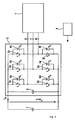
- FIG. 1 is a schematic block diagram of an electrical machine and an inverter with a motor controller according to the invention.
- FIG. 1 shows a schematic representation of a three-phase electric machine 1, which may be designed for example as a synchronous, asynchronous, reluctance or brushless DC machine, with a pulse inverter connected thereto 2.
- the pulse inverter 2 comprises circuit breakers 3a-3f, which with individual phases U, V, W of the electric machine 1 are connected and the phases U, V, W switch either against a high supply voltage potential in the form of a DC link voltage U dcLnk or a low reference potential in the form of ground.
- the switches 3a-3c connected to the intermediate circuit voltage U dcLnk are also referred to as "high-side switches” and the ground-connected switches 3d-3f are referred to as "low-side switches”.
- the pulse inverter 2 further comprises a plurality of freewheeling diodes 4a-4f, which are each arranged parallel to one of the switches 3a-3f.
- the pulse inverter 2 determines the power and operating mode of the electric machine and is controlled by a machine controller 5, which in FIG. 1 is shown only schematically and can also be integrated into the inverter, driven accordingly.
- the electric machine 1 can be operated either in the engine or generator mode.
- the pulse inverter 2 also comprises a so-called intermediate circuit capacitor 6, which essentially serves to stabilize a battery voltage.
- the electrical system of the vehicle with a battery 7 is connected in parallel to the DC link capacitor 6.
- the index "Mdl” indicates here and below that the calculation of the corresponding size is based exclusively on model data
- the rotational speed n can also be calculated from an angular differential (( ⁇ 2- ⁇ 1) / (t2-t1)) of two current vectors measured at time t1 and t2 (
- the measurement of the rotational speed n of the electric machine 1 can be dispensed with.
- this only over a whole electrical revolutions on average can deliver a significant torque when it is controlled synchronously, so that the rotor aligns with the magnetic flux in the stator and thus the current vector. That is, a synchronous machine can only output torque over complete electrical revolutions when the actual rotational speed of the electric machine is synchronous with the angular differential.
- the rotational speed calculated on the basis of the angular differential can be used to check the plausibility of the rotational speed signal of the rotational speed sensor and thus for fault detection for the rotational speed sensor.
- phase currents it is also possible to measure only one or at least only a part of the phase currents and to calculate the other phase currents model-based by utilizing the symmetry properties.
- the described plausibility check and the associated error detection in the current sensor are then not possible.
- stator current components I sA and I sB are calculated in the A and B directions of a stator-fixed reference system - hereinafter referred to as A / B system.
- I sA I sB 1 2 ⁇ 2 3 - 1 3 - 1 3 0 1 3 - 1 3 ⁇ I sU I sV I sW
- stator current components I sd and I sq in the d-direction (longitudinal direction) or q-direction (transverse direction) of a field-oriented one of the stator current components I sA and I sB in the stator-fixed A / B system Reference system - hereinafter referred to as d / q system - are calculated (see equation (6)).
- stator current components I sd and I sq in the d / q system serve as feedback variables in the control of the electrical machine 1.
- I sd I sq cos ⁇ FIx sin ⁇ FIx - sin ⁇ FIx cos ⁇ FIx ⁇ I sA I sB
- the flow angle ⁇ Flx represents the flow angle in the stator-fixed A / B system.
- the duty cycles dyc U , dyc V and dyc W for the individual phases U, V and W can be determined directly.
- the effective stator voltage U sU , U sV and U sW can be reconstructed.
- a current intermediate circuit voltage U dcLnk must additionally be measured.
- current error voltages U sUrr , U sVErr and U sWErr are taken into account, which are advantageously read from a map as a function of the stator currents I sU , I sV and I sW and the intermediate circuit voltage U dcLnk .
- the error voltages U sUrr , U sVErr and U sWErr are due to dead times and non-ideal switching behavior of the circuit breaker 3a-3f.
- an active electrical power Pwr ElMa of the electric machine 1 can be calculated according to equation (11).
- the power loss Pwr ElMaLos of the electric machine according to equation (11) is stored in a characteristic field as a function of the amount I s of the stator current and the rotational speed n.
- Pwr ElMaLos K ⁇ F I s n
- the index "Sens” indicates that no model data is used to calculate the power but only sensor data.
- the plausibility check of the calculated with the help of the machine model electromagnetic torque Trq EmMdl via a power balance The power that generates the electromagnetic torque, on the one hand determined from the machine model according to equation (2) and on the other hand from the sensor data according to equation (13).
- Pwr Err Pwr EmMdl - Pwr Emsens calculated, which is ideally zero and assumes small values in normal operation. If the amount of the thus calculated power error Pwr Err exceeds a predefined parameterizable power threshold value Pwr ErrLim , then the torque calculated on the basis of the machine model is classified as implausible and accordingly an error is detected. Pwr Err > Pwr ErrLim ⁇ error !
- the amount of a maximum effective torque can be determined directly from the amount I s of the stator current.
- the magnitude of the stator current can in turn be determined via the geometric sum of the two orthogonal stator current components in the stator-fixed A / B system according to equation (12).
- the dependence of the amount of the maximum effective torque on the amount of the stator current can advantageously be stored in a characteristic curve and is characteristic for each machine type.
- the set torque corresponds exactly to this maximum value.
- the inverse function can be used for each required setpoint torque Trq EmDes the associated stator current setpoint I sDes be determined.
- I sdes K ⁇ L - 1 Trq Emde
- I sErr I sdes - I s I sErr ⁇ I sErrLim ⁇ Trq em ⁇ Trq Emde I sErr > I sErrLim ⁇ error !
- Trq Em a check of the sign of the effective torque Trq Em. This is done as shown in equation (21) with the aid of the sign of the electromagnetic power Pwr EmSens according to equation (13) and the rotational speed n of the electric machine 1.
- Trq em sgn Pwr Emsens sgn n
Landscapes
- Engineering & Computer Science (AREA)
- Power Engineering (AREA)
- Control Of Ac Motors In General (AREA)
Applications Claiming Priority (2)
| Application Number | Priority Date | Filing Date | Title |
|---|---|---|---|
| DE102009046583A DE102009046583A1 (de) | 2009-11-10 | 2009-11-10 | Verfahren zum Plausibilisieren des Drehmomentes einer elektrischen Maschine und Maschinenregler zur Regelung einer elektrischen Maschine und zur Durchführung des Verfahrens |
| PCT/EP2010/063607 WO2011057838A1 (de) | 2009-11-10 | 2010-09-16 | Verfahren zum plausibilisieren des drehmomentes einer elektrischen maschine und maschinenregler zur regelung einer elektrischen maschine und zur durchführung des verfahrens |
Publications (2)
| Publication Number | Publication Date |
|---|---|
| EP2499737A1 EP2499737A1 (de) | 2012-09-19 |
| EP2499737B1 true EP2499737B1 (de) | 2014-12-10 |
Family
ID=43091771
Family Applications (1)
| Application Number | Title | Priority Date | Filing Date |
|---|---|---|---|
| EP10754508.9A Active EP2499737B1 (de) | 2009-11-10 | 2010-09-16 | Verfahren zum plausibilisieren des drehmomentes einer elektrischen maschine und maschinenregler zur regelung einer elektrischen maschine und zur durchführung des verfahrens |
Country Status (7)
| Country | Link |
|---|---|
| US (1) | US9065376B2 (enExample) |
| EP (1) | EP2499737B1 (enExample) |
| JP (1) | JP5511973B2 (enExample) |
| KR (1) | KR101731663B1 (enExample) |
| CN (1) | CN102598502B (enExample) |
| DE (1) | DE102009046583A1 (enExample) |
| WO (1) | WO2011057838A1 (enExample) |
Families Citing this family (20)
| Publication number | Priority date | Publication date | Assignee | Title |
|---|---|---|---|---|
| EP2540544B1 (de) * | 2011-06-28 | 2014-02-26 | Siemens Aktiengesellschaft | Drehmomentüberwachung bei Fahrzeugen |
| FR2991065B1 (fr) * | 2012-05-23 | 2014-05-02 | Schneider Toshiba Inverter | Systeme de commande securisee d'une charge electrique |
| DE102013204191A1 (de) | 2013-03-12 | 2014-09-18 | Robert Bosch Gmbh | Vorrichtung und Verfahren zum Betreiben eines Kraftfahrzeugs |
| DE102013215306A1 (de) | 2013-08-02 | 2015-02-05 | Robert Bosch Gmbh | Verfahren zum Einschalten und zum Ausschalten einer n-phasigen elektrischen Maschine in einem Kraftfahrzeug |
| US9442029B2 (en) * | 2013-12-27 | 2016-09-13 | Deere & Company | Methods of torque estimation and compensation and systems thereof |
| CN104124907B (zh) * | 2014-07-29 | 2017-10-20 | 长城汽车股份有限公司 | 一种电流传感器故障处理方法及电机控制器 |
| JP6795897B2 (ja) * | 2016-03-14 | 2020-12-02 | Ntn株式会社 | 車輪独立駆動式車両の駆動制御装置 |
| EP3252943A1 (de) * | 2016-06-02 | 2017-12-06 | Trafag AG | Drehmomentregelvorrichtung, elektroantrieb und verfahren zur drehmomentregelung |
| DE202016103713U1 (de) | 2016-07-11 | 2016-08-08 | Ebm-Papst Mulfingen Gmbh & Co. Kg | Überwachung des Betriebszustandes von Synchronmotoren |
| DE102016112693A1 (de) | 2016-07-11 | 2018-01-11 | Ebm-Papst Mulfingen Gmbh & Co. Kg | Überwachung des Betriebszustandes von Synchronmotoren |
| EP3348435A1 (de) * | 2017-01-16 | 2018-07-18 | Siemens Aktiengesellschaft | Verfahren zur überwachung einer elektrischen maschine in einem antriebsstrang eines elektrofahrzeugs sowie nach dem verfahren arbeitende steuerungseinheit |
| EP3348434A1 (de) * | 2017-01-16 | 2018-07-18 | Siemens Aktiengesellschaft | Verfahren zur überwachung eines antriebssystems, insbesondere eines antriebsstrangs eines elektrofahrzeugs, sowie nach dem verfahren arbeitende steuerungseinrichtung |
| DE102017208408A1 (de) * | 2017-05-18 | 2018-11-22 | Zf Friedrichshafen Ag | Überwachung eines Drehmoments einer Drehfeldmaschine |
| DE102017116320A1 (de) * | 2017-07-19 | 2019-01-24 | Valeo Siemens Eautomotive Germany Gmbh | Schaltungsanordnung für eine n-phasige elektrische Maschine, elektrische Maschine für ein Fahrzeug, Fahrzeug und Verfahren zum Betreiben einer n-phasigen elektrischen Maschine |
| DE102017213069A1 (de) * | 2017-07-28 | 2019-01-31 | Robert Bosch Gmbh | Verfahren zur Bestimmung einer Rotorlage einer elektrischen, rotierenden Maschine sowie eine elektrische, rotierende Maschine zur Durchführung eines solchen Verfahrens |
| US11929693B2 (en) * | 2019-12-31 | 2024-03-12 | Mavel edt S.p.A. | Method and system for controlling an electric machine |
| CN113740727B (zh) * | 2020-05-13 | 2022-08-12 | 广东威灵电机制造有限公司 | 电机极对数检测方法、检测装置以及电机控制器 |
| US12202356B2 (en) * | 2022-12-01 | 2025-01-21 | GM Global Technology Operations LLC | Motor degradation identification systems and methods using multiple environmental factors |
| DE102022004576A1 (de) | 2022-12-07 | 2024-06-13 | Mercedes-Benz Group AG | Verfahren zur Berechnung und Überwachung eines Drehmoments einer Drehfeldmaschine |
| CN116520056A (zh) * | 2023-04-28 | 2023-08-01 | 中国第一汽车股份有限公司 | 电机控制器的辐射发射功能的测试方法、装置和车辆 |
Family Cites Families (22)
| Publication number | Priority date | Publication date | Assignee | Title |
|---|---|---|---|---|
| DE3026202A1 (de) * | 1980-07-10 | 1982-02-04 | Siemens AG, 1000 Berlin und 8000 München | Drehfeldmaschinenantrieb mit einer umrichtergespeisten drehfeldmaschine und einer mit zwei wechselspannungsintegratoren und einer rechenmodellschaltung verbundenen umrichtersteuerung |
| DE3034275A1 (de) * | 1980-09-11 | 1982-04-22 | Siemens AG, 1000 Berlin und 8000 München | Vorrichtung zum ermitteln der parameterwerte fuer staenderwiderstand, hauptinduktivitaet und streuinduktivitaet einer asynchronmaschine |
| EP0065722B1 (de) * | 1981-05-25 | 1985-04-03 | Siemens Aktiengesellschaft | Vorrichtung zur Steuerung oder Regelung sowie Modellschaltung einer Schenkelpolmaschine |
| JPS6231385A (ja) * | 1985-07-31 | 1987-02-10 | Yaskawa Electric Mfg Co Ltd | 同期電動機の界磁極位置補正方法 |
| JP2000177610A (ja) * | 1998-12-15 | 2000-06-27 | Toyoda Mach Works Ltd | モータ制御装置 |
| US6803736B1 (en) | 1999-05-19 | 2004-10-12 | Robert Bosch Gmbh | Control system which carries out the model-supported safety monitoring of an electronically regulated controller in the motor vehicle |
| DE10019152A1 (de) * | 1999-05-19 | 2000-12-21 | Bosch Gmbh Robert | Regelungssystem mit modellgestützter Sicherheitsüberwachung eines elektronisch geregelten Stellers im Kraftfahrzeug |
| US6646394B2 (en) * | 2001-07-09 | 2003-11-11 | Nissan Motor Co., Ltd. | Control device for plurality of rotating electrical machines |
| JP3783941B2 (ja) * | 2002-04-25 | 2006-06-07 | 株式会社ジェイテクト | モータ制御装置 |
| GB2404100A (en) * | 2003-07-17 | 2005-01-19 | Bombardier Transp | Model-based monitoring an operation of a converter |
| ITMO20040218A1 (it) * | 2004-08-31 | 2004-11-30 | C A R E R Carrellificio Elettronico | Metodo per il controllo di un motore sincrono a rotare avvolto. |
| DE102005040783A1 (de) | 2005-08-29 | 2007-03-08 | Robert Bosch Gmbh | Verfahren zur Steuerung einer Fahrzeug-Antriebseinheit |
| JP4804100B2 (ja) * | 2005-10-18 | 2011-10-26 | 三洋電機株式会社 | モータ駆動装置及びその制御方法、空気調和装置 |
| DE102006005854A1 (de) * | 2006-02-09 | 2007-08-23 | Robert Bosch Gmbh | Verfahren und Vorrichtung zum Bestimmen des Drehmoments einer elektrischen Maschine |
| JP5024827B2 (ja) | 2006-09-27 | 2012-09-12 | 東芝キヤリア株式会社 | インバータ装置 |
| JP5125216B2 (ja) * | 2007-05-15 | 2013-01-23 | 日本精工株式会社 | 電動パワーステアリング装置 |
| JP5196923B2 (ja) * | 2007-09-07 | 2013-05-15 | 株式会社東芝 | ランドリー機器 |
| EP2040427A1 (en) * | 2007-09-22 | 2009-03-25 | New Day Investment Limited | High speed electrical data transmission system |
| DE102008008536A1 (de) * | 2008-02-11 | 2009-08-13 | Robert Bosch Gmbh | Verfahren für die Steuerung einer elektrischen Maschine und Steuereinrichtung |
| JP2009207315A (ja) | 2008-02-28 | 2009-09-10 | Hitachi Ltd | モータ制御装置 |
| JP4458174B2 (ja) * | 2008-03-21 | 2010-04-28 | 株式会社デンソー | 回転機の制御装置、及び回転機の制御システム |
| ATE556906T1 (de) * | 2009-12-24 | 2012-05-15 | Kanzaki Kokyukoki Mfg Co Ltd | Elektrisches fahrzeug |
-
2009
- 2009-11-10 DE DE102009046583A patent/DE102009046583A1/de not_active Withdrawn
-
2010
- 2010-09-16 KR KR1020127011947A patent/KR101731663B1/ko active Active
- 2010-09-16 CN CN201080050645.6A patent/CN102598502B/zh active Active
- 2010-09-16 WO PCT/EP2010/063607 patent/WO2011057838A1/de not_active Ceased
- 2010-09-16 EP EP10754508.9A patent/EP2499737B1/de active Active
- 2010-09-16 JP JP2012538251A patent/JP5511973B2/ja active Active
- 2010-09-16 US US13/505,591 patent/US9065376B2/en active Active
Also Published As
| Publication number | Publication date |
|---|---|
| DE102009046583A1 (de) | 2011-05-12 |
| WO2011057838A1 (de) | 2011-05-19 |
| US20120278007A1 (en) | 2012-11-01 |
| JP5511973B2 (ja) | 2014-06-04 |
| CN102598502A (zh) | 2012-07-18 |
| CN102598502B (zh) | 2015-02-04 |
| KR20120091194A (ko) | 2012-08-17 |
| JP2013510555A (ja) | 2013-03-21 |
| US9065376B2 (en) | 2015-06-23 |
| EP2499737A1 (de) | 2012-09-19 |
| KR101731663B1 (ko) | 2017-04-28 |
Similar Documents
| Publication | Publication Date | Title |
|---|---|---|
| EP2499737B1 (de) | Verfahren zum plausibilisieren des drehmomentes einer elektrischen maschine und maschinenregler zur regelung einer elektrischen maschine und zur durchführung des verfahrens | |
| DE102010042330B4 (de) | Verfahren und Systeme zum Durchführen von Fehlerdiagnosen für Rotoren von Elektromotoren | |
| DE60036192T2 (de) | Synchronmotor-Steuervorrichtung und Fahrzeug mit der Steuervorrichtung | |
| EP1479157B1 (de) | Verfahren zur fehlererkennung für elektromotoren | |
| EP3017538B1 (de) | Verfahren zur ansteuerung eines mehrphasigen frequenzumrichters zur ansteuerung einer elektromaschine und zugehöriges steuergerät | |
| DE102012212247A1 (de) | Verfahren, Systeme und Vorrichtung zum Steuern eines mehrphasigen Wechselrichters | |
| EP2671090B1 (de) | Verfahren und Vorrichtung zur Erkennung eines Fehlverhaltens einer Elektromaschine | |
| DE102009023372A1 (de) | Elektronische Steuereinrichtung für Fahrzeuge und Lenkungssteuersystem | |
| EP3815237B1 (de) | Verfahren und vorrichtung zur bestimmung einer lage und drehzahl eines rotors einer elektrischen maschine | |
| EP0690556B1 (de) | Stillstandserkennung beim Wiederanlassen eines stromrichtergespeisten Drehstrommotors ohne Drehzahlgeber | |
| DE112018007527T5 (de) | Elektromotor-Steuervorrichtung | |
| DE102016224178A1 (de) | Steuerung einer sechsphasigen PSM | |
| DE102019202464A1 (de) | Verfahren und Steuervorrichtung zum Ermitteln zumindest eines Kennwerts eines Antriebsstrangs, der sich im eingebauten Zustand in einem elektrisch antreibbaren Kraftfahrzeug befindet, sowie Kraftfahrzeug | |
| DE102007021892A1 (de) | Verfahren und Vorrichtung zur Steuerung eines Sternspannungsmodulation verwendenden Elektromotors | |
| EP2540544B1 (de) | Drehmomentüberwachung bei Fahrzeugen | |
| DE102014106716B4 (de) | Steuervorrichtung einer drehenden elektrischen Maschine mit einer Abnormalitätserfassungsfunktion | |
| EP2998753B1 (de) | Überwachungsvorrichtung für eine elektromaschine, steuervorrichtung und verfahren | |
| DE10100565B4 (de) | Verfahren zum Bestimmen eines von einem Asynchronelektromotor aufgebrachten Drehmoments | |
| DE112019001069T5 (de) | Motorregelvorrichtung und Elektrofahrzeug | |
| WO2017190898A1 (de) | Verfahren zur ermittlung der phasenströme einer elektrischen maschine mit einem stromrichter | |
| EP3476038B1 (de) | Verfahren zur regelung einer synchronmaschine und regelvorrichtung für eine synchronmaschine | |
| EP3657670B1 (de) | Verfahren sowie vorrichtung zur fehlersicheren drehzahlüberwachung | |
| DE102012208747A1 (de) | Verfahren zum Betrieb einer Drehfeldmaschine | |
| EP3406027B1 (de) | Vorrichtung und verfahren zum steuern einer elektrischen maschine | |
| EP1746718B1 (de) | Verfahren zur direkten Regelung der Reaktanz einer Drehstrommaschine |
Legal Events
| Date | Code | Title | Description |
|---|---|---|---|
| PUAI | Public reference made under article 153(3) epc to a published international application that has entered the european phase |
Free format text: ORIGINAL CODE: 0009012 |
|
| 17P | Request for examination filed |
Effective date: 20120611 |
|
| AK | Designated contracting states |
Kind code of ref document: A1 Designated state(s): AL AT BE BG CH CY CZ DE DK EE ES FI FR GB GR HR HU IE IS IT LI LT LU LV MC MK MT NL NO PL PT RO SE SI SK SM TR |
|
| DAX | Request for extension of the european patent (deleted) | ||
| REG | Reference to a national code |
Ref country code: DE Ref legal event code: R079 Ref document number: 502010008460 Country of ref document: DE Free format text: PREVIOUS MAIN CLASS: H02P0029020000 Ipc: H02P0021140000 |
|
| GRAP | Despatch of communication of intention to grant a patent |
Free format text: ORIGINAL CODE: EPIDOSNIGR1 |
|
| RIC1 | Information provided on ipc code assigned before grant |
Ipc: H02P 29/02 20060101ALI20140826BHEP Ipc: H02P 21/14 20060101AFI20140826BHEP |
|
| INTG | Intention to grant announced |
Effective date: 20140912 |
|
| GRAS | Grant fee paid |
Free format text: ORIGINAL CODE: EPIDOSNIGR3 |
|
| GRAA | (expected) grant |
Free format text: ORIGINAL CODE: 0009210 |
|
| AK | Designated contracting states |
Kind code of ref document: B1 Designated state(s): AL AT BE BG CH CY CZ DE DK EE ES FI FR GB GR HR HU IE IS IT LI LT LU LV MC MK MT NL NO PL PT RO SE SI SK SM TR |
|
| REG | Reference to a national code |
Ref country code: GB Ref legal event code: FG4D Free format text: NOT ENGLISH |
|
| REG | Reference to a national code |
Ref country code: CH Ref legal event code: EP |
|
| REG | Reference to a national code |
Ref country code: IE Ref legal event code: FG4D Free format text: LANGUAGE OF EP DOCUMENT: GERMAN |
|
| REG | Reference to a national code |
Ref country code: AT Ref legal event code: REF Ref document number: 701094 Country of ref document: AT Kind code of ref document: T Effective date: 20150115 |
|
| REG | Reference to a national code |
Ref country code: DE Ref legal event code: R096 Ref document number: 502010008460 Country of ref document: DE Effective date: 20150122 |
|
| REG | Reference to a national code |
Ref country code: NL Ref legal event code: VDEP Effective date: 20141210 |
|
| REG | Reference to a national code |
Ref country code: NL Ref legal event code: VDEP Effective date: 20141210 |
|
| PG25 | Lapsed in a contracting state [announced via postgrant information from national office to epo] |
Ref country code: ES Free format text: LAPSE BECAUSE OF FAILURE TO SUBMIT A TRANSLATION OF THE DESCRIPTION OR TO PAY THE FEE WITHIN THE PRESCRIBED TIME-LIMIT Effective date: 20141210 Ref country code: FI Free format text: LAPSE BECAUSE OF FAILURE TO SUBMIT A TRANSLATION OF THE DESCRIPTION OR TO PAY THE FEE WITHIN THE PRESCRIBED TIME-LIMIT Effective date: 20141210 Ref country code: LT Free format text: LAPSE BECAUSE OF FAILURE TO SUBMIT A TRANSLATION OF THE DESCRIPTION OR TO PAY THE FEE WITHIN THE PRESCRIBED TIME-LIMIT Effective date: 20141210 Ref country code: NO Free format text: LAPSE BECAUSE OF FAILURE TO SUBMIT A TRANSLATION OF THE DESCRIPTION OR TO PAY THE FEE WITHIN THE PRESCRIBED TIME-LIMIT Effective date: 20150310 |
|
| REG | Reference to a national code |
Ref country code: LT Ref legal event code: MG4D |
|
| PG25 | Lapsed in a contracting state [announced via postgrant information from national office to epo] |
Ref country code: LV Free format text: LAPSE BECAUSE OF FAILURE TO SUBMIT A TRANSLATION OF THE DESCRIPTION OR TO PAY THE FEE WITHIN THE PRESCRIBED TIME-LIMIT Effective date: 20141210 Ref country code: HR Free format text: LAPSE BECAUSE OF FAILURE TO SUBMIT A TRANSLATION OF THE DESCRIPTION OR TO PAY THE FEE WITHIN THE PRESCRIBED TIME-LIMIT Effective date: 20141210 Ref country code: GR Free format text: LAPSE BECAUSE OF FAILURE TO SUBMIT A TRANSLATION OF THE DESCRIPTION OR TO PAY THE FEE WITHIN THE PRESCRIBED TIME-LIMIT Effective date: 20150311 Ref country code: SE Free format text: LAPSE BECAUSE OF FAILURE TO SUBMIT A TRANSLATION OF THE DESCRIPTION OR TO PAY THE FEE WITHIN THE PRESCRIBED TIME-LIMIT Effective date: 20141210 |
|
| PG25 | Lapsed in a contracting state [announced via postgrant information from national office to epo] |
Ref country code: NL Free format text: LAPSE BECAUSE OF FAILURE TO SUBMIT A TRANSLATION OF THE DESCRIPTION OR TO PAY THE FEE WITHIN THE PRESCRIBED TIME-LIMIT Effective date: 20141210 |
|
| PG25 | Lapsed in a contracting state [announced via postgrant information from national office to epo] |
Ref country code: EE Free format text: LAPSE BECAUSE OF FAILURE TO SUBMIT A TRANSLATION OF THE DESCRIPTION OR TO PAY THE FEE WITHIN THE PRESCRIBED TIME-LIMIT Effective date: 20141210 Ref country code: SK Free format text: LAPSE BECAUSE OF FAILURE TO SUBMIT A TRANSLATION OF THE DESCRIPTION OR TO PAY THE FEE WITHIN THE PRESCRIBED TIME-LIMIT Effective date: 20141210 Ref country code: RO Free format text: LAPSE BECAUSE OF FAILURE TO SUBMIT A TRANSLATION OF THE DESCRIPTION OR TO PAY THE FEE WITHIN THE PRESCRIBED TIME-LIMIT Effective date: 20141210 Ref country code: PT Free format text: LAPSE BECAUSE OF FAILURE TO SUBMIT A TRANSLATION OF THE DESCRIPTION OR TO PAY THE FEE WITHIN THE PRESCRIBED TIME-LIMIT Effective date: 20150410 Ref country code: CZ Free format text: LAPSE BECAUSE OF FAILURE TO SUBMIT A TRANSLATION OF THE DESCRIPTION OR TO PAY THE FEE WITHIN THE PRESCRIBED TIME-LIMIT Effective date: 20141210 |
|
| PG25 | Lapsed in a contracting state [announced via postgrant information from national office to epo] |
Ref country code: PL Free format text: LAPSE BECAUSE OF FAILURE TO SUBMIT A TRANSLATION OF THE DESCRIPTION OR TO PAY THE FEE WITHIN THE PRESCRIBED TIME-LIMIT Effective date: 20141210 Ref country code: IS Free format text: LAPSE BECAUSE OF FAILURE TO SUBMIT A TRANSLATION OF THE DESCRIPTION OR TO PAY THE FEE WITHIN THE PRESCRIBED TIME-LIMIT Effective date: 20150410 |
|
| REG | Reference to a national code |
Ref country code: DE Ref legal event code: R097 Ref document number: 502010008460 Country of ref document: DE |
|
| PLBE | No opposition filed within time limit |
Free format text: ORIGINAL CODE: 0009261 |
|
| STAA | Information on the status of an ep patent application or granted ep patent |
Free format text: STATUS: NO OPPOSITION FILED WITHIN TIME LIMIT |
|
| PG25 | Lapsed in a contracting state [announced via postgrant information from national office to epo] |
Ref country code: DK Free format text: LAPSE BECAUSE OF FAILURE TO SUBMIT A TRANSLATION OF THE DESCRIPTION OR TO PAY THE FEE WITHIN THE PRESCRIBED TIME-LIMIT Effective date: 20141210 |
|
| 26N | No opposition filed |
Effective date: 20150911 |
|
| PG25 | Lapsed in a contracting state [announced via postgrant information from national office to epo] |
Ref country code: SI Free format text: LAPSE BECAUSE OF FAILURE TO SUBMIT A TRANSLATION OF THE DESCRIPTION OR TO PAY THE FEE WITHIN THE PRESCRIBED TIME-LIMIT Effective date: 20141210 |
|
| PG25 | Lapsed in a contracting state [announced via postgrant information from national office to epo] |
Ref country code: MC Free format text: LAPSE BECAUSE OF FAILURE TO SUBMIT A TRANSLATION OF THE DESCRIPTION OR TO PAY THE FEE WITHIN THE PRESCRIBED TIME-LIMIT Effective date: 20141210 Ref country code: LU Free format text: LAPSE BECAUSE OF FAILURE TO SUBMIT A TRANSLATION OF THE DESCRIPTION OR TO PAY THE FEE WITHIN THE PRESCRIBED TIME-LIMIT Effective date: 20150916 |
|
| REG | Reference to a national code |
Ref country code: CH Ref legal event code: PL |
|
| REG | Reference to a national code |
Ref country code: IE Ref legal event code: MM4A |
|
| PG25 | Lapsed in a contracting state [announced via postgrant information from national office to epo] |
Ref country code: IE Free format text: LAPSE BECAUSE OF NON-PAYMENT OF DUE FEES Effective date: 20150916 Ref country code: CH Free format text: LAPSE BECAUSE OF NON-PAYMENT OF DUE FEES Effective date: 20150930 Ref country code: LI Free format text: LAPSE BECAUSE OF NON-PAYMENT OF DUE FEES Effective date: 20150930 |
|
| REG | Reference to a national code |
Ref country code: FR Ref legal event code: PLFP Year of fee payment: 7 |
|
| REG | Reference to a national code |
Ref country code: AT Ref legal event code: MM01 Ref document number: 701094 Country of ref document: AT Kind code of ref document: T Effective date: 20150916 |
|
| PG25 | Lapsed in a contracting state [announced via postgrant information from national office to epo] |
Ref country code: AT Free format text: LAPSE BECAUSE OF NON-PAYMENT OF DUE FEES Effective date: 20150916 |
|
| PG25 | Lapsed in a contracting state [announced via postgrant information from national office to epo] |
Ref country code: MT Free format text: LAPSE BECAUSE OF FAILURE TO SUBMIT A TRANSLATION OF THE DESCRIPTION OR TO PAY THE FEE WITHIN THE PRESCRIBED TIME-LIMIT Effective date: 20141210 |
|
| PG25 | Lapsed in a contracting state [announced via postgrant information from national office to epo] |
Ref country code: SM Free format text: LAPSE BECAUSE OF FAILURE TO SUBMIT A TRANSLATION OF THE DESCRIPTION OR TO PAY THE FEE WITHIN THE PRESCRIBED TIME-LIMIT Effective date: 20141210 Ref country code: HU Free format text: LAPSE BECAUSE OF FAILURE TO SUBMIT A TRANSLATION OF THE DESCRIPTION OR TO PAY THE FEE WITHIN THE PRESCRIBED TIME-LIMIT; INVALID AB INITIO Effective date: 20100916 Ref country code: BG Free format text: LAPSE BECAUSE OF FAILURE TO SUBMIT A TRANSLATION OF THE DESCRIPTION OR TO PAY THE FEE WITHIN THE PRESCRIBED TIME-LIMIT Effective date: 20141210 |
|
| PG25 | Lapsed in a contracting state [announced via postgrant information from national office to epo] |
Ref country code: CY Free format text: LAPSE BECAUSE OF FAILURE TO SUBMIT A TRANSLATION OF THE DESCRIPTION OR TO PAY THE FEE WITHIN THE PRESCRIBED TIME-LIMIT Effective date: 20141210 |
|
| PG25 | Lapsed in a contracting state [announced via postgrant information from national office to epo] |
Ref country code: BE Free format text: LAPSE BECAUSE OF NON-PAYMENT OF DUE FEES Effective date: 20150930 |
|
| PG25 | Lapsed in a contracting state [announced via postgrant information from national office to epo] |
Ref country code: TR Free format text: LAPSE BECAUSE OF FAILURE TO SUBMIT A TRANSLATION OF THE DESCRIPTION OR TO PAY THE FEE WITHIN THE PRESCRIBED TIME-LIMIT Effective date: 20141210 |
|
| REG | Reference to a national code |
Ref country code: FR Ref legal event code: PLFP Year of fee payment: 8 |
|
| PG25 | Lapsed in a contracting state [announced via postgrant information from national office to epo] |
Ref country code: MK Free format text: LAPSE BECAUSE OF FAILURE TO SUBMIT A TRANSLATION OF THE DESCRIPTION OR TO PAY THE FEE WITHIN THE PRESCRIBED TIME-LIMIT Effective date: 20141210 |
|
| REG | Reference to a national code |
Ref country code: FR Ref legal event code: PLFP Year of fee payment: 9 |
|
| PG25 | Lapsed in a contracting state [announced via postgrant information from national office to epo] |
Ref country code: AL Free format text: LAPSE BECAUSE OF FAILURE TO SUBMIT A TRANSLATION OF THE DESCRIPTION OR TO PAY THE FEE WITHIN THE PRESCRIBED TIME-LIMIT Effective date: 20141210 |
|
| PGFP | Annual fee paid to national office [announced via postgrant information from national office to epo] |
Ref country code: GB Payment date: 20220927 Year of fee payment: 13 |
|
| PGFP | Annual fee paid to national office [announced via postgrant information from national office to epo] |
Ref country code: IT Payment date: 20220930 Year of fee payment: 13 |
|
| P01 | Opt-out of the competence of the unified patent court (upc) registered |
Effective date: 20230509 |
|
| GBPC | Gb: european patent ceased through non-payment of renewal fee |
Effective date: 20230916 |
|
| PG25 | Lapsed in a contracting state [announced via postgrant information from national office to epo] |
Ref country code: GB Free format text: LAPSE BECAUSE OF NON-PAYMENT OF DUE FEES Effective date: 20230916 |
|
| PG25 | Lapsed in a contracting state [announced via postgrant information from national office to epo] |
Ref country code: GB Free format text: LAPSE BECAUSE OF NON-PAYMENT OF DUE FEES Effective date: 20230916 |
|
| PG25 | Lapsed in a contracting state [announced via postgrant information from national office to epo] |
Ref country code: IT Free format text: LAPSE BECAUSE OF NON-PAYMENT OF DUE FEES Effective date: 20230916 |
|
| PG25 | Lapsed in a contracting state [announced via postgrant information from national office to epo] |
Ref country code: IT Free format text: LAPSE BECAUSE OF NON-PAYMENT OF DUE FEES Effective date: 20230916 |
|
| PGFP | Annual fee paid to national office [announced via postgrant information from national office to epo] |
Ref country code: DE Payment date: 20241126 Year of fee payment: 15 |
|
| PGFP | Annual fee paid to national office [announced via postgrant information from national office to epo] |
Ref country code: FR Payment date: 20250926 Year of fee payment: 16 |