EP2499367B1 - Compresseur muni d'un ensemble soupape - Google Patents
Compresseur muni d'un ensemble soupape Download PDFInfo
- Publication number
- EP2499367B1 EP2499367B1 EP10778629.5A EP10778629A EP2499367B1 EP 2499367 B1 EP2499367 B1 EP 2499367B1 EP 10778629 A EP10778629 A EP 10778629A EP 2499367 B1 EP2499367 B1 EP 2499367B1
- Authority
- EP
- European Patent Office
- Prior art keywords
- valve
- tongue
- cylinder chamber
- cylinder
- compressor according
- Prior art date
- Legal status (The legal status is an assumption and is not a legal conclusion. Google has not performed a legal analysis and makes no representation as to the accuracy of the status listed.)
- Not-in-force
Links
- 238000005452 bending Methods 0.000 claims description 33
- 238000007789 sealing Methods 0.000 claims description 11
- 239000000463 material Substances 0.000 claims description 8
- 238000005057 refrigeration Methods 0.000 claims description 6
- 238000007373 indentation Methods 0.000 claims description 3
- 239000003507 refrigerant Substances 0.000 claims description 3
- 238000003801 milling Methods 0.000 claims description 2
- 239000012530 fluid Substances 0.000 description 5
- 230000006835 compression Effects 0.000 description 3
- 238000007906 compression Methods 0.000 description 3
- 238000005457 optimization Methods 0.000 description 3
- 239000011324 bead Substances 0.000 description 2
- 230000015572 biosynthetic process Effects 0.000 description 2
- 239000007789 gas Substances 0.000 description 2
- 238000004519 manufacturing process Methods 0.000 description 2
- 239000002184 metal Substances 0.000 description 2
- 241000446313 Lamella Species 0.000 description 1
- 238000004026 adhesive bonding Methods 0.000 description 1
- 239000002131 composite material Substances 0.000 description 1
- 238000010276 construction Methods 0.000 description 1
- 238000001816 cooling Methods 0.000 description 1
- 230000001419 dependent effect Effects 0.000 description 1
- 238000004080 punching Methods 0.000 description 1
- 238000005096 rolling process Methods 0.000 description 1
- 238000005476 soldering Methods 0.000 description 1
Images

Classifications
-
- F—MECHANICAL ENGINEERING; LIGHTING; HEATING; WEAPONS; BLASTING
- F04—POSITIVE - DISPLACEMENT MACHINES FOR LIQUIDS; PUMPS FOR LIQUIDS OR ELASTIC FLUIDS
- F04B—POSITIVE-DISPLACEMENT MACHINES FOR LIQUIDS; PUMPS
- F04B39/00—Component parts, details, or accessories, of pumps or pumping systems specially adapted for elastic fluids, not otherwise provided for in, or of interest apart from, groups F04B25/00 - F04B37/00
- F04B39/10—Adaptations or arrangements of distribution members
- F04B39/1073—Adaptations or arrangements of distribution members the members being reed valves
-
- F—MECHANICAL ENGINEERING; LIGHTING; HEATING; WEAPONS; BLASTING
- F04—POSITIVE - DISPLACEMENT MACHINES FOR LIQUIDS; PUMPS FOR LIQUIDS OR ELASTIC FLUIDS
- F04B—POSITIVE-DISPLACEMENT MACHINES FOR LIQUIDS; PUMPS
- F04B39/00—Component parts, details, or accessories, of pumps or pumping systems specially adapted for elastic fluids, not otherwise provided for in, or of interest apart from, groups F04B25/00 - F04B37/00
- F04B39/12—Casings; Cylinders; Cylinder heads; Fluid connections
- F04B39/125—Cylinder heads
Definitions
- the present invention relates to a compressor for the compression of fluids, for example for the compression of refrigerants in household refrigerators.
- Such compressors comprise a cylinder block with a cylinder space in which a piston for generating cylinder positive and negative pressure is arranged to be movable.
- the cylinder chamber is closed by means of a valve system.
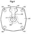
- Fig. 4 shows a cylinder space side view of such a valve system with a valve plate 401, in the corners of which mounting holes 403 are provided for securing the valve plate 401 in a housing.
- the valve plate 401 has a first valve 405 which is shaped as a valve blade and fixedly connected to the valve plate 401 by means of the rivets 407.
- the first valve 405 includes a valve tongue 409 for releasing or closing a first aperture which is in the in Fig. 4 shown position of the valve tongue 409 is covered by this.
- the valve plate 401 further includes a second aperture 411 which is centrally located. At the side facing away from the cylinder chamber of the valve plate 401, a second valve is attached, which closes or releases the second opening 411 in dependence on the pressure conditions prevailing in the cylinder chamber. These are determined by means of an in Fig. 4 Cylinder piston, not shown, generates the circumference 413 in Fig. 4 indicated by dashed lines.
- the publication GB 2 156 046 A shows a refrigerator compressor.
- the refrigerator compressor has a valve plate that includes an inlet port. Inside a cylinder, a valve sheet is arranged, which has a tongue, so that a valve is formed opposite to the inlet opening.
- the tongue has at different locations on a different width and is formed continuously and without recess.
- the patent US 5,173,040 shows an air compressor.
- the air compressor includes a valve plate for covering a cylinder having an inlet and an outlet opening. Inside the cylinder, a V-shaped plate is arranged, which covers the inlet opening from the inside and thus forms a valve.
- the plate is screwed at its ends to the valve plate.
- the movable part of the plate is formed contiguous and without recesses.
- the present invention is based on the recognition that a valve for a compressor can be made more efficient when a valve tongue of the valve along an intra-cylindrical bending edge is flexible.
- the valve can be annular, for example, so that it is inserted as an insert element between the valve plate and the cylinder space. This allows the valve to be manufactured and assembled with a high degree of valve operation reproducibility, high efficiency and reduced dead space, as well as a lower leakage rate.
- the annular valve shape also allows formation of important and required functional openings, such as gas outlets or sensor openings and sensor recesses in the valve plate.
- different valve variants can be used for example for different types of fluid or for different pressures, since no consideration must be taken to a bending edge guide.
- the cylinder space side arranged valve can be provided, for example, to release the breakthrough at cylinder vacuum and close at cylinder overpressure.
- the cylinder chamber extends to the cylinder-side surface of the valve plate, which may optionally be provided with a seal. Due to the arrangement of the valve on the cylinder space side, it can be ensured that the valve tongue is optionally completely arranged and effective together with at least part of the surrounding holding frame in the cylinder space.
- the invention relates to a compressor having a cylinder with a cylinder space open at the end, wherein a valve plate is provided for closing the cylinder space at the front.
- the valve plate comprises an opening to the cylinder chamber and a cylinder chamber side, ie between the cylinder chamber and the valve plate, arranged valve with a valve tongue for closing the opening, wherein a bending edge of the valve tongue extends within the cylinder chamber.
- an axial projection of the bending edge opens in the direction of the cylinder space in this. This ensures that a complex optimization of Bending edge is not necessary, so that different valves for different fluids or pressures can be produced cost-efficiently.
- the valve Due to the cylinder space side arrangement of the valve this is for example intended to release the breakthrough at cylinder vacuum and close at cylinder pressure.
- the cylinder chamber extends to the cylinder-side surface of the valve plate, which may optionally be provided with a seal. Due to the cylinder space side arrangement of the valve can be ensured that the valve tongue is effective in the cylinder chamber.
- the bending edge is determined by a material change, in particular by a perforation or incision or material thickness change, in particular material thickness reduction, or indentation, whereby advantageously an easy determination of the properties of the bending edge is possible.
- the valve tongue is resiliently mounted along the bending edge. This ensures in an advantageous manner that the valve tongue can spring along the bending edge, wherein the valve region outside the bending edge, for example, can be rigidly formed or attached.
- the valve tongue is deflectable at the bending edge.
- the bending edge thus defines a deflection point at which the valve tongue is deflectable.
- the bending edge may be defined for example by a recess or by a notch or by a perforation or by a thinning of material, whereby the deflection of the valve tongue is forced at the bending edge in an advantageous manner.
- the valve tongue is arranged completely within the cylinder space or, for example, attached to the valve plate.
- the valve tongue is effective only within the cylinder chamber. This eliminates the costly consideration of extra-cylindrical valve tongue sections in an optimization of the bending behavior of the valve tongue.
- the valve comprises a holding tongue which at least partially surrounds the valve tongue, on which the valve tongue is resiliently mounted along the bending edge.
- the holding frame surrounds or encloses the valve tongue at least partially or completely, so that the valve can be produced from a workpiece simply by punching out a valve tongue contour.
- the holding frame between the valve plate and an end face of a cylinder wall surrounding the cylinder chamber is arranged.
- the holding frame may be at least partially clamped between the valve plate and the end face of the cylinder wall, whereby a holder of the valve is effected. In this way, the valve can be quickly replaced with another valve, without the need for fixed connections to be solved.
- the valve tongue is a resilient projection of the holding frame, and therefore formed integrally therewith.
- an integral construction of the valve is made possible in an advantageous manner, in which the contours of the valve tongue can be formed by recesses formed in a workpiece.
- the holding frame is at least partially or completely circular or rectangular, which allows a simple formation of the same.
- the valve tongue is preferably within a defined by the support frame circular or rectangular plane.
- the holding frame seals the cylinder space against the valve plate, so that the valve is advantageously used for sealing the cylinder space.
- the holding frame comprises a recess for receiving a positioning elevation, for example a positioning pin, which allows a simple and exact positioning of the valve.
- a positioning elevation for example a positioning pin
- the valve plate comprises a recess arranged at least partially within the cylinder space, in particular a milling, for receiving the valve.
- the valve is annular so that it can be inexpensively manufactured and easily assembled, for example, as an insert valve.
- the valve plate is provided on the cylinder chamber side with a sealing layer which has a recess surrounding the valve or the valve tongue.
- the valve plate comprises a further opening, which can be closed by a further valve, which is arranged on a side facing away from the cylinder space of the valve plate.
- the further valve comprises a valve tongue for closing the further opening and a retaining tongue which at least partially surrounds the valve tongue, the valve tongue being resiliently mounted on the holding frame.
- the further valve may also have further features of the above-mentioned cylinder chamber side valve.
- a compensation ring may be provided for thickness compensation, which surrounds the valve tongue, for example, concentrically.
- the compensation ring has a radius which is greater than a radius of a movable piston in the cylinder chamber, so that it can be guided into the balancing ring, whereby a dead space can be reduced.
- the compensating ring is particularly advantageous when the valve plate is provided with a sealing layer whose thickness is to be compensated.
- the valve tongue comprises an outer edge region, which is provided for closing the opening.
- the valve tongue may have a recess, for example, not to obscure a further breakthrough in the valve plate, which can be closed by a back valve.
- the invention relates to a refrigeration device with the compressor according to the invention for compressing a refrigerant.
- refrigeration device is in particular a household refrigeration appliance understood, ie a refrigerator, which is used for housekeeping in households or in the catering sector, and in particular serves to store food and / or drinks at certain temperatures, such as a refrigerator, a freezer, aharigefrierkombination, a Freezer or a wine fridge.
- valve assembly includes a valve plate 101, in the corners of boreholes 103 are arranged. Further, a valve 105 is provided, which has a holding frame 107 which is circular, for example, and surrounds a valve tongue 109.
- the valve tongue 109 is preferably flexible along a bending edge 110 which extends within the cylinder space. This ensures that the valve tongue 109 can fully spring within the cylinder space.
- the valve tongue 109 is resiliently mounted on the support frame 107 and formed, for example, as a resilient, internal projection of the support frame 107.
- the valve tongue 109 includes an outer edge portion which is for releasing or closing an in Fig. 1 Dashed line 111 is provided in the valve plate 101 is provided.
- the valve plate 101 may have a further opening 115 which, for example, is arranged centrally and may be closable by means of a valve arranged on the valve plate 101 on the rear side. In this case, the valve tongue 109 has a recess 113 so as not to obstruct the further opening 115.
- valve tongue 109 may be connected inside cylinder directly with the valve plate, for example by gluing or by riveting or by soldering.
- valve tongue may also have extra-cylindrical areas.
- the course of the bending edge can be generated or forced, for example, by an inner cylindrical indentation or perforation or material thinning.
- the surfaces of the valve tongue 109 and the holding frame 107 lie in a plane, wherein the holding frame 107 may extend to a circular contour 117.
- a compensation ring 119 may be provided, which surrounds the valve tongue 109 and extends outwardly to the circular contour 117. If the thickness of the valve 105 is less than a thickness of a sealing layer with which the valve plate 101 can be provided, the difference in thickness can be compensated by the aforesaid compensating ring 119, which may have a defined rolling edge.
- the balancing ring 119 can be used either as an elevation on the valve plate 101 or as an elevation on the cylinder.
- the compensation ring 119 preferably has a radius which allows a passage of a piston through the valve tongue 109.
- the seal can be laterally in Fig. 1 have indicated recesses 121, which can lead to a minimization of deformation of the seal at different pressure conditions.
- the valve 105 may, for example, be shaped in the shape of a valve ring and / or have a thickness between 0.15 and 0.25 mm.
- valve plate 101 is provided with a bypass opening 121 and with a Saugzu Genevaö réelle 123.
- the valve plate 101 may further Positioning recesses 125 have, which allow positioning of the valve plate 101 with respect to the cylinder chamber or in a housing of a compressor.
- the valve 105 can be advantageously positioned relative to the valve plate 101 via dowel pins, which can be accommodated in the recesses 128 in the support frame 107 and in the compensation ring 119.
- valve 105 allows due to the internal valve tongue 109 a high reproducibility and efficiency in the cooling capacity, if the compressor containing this compressor is used in a refrigeration device. One reason for this is a small dead space, which allows a reduction of manufacturing and assembly tolerances.
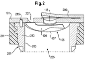
- Fig. 2 shows a section of a compressor with the in Fig. 1 illustrated valve assembly.
- the compressor comprises a cylinder 201 with a cylinder chamber 203, in which a piston 205 is movable.
- the valve plate 101 includes an opening 207, which may correspond to the opening 111 and is closed by means of the valve tongue 109 at cylinder overpressure.
- a further valve 209 is provided on the back, which serves for releasing or closing the further opening 115 and may be shaped, for example, in the form of a lamella.
- the further valve 209 may also be annular and have an outer holding frame, which is provided for holding an inner valve tongue.
- the valve plate 101 may be provided on the back side with a sealing layer 211 whose thickness is greater than the thickness of the valve 105.
- the sealing layer 211 is preferably recessed around the valve 105, resulting in a difference in thickness between a Cylinder space 203 facing surface of the sealing layer and a valve surface can result.
- a compensation ring 213 may be provided, the diameter of which is preferably selected so that the piston 205 can be moved through the compensation ring 213 in the direction of the valve 105.
- a positioning pin 215 may be provided in corresponding seats in the valve plate 101 and in the balance ring 213 or in a cylinder wall.
- a valve edge which may be an outer portion of the holding frame 107 overlaps the cylinder opening and thus serves as a clamping and sealing point.
- the valve edge can also protrude into the interior of the cylinder chamber 203, for example laterally, and form a rigid clamping point for the elastic valve tongue 109, which may be an elastic Lammellenteil. This ensures that the valve tongue 109 can move only in the interior of the cylinder chamber 203. In this case, a spring rate of the valve tongue 109 and the moving mass is consistent with the rigid clamping point.
- different geometries of the valve tongue 109 or of the valve can be used, for example, to release or close more than one passage opening in the valve plate.
- an overpressure is generated for example in the cylinder chamber 203, whereby the valve tongue 109 closes the opening 207.
- the valve tongue 109 acts exclusively in the cylinder chamber 213, because the bending edge extends in the cylinder chamber 213.
- the valve 209 is pushed back, as a result of which the further opening 207 is released, so that a fluid which has reached the cylinder space 203 via the opening 207 at negative pressure is pressed out of the cylinder space 203 again.
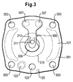
- Fig. 3 shows a cylinder space side view of a valve assembly with a valve plate 301, in the corners of which mounting holes 303 are provided for securing the valve plate 301 in a housing.
- the valve plate 301 has a valve 305, which is formed as a valve blade and fixedly connected to the valve plate 301 by means of the rivets 307.
- the valve 305 includes a valve tongue 309 for releasing or closing a valve first breakthrough, which in the in Fig. 3 shown position of the valve tongue 309 is covered by this.
- the valve plate 301 further includes a second aperture 311 which is centrally located.
- a further valve On the side facing away from the cylinder chamber of the valve plate 301, a further valve is attached, which closes or releases the second opening 311 in dependence on the pressure conditions prevailing in the cylinder chamber.
- the further valve may have the characteristics of the valves 105 and 305.
- valve tongue 309 springs inside the cylinder, it is provided with an inner cylindrical bending edge 313 which extends within the cylinder space circumference 315 indicated by dashed lines.
- the bending edge may, for example, be straight or wavy or curved.
- the valve tongue 309 may be cut to define the course of the bending edge, for example, or have a change in material thickness or a notch or a perforation or lateral recesses. In this way, despite the non-cylindrical attachment of the valve tongue 309 can be ensured that their effective portion due to the inner cylindrical bending edge 313 can cylindrically spring, so that no separate voltage optimization of the bending edge is necessary.
Landscapes
- Engineering & Computer Science (AREA)
- Mechanical Engineering (AREA)
- General Engineering & Computer Science (AREA)
- Compressor (AREA)
Claims (13)
- Compresseur, comprenant un cylindre présentant une chambre de cylindre (203) ouverte sur le côté frontal, une plaque de soupape (101) pour la fermeture de la chambre de cylindre (203) sur le côté frontal, la plaque de soupape (101) étant pourvue d'une ouverture (207) vers la chambre de cylindre (203), et comprenant une soupape (105) située sur le côté de la chambre de cylindre et pourvue d'une lame de soupape (109) pour la fermeture de l'ouverture (207), la lame de soupape (109) présentant une arête de pliage (110) qui s'étend à l'intérieur de la chambre de cylindre (203), et la soupape (105) comprenant un cadre de maintien (107) entourant, au moins en partie, la lame de soupape (109), cadre sur lequel la lame de soupape (109) est montée de manière élastique le long de l'arête de pliage (110), caractérisé en ce que la lame de soupape (109) est pourvue d'un évidement (113).
- Compresseur selon la revendication 1, caractérisé en ce que l'arête de pliage (110) est déterminée par une modification de matériau, notamment par une perforation ou une entaille ou une modification de l'épaisseur de matériau ou une incision.
- Compresseur selon l'une des revendications précédentes, caractérisé en ce que la lame de soupape (109) peut être déviée au niveau de l'arête de pliage (110).
- Compresseur selon l'une des revendications précédentes, caractérisé en ce que la lame de soupape (109) est située ou fixée en totalité à l'intérieur de la chambre de cylindre (203), notamment fixée sur la plaque de soupape (101).
- Compresseur selon l'une des revendications précédentes, caractérisé en ce que le cadre de maintien (107) entoure ou enferme au moins en partie la lame de soupape.
- Compresseur selon l'une des revendications précédentes, caractérisé en ce que le cadre de maintien (107) est situé entre la plaque de soupape (101) et un côté frontal d'une paroi de cylindre entourant la chambre de cylindre (203).
- Compresseur selon l'une des revendications précédentes, caractérisé en ce que le cadre de maintien (107) assure l'étanchéité de la chambre de cylindre (203) vis-à-vis de la plaque de soupape (101).
- Compresseur selon l'une des revendications précédentes, caractérisé en ce que la plaque de soupape (101) est pourvue d'un évidement situé, au moins en partie, à l'intérieur de la chambre de cylindre (203), notamment un fraisage pour recevoir la soupape (105).
- Compresseur selon l'une des revendications précédentes, caractérisé en ce que la soupape (105) est de forme annulaire.
- Compresseur selon l'une des revendications précédentes, caractérisé en ce que la plaque de soupape est pourvue, sur le côté de la chambre de cylindre, d'une couche d'étanchéité (211) qui présente un évidement entourant la soupape (101) ou la lame de soupape (109).
- Compresseur selon l'une des revendications précédentes, caractérisé en ce que la plaque de soupape (101) est pourvue d'une ouverture supplémentaire (115) qui peut être fermée par une autre soupape (209) située sur un côté de la plaque de soupape (101) éloigné de la chambre de cylindre (203).
- Compresseur selon la revendication 11, caractérisé en ce que l'autre soupape (209) comprend une lame de soupape (209) pour la fermeture de l'ouverture supplémentaire (115) et un cadre de maintien entourant, au moins en partie, la lame de soupape (209), la lame de soupape (209) étant montée de manière élastique sur le cadre de maintien.
- Appareil frigorifique, notamment appareil frigorifique domestique, comprenant le compresseur selon l'une des revendications 1 à 12 pour la compression d'un agent frigorifique.
Applications Claiming Priority (2)
| Application Number | Priority Date | Filing Date | Title |
|---|---|---|---|
| DE200910046609 DE102009046609A1 (de) | 2009-11-11 | 2009-11-11 | Verdichter mit einer Ventilanordnung |
| PCT/EP2010/067163 WO2011058028A1 (fr) | 2009-11-11 | 2010-11-10 | Compresseur muni d'un ensemble soupape |
Publications (2)
| Publication Number | Publication Date |
|---|---|
| EP2499367A1 EP2499367A1 (fr) | 2012-09-19 |
| EP2499367B1 true EP2499367B1 (fr) | 2013-10-30 |
Family
ID=43494862
Family Applications (1)
| Application Number | Title | Priority Date | Filing Date |
|---|---|---|---|
| EP10778629.5A Not-in-force EP2499367B1 (fr) | 2009-11-11 | 2010-11-10 | Compresseur muni d'un ensemble soupape |
Country Status (3)
| Country | Link |
|---|---|
| EP (1) | EP2499367B1 (fr) |
| DE (1) | DE102009046609A1 (fr) |
| WO (1) | WO2011058028A1 (fr) |
Families Citing this family (1)
| Publication number | Priority date | Publication date | Assignee | Title |
|---|---|---|---|---|
| CN111677875B (zh) * | 2020-04-22 | 2022-11-15 | 余姚市大隆空压机配件有限公司 | 可调式空压机进气阀 |
Family Cites Families (6)
| Publication number | Priority date | Publication date | Assignee | Title |
|---|---|---|---|---|
| US4642037A (en) * | 1984-03-08 | 1987-02-10 | White Consolidated Industries, Inc. | Reed valve for refrigeration compressor |
| ES1000848Y (es) * | 1986-10-23 | 1988-11-01 | Goenaga Churruca Jose Maria | Dispositivo perfeccionado de valvula de aspiracion para compresores de aire |
| JPH055263Y2 (fr) * | 1990-02-20 | 1993-02-10 | ||
| US6126410A (en) * | 1998-02-12 | 2000-10-03 | Gast Manufacturing Corporation | Head cover assembly for reciprocating compressor |
| DE102004047159B4 (de) * | 2004-09-29 | 2006-09-07 | Danfoss Compressors Gmbh | Kolbenverdichter, insbesondere hermetischer Kältemittelverdichter |
| JP2009509076A (ja) | 2006-09-27 | 2009-03-05 | パナソニック株式会社 | 圧縮機 |
-
2009
- 2009-11-11 DE DE200910046609 patent/DE102009046609A1/de not_active Withdrawn
-
2010
- 2010-11-10 WO PCT/EP2010/067163 patent/WO2011058028A1/fr not_active Ceased
- 2010-11-10 EP EP10778629.5A patent/EP2499367B1/fr not_active Not-in-force
Also Published As
| Publication number | Publication date |
|---|---|
| EP2499367A1 (fr) | 2012-09-19 |
| DE102009046609A1 (de) | 2011-05-12 |
| WO2011058028A1 (fr) | 2011-05-19 |
Similar Documents
| Publication | Publication Date | Title |
|---|---|---|
| DE602004003527T2 (de) | Dämpfereinrichtung für eine Kraftstoffhochdruckpumpe | |
| DE3927589C2 (de) | Dichtungseinheit | |
| DE102008005820A1 (de) | Motor-Pumpenaggregat | |
| EP3482076B1 (fr) | Couvercle de tête de cylindre pour un compresseur de réfrigérant | |
| DE102017007999A1 (de) | Schaltbares Hydrolager | |
| DE202017104280U1 (de) | Ventilkomponentenanordnung und Stellventil mit einer Ventilkomponentenanordnung | |
| DE102004002489A1 (de) | Fluidpumpe, insbesondere Kraftstoff-Hochdruckpumpe | |
| EP4006400B1 (fr) | Dispositif de compensation de pression | |
| DE10230282A1 (de) | Doppelseitig betriebener Kolbenverdichter | |
| DE102014214610B4 (de) | Nockenwellenverstellvorrichtung für eine Brennkraftmaschine | |
| DE102019120730B4 (de) | Zylinderkolben für einen Luftkompressor | |
| DE60317999T2 (de) | Entspannungsventil | |
| EP2499367A1 (fr) | Compresseur muni d'un ensemble soupape | |
| EP4484751A1 (fr) | Compresseur et dispositif de commande d'un débit massique de fluide pour un compresseur | |
| DE202015104151U1 (de) | Stellventil | |
| DE112017006035T5 (de) | Ventilsteuerzeitanpassungsvorrichtung und Verfahren zum Herstellen derselben | |
| DE102009046611A1 (de) | Verdichter | |
| DE112020000261T5 (de) | Metalldämpfer mit Metallmembran und damit versehene Kraftstoffpumpe | |
| DE10148960A1 (de) | Druckbegrenzungsventil | |
| DE102024129639A1 (de) | Vorrichtung zum Steuern eines Fluidmassenstroms für eine Vorrichtung zum Verdichten eines gasförmigen Fluids sowie Vorrichtung zum Verdichten eines gasförmigen Fluids | |
| DE102004005379B3 (de) | Expansionsventil für Kälteanlagen, insbesondere Klimaanlagen in Fahrzeugen | |
| DE102024109919A1 (de) | Vorrichtung zum Steuern eines Fluidmassenstroms für eine Vorrichtung zum Verdichten eines gasförmigen Fluids sowie Vorrichtung zum Verdichten eines gasförmigen Fluids | |
| DE102018125927B4 (de) | Ventilbauteil zum Regeln oder Steuern eines Fluiddrucks | |
| WO2006108767A1 (fr) | Compresseur frigorifique | |
| WO2006103278A1 (fr) | Compresseur de fluide frigorigene |
Legal Events
| Date | Code | Title | Description |
|---|---|---|---|
| PUAI | Public reference made under article 153(3) epc to a published international application that has entered the european phase |
Free format text: ORIGINAL CODE: 0009012 |
|
| 17P | Request for examination filed |
Effective date: 20120611 |
|
| AK | Designated contracting states |
Kind code of ref document: A1 Designated state(s): AL AT BE BG CH CY CZ DE DK EE ES FI FR GB GR HR HU IE IS IT LI LT LU LV MC MK MT NL NO PL PT RO RS SE SI SK SM TR |
|
| DAX | Request for extension of the european patent (deleted) | ||
| GRAP | Despatch of communication of intention to grant a patent |
Free format text: ORIGINAL CODE: EPIDOSNIGR1 |
|
| INTG | Intention to grant announced |
Effective date: 20130711 |
|
| GRAS | Grant fee paid |
Free format text: ORIGINAL CODE: EPIDOSNIGR3 |
|
| GRAA | (expected) grant |
Free format text: ORIGINAL CODE: 0009210 |
|
| AK | Designated contracting states |
Kind code of ref document: B1 Designated state(s): AL AT BE BG CH CY CZ DE DK EE ES FI FR GB GR HR HU IE IS IT LI LT LU LV MC MK MT NL NO PL PT RO RS SE SI SK SM TR |
|
| REG | Reference to a national code |
Ref country code: GB Ref legal event code: FG4D Free format text: NOT ENGLISH |
|
| REG | Reference to a national code |
Ref country code: CH Ref legal event code: EP |
|
| REG | Reference to a national code |
Ref country code: AT Ref legal event code: REF Ref document number: 638570 Country of ref document: AT Kind code of ref document: T Effective date: 20131115 |
|
| REG | Reference to a national code |
Ref country code: IE Ref legal event code: FG4D Free format text: LANGUAGE OF EP DOCUMENT: GERMAN |
|
| REG | Reference to a national code |
Ref country code: DE Ref legal event code: R096 Ref document number: 502010005230 Country of ref document: DE Effective date: 20131224 |
|
| REG | Reference to a national code |
Ref country code: NL Ref legal event code: VDEP Effective date: 20131030 |
|
| REG | Reference to a national code |
Ref country code: LT Ref legal event code: MG4D |
|
| PG25 | Lapsed in a contracting state [announced via postgrant information from national office to epo] |
Ref country code: HR Free format text: LAPSE BECAUSE OF FAILURE TO SUBMIT A TRANSLATION OF THE DESCRIPTION OR TO PAY THE FEE WITHIN THE PRESCRIBED TIME-LIMIT Effective date: 20131030 Ref country code: NO Free format text: LAPSE BECAUSE OF FAILURE TO SUBMIT A TRANSLATION OF THE DESCRIPTION OR TO PAY THE FEE WITHIN THE PRESCRIBED TIME-LIMIT Effective date: 20140130 Ref country code: SE Free format text: LAPSE BECAUSE OF FAILURE TO SUBMIT A TRANSLATION OF THE DESCRIPTION OR TO PAY THE FEE WITHIN THE PRESCRIBED TIME-LIMIT Effective date: 20131030 Ref country code: NL Free format text: LAPSE BECAUSE OF FAILURE TO SUBMIT A TRANSLATION OF THE DESCRIPTION OR TO PAY THE FEE WITHIN THE PRESCRIBED TIME-LIMIT Effective date: 20131030 Ref country code: IS Free format text: LAPSE BECAUSE OF FAILURE TO SUBMIT A TRANSLATION OF THE DESCRIPTION OR TO PAY THE FEE WITHIN THE PRESCRIBED TIME-LIMIT Effective date: 20140228 Ref country code: LT Free format text: LAPSE BECAUSE OF FAILURE TO SUBMIT A TRANSLATION OF THE DESCRIPTION OR TO PAY THE FEE WITHIN THE PRESCRIBED TIME-LIMIT Effective date: 20131030 Ref country code: FI Free format text: LAPSE BECAUSE OF FAILURE TO SUBMIT A TRANSLATION OF THE DESCRIPTION OR TO PAY THE FEE WITHIN THE PRESCRIBED TIME-LIMIT Effective date: 20131030 |
|
| PG25 | Lapsed in a contracting state [announced via postgrant information from national office to epo] |
Ref country code: RS Free format text: LAPSE BECAUSE OF FAILURE TO SUBMIT A TRANSLATION OF THE DESCRIPTION OR TO PAY THE FEE WITHIN THE PRESCRIBED TIME-LIMIT Effective date: 20131030 Ref country code: CY Free format text: LAPSE BECAUSE OF FAILURE TO SUBMIT A TRANSLATION OF THE DESCRIPTION OR TO PAY THE FEE WITHIN THE PRESCRIBED TIME-LIMIT Effective date: 20131030 Ref country code: LV Free format text: LAPSE BECAUSE OF FAILURE TO SUBMIT A TRANSLATION OF THE DESCRIPTION OR TO PAY THE FEE WITHIN THE PRESCRIBED TIME-LIMIT Effective date: 20131030 Ref country code: ES Free format text: LAPSE BECAUSE OF FAILURE TO SUBMIT A TRANSLATION OF THE DESCRIPTION OR TO PAY THE FEE WITHIN THE PRESCRIBED TIME-LIMIT Effective date: 20131030 |
|
| BERE | Be: lapsed |
Owner name: BSH BOSCH UND SIEMENS HAUSGERATE G.M.B.H. Effective date: 20131130 |
|
| PG25 | Lapsed in a contracting state [announced via postgrant information from national office to epo] |
Ref country code: PT Free format text: LAPSE BECAUSE OF FAILURE TO SUBMIT A TRANSLATION OF THE DESCRIPTION OR TO PAY THE FEE WITHIN THE PRESCRIBED TIME-LIMIT Effective date: 20140228 |
|
| PG25 | Lapsed in a contracting state [announced via postgrant information from national office to epo] |
Ref country code: MC Free format text: LAPSE BECAUSE OF FAILURE TO SUBMIT A TRANSLATION OF THE DESCRIPTION OR TO PAY THE FEE WITHIN THE PRESCRIBED TIME-LIMIT Effective date: 20131030 Ref country code: EE Free format text: LAPSE BECAUSE OF FAILURE TO SUBMIT A TRANSLATION OF THE DESCRIPTION OR TO PAY THE FEE WITHIN THE PRESCRIBED TIME-LIMIT Effective date: 20131030 |
|
| REG | Reference to a national code |
Ref country code: DE Ref legal event code: R097 Ref document number: 502010005230 Country of ref document: DE |
|
| REG | Reference to a national code |
Ref country code: IE Ref legal event code: MM4A |
|
| PG25 | Lapsed in a contracting state [announced via postgrant information from national office to epo] |
Ref country code: CZ Free format text: LAPSE BECAUSE OF FAILURE TO SUBMIT A TRANSLATION OF THE DESCRIPTION OR TO PAY THE FEE WITHIN THE PRESCRIBED TIME-LIMIT Effective date: 20131030 Ref country code: IT Free format text: LAPSE BECAUSE OF FAILURE TO SUBMIT A TRANSLATION OF THE DESCRIPTION OR TO PAY THE FEE WITHIN THE PRESCRIBED TIME-LIMIT Effective date: 20131030 Ref country code: RO Free format text: LAPSE BECAUSE OF FAILURE TO SUBMIT A TRANSLATION OF THE DESCRIPTION OR TO PAY THE FEE WITHIN THE PRESCRIBED TIME-LIMIT Effective date: 20131030 Ref country code: PL Free format text: LAPSE BECAUSE OF FAILURE TO SUBMIT A TRANSLATION OF THE DESCRIPTION OR TO PAY THE FEE WITHIN THE PRESCRIBED TIME-LIMIT Effective date: 20131030 Ref country code: SK Free format text: LAPSE BECAUSE OF FAILURE TO SUBMIT A TRANSLATION OF THE DESCRIPTION OR TO PAY THE FEE WITHIN THE PRESCRIBED TIME-LIMIT Effective date: 20131030 |
|
| PLBE | No opposition filed within time limit |
Free format text: ORIGINAL CODE: 0009261 |
|
| STAA | Information on the status of an ep patent application or granted ep patent |
Free format text: STATUS: NO OPPOSITION FILED WITHIN TIME LIMIT |
|
| PG25 | Lapsed in a contracting state [announced via postgrant information from national office to epo] |
Ref country code: BE Free format text: LAPSE BECAUSE OF NON-PAYMENT OF DUE FEES Effective date: 20131130 Ref country code: DK Free format text: LAPSE BECAUSE OF FAILURE TO SUBMIT A TRANSLATION OF THE DESCRIPTION OR TO PAY THE FEE WITHIN THE PRESCRIBED TIME-LIMIT Effective date: 20131030 |
|
| 26N | No opposition filed |
Effective date: 20140731 |
|
| REG | Reference to a national code |
Ref country code: FR Ref legal event code: ST Effective date: 20140922 |
|
| PG25 | Lapsed in a contracting state [announced via postgrant information from national office to epo] |
Ref country code: IE Free format text: LAPSE BECAUSE OF NON-PAYMENT OF DUE FEES Effective date: 20131110 |
|
| REG | Reference to a national code |
Ref country code: DE Ref legal event code: R097 Ref document number: 502010005230 Country of ref document: DE Effective date: 20140731 |
|
| PG25 | Lapsed in a contracting state [announced via postgrant information from national office to epo] |
Ref country code: FR Free format text: LAPSE BECAUSE OF NON-PAYMENT OF DUE FEES Effective date: 20131230 |
|
| PGFP | Annual fee paid to national office [announced via postgrant information from national office to epo] |
Ref country code: DE Payment date: 20141130 Year of fee payment: 5 |
|
| PG25 | Lapsed in a contracting state [announced via postgrant information from national office to epo] |
Ref country code: SI Free format text: LAPSE BECAUSE OF FAILURE TO SUBMIT A TRANSLATION OF THE DESCRIPTION OR TO PAY THE FEE WITHIN THE PRESCRIBED TIME-LIMIT Effective date: 20131030 |
|
| REG | Reference to a national code |
Ref country code: CH Ref legal event code: PFA Owner name: BSH HAUSGERAETE GMBH, DE Free format text: FORMER OWNER: BSH BOSCH UND SIEMENS HAUSGERAETE GMBH, DE |
|
| REG | Reference to a national code |
Ref country code: DE Ref legal event code: R081 Ref document number: 502010005230 Country of ref document: DE Owner name: BSH HAUSGERAETE GMBH, DE Free format text: FORMER OWNER: BSH BOSCH UND SIEMENS HAUSGERAETE GMBH, 81739 MUENCHEN, DE Effective date: 20150409 |
|
| PG25 | Lapsed in a contracting state [announced via postgrant information from national office to epo] |
Ref country code: SM Free format text: LAPSE BECAUSE OF FAILURE TO SUBMIT A TRANSLATION OF THE DESCRIPTION OR TO PAY THE FEE WITHIN THE PRESCRIBED TIME-LIMIT Effective date: 20131030 |
|
| REG | Reference to a national code |
Ref country code: CH Ref legal event code: PL |
|
| GBPC | Gb: european patent ceased through non-payment of renewal fee |
Effective date: 20141110 |
|
| PG25 | Lapsed in a contracting state [announced via postgrant information from national office to epo] |
Ref country code: MK Free format text: LAPSE BECAUSE OF FAILURE TO SUBMIT A TRANSLATION OF THE DESCRIPTION OR TO PAY THE FEE WITHIN THE PRESCRIBED TIME-LIMIT Effective date: 20131030 Ref country code: LU Free format text: LAPSE BECAUSE OF NON-PAYMENT OF DUE FEES Effective date: 20131110 Ref country code: HU Free format text: LAPSE BECAUSE OF FAILURE TO SUBMIT A TRANSLATION OF THE DESCRIPTION OR TO PAY THE FEE WITHIN THE PRESCRIBED TIME-LIMIT; INVALID AB INITIO Effective date: 20101110 Ref country code: CH Free format text: LAPSE BECAUSE OF NON-PAYMENT OF DUE FEES Effective date: 20141130 Ref country code: LI Free format text: LAPSE BECAUSE OF NON-PAYMENT OF DUE FEES Effective date: 20141130 Ref country code: BG Free format text: LAPSE BECAUSE OF FAILURE TO SUBMIT A TRANSLATION OF THE DESCRIPTION OR TO PAY THE FEE WITHIN THE PRESCRIBED TIME-LIMIT Effective date: 20131030 |
|
| PG25 | Lapsed in a contracting state [announced via postgrant information from national office to epo] |
Ref country code: MT Free format text: LAPSE BECAUSE OF FAILURE TO SUBMIT A TRANSLATION OF THE DESCRIPTION OR TO PAY THE FEE WITHIN THE PRESCRIBED TIME-LIMIT Effective date: 20131030 Ref country code: GR Free format text: LAPSE BECAUSE OF NON-PAYMENT OF DUE FEES Effective date: 20131030 |
|
| PG25 | Lapsed in a contracting state [announced via postgrant information from national office to epo] |
Ref country code: GB Free format text: LAPSE BECAUSE OF NON-PAYMENT OF DUE FEES Effective date: 20141110 |
|
| REG | Reference to a national code |
Ref country code: DE Ref legal event code: R119 Ref document number: 502010005230 Country of ref document: DE |
|
| PG25 | Lapsed in a contracting state [announced via postgrant information from national office to epo] |
Ref country code: GR Free format text: LAPSE BECAUSE OF FAILURE TO SUBMIT A TRANSLATION OF THE DESCRIPTION OR TO PAY THE FEE WITHIN THE PRESCRIBED TIME-LIMIT Effective date: 20140131 |
|
| PG25 | Lapsed in a contracting state [announced via postgrant information from national office to epo] |
Ref country code: TR Free format text: LAPSE BECAUSE OF FAILURE TO SUBMIT A TRANSLATION OF THE DESCRIPTION OR TO PAY THE FEE WITHIN THE PRESCRIBED TIME-LIMIT Effective date: 20131030 |
|
| PG25 | Lapsed in a contracting state [announced via postgrant information from national office to epo] |
Ref country code: DE Free format text: LAPSE BECAUSE OF NON-PAYMENT OF DUE FEES Effective date: 20160601 |
|
| REG | Reference to a national code |
Ref country code: AT Ref legal event code: MM01 Ref document number: 638570 Country of ref document: AT Kind code of ref document: T Effective date: 20151110 |
|
| PG25 | Lapsed in a contracting state [announced via postgrant information from national office to epo] |
Ref country code: AT Free format text: LAPSE BECAUSE OF NON-PAYMENT OF DUE FEES Effective date: 20151110 |
|
| PG25 | Lapsed in a contracting state [announced via postgrant information from national office to epo] |
Ref country code: AL Free format text: LAPSE BECAUSE OF FAILURE TO SUBMIT A TRANSLATION OF THE DESCRIPTION OR TO PAY THE FEE WITHIN THE PRESCRIBED TIME-LIMIT Effective date: 20131030 |