EP2499367B1 - Verdichter mit einer ventilanordnung - Google Patents
Verdichter mit einer ventilanordnung Download PDFInfo
- Publication number
- EP2499367B1 EP2499367B1 EP10778629.5A EP10778629A EP2499367B1 EP 2499367 B1 EP2499367 B1 EP 2499367B1 EP 10778629 A EP10778629 A EP 10778629A EP 2499367 B1 EP2499367 B1 EP 2499367B1
- Authority
- EP
- European Patent Office
- Prior art keywords
- valve
- tongue
- cylinder chamber
- cylinder
- compressor according
- Prior art date
- Legal status (The legal status is an assumption and is not a legal conclusion. Google has not performed a legal analysis and makes no representation as to the accuracy of the status listed.)
- Not-in-force
Links
- 238000005452 bending Methods 0.000 claims description 33
- 238000007789 sealing Methods 0.000 claims description 11
- 239000000463 material Substances 0.000 claims description 8
- 238000005057 refrigeration Methods 0.000 claims description 6
- 238000007373 indentation Methods 0.000 claims description 3
- 239000003507 refrigerant Substances 0.000 claims description 3
- 238000003801 milling Methods 0.000 claims description 2
- 239000012530 fluid Substances 0.000 description 5
- 230000006835 compression Effects 0.000 description 3
- 238000007906 compression Methods 0.000 description 3
- 238000005457 optimization Methods 0.000 description 3
- 239000011324 bead Substances 0.000 description 2
- 230000015572 biosynthetic process Effects 0.000 description 2
- 239000007789 gas Substances 0.000 description 2
- 238000004519 manufacturing process Methods 0.000 description 2
- 239000002184 metal Substances 0.000 description 2
- 241000446313 Lamella Species 0.000 description 1
- 238000004026 adhesive bonding Methods 0.000 description 1
- 239000002131 composite material Substances 0.000 description 1
- 238000010276 construction Methods 0.000 description 1
- 238000001816 cooling Methods 0.000 description 1
- 230000001419 dependent effect Effects 0.000 description 1
- 238000004080 punching Methods 0.000 description 1
- 238000005096 rolling process Methods 0.000 description 1
- 238000005476 soldering Methods 0.000 description 1
Images

Classifications
-
- F—MECHANICAL ENGINEERING; LIGHTING; HEATING; WEAPONS; BLASTING
- F04—POSITIVE - DISPLACEMENT MACHINES FOR LIQUIDS; PUMPS FOR LIQUIDS OR ELASTIC FLUIDS
- F04B—POSITIVE-DISPLACEMENT MACHINES FOR LIQUIDS; PUMPS
- F04B39/00—Component parts, details, or accessories, of pumps or pumping systems specially adapted for elastic fluids, not otherwise provided for in, or of interest apart from, groups F04B25/00 - F04B37/00
- F04B39/10—Adaptations or arrangements of distribution members
- F04B39/1073—Adaptations or arrangements of distribution members the members being reed valves
-
- F—MECHANICAL ENGINEERING; LIGHTING; HEATING; WEAPONS; BLASTING
- F04—POSITIVE - DISPLACEMENT MACHINES FOR LIQUIDS; PUMPS FOR LIQUIDS OR ELASTIC FLUIDS
- F04B—POSITIVE-DISPLACEMENT MACHINES FOR LIQUIDS; PUMPS
- F04B39/00—Component parts, details, or accessories, of pumps or pumping systems specially adapted for elastic fluids, not otherwise provided for in, or of interest apart from, groups F04B25/00 - F04B37/00
- F04B39/12—Casings; Cylinders; Cylinder heads; Fluid connections
- F04B39/125—Cylinder heads
Definitions
- the present invention relates to a compressor for the compression of fluids, for example for the compression of refrigerants in household refrigerators.
- Such compressors comprise a cylinder block with a cylinder space in which a piston for generating cylinder positive and negative pressure is arranged to be movable.
- the cylinder chamber is closed by means of a valve system.
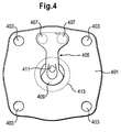
- Fig. 4 shows a cylinder space side view of such a valve system with a valve plate 401, in the corners of which mounting holes 403 are provided for securing the valve plate 401 in a housing.
- the valve plate 401 has a first valve 405 which is shaped as a valve blade and fixedly connected to the valve plate 401 by means of the rivets 407.
- the first valve 405 includes a valve tongue 409 for releasing or closing a first aperture which is in the in Fig. 4 shown position of the valve tongue 409 is covered by this.
- the valve plate 401 further includes a second aperture 411 which is centrally located. At the side facing away from the cylinder chamber of the valve plate 401, a second valve is attached, which closes or releases the second opening 411 in dependence on the pressure conditions prevailing in the cylinder chamber. These are determined by means of an in Fig. 4 Cylinder piston, not shown, generates the circumference 413 in Fig. 4 indicated by dashed lines.
- the publication GB 2 156 046 A shows a refrigerator compressor.
- the refrigerator compressor has a valve plate that includes an inlet port. Inside a cylinder, a valve sheet is arranged, which has a tongue, so that a valve is formed opposite to the inlet opening.
- the tongue has at different locations on a different width and is formed continuously and without recess.
- the patent US 5,173,040 shows an air compressor.
- the air compressor includes a valve plate for covering a cylinder having an inlet and an outlet opening. Inside the cylinder, a V-shaped plate is arranged, which covers the inlet opening from the inside and thus forms a valve.
- the plate is screwed at its ends to the valve plate.
- the movable part of the plate is formed contiguous and without recesses.
- the present invention is based on the recognition that a valve for a compressor can be made more efficient when a valve tongue of the valve along an intra-cylindrical bending edge is flexible.
- the valve can be annular, for example, so that it is inserted as an insert element between the valve plate and the cylinder space. This allows the valve to be manufactured and assembled with a high degree of valve operation reproducibility, high efficiency and reduced dead space, as well as a lower leakage rate.
- the annular valve shape also allows formation of important and required functional openings, such as gas outlets or sensor openings and sensor recesses in the valve plate.
- different valve variants can be used for example for different types of fluid or for different pressures, since no consideration must be taken to a bending edge guide.
- the cylinder space side arranged valve can be provided, for example, to release the breakthrough at cylinder vacuum and close at cylinder overpressure.
- the cylinder chamber extends to the cylinder-side surface of the valve plate, which may optionally be provided with a seal. Due to the arrangement of the valve on the cylinder space side, it can be ensured that the valve tongue is optionally completely arranged and effective together with at least part of the surrounding holding frame in the cylinder space.
- the invention relates to a compressor having a cylinder with a cylinder space open at the end, wherein a valve plate is provided for closing the cylinder space at the front.
- the valve plate comprises an opening to the cylinder chamber and a cylinder chamber side, ie between the cylinder chamber and the valve plate, arranged valve with a valve tongue for closing the opening, wherein a bending edge of the valve tongue extends within the cylinder chamber.
- an axial projection of the bending edge opens in the direction of the cylinder space in this. This ensures that a complex optimization of Bending edge is not necessary, so that different valves for different fluids or pressures can be produced cost-efficiently.
- the valve Due to the cylinder space side arrangement of the valve this is for example intended to release the breakthrough at cylinder vacuum and close at cylinder pressure.
- the cylinder chamber extends to the cylinder-side surface of the valve plate, which may optionally be provided with a seal. Due to the cylinder space side arrangement of the valve can be ensured that the valve tongue is effective in the cylinder chamber.
- the bending edge is determined by a material change, in particular by a perforation or incision or material thickness change, in particular material thickness reduction, or indentation, whereby advantageously an easy determination of the properties of the bending edge is possible.
- the valve tongue is resiliently mounted along the bending edge. This ensures in an advantageous manner that the valve tongue can spring along the bending edge, wherein the valve region outside the bending edge, for example, can be rigidly formed or attached.
- the valve tongue is deflectable at the bending edge.
- the bending edge thus defines a deflection point at which the valve tongue is deflectable.
- the bending edge may be defined for example by a recess or by a notch or by a perforation or by a thinning of material, whereby the deflection of the valve tongue is forced at the bending edge in an advantageous manner.
- the valve tongue is arranged completely within the cylinder space or, for example, attached to the valve plate.
- the valve tongue is effective only within the cylinder chamber. This eliminates the costly consideration of extra-cylindrical valve tongue sections in an optimization of the bending behavior of the valve tongue.
- the valve comprises a holding tongue which at least partially surrounds the valve tongue, on which the valve tongue is resiliently mounted along the bending edge.
- the holding frame surrounds or encloses the valve tongue at least partially or completely, so that the valve can be produced from a workpiece simply by punching out a valve tongue contour.
- the holding frame between the valve plate and an end face of a cylinder wall surrounding the cylinder chamber is arranged.
- the holding frame may be at least partially clamped between the valve plate and the end face of the cylinder wall, whereby a holder of the valve is effected. In this way, the valve can be quickly replaced with another valve, without the need for fixed connections to be solved.
- the valve tongue is a resilient projection of the holding frame, and therefore formed integrally therewith.
- an integral construction of the valve is made possible in an advantageous manner, in which the contours of the valve tongue can be formed by recesses formed in a workpiece.
- the holding frame is at least partially or completely circular or rectangular, which allows a simple formation of the same.
- the valve tongue is preferably within a defined by the support frame circular or rectangular plane.
- the holding frame seals the cylinder space against the valve plate, so that the valve is advantageously used for sealing the cylinder space.
- the holding frame comprises a recess for receiving a positioning elevation, for example a positioning pin, which allows a simple and exact positioning of the valve.
- a positioning elevation for example a positioning pin
- the valve plate comprises a recess arranged at least partially within the cylinder space, in particular a milling, for receiving the valve.
- the valve is annular so that it can be inexpensively manufactured and easily assembled, for example, as an insert valve.
- the valve plate is provided on the cylinder chamber side with a sealing layer which has a recess surrounding the valve or the valve tongue.
- the valve plate comprises a further opening, which can be closed by a further valve, which is arranged on a side facing away from the cylinder space of the valve plate.
- the further valve comprises a valve tongue for closing the further opening and a retaining tongue which at least partially surrounds the valve tongue, the valve tongue being resiliently mounted on the holding frame.
- the further valve may also have further features of the above-mentioned cylinder chamber side valve.
- a compensation ring may be provided for thickness compensation, which surrounds the valve tongue, for example, concentrically.
- the compensation ring has a radius which is greater than a radius of a movable piston in the cylinder chamber, so that it can be guided into the balancing ring, whereby a dead space can be reduced.
- the compensating ring is particularly advantageous when the valve plate is provided with a sealing layer whose thickness is to be compensated.
- the valve tongue comprises an outer edge region, which is provided for closing the opening.
- the valve tongue may have a recess, for example, not to obscure a further breakthrough in the valve plate, which can be closed by a back valve.
- the invention relates to a refrigeration device with the compressor according to the invention for compressing a refrigerant.
- refrigeration device is in particular a household refrigeration appliance understood, ie a refrigerator, which is used for housekeeping in households or in the catering sector, and in particular serves to store food and / or drinks at certain temperatures, such as a refrigerator, a freezer, aharigefrierkombination, a Freezer or a wine fridge.
- valve assembly includes a valve plate 101, in the corners of boreholes 103 are arranged. Further, a valve 105 is provided, which has a holding frame 107 which is circular, for example, and surrounds a valve tongue 109.
- the valve tongue 109 is preferably flexible along a bending edge 110 which extends within the cylinder space. This ensures that the valve tongue 109 can fully spring within the cylinder space.
- the valve tongue 109 is resiliently mounted on the support frame 107 and formed, for example, as a resilient, internal projection of the support frame 107.
- the valve tongue 109 includes an outer edge portion which is for releasing or closing an in Fig. 1 Dashed line 111 is provided in the valve plate 101 is provided.
- the valve plate 101 may have a further opening 115 which, for example, is arranged centrally and may be closable by means of a valve arranged on the valve plate 101 on the rear side. In this case, the valve tongue 109 has a recess 113 so as not to obstruct the further opening 115.
- valve tongue 109 may be connected inside cylinder directly with the valve plate, for example by gluing or by riveting or by soldering.
- valve tongue may also have extra-cylindrical areas.
- the course of the bending edge can be generated or forced, for example, by an inner cylindrical indentation or perforation or material thinning.
- the surfaces of the valve tongue 109 and the holding frame 107 lie in a plane, wherein the holding frame 107 may extend to a circular contour 117.
- a compensation ring 119 may be provided, which surrounds the valve tongue 109 and extends outwardly to the circular contour 117. If the thickness of the valve 105 is less than a thickness of a sealing layer with which the valve plate 101 can be provided, the difference in thickness can be compensated by the aforesaid compensating ring 119, which may have a defined rolling edge.
- the balancing ring 119 can be used either as an elevation on the valve plate 101 or as an elevation on the cylinder.
- the compensation ring 119 preferably has a radius which allows a passage of a piston through the valve tongue 109.
- the seal can be laterally in Fig. 1 have indicated recesses 121, which can lead to a minimization of deformation of the seal at different pressure conditions.
- the valve 105 may, for example, be shaped in the shape of a valve ring and / or have a thickness between 0.15 and 0.25 mm.
- valve plate 101 is provided with a bypass opening 121 and with a Saugzu Genevaö réelle 123.
- the valve plate 101 may further Positioning recesses 125 have, which allow positioning of the valve plate 101 with respect to the cylinder chamber or in a housing of a compressor.
- the valve 105 can be advantageously positioned relative to the valve plate 101 via dowel pins, which can be accommodated in the recesses 128 in the support frame 107 and in the compensation ring 119.
- valve 105 allows due to the internal valve tongue 109 a high reproducibility and efficiency in the cooling capacity, if the compressor containing this compressor is used in a refrigeration device. One reason for this is a small dead space, which allows a reduction of manufacturing and assembly tolerances.
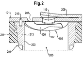
- Fig. 2 shows a section of a compressor with the in Fig. 1 illustrated valve assembly.
- the compressor comprises a cylinder 201 with a cylinder chamber 203, in which a piston 205 is movable.
- the valve plate 101 includes an opening 207, which may correspond to the opening 111 and is closed by means of the valve tongue 109 at cylinder overpressure.
- a further valve 209 is provided on the back, which serves for releasing or closing the further opening 115 and may be shaped, for example, in the form of a lamella.
- the further valve 209 may also be annular and have an outer holding frame, which is provided for holding an inner valve tongue.
- the valve plate 101 may be provided on the back side with a sealing layer 211 whose thickness is greater than the thickness of the valve 105.
- the sealing layer 211 is preferably recessed around the valve 105, resulting in a difference in thickness between a Cylinder space 203 facing surface of the sealing layer and a valve surface can result.
- a compensation ring 213 may be provided, the diameter of which is preferably selected so that the piston 205 can be moved through the compensation ring 213 in the direction of the valve 105.
- a positioning pin 215 may be provided in corresponding seats in the valve plate 101 and in the balance ring 213 or in a cylinder wall.
- a valve edge which may be an outer portion of the holding frame 107 overlaps the cylinder opening and thus serves as a clamping and sealing point.
- the valve edge can also protrude into the interior of the cylinder chamber 203, for example laterally, and form a rigid clamping point for the elastic valve tongue 109, which may be an elastic Lammellenteil. This ensures that the valve tongue 109 can move only in the interior of the cylinder chamber 203. In this case, a spring rate of the valve tongue 109 and the moving mass is consistent with the rigid clamping point.
- different geometries of the valve tongue 109 or of the valve can be used, for example, to release or close more than one passage opening in the valve plate.
- an overpressure is generated for example in the cylinder chamber 203, whereby the valve tongue 109 closes the opening 207.
- the valve tongue 109 acts exclusively in the cylinder chamber 213, because the bending edge extends in the cylinder chamber 213.
- the valve 209 is pushed back, as a result of which the further opening 207 is released, so that a fluid which has reached the cylinder space 203 via the opening 207 at negative pressure is pressed out of the cylinder space 203 again.
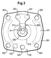
- Fig. 3 shows a cylinder space side view of a valve assembly with a valve plate 301, in the corners of which mounting holes 303 are provided for securing the valve plate 301 in a housing.
- the valve plate 301 has a valve 305, which is formed as a valve blade and fixedly connected to the valve plate 301 by means of the rivets 307.
- the valve 305 includes a valve tongue 309 for releasing or closing a valve first breakthrough, which in the in Fig. 3 shown position of the valve tongue 309 is covered by this.
- the valve plate 301 further includes a second aperture 311 which is centrally located.
- a further valve On the side facing away from the cylinder chamber of the valve plate 301, a further valve is attached, which closes or releases the second opening 311 in dependence on the pressure conditions prevailing in the cylinder chamber.
- the further valve may have the characteristics of the valves 105 and 305.
- valve tongue 309 springs inside the cylinder, it is provided with an inner cylindrical bending edge 313 which extends within the cylinder space circumference 315 indicated by dashed lines.
- the bending edge may, for example, be straight or wavy or curved.
- the valve tongue 309 may be cut to define the course of the bending edge, for example, or have a change in material thickness or a notch or a perforation or lateral recesses. In this way, despite the non-cylindrical attachment of the valve tongue 309 can be ensured that their effective portion due to the inner cylindrical bending edge 313 can cylindrically spring, so that no separate voltage optimization of the bending edge is necessary.
Landscapes
- Engineering & Computer Science (AREA)
- Mechanical Engineering (AREA)
- General Engineering & Computer Science (AREA)
- Compressor (AREA)
Description
- Die vorliegende Erfindung betrifft einen Verdichter zur Verdichtung von Fluiden, beispielsweise zur Verdichtung von Kältemitteln in Haushaltskältegeräten.
- Zur Verdichtung von Fluiden wie beispielsweise Gasen werden üblicherweise Verdichter eingesetzt, wie sie in der Druckschrift
WO 2008/047515 A1 beschrieben sind. Derartige Verdichter umfassen einen Zylinderblock mit einem Zylinderraum, in welchem ein Kolben zur Erzeugung von Zylinderüber- und -unterdruck bewegbar angeordnet ist. Der Zylinderraum ist mittels eines Ventilsystems verschlossen.Fig. 4 zeigt eine zylinderraumseitige Ansicht eines derartigen Ventilsystems mit einer Ventilplatte 401, in deren Ecken Befestigungslöcher 403 zum Befestigen der Ventilplatte 401 in einem Gehäuse vorgesehen sind. Die Ventilplatte 401 weist ein erstes Ventil 405 auf, welches als eine Ventillamelle geformt und mittels der Nieten 407 mit der Ventilplatte 401 fest verbunden ist. Das erste Ventil 405 umfasst eine Ventilzunge 409 zum Freigeben oder Verschließen eines ersten Durchbruchs, welcher in der inFig. 4 dargestellten Stellung der Ventilzunge 409 durch diese verdeckt ist. Die Ventilplatte 401 umfasst ferner einen zweiten Durchbruch 411, welcher zentral angeordnet ist. An der dem Zylinderraum abgewandten Seite der Ventilplatte 401 ist ein zweites Ventil befestigt, das den zweiten Durchbruch 411 in Abhängigkeit von den in dem Zylinderraum herrschenden Druckverhältnissen verschließt oder freigibt. Diese werden mittels eines inFig. 4 nicht dargestellten Zylinderkolbens erzeugt, dessen Umfang 413 inFig. 4 gestrichelt angedeutet ist. Aufgrund der außerzylindrischen Anordnung der Nieten 407 ergibt sich jedoch eine ebenfalls außerzylindrisch liegende Biegekante der Federzunge 409, welche aus diesem Grund gesondert spannungsoptimiert werden muss, um die gewünschten Biegeeigenschaften der Ventilzunge 409 sicherzustellen. - Die Offenlegungsschrift
GB 2 156 046 A - Die Patentschrift
US 5,173,040 zeigt einen Luftkompressor. Der Luftkompressor umfasst eine Ventilplatte zum Abdecken eines Zylinders mit einer Ein- und einer Auslassöffnung. Im Inneren des Zylinders ist ein V-förmiges Plättchen angeordnet, das die Einlassöffnung von innen abdeckt und so ein Ventil bildet. Das Plättchen ist an seinen Enden mit der Ventilplatte verschraubt. Der bewegliche Teil des Plättchens ist zusammenhängend und ohne Aussparungen ausgebildet. - Es ist die Aufgabe der vorliegenden Erfindung, einen Verdichter mit einem effizienter gestalteten Ventil, welches zylinderraumseitig angeordnet werden kann, zu schaffen.
- Diese Aufgabe wird durch die Merkmale der unabhängigen Ansprüche gelöst. Vorteilhafte Weiterbildungsformen sind Gegenstand der abhängigen Ansprüche.
- Die vorliegende Erfindung basiert auf der Erkenntnis, dass ein Ventil für einen Verdichter effizienter gestaltet werden kann, wenn eine Ventilzunge des Ventils entlang einer innerzylindrisch liegenden Biegekante biegsam bzw. wirksam ist.
- Aufgrund der innerzylindrischen Anordnung der Biegekante entfällt die Notwendigkeit der Optimierung deren Eigenschaften. Das Ventil kann hierzu beispielsweise ringförmig geformt sein, so dass es als ein Einlegeelement zwischen die Ventilplatte und den Zylinderraum eingelegt werden. Dadurch kann das Ventil mit einer hohen Reproduzierbarkeit der Ventilfunktionsweise, einer hohen Effizienz und einem geringeren Schadraum sowie einer geringeren Leckrate hergestellt und montiert werden. Die ringförmige Ventilform ermöglicht ferner eine Ausbildung wichtiger und benötigter Funktionsöffnungen wie beispielsweise Gasausströmbohrungen oder Sensoröffnungen und Sensorvertiefungen in der Ventilplatte. Darüber hinaus können unterschiedliche Ventilvarianten für beispielsweise unterschiedliche Fluidarten oder für unterschiedliche Drücke eingesetzt werden, da keinerlei Rücksicht auf eine Biegekantenführung genommen werden muss.
- Das zylinderraumseitig angeordnete Ventil ist kann beispielsweise vorgesehen sein, den Durchbruch bei Zylinderunterdruck freizugeben und bei Zylinderüberdruck zu verschließen. Dabei erstreckt sich der Zylinderraum bis zur zylinderseitigen Oberfläche der Ventilplatte, welche optional mit einer Dichtung versehen sein kann. Aufgrund der zylinderraumseitigen Anordnung des Ventils kann sichergestellt werden, dass die Ventilzunge gegebenenfalls zusammen mit zumindest einem Teil des diese umgebenden Halterahmens in dem Zylinderraum vollständig angeordnet und wirksam ist.
- Gemäß einem Aspekt betrifft die Erfindung einen Verdichter mit einem Zylinder mit einem stirnseitig offenen Zylinderraum, wobei eine Ventilplatte zum stirnseitigen Verschließen des Zylinderraums vorgesehen ist. Bevorzugt umfasst die Ventilplatte einen Durchbruch zum Zylinderraum sowie ein zylinderraumseitig, d.h. zwischen dem Zylinderraum und der Ventilplatte, angeordnetes Ventil mit einer Ventilzunge zum Verschließen des Durchbruchs, wobei eine Biegekante der Ventilzunge innerhalb des Zylinderraums verläuft. Somit mündet eine axiale Projektion der Biegekante in Richtung des Zylinderraums in diesen. Dadurch wird erreicht, dass eine aufwändige Optimierung der Biegekante nicht notwendig ist, so dass unterschiedliche Ventile für unterschiedliche Fluide oder Drücke kosteneffizient hergestellt werden können.
- Aufgrund der zylinderraumseitigen Anordnung des Ventils ist dieses beispielsweise vorgesehen, den Durchbruch bei Zylinderunterdruck freizugeben und bei Zylinderüberdruck zu verschließen. Dabei erstreckt sich der Zylinderraum bis zur zylinderseitigen Oberfläche der Ventilplatte, welche optional mit einer Dichtung versehen sein kann. Aufgrund der zylinderraumseitigen Anordnung des Ventils kann sichergestellt werden, dass die Ventilzunge in dem Zylinderraum wirksam ist.
- Gemäß einer Ausführungsform ist die Biegekante durch eine Materialänderung, insbesondere durch eine Perforierung oder Einschneidung oder Materialdickenänderung, insbesondere Materialdickenverringerung, oder Einkerbung, festgelegt, wodurch in vorteilhafter Weise eine einfache Festlegung der Eigenschaften der Biegekante möglich ist.
- Gemäß der Erfindung ist die Ventilzunge entlang der Biegekante federnd gelagert. Dadurch wird in vorteilhafter Weise sichergestellt, dass die Ventilzunge entlang der Biegekante federn kann, wobei der Ventilbereich außerhalb der Biegekante beispielsweise starr ausgebildet oder befestigt sein kann.
- Gemäß einer Ausführungsform ist die Ventilzunge an der Biegekante auslenkbar. Die Biegekante definiert somit eine Auslenkungsstelle, an der die Ventilzunge auslenkbar ist. Hierzu kann die Biegekante beispielsweise durch eine Ausnehmung oder durch eine Einkerbung oder durch eine Perforierung oder durch eine Materialverdünnung definiert sein, wodurch die Auslenkung der Ventilzunge an der Biegekante in vorteilhafter Weise erzwungen wird.
- Gemäß einer Ausführungsform ist die Ventilzunge vollständig innerhalb des Zylinderraums angeordnet oder, beispielsweise an der Ventilplatte, befestigt. Somit wird in vorteilhafter Weise erreicht, dass die Ventilzunge ausschließlich innerhalb des Zylinderraums wirksam ist. Dadurch entfällt die kostspielige Berücksichtigung von außerzylindrisch liegenden Ventilzungenabschnitten bei einer Optimierung des Biegeverhaltens der Ventilzunge.
- Gemäß der Erfindung umfasst das Ventil einen die Ventilzunge zumindest teilweise umgebenden Halterahmen, an welchem die Ventilzunge entlang der Biegekante federnd gelagert ist.
- Gemäß einer Ausführungsform umgibt oder umschließt der Halterahmen die Ventilzunge zumindest teilweise oder vollständig, so dass das Ventil einfach durch eine Ausstanzung einer Ventilzungenkontur aus einem Werkstück hergestellt werden kann.
- Gemäß einer Ausführungsform ist der Halterahmen zwischen der Ventilplatte und einer Stirnseite einer den Zylinderraum umgebenden Zylinderwandung angeordnet. Der Halterahmen kann zwischen der Ventilplatte und der Stirnseite der Zylinderwandung zumindest teilweise eingeklemmt sein, wodurch eine Halterung des Ventils bewirkt wird. Auf diese Weise kann das Ventil schnell gegen ein anderes Ventil ausgetauscht werden, ohne dass hierzu feste Verbindungen gelöst werden müssen.
- Gemäß einer Ausführungsform ist die Ventilzunge ein federnder Vorsprung des Halterahmens, und daher mit diesem integral gebildet. Dadurch wird in vorteilhafter Weise eine einstückige Ausbildung des Ventils ermöglicht, bei der die Konturen der Ventilzunge durch in einem Werkstück gebildete Aussparungen gebildet werden können.
- Gemäß einer Ausführungsform ist der Halterahmen zumindest teilweise oder vollständig kreisrund oder rechteckig, was eine einfache Ausbildung desselben ermöglicht. Die Ventilzunge liegt bevorzugt innerhalb einer durch den Halterahmen festgelegten kreisrunden oder rechteckigen Ebene.
- Gemäß einer Ausführungsform dichtet der Halterahmen den Zylinderraum gegen die Ventilplatte ab, sodass das Ventil in Vorteilhafterweise auch zur Abdichtung des Zylinderraums eingesetzt wird.
- Gemäß einer Ausführungsform umfasst der Halterahmen eine Ausnehmung zur Aufnahme einer Positionierungserhebung, beispielsweise eines Positionierstiftes, was eine einfache und exakte Positionierung des Ventils ermöglicht. Hierzu kann die Ventilplatte und/oder eine Stirnseite einer den Zylinderraum umgebenden Zylinderwandung und/oder oder ein Ausgleichsring mit einer oder mehreren entsprechenden Positionierungserhebungen oder Ausnehmungen zur Aufnahme von beispielsweise Positionierungsstiften versehen sein.
- Gemäß einer Ausführungsform umfasst die Ventilplatte eine zumindest teilweise innerhalb des Zylinderraums angeordnete Ausnehmung, insbesondere eine Fräsung, zur Aufnahme des Ventils. Dadurch kann eine positionsgenaue Anordnung des Ventils sichergestellt werden.
- Gemäß einer Ausführungsform ist das Ventil ringförmig, sodass es kostengünstig hergestellt und einfach, beispielsweise als ein Einlegeventil, montiert werden kann.
- Gemäß einer Ausführungsform ist die Ventilplatte zylinderraumseitig mit einer Dichtungsschicht versehen, welche eine das Ventil oder die Ventilzunge umgebende Aussparung aufweist. Dadurch wird in vorteilhafter Weise der außerzylindrische Raum bei gleichzeitiger Sicherstellung der Funktionsweise des Ventils abgedichtet.
- Gemäß einer Ausführungsform umfasst die Ventilplatte einen weiteren Durchbruch, welcher durch ein weiteres Ventil verschließbar ist, das an einer dem Zylinderraum abgewandten Seite der Ventilplatte angeordnet ist.
- Gemäß einer Ausführungsform umfasst das weitere Ventil eine Ventilzunge zum Verschließen des weiteren Durchbruchs und einen die Ventilzunge zumindest teilweise umgebenden Halterahmen aufweist, wobei die Ventilzunge an dem Halterahmen federnd gelagert ist. Das weitere Ventil kann auch weitere Merkmale des vorstehend genannten, zylinderraumseitigen Ventils aufweisen.
- Gemäß einer Ausführungsform kann zum Dickenausgleich ein Ausgleichsring vorgesehen sein, welcher die Ventilzunge beispielsweise konzentrisch umgibt. Bevorzugt weist der Ausgleichsring einen Radius auf, welcher größer als ein Radius eines in dem Zylinderraum bewegbaren Kolbens ist, so dass dieser in den Ausgleichring hineinführbar ist, wodurch ein Totraum reduziert werden kann. Der Ausgleichsring ist insbesondere dann vorteilhaft, wenn die Ventilplatte mit einer Dichtungsschicht versehen ist, deren Dicke ausgeglichen werden soll.
- Gemäß einer Ausführungsform umfasst die Ventilzunge einen äußeren Randbereich, welcher zum Verschließen des Durchbruchs vorgesehen ist. Zentral kann die Ventilzunge eine Ausnehmung aufweisen, um beispielsweise einen weiteren Durchbruch in der Ventilplatte, welcher durch ein rückseitiges Ventil verschlossen werden kann, nicht zu verdecken.
- Gemäß einem weiteren Aspekt betrifft die Erfindung ein Kältegerät mit dem erfindungsgemäßen Verdichter zum Verdichten eines Kältemittels. Unter Kältegerät wird insbesondere ein Haushaltskältegerät verstanden, also ein Kältegerät, das zur Haushaltsführung in Haushalten oder im Gastronomiebereich eingesetzt wird, und insbesondere dazu dient Lebensmittel und/oder Getränke bei bestimmten Temperaturen zu lagern, wie beispielsweise ein Kühlschrank, ein Gefrierschrank, eine Kühlgefrierkombination, eine Gefriertruhe oder ein Weinkühlschrank.
- Weitere Ausführungsbeispiele werden Bezug nehmend auf die beiliegenden Zeichnungen erläutert. Es zeigen:
- Fig. 1
- eine Ventilanordnung;
- Fig. 2
- einen Verdichter; und
- Fig. 3
- eine Ventilanordnung;
- Fig. 4
- eine Ventilanordnung.
- Die in
Fig. 1 schematisch dargestellte Ventilanordnung umfasst eine Ventilplatte 101, in deren Ecken Bohrlöcher 103 angeordnet sind. Ferner ist ein Ventil 105 vorgesehen, das einen Halterahmen 107 aufweist, welcher beispielsweise kreisförmig ist und eine Ventilzunge 109 umgibt. Die Ventilzunge 109 ist bevorzugt entlang einer Biegekante 110, welche innerhalb des Zylinderraums verläuft, biegsam. Dadurch wird sichergestellt, dass die Ventilzunge 109 vollständig innerhalb des Zylinderraums federn kann. - Die Ventilzunge 109 ist an dem Halterahmen 107 federnd gelagert und beispielsweise als ein federnder, innen liegender Vorsprung des Halterahmens 107 gebildet. Die Ventilzunge 109 umfasst einen äußeren Randbereich, welcher zum Freigeben oder Verschließen eines in
Fig. 1 gestrichelt eingezeichneten Durchbruchs 111 in der Ventilplatte 101 vorgesehen ist. Die Ventilplatte 101 kann einen weiteren Durchbruch 115 aufweisen, welcher beispielsweise zentral angeordnet ist und mittels eines an der Ventilplatte 101 rückseitig angeordneten Ventils verschließbar sein kann. Hierbei weist die Ventilzunge 109 eine Aussparung 113 auf, um den weiteren Durchbruch 115 nicht zu verdecken. - Gemäß einer Ausführungsform kann die Ventilzunge 109 innerzylindrisch unmittelbar mit der Ventilplatte beispielsweise durch Klebung oder durch Annietung oder durch Lötung verbunden sein. Die Ventilzunge kann jedoch auch außerzylindrisch liegende Bereiche aufweisen. In diesem fall kann der Verlauf der Biegekante beispielsweise durch eine innerzylindrische Einkerbung oder Perforierung oder Materialeindünnung erzeugt bzw. erzwungen werden.
- Gemäß einer Ausführungsform liegen die Oberflächen der Ventilzunge 109 und des Halterahmens 107 in einer Ebene, wobei sich der Halterahmen 107 bis zu einer kreisförmigen Kontur 117 erstrecken kann. Gemäß einer weiteren Ausführungsform kann ein Ausgleichsring 119 vorgesehen sein, welcher die Ventilzunge 109 umgibt und sich nach außen bis zu der kreisförmigen Kontur 117 erstreckt. Ist die Dicke des Ventils 105 geringer als eine Dicke einer Dichtungsschicht, mit welcher die Ventilplatte 101 versehen sein kann, so kann der Dickenunterschied durch den vorstehend genannten Ausgleichsring 119, welcher eine definierte Abrollkante aufweisen kann, ausgeglichen werden. Der Ausgleichsring 119 kann entweder als eine Erhöhung an der Ventilplatte 101 oder als eine Erhöhung am Zylinder eingesetzt werden. Der Ausgleichsring 119 weist bevorzugt einen Radius auf, welcher eine Hindurchführung eines Kolbens bis zur Ventilzunge 109 ermöglicht. Die Dichtung kann seitlich in
Fig. 1 angedeutete Aussparungen 121 aufweisen, welche zu einer Minimierung einer Verformung der Dichtung bei unterschiedlichen Druckverhältnissen führen können. Das Ventil 105 kann beispielsweise in der Gestalt eines Ventilrings geformt sein und/oder eine Dicke zwischen 0,15 und 0,25 mm aufweisen. - Optional ist die Ventilplatte 101 mit einer Bypass-Öffnung 121 sowie mit einer Saugzuführöffnung 123 versehen. Die Ventilplatte 101 kann ferner Positionierungsausnehmungen 125 aufweisen, welche eine Positionierung der Ventilplatte 101 bezüglich des Zylinderraums oder in einem Gehäuse eines Verdichters ermöglichen. Ferner sind in
Fig. 1 rückseitige Befestigungsnieten 127 angedeutet, welche zur Befestigung eines den weiteren Durchbruch 115 verschließenden Ventils vorgesehen sind. Zur Verlustminimierung sowie zur Sicherstellung einer Ventilfunktion kann das Ventil 105 vorteilhaft bezüglich der Ventilplatte 101 über Passstifte positioniert werden, welche in den Ausnehmungen 128 in dem Halterahmen 107 bzw. in dem Ausgleichsring 119 aufgenommen werden können. - Durch die in
Fig. 1 dargestellte Ringanordnung wird erreicht, dass die Ventilabmessungen bei gleicher Funktionalität kleiner ausfallen können, was zu einer Reduzierung der Herstellungs- und Montagetoleranzen führt. Darüber hinaus kann anstatt einer doppelten Metallsickendichtung auf eine einfache Metallsickendichtung zurückgegriffen werden, was eine weitere Kostenreduktion ermöglicht. Des Weiteren kann der resultierende Bauteileverbund besser abgestimmt werden und engeren Toleranzen unterliegen. Das inFig. 1 dargestellte Ventil 105 ermöglicht aufgrund der innen liegenden Ventilzunge 109 eine hohe Reproduzierbarkeit und Effizienz in der Kälteleistung, falls der dieses Ventil enthaltende Verdichter in einem Kältegerät eingesetzt wird. Ein Grund hierfür ist ein nur geringer Schadraum, welche eine Reduktion von Fertigungs- und Montagetoleranzen ermöglicht. -
Fig. 2 zeigt einen Ausschnitt eines Verdichters mit der inFig. 1 dargestellten Ventilanordnung. Der Verdichter umfasst einen Zylinder 201 mit einem Zylinderraum 203, in welchem ein Kolben 205 bewegbar ist. Die Ventilplatte 101 umfasst einen Durchbruch 207, welcher dem Durchbruch 111 entsprechen kann und mittels der Ventilzunge 109 bei Zylinderüberdruck verschlossen wird. Ferner ist rückseitig ein weiteres Ventil 209 vorgesehen, welches zum Freigeben oder zum Verschließen des weiteren Durchbruchs 115 dient und beispielsweise in der Gestalt einer Lamelle geformt sein kann. Das weitere Ventil 209 kann jedoch ebenfalls ringförmig gebildet sein und einen äußeren Halterahmen aufweisen, welcher zu Halterung einer innen liegenden Ventilzunge vorgesehen ist. - Die Ventilplatte 101 kann rückseitig mit einer Dichtungsschicht 211 versehen sein, deren Dicke größer als die Dicke des Ventils 105 ist. Die Dichtungsschicht 211 ist bevorzugt um das Ventil 105 herum ausgespart, wodurch sich ein Dickeunterschied zwischen einer dem Zylinderraum 203 zugewandten Oberfläche der Dichtungsschicht und einer Ventiloberfläche ergeben kann. Zum Ausgleich des Dickeunterschieds kann ein Ausgleichsring 213 vorgesehen sein, dessen Durchmesser bevorzugt so gewählt ist, dass der Kolben 205 durch den Ausgleichsring 213 in Richtung des Ventils 105 hindurchbewegt werden kann.
- Gemäß einer Ausführungsform kann zur Positionierung der Ventilplatte 101 ein Positionierstift 215 in entsprechenden Aufnahmen in der Ventilplatte 101 und in dem Ausgleichsring 213 oder in einer Zylinderwandung vorgesehen sein.
- Bevorzugt überlappt ein Ventilrand, welcher ein äußerer Abschnitt des Halterahmens 107 sein kann, die Zylinderöffnung und dient so als Einspann- und Abdichtstelle. Der Ventilrand kann auch in das Innere des Zylinderraumes 203, beispielsweise seitlich, ragen und eine starre Einspannstelle für die elastische Ventilzunge 109, welche ein elastisches Lammellenteil sein kann, bilden. Somit wird gewährleistet, dass sich die Ventilzunge 109 nur im Inneren des Zylinderraumes 203 bewegen kann. Dabei steht eine Federrate der Ventilzunge 109 und die bewegte Masse im Einklang mit der starren Einspannstelle. Ferner können unterschiedliche Geometrien der Ventilzunge 109 oder des Ventils zum Einsatz kommen, um beispielsweise mehr als eine Durchgangsöffnung in der Ventilplatte freizugeben oder zu verschließen.
- In der in
Fig. 2 dargestellten Stellung des Kolbens 205 wird beispielsweise in dem Zylinderraum 203 ein Überdruck erzeugt, wodurch die Ventilzunge 109 den Durchbruch 207 verschließt. Die Ventilzunge 109 wirkt dabei ausschließlich in dem Zylinderraum 213, weil deren Biegekante in dem Zylinderraum 213 verläuft. Bei Überdruck wird das Ventil 209 zurückgedrängt, wodurch der weitere Durchbruch 207 freigegeben wird, sodass ein bei Unterdruck in den Zylinderraum 203 über den Durchbruch 207 gelangtes Fluid aus dem Zylinderraum 203 wieder herausgepresst wird. -
Fig. 3 zeigt eine zylinderraumseitige Ansicht einer Ventilanordnung mit einer Ventilplatte 301, in deren Ecken Befestigungslöcher 303 zum Befestigen der Ventilplatte 301 in einem Gehäuse vorgesehen sind. Die Ventilplatte 301 weist ein Ventil 305 auf, welches als eine Ventillamelle geformt und mittels der Nieten 307 mit der Ventilplatte 301 fest verbunden ist. Das Ventil 305 umfasst eine Ventilzunge 309 zum Freigeben oder Verschließen eines ersten Durchbruchs, welcher in der inFig. 3 dargestellten Stellung der Ventilzunge 309 durch diese verdeckt ist. Die Ventilplatte 301 umfasst ferner einen zweiten Durchbruch 311, welcher zentral angeordnet ist. An der dem Zylinderraum abgewandten Seite der Ventilplatte 301 ist ein weiteres Ventil befestigt, das den zweiten Durchbruch 311 in Abhängigkeit von den in dem Zylinderraum herrschenden Druckverhältnissen verschließt oder freigibt. Das weitere Ventil kann die Merkmale der Ventile 105 und 305 aufweisen. - Zur Sicherstellung, dass die Ventilzunge 309 innerzylindrisch federt, ist diese mit einer innerzylindrischen Biegekante 313 versehen, welche innerhalb des gestrichelt angedeuteten Zylinderraumumfangs 315 verläuft. Die Biegekante kann beispielsweise gradlinig oder wellenförmig oder kurvig verlaufen. Die Ventilzunge 309 kann zur Festlegung des Verlaufs der Biegekante beispielsweise angeschnitten sein oder eine Materialdickenänderung oder eine Einkerbung oder eine Perforation oder seitliche Ausnehmungen aufweisen. Auf diese Weise kann trotz der außerzylindrischen Befestigung der Ventilzunge 309 sichergestellt sein, dass deren wirksamer Abschnitt aufgrund der innerzylindrischen Biegekante 313 innerzylindrisch federn kann, sodass keine gesonderte Spannungsoptimierung der Biegekante notwendig ist.
-
- 101
- Ventilplatte
- 103
- Bohrlöcher
- 105
- Ventil
- 107
- Halterahmen
- 109
- Ventilzunge
- 110
- Biegekante
- 111
- Durchbruch
- 113
- Aussparung
- 115
- Durchbruch
- 119
- Ausgleichsring
- 117
- Kontur
- 121
- Bypass-Öffnung
- 123
- Saugzuführöffnung
- 125
- Positionierungsausnehmungen
- 127
- Befestigungsnieten
- 128
- Ausnehmungen
- 201
- Zylinder
- 203
- Zylinderraum
- 205
- Kolben
- 207
- Durchbruch
- 209
- Weiteres Ventil
- 211
- Dichtungsschicht
- 213
- Ausgleichsring
- 215
- Positionierstift
- 301
- Ventilplatte
- 303
- Befestigungslöcher
- 305
- Saugventil
- 307
- Nieten
- 309
- Ventilzunge
- 311
- Druckdurchbruch
- 313
- Biegekante
- 315
- Zylinderraumumfang
- 401
- Ventilplatte
- 403
- Befestigungslöcher
- 405
- Saugventil
- 407
- Nieten
- 409
- Ventilzunge
- 411
- Druckdurchbruch
- 413
- Zylinderraumumfang
Claims (13)
- Verdichter, mit einem Zylinder mit einem stirnseitig offenen Zylinderraum (203), mit einer Ventilplatte (101) zum stirnseitigen Verschließen des Zylinderraums (203), wobei die Ventilplatte (101) einen Durchbruch (207) zum Zylinderraum (203) aufweist, und mit einem zylinderraumseitig angeordneten Ventil (105) mit einer Ventilzunge (109) zum Verschließen des Durchbruchs (207), wobei die Ventilzunge (109) eine Biegekante (110) aufweist, welche innerhalb des Zylinderraums (203) verläuft, und wobei das Ventil (105) einen die Ventilzunge (109) zumindest teilweise umgebenden Halterahmen (107) aufweist, an welchem die Ventilzunge (109) entlang der Biegekante (110) federnd gelagert ist, dadurch gekennzeichnet, dass die Ventilzunge (109) eine Aussparung (113) aufweist.
- Verdichter gemäß Anspruch 1, dadurch gekennzeichnet, dass die Biegekante (110) durch eine Materialänderung, insbesondere durch eine Perforierung oder Einschneidung oder Materialdickenänderung oder Einkerbung, festgelegt ist.
- Verdichter gemäß einem der vorhergehenden Ansprüche, dadurch gekennzeichnet, dass die Ventilzunge (109) an der Biegekante (110) auslenkbar ist.
- Verdichter gemäß einem der vorhergehenden Ansprüche, dadurch gekennzeichnet, dass die Ventilzunge (109) vollständig innerhalb des Zylinderraums (203) angeordnet oder befestigt, insbesondere an der Ventilplatte (101) befestigt, ist.
- Verdichter gemäß einem der vorhergehenden Ansprüche, dadurch gekenntzeichnet, dass der Halterahmen (107) die Ventilzunge zumindest teilweise umgibt oder umschließt.
- Verdichter gemäß einem der vorhergehenden Ansprüche, dadurch gekennzeichnet, dass der Halterahmen (107) zwischen der Ventilplatte (101) und einer Stirnseite einer den Zylinderraum (203) umgebenden Zylinderwandung angeordnet ist.
- Verdichter gemäß einem der vorhergehenden Ansprüche, dadurch gekennzeichnet, dass der Halterahmen (107) den Zylinderraum (203) gegen die Ventilplatte (101) abdichtet.
- Verdichter gemäß einem der vorhergehenden Ansprüche, dadurch gekennzeichnet, dass die Ventilplatte (101) eine zumindest teilweise innerhalb des Zylinderraums (203) angeordnete Ausnehmung, insbesondere eine Fräsung, zur Aufnahme des Ventils (105) aufweist.
- Verdichter gemäß einem der vorhergehenden Ansprüche, dadurch gekennzeichnet, dass das Ventil (105) ringförmig ist.
- Verdichter gemäß einem der vorhergehenden Ansprüche, dadurch gekennzeichnet, dass die Ventilplatte zylinderraumseitig mit einer Dichtungsschicht (211) versehen ist, welche eine das Ventil (101) oder die Ventilzunge (109) umgebende Aussparung aufweist.
- Verdichter gemäß einem der vorhergehenden Ansprüche, dadurch gekennzeichnet, dass die Ventilplatte (101) einen weiteren Durchbruch (115) aufweist, welcher durch ein weiteres Ventil (209) verschließbar ist, das an einer dem Zylinderraum (203) abgewandten Seite der Ventilplatte (101) angeordnet ist.
- Verdichter gemäß Anspruch 11, dadurch gekennzeichnet, dass das weitere Ventil (209) eine Ventilzunge (209) zum Verschließen des weiteren Durchbruchs (115) und einen die Ventilzunge (209) zumindest teilweise umgebenden Halterahmen aufweist, wobei die Ventilzunge (209) an dem Halterahmen federnd gelagert ist.
- Kältegerät, insbesondere Haushaltskältegerät, mit dem Verdichter gemäß einem der Ansprüche 1 bis 12 zum Verdichten eines Kältemittels.
Applications Claiming Priority (2)
| Application Number | Priority Date | Filing Date | Title |
|---|---|---|---|
| DE200910046609 DE102009046609A1 (de) | 2009-11-11 | 2009-11-11 | Verdichter mit einer Ventilanordnung |
| PCT/EP2010/067163 WO2011058028A1 (de) | 2009-11-11 | 2010-11-10 | Verdichter mit einer ventilanordnung |
Publications (2)
| Publication Number | Publication Date |
|---|---|
| EP2499367A1 EP2499367A1 (de) | 2012-09-19 |
| EP2499367B1 true EP2499367B1 (de) | 2013-10-30 |
Family
ID=43494862
Family Applications (1)
| Application Number | Title | Priority Date | Filing Date |
|---|---|---|---|
| EP10778629.5A Not-in-force EP2499367B1 (de) | 2009-11-11 | 2010-11-10 | Verdichter mit einer ventilanordnung |
Country Status (3)
| Country | Link |
|---|---|
| EP (1) | EP2499367B1 (de) |
| DE (1) | DE102009046609A1 (de) |
| WO (1) | WO2011058028A1 (de) |
Families Citing this family (1)
| Publication number | Priority date | Publication date | Assignee | Title |
|---|---|---|---|---|
| CN111677875B (zh) * | 2020-04-22 | 2022-11-15 | 余姚市大隆空压机配件有限公司 | 可调式空压机进气阀 |
Family Cites Families (6)
| Publication number | Priority date | Publication date | Assignee | Title |
|---|---|---|---|---|
| US4642037A (en) * | 1984-03-08 | 1987-02-10 | White Consolidated Industries, Inc. | Reed valve for refrigeration compressor |
| ES1000848Y (es) * | 1986-10-23 | 1988-11-01 | Goenaga Churruca Jose Maria | Dispositivo perfeccionado de valvula de aspiracion para compresores de aire |
| JPH055263Y2 (de) * | 1990-02-20 | 1993-02-10 | ||
| US6126410A (en) * | 1998-02-12 | 2000-10-03 | Gast Manufacturing Corporation | Head cover assembly for reciprocating compressor |
| DE102004047159B4 (de) * | 2004-09-29 | 2006-09-07 | Danfoss Compressors Gmbh | Kolbenverdichter, insbesondere hermetischer Kältemittelverdichter |
| JP2009509076A (ja) | 2006-09-27 | 2009-03-05 | パナソニック株式会社 | 圧縮機 |
-
2009
- 2009-11-11 DE DE200910046609 patent/DE102009046609A1/de not_active Withdrawn
-
2010
- 2010-11-10 WO PCT/EP2010/067163 patent/WO2011058028A1/de not_active Ceased
- 2010-11-10 EP EP10778629.5A patent/EP2499367B1/de not_active Not-in-force
Also Published As
| Publication number | Publication date |
|---|---|
| EP2499367A1 (de) | 2012-09-19 |
| DE102009046609A1 (de) | 2011-05-12 |
| WO2011058028A1 (de) | 2011-05-19 |
Similar Documents
| Publication | Publication Date | Title |
|---|---|---|
| DE602004003527T2 (de) | Dämpfereinrichtung für eine Kraftstoffhochdruckpumpe | |
| DE3927589C2 (de) | Dichtungseinheit | |
| DE102008005820A1 (de) | Motor-Pumpenaggregat | |
| EP3482076B1 (de) | Zylinderkopfdeckel für einen kältemittelkompressor | |
| DE102017007999A1 (de) | Schaltbares Hydrolager | |
| DE202017104280U1 (de) | Ventilkomponentenanordnung und Stellventil mit einer Ventilkomponentenanordnung | |
| DE102004002489A1 (de) | Fluidpumpe, insbesondere Kraftstoff-Hochdruckpumpe | |
| EP4006400B1 (de) | Druckausgleichsvorrichtung | |
| DE10230282A1 (de) | Doppelseitig betriebener Kolbenverdichter | |
| DE102014214610B4 (de) | Nockenwellenverstellvorrichtung für eine Brennkraftmaschine | |
| DE102019120730B4 (de) | Zylinderkolben für einen Luftkompressor | |
| DE60317999T2 (de) | Entspannungsventil | |
| EP2499367A1 (de) | Verdichter mit einer ventilanordnung | |
| EP4484751A1 (de) | Verdichter und vorrichtung zum steuern eines fluidmassenstroms für einen verdichter | |
| DE202015104151U1 (de) | Stellventil | |
| DE112017006035T5 (de) | Ventilsteuerzeitanpassungsvorrichtung und Verfahren zum Herstellen derselben | |
| DE102009046611A1 (de) | Verdichter | |
| DE112020000261T5 (de) | Metalldämpfer mit Metallmembran und damit versehene Kraftstoffpumpe | |
| DE10148960A1 (de) | Druckbegrenzungsventil | |
| DE102024129639A1 (de) | Vorrichtung zum Steuern eines Fluidmassenstroms für eine Vorrichtung zum Verdichten eines gasförmigen Fluids sowie Vorrichtung zum Verdichten eines gasförmigen Fluids | |
| DE102004005379B3 (de) | Expansionsventil für Kälteanlagen, insbesondere Klimaanlagen in Fahrzeugen | |
| DE102024109919A1 (de) | Vorrichtung zum Steuern eines Fluidmassenstroms für eine Vorrichtung zum Verdichten eines gasförmigen Fluids sowie Vorrichtung zum Verdichten eines gasförmigen Fluids | |
| DE102018125927B4 (de) | Ventilbauteil zum Regeln oder Steuern eines Fluiddrucks | |
| WO2006108767A1 (de) | Kältemittelverdichter | |
| WO2006103278A1 (de) | Kältemittelkompressor |
Legal Events
| Date | Code | Title | Description |
|---|---|---|---|
| PUAI | Public reference made under article 153(3) epc to a published international application that has entered the european phase |
Free format text: ORIGINAL CODE: 0009012 |
|
| 17P | Request for examination filed |
Effective date: 20120611 |
|
| AK | Designated contracting states |
Kind code of ref document: A1 Designated state(s): AL AT BE BG CH CY CZ DE DK EE ES FI FR GB GR HR HU IE IS IT LI LT LU LV MC MK MT NL NO PL PT RO RS SE SI SK SM TR |
|
| DAX | Request for extension of the european patent (deleted) | ||
| GRAP | Despatch of communication of intention to grant a patent |
Free format text: ORIGINAL CODE: EPIDOSNIGR1 |
|
| INTG | Intention to grant announced |
Effective date: 20130711 |
|
| GRAS | Grant fee paid |
Free format text: ORIGINAL CODE: EPIDOSNIGR3 |
|
| GRAA | (expected) grant |
Free format text: ORIGINAL CODE: 0009210 |
|
| AK | Designated contracting states |
Kind code of ref document: B1 Designated state(s): AL AT BE BG CH CY CZ DE DK EE ES FI FR GB GR HR HU IE IS IT LI LT LU LV MC MK MT NL NO PL PT RO RS SE SI SK SM TR |
|
| REG | Reference to a national code |
Ref country code: GB Ref legal event code: FG4D Free format text: NOT ENGLISH |
|
| REG | Reference to a national code |
Ref country code: CH Ref legal event code: EP |
|
| REG | Reference to a national code |
Ref country code: AT Ref legal event code: REF Ref document number: 638570 Country of ref document: AT Kind code of ref document: T Effective date: 20131115 |
|
| REG | Reference to a national code |
Ref country code: IE Ref legal event code: FG4D Free format text: LANGUAGE OF EP DOCUMENT: GERMAN |
|
| REG | Reference to a national code |
Ref country code: DE Ref legal event code: R096 Ref document number: 502010005230 Country of ref document: DE Effective date: 20131224 |
|
| REG | Reference to a national code |
Ref country code: NL Ref legal event code: VDEP Effective date: 20131030 |
|
| REG | Reference to a national code |
Ref country code: LT Ref legal event code: MG4D |
|
| PG25 | Lapsed in a contracting state [announced via postgrant information from national office to epo] |
Ref country code: HR Free format text: LAPSE BECAUSE OF FAILURE TO SUBMIT A TRANSLATION OF THE DESCRIPTION OR TO PAY THE FEE WITHIN THE PRESCRIBED TIME-LIMIT Effective date: 20131030 Ref country code: NO Free format text: LAPSE BECAUSE OF FAILURE TO SUBMIT A TRANSLATION OF THE DESCRIPTION OR TO PAY THE FEE WITHIN THE PRESCRIBED TIME-LIMIT Effective date: 20140130 Ref country code: SE Free format text: LAPSE BECAUSE OF FAILURE TO SUBMIT A TRANSLATION OF THE DESCRIPTION OR TO PAY THE FEE WITHIN THE PRESCRIBED TIME-LIMIT Effective date: 20131030 Ref country code: NL Free format text: LAPSE BECAUSE OF FAILURE TO SUBMIT A TRANSLATION OF THE DESCRIPTION OR TO PAY THE FEE WITHIN THE PRESCRIBED TIME-LIMIT Effective date: 20131030 Ref country code: IS Free format text: LAPSE BECAUSE OF FAILURE TO SUBMIT A TRANSLATION OF THE DESCRIPTION OR TO PAY THE FEE WITHIN THE PRESCRIBED TIME-LIMIT Effective date: 20140228 Ref country code: LT Free format text: LAPSE BECAUSE OF FAILURE TO SUBMIT A TRANSLATION OF THE DESCRIPTION OR TO PAY THE FEE WITHIN THE PRESCRIBED TIME-LIMIT Effective date: 20131030 Ref country code: FI Free format text: LAPSE BECAUSE OF FAILURE TO SUBMIT A TRANSLATION OF THE DESCRIPTION OR TO PAY THE FEE WITHIN THE PRESCRIBED TIME-LIMIT Effective date: 20131030 |
|
| PG25 | Lapsed in a contracting state [announced via postgrant information from national office to epo] |
Ref country code: RS Free format text: LAPSE BECAUSE OF FAILURE TO SUBMIT A TRANSLATION OF THE DESCRIPTION OR TO PAY THE FEE WITHIN THE PRESCRIBED TIME-LIMIT Effective date: 20131030 Ref country code: CY Free format text: LAPSE BECAUSE OF FAILURE TO SUBMIT A TRANSLATION OF THE DESCRIPTION OR TO PAY THE FEE WITHIN THE PRESCRIBED TIME-LIMIT Effective date: 20131030 Ref country code: LV Free format text: LAPSE BECAUSE OF FAILURE TO SUBMIT A TRANSLATION OF THE DESCRIPTION OR TO PAY THE FEE WITHIN THE PRESCRIBED TIME-LIMIT Effective date: 20131030 Ref country code: ES Free format text: LAPSE BECAUSE OF FAILURE TO SUBMIT A TRANSLATION OF THE DESCRIPTION OR TO PAY THE FEE WITHIN THE PRESCRIBED TIME-LIMIT Effective date: 20131030 |
|
| BERE | Be: lapsed |
Owner name: BSH BOSCH UND SIEMENS HAUSGERATE G.M.B.H. Effective date: 20131130 |
|
| PG25 | Lapsed in a contracting state [announced via postgrant information from national office to epo] |
Ref country code: PT Free format text: LAPSE BECAUSE OF FAILURE TO SUBMIT A TRANSLATION OF THE DESCRIPTION OR TO PAY THE FEE WITHIN THE PRESCRIBED TIME-LIMIT Effective date: 20140228 |
|
| PG25 | Lapsed in a contracting state [announced via postgrant information from national office to epo] |
Ref country code: MC Free format text: LAPSE BECAUSE OF FAILURE TO SUBMIT A TRANSLATION OF THE DESCRIPTION OR TO PAY THE FEE WITHIN THE PRESCRIBED TIME-LIMIT Effective date: 20131030 Ref country code: EE Free format text: LAPSE BECAUSE OF FAILURE TO SUBMIT A TRANSLATION OF THE DESCRIPTION OR TO PAY THE FEE WITHIN THE PRESCRIBED TIME-LIMIT Effective date: 20131030 |
|
| REG | Reference to a national code |
Ref country code: DE Ref legal event code: R097 Ref document number: 502010005230 Country of ref document: DE |
|
| REG | Reference to a national code |
Ref country code: IE Ref legal event code: MM4A |
|
| PG25 | Lapsed in a contracting state [announced via postgrant information from national office to epo] |
Ref country code: CZ Free format text: LAPSE BECAUSE OF FAILURE TO SUBMIT A TRANSLATION OF THE DESCRIPTION OR TO PAY THE FEE WITHIN THE PRESCRIBED TIME-LIMIT Effective date: 20131030 Ref country code: IT Free format text: LAPSE BECAUSE OF FAILURE TO SUBMIT A TRANSLATION OF THE DESCRIPTION OR TO PAY THE FEE WITHIN THE PRESCRIBED TIME-LIMIT Effective date: 20131030 Ref country code: RO Free format text: LAPSE BECAUSE OF FAILURE TO SUBMIT A TRANSLATION OF THE DESCRIPTION OR TO PAY THE FEE WITHIN THE PRESCRIBED TIME-LIMIT Effective date: 20131030 Ref country code: PL Free format text: LAPSE BECAUSE OF FAILURE TO SUBMIT A TRANSLATION OF THE DESCRIPTION OR TO PAY THE FEE WITHIN THE PRESCRIBED TIME-LIMIT Effective date: 20131030 Ref country code: SK Free format text: LAPSE BECAUSE OF FAILURE TO SUBMIT A TRANSLATION OF THE DESCRIPTION OR TO PAY THE FEE WITHIN THE PRESCRIBED TIME-LIMIT Effective date: 20131030 |
|
| PLBE | No opposition filed within time limit |
Free format text: ORIGINAL CODE: 0009261 |
|
| STAA | Information on the status of an ep patent application or granted ep patent |
Free format text: STATUS: NO OPPOSITION FILED WITHIN TIME LIMIT |
|
| PG25 | Lapsed in a contracting state [announced via postgrant information from national office to epo] |
Ref country code: BE Free format text: LAPSE BECAUSE OF NON-PAYMENT OF DUE FEES Effective date: 20131130 Ref country code: DK Free format text: LAPSE BECAUSE OF FAILURE TO SUBMIT A TRANSLATION OF THE DESCRIPTION OR TO PAY THE FEE WITHIN THE PRESCRIBED TIME-LIMIT Effective date: 20131030 |
|
| 26N | No opposition filed |
Effective date: 20140731 |
|
| REG | Reference to a national code |
Ref country code: FR Ref legal event code: ST Effective date: 20140922 |
|
| PG25 | Lapsed in a contracting state [announced via postgrant information from national office to epo] |
Ref country code: IE Free format text: LAPSE BECAUSE OF NON-PAYMENT OF DUE FEES Effective date: 20131110 |
|
| REG | Reference to a national code |
Ref country code: DE Ref legal event code: R097 Ref document number: 502010005230 Country of ref document: DE Effective date: 20140731 |
|
| PG25 | Lapsed in a contracting state [announced via postgrant information from national office to epo] |
Ref country code: FR Free format text: LAPSE BECAUSE OF NON-PAYMENT OF DUE FEES Effective date: 20131230 |
|
| PGFP | Annual fee paid to national office [announced via postgrant information from national office to epo] |
Ref country code: DE Payment date: 20141130 Year of fee payment: 5 |
|
| PG25 | Lapsed in a contracting state [announced via postgrant information from national office to epo] |
Ref country code: SI Free format text: LAPSE BECAUSE OF FAILURE TO SUBMIT A TRANSLATION OF THE DESCRIPTION OR TO PAY THE FEE WITHIN THE PRESCRIBED TIME-LIMIT Effective date: 20131030 |
|
| REG | Reference to a national code |
Ref country code: CH Ref legal event code: PFA Owner name: BSH HAUSGERAETE GMBH, DE Free format text: FORMER OWNER: BSH BOSCH UND SIEMENS HAUSGERAETE GMBH, DE |
|
| REG | Reference to a national code |
Ref country code: DE Ref legal event code: R081 Ref document number: 502010005230 Country of ref document: DE Owner name: BSH HAUSGERAETE GMBH, DE Free format text: FORMER OWNER: BSH BOSCH UND SIEMENS HAUSGERAETE GMBH, 81739 MUENCHEN, DE Effective date: 20150409 |
|
| PG25 | Lapsed in a contracting state [announced via postgrant information from national office to epo] |
Ref country code: SM Free format text: LAPSE BECAUSE OF FAILURE TO SUBMIT A TRANSLATION OF THE DESCRIPTION OR TO PAY THE FEE WITHIN THE PRESCRIBED TIME-LIMIT Effective date: 20131030 |
|
| REG | Reference to a national code |
Ref country code: CH Ref legal event code: PL |
|
| GBPC | Gb: european patent ceased through non-payment of renewal fee |
Effective date: 20141110 |
|
| PG25 | Lapsed in a contracting state [announced via postgrant information from national office to epo] |
Ref country code: MK Free format text: LAPSE BECAUSE OF FAILURE TO SUBMIT A TRANSLATION OF THE DESCRIPTION OR TO PAY THE FEE WITHIN THE PRESCRIBED TIME-LIMIT Effective date: 20131030 Ref country code: LU Free format text: LAPSE BECAUSE OF NON-PAYMENT OF DUE FEES Effective date: 20131110 Ref country code: HU Free format text: LAPSE BECAUSE OF FAILURE TO SUBMIT A TRANSLATION OF THE DESCRIPTION OR TO PAY THE FEE WITHIN THE PRESCRIBED TIME-LIMIT; INVALID AB INITIO Effective date: 20101110 Ref country code: CH Free format text: LAPSE BECAUSE OF NON-PAYMENT OF DUE FEES Effective date: 20141130 Ref country code: LI Free format text: LAPSE BECAUSE OF NON-PAYMENT OF DUE FEES Effective date: 20141130 Ref country code: BG Free format text: LAPSE BECAUSE OF FAILURE TO SUBMIT A TRANSLATION OF THE DESCRIPTION OR TO PAY THE FEE WITHIN THE PRESCRIBED TIME-LIMIT Effective date: 20131030 |
|
| PG25 | Lapsed in a contracting state [announced via postgrant information from national office to epo] |
Ref country code: MT Free format text: LAPSE BECAUSE OF FAILURE TO SUBMIT A TRANSLATION OF THE DESCRIPTION OR TO PAY THE FEE WITHIN THE PRESCRIBED TIME-LIMIT Effective date: 20131030 Ref country code: GR Free format text: LAPSE BECAUSE OF NON-PAYMENT OF DUE FEES Effective date: 20131030 |
|
| PG25 | Lapsed in a contracting state [announced via postgrant information from national office to epo] |
Ref country code: GB Free format text: LAPSE BECAUSE OF NON-PAYMENT OF DUE FEES Effective date: 20141110 |
|
| REG | Reference to a national code |
Ref country code: DE Ref legal event code: R119 Ref document number: 502010005230 Country of ref document: DE |
|
| PG25 | Lapsed in a contracting state [announced via postgrant information from national office to epo] |
Ref country code: GR Free format text: LAPSE BECAUSE OF FAILURE TO SUBMIT A TRANSLATION OF THE DESCRIPTION OR TO PAY THE FEE WITHIN THE PRESCRIBED TIME-LIMIT Effective date: 20140131 |
|
| PG25 | Lapsed in a contracting state [announced via postgrant information from national office to epo] |
Ref country code: TR Free format text: LAPSE BECAUSE OF FAILURE TO SUBMIT A TRANSLATION OF THE DESCRIPTION OR TO PAY THE FEE WITHIN THE PRESCRIBED TIME-LIMIT Effective date: 20131030 |
|
| PG25 | Lapsed in a contracting state [announced via postgrant information from national office to epo] |
Ref country code: DE Free format text: LAPSE BECAUSE OF NON-PAYMENT OF DUE FEES Effective date: 20160601 |
|
| REG | Reference to a national code |
Ref country code: AT Ref legal event code: MM01 Ref document number: 638570 Country of ref document: AT Kind code of ref document: T Effective date: 20151110 |
|
| PG25 | Lapsed in a contracting state [announced via postgrant information from national office to epo] |
Ref country code: AT Free format text: LAPSE BECAUSE OF NON-PAYMENT OF DUE FEES Effective date: 20151110 |
|
| PG25 | Lapsed in a contracting state [announced via postgrant information from national office to epo] |
Ref country code: AL Free format text: LAPSE BECAUSE OF FAILURE TO SUBMIT A TRANSLATION OF THE DESCRIPTION OR TO PAY THE FEE WITHIN THE PRESCRIBED TIME-LIMIT Effective date: 20131030 |