EP2499306B1 - Verschliessbares durchflusselement - Google Patents
Verschliessbares durchflusselement Download PDFInfo
- Publication number
- EP2499306B1 EP2499306B1 EP20100771470 EP10771470A EP2499306B1 EP 2499306 B1 EP2499306 B1 EP 2499306B1 EP 20100771470 EP20100771470 EP 20100771470 EP 10771470 A EP10771470 A EP 10771470A EP 2499306 B1 EP2499306 B1 EP 2499306B1
- Authority
- EP
- European Patent Office
- Prior art keywords
- housing
- valve
- throughflow member
- throughflow
- region
- Prior art date
- Legal status (The legal status is an assumption and is not a legal conclusion. Google has not performed a legal analysis and makes no representation as to the accuracy of the status listed.)
- Active
Links
Images


Classifications
-
- E—FIXED CONSTRUCTIONS
- E04—BUILDING
- E04B—GENERAL BUILDING CONSTRUCTIONS; WALLS, e.g. PARTITIONS; ROOFS; FLOORS; CEILINGS; INSULATION OR OTHER PROTECTION OF BUILDINGS
- E04B1/00—Constructions in general; Structures which are not restricted either to walls, e.g. partitions, or floors or ceilings or roofs
- E04B1/62—Insulation or other protection; Elements or use of specified material therefor
- E04B1/70—Drying or keeping dry, e.g. by air vents
- E04B1/7038—Evacuating water from cavity walls, e.g. by using weep holes
- E04B1/7053—Grills for weep holes
-
- E—FIXED CONSTRUCTIONS
- E04—BUILDING
- E04B—GENERAL BUILDING CONSTRUCTIONS; WALLS, e.g. PARTITIONS; ROOFS; FLOORS; CEILINGS; INSULATION OR OTHER PROTECTION OF BUILDINGS
- E04B1/00—Constructions in general; Structures which are not restricted either to walls, e.g. partitions, or floors or ceilings or roofs
- E04B1/62—Insulation or other protection; Elements or use of specified material therefor
- E04B1/70—Drying or keeping dry, e.g. by air vents
- E04B1/7069—Drying or keeping dry, e.g. by air vents by ventilating
- E04B1/7076—Air vents for walls
-
- F—MECHANICAL ENGINEERING; LIGHTING; HEATING; WEAPONS; BLASTING
- F24—HEATING; RANGES; VENTILATING
- F24F—AIR-CONDITIONING; AIR-HUMIDIFICATION; VENTILATION; USE OF AIR CURRENTS FOR SCREENING
- F24F13/00—Details common to, or for air-conditioning, air-humidification, ventilation or use of air currents for screening
- F24F13/08—Air-flow control members, e.g. louvres, grilles, flaps or guide plates
- F24F13/082—Grilles, registers or guards
-
- F—MECHANICAL ENGINEERING; LIGHTING; HEATING; WEAPONS; BLASTING
- F24—HEATING; RANGES; VENTILATING
- F24F—AIR-CONDITIONING; AIR-HUMIDIFICATION; VENTILATION; USE OF AIR CURRENTS FOR SCREENING
- F24F2221/00—Details or features not otherwise provided for
- F24F2221/52—Weather protecting means, e.g. against wind, rain or snow
-
- Y—GENERAL TAGGING OF NEW TECHNOLOGICAL DEVELOPMENTS; GENERAL TAGGING OF CROSS-SECTIONAL TECHNOLOGIES SPANNING OVER SEVERAL SECTIONS OF THE IPC; TECHNICAL SUBJECTS COVERED BY FORMER USPC CROSS-REFERENCE ART COLLECTIONS [XRACs] AND DIGESTS
- Y10—TECHNICAL SUBJECTS COVERED BY FORMER USPC
- Y10T—TECHNICAL SUBJECTS COVERED BY FORMER US CLASSIFICATION
- Y10T137/00—Fluid handling
- Y10T137/6851—With casing, support, protector or static constructional installations
- Y10T137/6966—Static constructional installations
- Y10T137/6969—Buildings
Definitions
- This invention relates to a closable throughflow member in the form of a closable weep hole.
- weep holes are conventionally provided in walls, for example in the walls of buildings, to allow the escape of moisture and water through the wall.
- weep holes are generally overlooked in the event of a flood and can lead to ingress of flood water into a building and serious damage to the building itself and to the contents of the building.
- US 6360493 describes a weep hole insect barrier for existing and new construction that prevents insects from crawling into cavity walls in a typical house through weep holes.
- the insect barrier has a flap hinged to a frame. The frame is then secured to the outside of an existing weep hole. The flap contains a screen which prevents insects from crawling in while allowing moisture to escape from the cavity walls.
- the insect barrier also has a flap hinged to a frame, but the frame has two portions, a first portion having a flap and a second portion containing a fixed screen. In this case the frame can be secured within the weep hole.
- US 3429084 describes an insect-proof weep hole including a duct assembly, to permit circulation of air, and drain condensation from walls and to prevent invasion of insects, the duct assembly including a screen and an ant trap chamber. It is therefore an object of the present invention to provide a closable throughflow member in the form of a closable weephole which overcomes, or at least ameliorates, the problems associated with known such throughflow members.
- a closable throughflow member forming a weep hole comprising a housing defining a flow path for moisture and/or liquid therethrough, and a check valve in the form of a pivotable flap valve provided within the housing and adapted to close in the event of substantial liquid flow in one direction in order to prevent water flowing through the housing in the event of a flood.
- the housing may include an opening in a front region thereof which may be covered with a mesh for excluding insects from the housing.
- the housing may include an opening in a rear region thereof which may be covered with a mesh for excluding insects from the housing.
- the valve may include a valve plate pivotably mounted along an upper edge thereof and bearing on the base of the housing along a lower edge thereof.
- the lower edge of the valve plate may be chamfered.
- the valve may include a valve plate pivotably mounted about a lower edge thereof and bearing in use against a sealing lip formed on an internal face of the top of the housing. In such a case the specific gravity of the valve plate may be less than that of water.
- the sealing lip may additionally be formed on side walls of the housing.
- the valve may include a valve plate pivotably mounted in the region of one of the front and the rear of the housing and bearing in use against a sealing lip formed on an internal face of the other of the front and rear of the housing. In such a case, the specific gravity of the valve plate may be lass than that of water.
- the sealing lip may additionally be formed on side walls of the housing.
- the valve plate may include a substantially cylindrical portion extending across an edge of the valve plate and received in a complementary recess in a receiving portion forming part of the housing.
- the housing of the throughflow member may be substantially rectangular.
- the substantially rectangular housing may include an inclined front wall, the opening in the region of the front of the housing being formed in the base of the housing beneath the inclined front wall.
- a downwardly extending projection may be provided on that side of the opening remote from the front wall.
- the housing may include an inclined internal wall defining the flow path through the housing, the flow path being narrower in the region of the front of the housing than in the region of the rear of the housing.
- the receiving portion may be formed as part of the inclined wall.
- the front and rear of the housing may be open.
- the housing may be provided with one or more internal lips extending around the periphery of the housing so as to minimise the flow of liquid through the housing.
- the housing may be provided with one or more ribs extending externally around the periphery of the housing to minimise the flow of liquid externally along the housing.
- the housing of the throughflow member may be substantially triangular the housing having a relatively low front region and a relatively large rear region.
- the opening at the front region of the housing may be provided in the front wall thereof.
- the inclined wall of the housing may be provided with one or more projections to assist securing the housing in a wall of a building.
- the receiving portion may be formed as part of an inclined external wall of the housing.
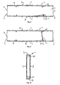
- Figure 1 is a side view of one embodiment of a closable weep hole according to the present invention, with part removed for clarity;
- Figure 2 is a view in the direction of the arrow shown in Figure 1 ;
- Figure 3 is a side view of another embodiment of a closable weep hole according to the present invention, with part being removed for clarity;
- Figure 4 is a view in the direction of the arrow in Figure 3 ;
- Figure 5 is a side view of a further embodiment of a closable weep hole according to the present invention in a first configuration, with part being removed for clarity;
- Figure 6 is a view corresponding to Figure 5 , in a second configuration
- Figure 7 is a view on a different scale in the direction of the arrow in Figure 5 ;
- Figure 8 is a side view of a further embodiment of a closable weep hole according to the present invention in a first configuration, with part being removed for clarity;
- Figure 9 is a view corresponding to Figure 8 , in a second configuration
- Figure 10 is a view on a different scale in the direction of the arrow in Figure 8 ;
- Figure 11 is a side view of an embodiment of a closable cowl in a first configuration, with part being removed for clarity;
- Figure 12 is a view corresponding to Figure 11 , in a second configuration.
- Figure 13 is a front view of the closable cowl shown in Figure 11 .
- the cowl disclosed in Figures 11 , 12 and 13 does not form part of the claimed invention.
- the closable weep hole shown in Figures 1 and 2 comprises a substantially rectangular hollow housing 1 which is designed, for example, to be positioned between adjacent bricks in the outer wall of a building, being held in place by mortar or the like.
- the weep hole may be made, for example, of high impact polystyrene which may be coloured to suit the intended application, such as buff or sand, terracotta or brown.
- the housing 1 is substantially the height and depth of a conventional brick and of a width so as to fit in the space conventionally provided between adjacent bricks, although the depth of the housing is such that at least a lower portion of the housing protrudes beyond the outer face of the brickwork.
- the rear 3 of the housing is open, while the front 2 is closed.
- the top 5 of the housing is also closed as are the sides 7, 9 (only one side being shown in Figure 1 ).
- the base 11 of the housing where it projects beyond the outer face of the brickwork is formed with an opening 13 for the outlet of moisture and/or water. The provision of the opening 13 in the base of the housing 1 reduces the likelihood of ingress of water or moisture in normal use of the weep hole.
- a projection 15 is provided, extending downwardly from the base 11, to assist positioning the housing 1 in the brickwork and reduces the likelihood of the brickwork becoming stained.
- the outlet opening is covered with a mesh 14 to prevent insects and the like entering the housing 1. If desired the rear 3 of the housing may also be covered with mesh.
- the valve 17 is pivotably mounted at an upper end thereof and in normal use bears lightly against the base of the housing while allowing moisture and liquid to flow through the housing to the outlet opening 13. However, in the event of a flood, when water enters the housing 1 through the opening 13, the pressure of the water urges the flap valve 17 firmly against the base of the housing so as to prevent the ingress of water through the housing and into the building. If desired, the lower edge of the valve may be chamfered to improve sealing with the base of the housing.
- the valve 17 is provided with a substantially cylindrical portion 19 which extends along the upper edge of the valve and is received in a complementary recess formed in a receiving portion 21 formed within the housing. The recess in the receiving portion is configured to allow pivoting of the valve relative to the housing.
- the housing 1 it is convenient to restrict the space within the housing 1 through which moisture and/or liquid can pass by providing a wall 23 which forms a passage 25 between the opening 13 and the open rear 3 of the housing.
- the wall 23 is ideally inclined such that the width of the passage is less in the region of the opening 13 than at the rear 3 of the housing.
- the receiving portion 21 is conveniently formed as part of the wall 23.
- the closable weep hole shown in Figures 3 and 4 is similar in principle to that described above in relation to Figures 1 and 2 and the same references are used to denote the same or similar components.
- the closable weep hole shown in Figures 3 and 4 comprises a housing 1 which is substantially triangular in configuration, but ideally with a portion of constant height in the region of the rear 3 of the housing and a portion of constant height in the region of the front 2 of the housing. The reduced height in the region of the outer face of the brickwork reduces the visual impact of the weep hole.
- the weep hole of Figures 3 and 4 is designed, for example, to be positioned between adjacent bricks in the outer wall of a building, being held in position with mortar or the like, the mortar also filling the space the housing does not occupy.
- the housing 1 at its highest point is substantially the height of a conventional brick and at its deepest point is substantially the depth of a conventional brick.
- the housing is of a width so as to fit in the space conventionally provided between adjacent bricks.
- the front 2 and rear 3 of the housing are open.
- the top 5 and base 11 of the housing are closed as are the sides 7, 9 (only one side being shown in Figure 3 ).
- the front 2 of the housing is formed with an opening 13 for the outlet of moisture and/or water.
- a plurality of projections 27 is provided, extending upwardly from the top of the housing, to assist securing the housing 1 in the brickwork.
- the outlet opening is covered with a mesh 14 to prevent insects and the like entering the housing 1. If desired, the rear of the housing may also be covered with mesh.
- a flap valve 17 mounted within the housing 1 is a flap valve 17.
- the valve 17 is pivotably mounted at an upper end thereof to the top wall of the housing in a region where the wall is inclined. In normal use the valve bears lightly against the base of the housing while allowing moisture and liquid to flow through the housing to the outlet opening 13. However, in the event of a flood, when water enters the housing 1 through the opening 13, the pressure of the water urges the flap valve 17 firmly against the base of the housing so as to prevent the ingress of water through the housing and into the building. If desired, the lower edge of the valve may be chamfered to improve sealing with the base of the housing.
- the valve 17 is provided with a substantially cylindrical portion 19 which extends along the upper edge of the valve and is received in a complementary recess formed in a receiving portion 21 formed within the housing.
- the recess in the receiving portion is configured to allow pivoting of the valve relative to the housing.
- the receiving portion 21 is conveniently formed as part of the upper inclined wall 5 of the housing.
- the closable weep hole shown in Figures 5 to 7 comprises a substantially rectangular hollow housing 1 which is designed, for example, to be positioned between adjacent bricks in the outer wall of a building, being held in place by mortar or the like.
- the weep hole may be made, for example, of high impact polystyrene which may be coloured to suit the intended application, such as buff or sand, terracotta, brown, grey or white, or may be substantially colourless.
- the housing 1 is substantially the height and depth of a conventional brick and of a width so as to fit in the space conventionally provided between adjacent bricks.
- the front 2 and rear 3 of the housing are open to allow the outlet of moisture and/or liquid from the building, the front 2 incorporating the opening 13.
- the top 7 and base 11 of the housing are closed as are the sides 7, 9 (only one side being shown in Figures 5 and 6 ).
- the outlet opening 13 at the front 2, and the rear 3, of the housing are covered with a mesh 14 to prevent insects and the like entering the housing 1.
- a flap valve 17 which is made of a material having a specific gravity less than that of water.
- the valve 17 is pivotably mounted at a lower end thereof and in normal use rests against the base of the housing, as shown in Figure 5 , while allowing moisture and liquid to flow through the housing to the outlet opening 13.
- the flap valve 17, or at least the free end thereof floats on the water and bears against a sealing lip 29 which is positioned within the top 5 of the housing (and optionally within the sides 7, 9 of the housing), as shown in Figure 6 , to seal the flap valve 17 against the sealing lip 29 so as to prevent the ingress of water through the housing and into the building.
- the sealing lip 29 may be configured such that it is engaged by the valve 17 before the valve reaches an upright orientation.
- the valve 17 is provided with a substantially cylindrical portion 19 which extends along the lower edge of the valve and is received in a complementary recess formed in a receiving portion 21 formed on the base 11 of the housing.
- the recess in the receiving portion is configured to allow pivoting of the valve relative to the housing.
- the closable weep hole shown in Figures 8 to 10 comprises a substantially rectangular hollow housing 1 which is designed, for example, to be positioned between adjacent bricks in the outer wall of a building, being held in place by mortar or the like.
- the weep hole may be made, for example, of high impact polystyrene which may be coloured to suit the intended application, such as buff or sand, terracotta, brown, grey or white, or may be substantially colourless.
- the housing 1 is substantially the height of a conventional brick and of a width so as to fit in the space conventionally provided between adjacent bricks. The depth of the housing is such that it will extend in use through the outer brickwork and across a cavity within a wall of a building so as to provide underfloor ventilation within the building.
- the front 2 and rear 3 of the housing are open to allow the outlet of moisture and/or liquid from the building, the front 2 incorporating the opening 13.
- the top 7 and base 11 of the housing are closed as are the sides 7, 9 (only one side being shown in Figures 8 and 9 ).
- the outlet opening 13 at the front 2, and the rear 3, of the housing are covered with a mesh 14 to prevent insects and the like entering the housing 1.
- a flap valve 17 which is made of a material having a specific gravity less than that of water.
- the valve 17 is pivotably mounted at a lower end thereof and in normal use rests against the base of the housing, as shown in Figure 8 , while allowing moisture to pass through the housing to the outlet opening 13.
- the flap valve 17, or at least the free end thereof floats on the water and, as shown in Figure 9 , bears against a sealing lip 29 which extends around the internal periphery of the housing 1 to seal the flap valve 17 against the sealing lip 29 so as to prevent the ingress of water through the housing and into the building.
- the sealing lip 29 may be configured such that it is engaged by the valve 17 before the valve 17 reaches an upright orientation.
- the valve 17 is provided with a substantially cylindrical portion 19 which extends along the lower edge of the valve and is received in a complementary recess formed in a receiving portion constituted by that part of the sealing lip 29 formed on the base 11 of the housing.
- the recess in the sealing lip is configured to allow pivoting of the valve relative to the housing.
- a further lip 31 extends around the internal periphery of the housing 1 between the free end of the valve 17 and the opening 13 in the front wall 2.
- the lip 31, together with the lip 29, prevent flow of small amounts of liquid through the housing, while not inhibiting the flow of moisture.
- a plurality of external ribs 33 extend around the periphery of the housing 1 and inhibit the flow of liquid along the outside of the housing.
- the lip 31 and the ribs 33 can be provided in respect on any of the weep holes described hereinabove.
- the cowl shown in Figures 11 to 13 comprises a housing 101 which includes a front wall 103, substantially triangular side walls 105, 107 and a flange 109 surrounding the walls and adapted to bear against a wall 111 of a building.
- the flange 109 also extends along a lower edge of the housing so as to define an opening within the flange which can be arranged around the opening in the building wall.
- the flange is provided with a number of apertures 113 for securing the cowl to the wall of the building in a watertight manner.
- the lower face of the cowl is open, but is covered with a mesh 115.
- a flap valve 117 mounted within the housing is a flap valve 117, of material having a specific gravity less than 1, which is pivotably mounted to a lower region of the flange 109 and in normal use bears against the mesh 115 (or a lower stop (not shown)).
- the valve 117 rises and seals against a sealing lip 119 which extends along the internal face of the front 103 and optionally along the inner faces of the sides 105, 107 to prevent the ingress of water.
- the valve 117 is formed with a substantially cylindrical portion 121 which is pivotably mounted in a complementary recess formed in a receiving portion 123 formed on the flange 109. As the flood water recedes the valve opens to allow air flow to the opening once again.
Landscapes
- Engineering & Computer Science (AREA)
- Architecture (AREA)
- Structural Engineering (AREA)
- Physics & Mathematics (AREA)
- Electromagnetism (AREA)
- Civil Engineering (AREA)
- Mechanical Engineering (AREA)
- General Engineering & Computer Science (AREA)
- Combustion & Propulsion (AREA)
- Chemical & Material Sciences (AREA)
- Check Valves (AREA)
- Valve Housings (AREA)
- Domestic Plumbing Installations (AREA)
- Infusion, Injection, And Reservoir Apparatuses (AREA)
- Self-Closing Valves And Venting Or Aerating Valves (AREA)
Claims (15)
- Verschließbares Durchflusselement, das ein Ablaufloch bildet, umfassend ein Gehäuse (1, 101), durch das ein Strömungsweg für Feuchtigkeit und/oder Flüssigkeit definiert ist, und ein Rückschlagventil (17, 117) in Form eines schwenkbaren Klappenventils, das in dem Gehäuse vorgesehen und zum Schließen im Falle eines erheblichen Flüssigkeitsflusses in einer Richtung ausgelegt ist, um zu verhindern, dass bei Hochwasser Wasser durch das Gehäuse fließt.
- Durchflusselement nach Anspruch 1, wobei das Ventil (17, 117) eine Ventilplatte aufweist, die entlang einer Oberkante davon schwenkbar montiert ist und auf der Basis des Gehäuses (1, 101) entlang einer Unterkante davon anliegt, wobei die Unterkante der Ventilplatte optional abgeschrägt ist.
- Durchflusselement nach Anspruch 1, wobei das Ventil (17, 117) eine Ventilplatte aufweist, die um eine Unterkante davon schwenkbar montiert ist und beim Gebrauch an einer Dichtungslippe (29, 119) anliegt, die auf einer Innenfläche des oberen Endes des Gehäuses (1, 101) ausgebildet ist, wobei die Dichtungslippe (29, 119) optional zusätzlich an Seitenwänden (7, 9) des Gehäuses (1, 101) ausgebildet ist.
- Durchflusselement nach Anspruch 1, wobei das Ventil (17) eine Ventilplatte aufweist, die in der Region der Vorderseite (2) oder der Hinterseite (3) des Gehäuses (1) schwenkbar montiert ist und beim Gebrauch an einer Dichtungslippe (29) anliegt, die auf einer Innenfläche des anderen aus Vorderseite und Hinterseite des Gehäuses ausgebildet ist, wobei die Dichtungslippe (29, 119) optional zusätzlich an Seitenwänden (7, 9, 105, 107) des Gehäuses (1, 101) ausgebildet ist.
- Durchflusselement nach Anspruch 3 oder 4, wobei das spezifische Gewicht der Ventilplatte geringer ist als das von Wasser.
- Durchflusselement nach einem vorherigen Anspruch, wobei das Klappenventil (17, 117) eine Ventilplatte aufweist, die einen im Wesentlichen zylindrischen Teil (19, 121) aufweist, der über eine Kante der Ventilplatte verläuft und in einer komplementären Aussparung in einem Aufnahmeteil (21, 123) aufgenommen wird, der Teil des Gehäuses (1, 101) bildet.
- Durchflusselement nach einem vorherigen Anspruch, wobei das Gehäuse (1) des Ablauflochs im Wesentlichen rechteckig ist, wobei das im Wesentlichen rechteckige Gehäuse (1) optional Folgendes beinhaltet: eine geneigte Frontwand und eine Öffnung (13) in der Region der Vorderseite (2) des Gehäuses in der Basis (11) des Gehäuses unterhalb der geneigten Frontwand.
- Durchflusselement nach Anspruch 8, wobei ein nach unten verlaufender Vorsprung (15) auf der Seite der Öffnung (13) fern von der Frontwand (2) vorgesehen ist.
- Durchflusselement nach einem vorherigen Anspruch, wobei das Gehäuse (1) eine geneigte Innenwand (23) aufweist, die den Strömungsweg (25) durch das Gehäuse definiert, wobei der Strömungsweg in der Region der Vorderseite (2) des Gehäuses schmäler ist als in der Region der Hinterseite (3) des Gehäuses.
- Durchflusselement nach einem vorherigen Anspruch, wobei die Vorderseite (2) und die Hinterseite (3) des Gehäuses (1) offen sind.
- Durchflusselement nach einem vorherigen Anspruch, wobei das Gehäuse (1) mit einer oder mehreren inneren Lippen (31) versehen ist, die um die Peripherie des Gehäuses verlaufen, um den Flüssigkeitsfluss durch das Gehäuse zu minimieren.
- Durchflusselement nach einem vorherigen Anspruch, wobei das Gehäuse (1) mit einer oder mehreren Rippen (33) versehen ist, die extern um die Peripherie des Gehäuses verlaufen, um den Fluss von Flüssigkeit extern entlang dem Gehäuse zu minimieren.
- Durchflusselement nach einem vorherigen Anspruch, wobei das Gehäuse (1) im Wesentlichen dreieckig ist, wobei das Gehäuse eine relativ niedrige vordere Region (2) und eine relativ große hintere Region (3) aufweist, wobei die Öffnung an der vorderen Region (2) des Gehäuses (1) beispielsweise in dessen Vorderwand vorgesehen ist.
- Durchflusselement nach Anspruch 13, wobei eine geneigte Wand (5) des Gehäuses (1) mit einem oder mehreren Vorsprüngen (27) versehen ist, um beim Befestigen des Gehäuses in einer Wand des Gebäudes zu assistieren.
- Durchflusselement nach Anspruch 13 oder 14, wobei ein Aufnahmeteil (21) für das Ventil (17) als Teil einer geneigten Außenwand (5) des Gehäuses (1) ausgebildet ist.
Applications Claiming Priority (2)
| Application Number | Priority Date | Filing Date | Title |
|---|---|---|---|
| GB0919555A GB0919555D0 (en) | 2009-11-09 | 2009-11-09 | Closable throughflow member |
| PCT/EP2010/066571 WO2011054780A2 (en) | 2009-11-09 | 2010-11-01 | Closable throughflow member |
Publications (2)
| Publication Number | Publication Date |
|---|---|
| EP2499306A2 EP2499306A2 (de) | 2012-09-19 |
| EP2499306B1 true EP2499306B1 (de) | 2013-08-28 |
Family
ID=41502064
Family Applications (1)
| Application Number | Title | Priority Date | Filing Date |
|---|---|---|---|
| EP20100771470 Active EP2499306B1 (de) | 2009-11-09 | 2010-11-01 | Verschliessbares durchflusselement |
Country Status (5)
| Country | Link |
|---|---|
| US (1) | US20120266975A1 (de) |
| EP (1) | EP2499306B1 (de) |
| AU (1) | AU2010314174B2 (de) |
| GB (1) | GB0919555D0 (de) |
| WO (1) | WO2011054780A2 (de) |
Families Citing this family (14)
| Publication number | Priority date | Publication date | Assignee | Title |
|---|---|---|---|---|
| CA2770380C (en) * | 2011-04-15 | 2017-08-15 | Serge Ramsay | Exhaust vent |
| US9441854B2 (en) * | 2011-04-15 | 2016-09-13 | Serge Ramsay | Exhaust vent |
| US10543736B2 (en) * | 2012-10-17 | 2020-01-28 | Ford Global Technologies, Llc | Vehicle cabin air management |
| US9376803B1 (en) | 2015-04-08 | 2016-06-28 | Smart Vent Products, Inc. | Flood vent trigger systems |
| US10113309B2 (en) * | 2015-04-08 | 2018-10-30 | Smart Vent Products, Inc. | Flood vent barrier systems |
| US9624637B2 (en) * | 2015-04-08 | 2017-04-18 | Smart Vent Products, Inc. | Flood vent |
| US10619345B2 (en) * | 2015-12-10 | 2020-04-14 | Smart Vent Products, Inc. | Flood vent having a panel |
| US9637912B1 (en) | 2015-12-10 | 2017-05-02 | Smart Vent Products, Inc. | Flood vent having a panel |
| US9758982B2 (en) | 2015-12-10 | 2017-09-12 | Smart Vent Products, Inc. | Flood vent having a panel |
| US10385611B2 (en) * | 2015-12-10 | 2019-08-20 | Smart Vent Products, Inc. | Flood vent having a panel |
| US9719249B2 (en) | 2015-12-10 | 2017-08-01 | Smart Vent Products, Inc. | Flood vent having a panel |
| CN106949615B (zh) * | 2017-03-17 | 2019-06-07 | 珠海格力电器股份有限公司 | 出风结构、空调器的出风方法和空调器 |
| US10544949B1 (en) * | 2018-07-09 | 2020-01-28 | Ting-Chia Chang | Air circulation apparatus for building |
| GB201916157D0 (en) * | 2019-11-06 | 2019-12-18 | Rytons Building Products Ltd | A cavity weep hole duct made of metal |
Family Cites Families (10)
| Publication number | Priority date | Publication date | Assignee | Title |
|---|---|---|---|---|
| US418816A (en) * | 1890-01-07 | Sewer-trap | ||
| DE341431C (de) * | ||||
| US2882923A (en) * | 1955-06-28 | 1959-04-21 | Smolensky Michael | Backwater check means for drainage systems |
| US3429084A (en) | 1967-07-10 | 1969-02-25 | Ben Brewer | Insect-proof weep hole |
| GB2328457B (en) * | 1997-08-20 | 2001-08-15 | Walter Leonard Robinson | External cover for ventilation air brick |
| US6360493B1 (en) | 2000-06-07 | 2002-03-26 | Ignacio Torres, III | Weep hole insect barrier |
| GB0018217D0 (en) * | 2000-07-26 | 2000-09-13 | Douglas George C | Apparatus for flooding protection |
| GB2418932A (en) * | 2004-07-14 | 2006-04-12 | Derek Wainwright | Building vent flood defence structure |
| AU2008100183A4 (en) * | 2008-02-27 | 2008-05-08 | Kelly, Frank Mr | Smart Airbrick |
| EP2352894B9 (de) * | 2008-11-01 | 2018-02-21 | Bluewater Design Associates Limited | Lüfter |
-
2009
- 2009-11-09 GB GB0919555A patent/GB0919555D0/en not_active Ceased
-
2010
- 2010-11-01 WO PCT/EP2010/066571 patent/WO2011054780A2/en not_active Ceased
- 2010-11-01 AU AU2010314174A patent/AU2010314174B2/en active Active
- 2010-11-01 US US13/261,287 patent/US20120266975A1/en not_active Abandoned
- 2010-11-01 EP EP20100771470 patent/EP2499306B1/de active Active
Also Published As
| Publication number | Publication date |
|---|---|
| GB0919555D0 (en) | 2009-12-23 |
| AU2010314174B2 (en) | 2016-11-17 |
| US20120266975A1 (en) | 2012-10-25 |
| WO2011054780A2 (en) | 2011-05-12 |
| EP2499306A2 (de) | 2012-09-19 |
| WO2011054780A3 (en) | 2012-05-03 |
| AU2010314174A1 (en) | 2012-05-31 |
Similar Documents
| Publication | Publication Date | Title |
|---|---|---|
| EP2499306B1 (de) | Verschliessbares durchflusselement | |
| EP2352894B9 (de) | Lüfter | |
| JP6395618B2 (ja) | 土台水切り | |
| GB2461754A (en) | Air vent for use as an air brick with a float valve and insect mesh | |
| EP2682687A2 (de) | Entlüftungsschutz | |
| JP2009102806A (ja) | 軒天井換気口装置 | |
| JP2026012535A (ja) | 水切り部材 | |
| JP2010001732A (ja) | 通気見切材及び建築物の外壁構造 | |
| JP5486418B2 (ja) | カーテンウォール | |
| WO2006068924A2 (en) | Flashing method using air infiltration blocking skirt | |
| JP5457862B2 (ja) | 通気見切材及び建築物の外壁構造 | |
| JP5385168B2 (ja) | 通気見切材の端部部材及び建築物の外壁構造 | |
| JP2007170142A (ja) | サッシ窓 | |
| GB2370306A (en) | Air brick flood barrier with vent pipe | |
| JP5671372B2 (ja) | 窓上防水部材、窓縦枠用蓋部材、窓上防水構造 | |
| TWM559345U (zh) | 通風屋頂之改良構造 | |
| JP5898414B2 (ja) | 建物の外壁構造 | |
| JP4581710B2 (ja) | 免震住宅の外壁部における縁切構造 | |
| JP6328994B2 (ja) | 建具 | |
| JPH0735102Y2 (ja) | サッシ水切り構造 | |
| JP2014020169A (ja) | 外壁開口上部目地の水処理構造及び水処理部材 | |
| JP7150173B2 (ja) | 換気扇 | |
| JP2009221814A (ja) | 建物の基礎構造、及び、建物の建築工法 | |
| JP6482326B2 (ja) | サッシ | |
| JP2024115315A (ja) | 土台水切 |
Legal Events
| Date | Code | Title | Description |
|---|---|---|---|
| PUAI | Public reference made under article 153(3) epc to a published international application that has entered the european phase |
Free format text: ORIGINAL CODE: 0009012 |
|
| 17P | Request for examination filed |
Effective date: 20120504 |
|
| AK | Designated contracting states |
Kind code of ref document: A2 Designated state(s): AL AT BE BG CH CY CZ DE DK EE ES FI FR GB GR HR HU IE IS IT LI LT LU LV MC MK MT NL NO PL PT RO RS SE SI SK SM TR |
|
| DAX | Request for extension of the european patent (deleted) | ||
| GRAP | Despatch of communication of intention to grant a patent |
Free format text: ORIGINAL CODE: EPIDOSNIGR1 |
|
| INTG | Intention to grant announced |
Effective date: 20130415 |
|
| GRAS | Grant fee paid |
Free format text: ORIGINAL CODE: EPIDOSNIGR3 |
|
| GRAA | (expected) grant |
Free format text: ORIGINAL CODE: 0009210 |
|
| AK | Designated contracting states |
Kind code of ref document: B1 Designated state(s): AL AT BE BG CH CY CZ DE DK EE ES FI FR GB GR HR HU IE IS IT LI LT LU LV MC MK MT NL NO PL PT RO RS SE SI SK SM TR |
|
| REG | Reference to a national code |
Ref country code: GB Ref legal event code: FG4D |
|
| REG | Reference to a national code |
Ref country code: CH Ref legal event code: EP |
|
| REG | Reference to a national code |
Ref country code: AT Ref legal event code: REF Ref document number: 629464 Country of ref document: AT Kind code of ref document: T Effective date: 20130915 |
|
| REG | Reference to a national code |
Ref country code: IE Ref legal event code: FG4D |
|
| REG | Reference to a national code |
Ref country code: DE Ref legal event code: R096 Ref document number: 602010009871 Country of ref document: DE Effective date: 20131024 |
|
| REG | Reference to a national code |
Ref country code: AT Ref legal event code: MK05 Ref document number: 629464 Country of ref document: AT Kind code of ref document: T Effective date: 20130828 |
|
| REG | Reference to a national code |
Ref country code: LT Ref legal event code: MG4D |
|
| REG | Reference to a national code |
Ref country code: NL Ref legal event code: VDEP Effective date: 20130828 |
|
| PG25 | Lapsed in a contracting state [announced via postgrant information from national office to epo] |
Ref country code: SE Free format text: LAPSE BECAUSE OF FAILURE TO SUBMIT A TRANSLATION OF THE DESCRIPTION OR TO PAY THE FEE WITHIN THE PRESCRIBED TIME-LIMIT Effective date: 20130828 Ref country code: HR Free format text: LAPSE BECAUSE OF FAILURE TO SUBMIT A TRANSLATION OF THE DESCRIPTION OR TO PAY THE FEE WITHIN THE PRESCRIBED TIME-LIMIT Effective date: 20130828 Ref country code: IS Free format text: LAPSE BECAUSE OF FAILURE TO SUBMIT A TRANSLATION OF THE DESCRIPTION OR TO PAY THE FEE WITHIN THE PRESCRIBED TIME-LIMIT Effective date: 20131228 Ref country code: PT Free format text: LAPSE BECAUSE OF FAILURE TO SUBMIT A TRANSLATION OF THE DESCRIPTION OR TO PAY THE FEE WITHIN THE PRESCRIBED TIME-LIMIT Effective date: 20131230 Ref country code: AT Free format text: LAPSE BECAUSE OF FAILURE TO SUBMIT A TRANSLATION OF THE DESCRIPTION OR TO PAY THE FEE WITHIN THE PRESCRIBED TIME-LIMIT Effective date: 20130828 Ref country code: NO Free format text: LAPSE BECAUSE OF FAILURE TO SUBMIT A TRANSLATION OF THE DESCRIPTION OR TO PAY THE FEE WITHIN THE PRESCRIBED TIME-LIMIT Effective date: 20131128 Ref country code: CY Free format text: LAPSE BECAUSE OF FAILURE TO SUBMIT A TRANSLATION OF THE DESCRIPTION OR TO PAY THE FEE WITHIN THE PRESCRIBED TIME-LIMIT Effective date: 20130911 Ref country code: LT Free format text: LAPSE BECAUSE OF FAILURE TO SUBMIT A TRANSLATION OF THE DESCRIPTION OR TO PAY THE FEE WITHIN THE PRESCRIBED TIME-LIMIT Effective date: 20130828 |
|
| REG | Reference to a national code |
Ref country code: NL Ref legal event code: VDEP Effective date: 20130828 |
|
| PG25 | Lapsed in a contracting state [announced via postgrant information from national office to epo] |
Ref country code: LV Free format text: LAPSE BECAUSE OF FAILURE TO SUBMIT A TRANSLATION OF THE DESCRIPTION OR TO PAY THE FEE WITHIN THE PRESCRIBED TIME-LIMIT Effective date: 20130828 Ref country code: SI Free format text: LAPSE BECAUSE OF FAILURE TO SUBMIT A TRANSLATION OF THE DESCRIPTION OR TO PAY THE FEE WITHIN THE PRESCRIBED TIME-LIMIT Effective date: 20130828 Ref country code: BE Free format text: LAPSE BECAUSE OF FAILURE TO SUBMIT A TRANSLATION OF THE DESCRIPTION OR TO PAY THE FEE WITHIN THE PRESCRIBED TIME-LIMIT Effective date: 20130828 Ref country code: FI Free format text: LAPSE BECAUSE OF FAILURE TO SUBMIT A TRANSLATION OF THE DESCRIPTION OR TO PAY THE FEE WITHIN THE PRESCRIBED TIME-LIMIT Effective date: 20130828 Ref country code: PL Free format text: LAPSE BECAUSE OF FAILURE TO SUBMIT A TRANSLATION OF THE DESCRIPTION OR TO PAY THE FEE WITHIN THE PRESCRIBED TIME-LIMIT Effective date: 20130828 Ref country code: GR Free format text: LAPSE BECAUSE OF FAILURE TO SUBMIT A TRANSLATION OF THE DESCRIPTION OR TO PAY THE FEE WITHIN THE PRESCRIBED TIME-LIMIT Effective date: 20131129 |
|
| PG25 | Lapsed in a contracting state [announced via postgrant information from national office to epo] |
Ref country code: CY Free format text: LAPSE BECAUSE OF FAILURE TO SUBMIT A TRANSLATION OF THE DESCRIPTION OR TO PAY THE FEE WITHIN THE PRESCRIBED TIME-LIMIT Effective date: 20130828 |
|
| PG25 | Lapsed in a contracting state [announced via postgrant information from national office to epo] |
Ref country code: RO Free format text: LAPSE BECAUSE OF FAILURE TO SUBMIT A TRANSLATION OF THE DESCRIPTION OR TO PAY THE FEE WITHIN THE PRESCRIBED TIME-LIMIT Effective date: 20130828 Ref country code: NL Free format text: LAPSE BECAUSE OF FAILURE TO SUBMIT A TRANSLATION OF THE DESCRIPTION OR TO PAY THE FEE WITHIN THE PRESCRIBED TIME-LIMIT Effective date: 20130828 Ref country code: EE Free format text: LAPSE BECAUSE OF FAILURE TO SUBMIT A TRANSLATION OF THE DESCRIPTION OR TO PAY THE FEE WITHIN THE PRESCRIBED TIME-LIMIT Effective date: 20130828 Ref country code: SK Free format text: LAPSE BECAUSE OF FAILURE TO SUBMIT A TRANSLATION OF THE DESCRIPTION OR TO PAY THE FEE WITHIN THE PRESCRIBED TIME-LIMIT Effective date: 20130828 Ref country code: CZ Free format text: LAPSE BECAUSE OF FAILURE TO SUBMIT A TRANSLATION OF THE DESCRIPTION OR TO PAY THE FEE WITHIN THE PRESCRIBED TIME-LIMIT Effective date: 20130828 Ref country code: DK Free format text: LAPSE BECAUSE OF FAILURE TO SUBMIT A TRANSLATION OF THE DESCRIPTION OR TO PAY THE FEE WITHIN THE PRESCRIBED TIME-LIMIT Effective date: 20130828 |
|
| PG25 | Lapsed in a contracting state [announced via postgrant information from national office to epo] |
Ref country code: IT Free format text: LAPSE BECAUSE OF FAILURE TO SUBMIT A TRANSLATION OF THE DESCRIPTION OR TO PAY THE FEE WITHIN THE PRESCRIBED TIME-LIMIT Effective date: 20130828 Ref country code: ES Free format text: LAPSE BECAUSE OF FAILURE TO SUBMIT A TRANSLATION OF THE DESCRIPTION OR TO PAY THE FEE WITHIN THE PRESCRIBED TIME-LIMIT Effective date: 20130828 |
|
| REG | Reference to a national code |
Ref country code: DE Ref legal event code: R097 Ref document number: 602010009871 Country of ref document: DE |
|
| REG | Reference to a national code |
Ref country code: GB Ref legal event code: 732E Free format text: REGISTERED BETWEEN 20140605 AND 20140611 |
|
| PLBE | No opposition filed within time limit |
Free format text: ORIGINAL CODE: 0009261 |
|
| STAA | Information on the status of an ep patent application or granted ep patent |
Free format text: STATUS: NO OPPOSITION FILED WITHIN TIME LIMIT |
|
| PG25 | Lapsed in a contracting state [announced via postgrant information from national office to epo] |
Ref country code: MC Free format text: LAPSE BECAUSE OF FAILURE TO SUBMIT A TRANSLATION OF THE DESCRIPTION OR TO PAY THE FEE WITHIN THE PRESCRIBED TIME-LIMIT Effective date: 20130828 |
|
| 26N | No opposition filed |
Effective date: 20140530 |
|
| REG | Reference to a national code |
Ref country code: DE Ref legal event code: R119 Ref document number: 602010009871 Country of ref document: DE Effective date: 20140603 |
|
| REG | Reference to a national code |
Ref country code: FR Ref legal event code: ST Effective date: 20140731 |
|
| PG25 | Lapsed in a contracting state [announced via postgrant information from national office to epo] |
Ref country code: DE Free format text: LAPSE BECAUSE OF NON-PAYMENT OF DUE FEES Effective date: 20140603 |
|
| REG | Reference to a national code |
Ref country code: DE Ref legal event code: R097 Ref document number: 602010009871 Country of ref document: DE Effective date: 20140530 |
|
| PG25 | Lapsed in a contracting state [announced via postgrant information from national office to epo] |
Ref country code: FR Free format text: LAPSE BECAUSE OF NON-PAYMENT OF DUE FEES Effective date: 20131202 |
|
| PG25 | Lapsed in a contracting state [announced via postgrant information from national office to epo] |
Ref country code: SM Free format text: LAPSE BECAUSE OF FAILURE TO SUBMIT A TRANSLATION OF THE DESCRIPTION OR TO PAY THE FEE WITHIN THE PRESCRIBED TIME-LIMIT Effective date: 20130828 |
|
| REG | Reference to a national code |
Ref country code: CH Ref legal event code: PL |
|
| PG25 | Lapsed in a contracting state [announced via postgrant information from national office to epo] |
Ref country code: LU Free format text: LAPSE BECAUSE OF NON-PAYMENT OF DUE FEES Effective date: 20131101 Ref country code: MK Free format text: LAPSE BECAUSE OF FAILURE TO SUBMIT A TRANSLATION OF THE DESCRIPTION OR TO PAY THE FEE WITHIN THE PRESCRIBED TIME-LIMIT Effective date: 20130828 Ref country code: RS Free format text: LAPSE BECAUSE OF FAILURE TO SUBMIT A TRANSLATION OF THE DESCRIPTION OR TO PAY THE FEE WITHIN THE PRESCRIBED TIME-LIMIT Effective date: 20131128 Ref country code: BG Free format text: LAPSE BECAUSE OF FAILURE TO SUBMIT A TRANSLATION OF THE DESCRIPTION OR TO PAY THE FEE WITHIN THE PRESCRIBED TIME-LIMIT Effective date: 20130828 Ref country code: HU Free format text: LAPSE BECAUSE OF FAILURE TO SUBMIT A TRANSLATION OF THE DESCRIPTION OR TO PAY THE FEE WITHIN THE PRESCRIBED TIME-LIMIT; INVALID AB INITIO Effective date: 20101101 Ref country code: CH Free format text: LAPSE BECAUSE OF NON-PAYMENT OF DUE FEES Effective date: 20141130 Ref country code: LI Free format text: LAPSE BECAUSE OF NON-PAYMENT OF DUE FEES Effective date: 20141130 |
|
| PG25 | Lapsed in a contracting state [announced via postgrant information from national office to epo] |
Ref country code: MT Free format text: LAPSE BECAUSE OF FAILURE TO SUBMIT A TRANSLATION OF THE DESCRIPTION OR TO PAY THE FEE WITHIN THE PRESCRIBED TIME-LIMIT Effective date: 20130828 |
|
| PG25 | Lapsed in a contracting state [announced via postgrant information from national office to epo] |
Ref country code: TR Free format text: LAPSE BECAUSE OF FAILURE TO SUBMIT A TRANSLATION OF THE DESCRIPTION OR TO PAY THE FEE WITHIN THE PRESCRIBED TIME-LIMIT Effective date: 20130828 |
|
| PG25 | Lapsed in a contracting state [announced via postgrant information from national office to epo] |
Ref country code: AL Free format text: LAPSE BECAUSE OF FAILURE TO SUBMIT A TRANSLATION OF THE DESCRIPTION OR TO PAY THE FEE WITHIN THE PRESCRIBED TIME-LIMIT Effective date: 20130828 |
|
| REG | Reference to a national code |
Ref country code: GB Ref legal event code: 732E Free format text: REGISTERED BETWEEN 20190314 AND 20190320 |
|
| REG | Reference to a national code |
Ref country code: GB Ref legal event code: 732E Free format text: REGISTERED BETWEEN 20220915 AND 20220921 |
|
| PGFP | Annual fee paid to national office [announced via postgrant information from national office to epo] |
Ref country code: GB Payment date: 20251029 Year of fee payment: 16 |
|
| PGFP | Annual fee paid to national office [announced via postgrant information from national office to epo] |
Ref country code: IE Payment date: 20251030 Year of fee payment: 16 |