EP2499306B1 - Closable throughflow member - Google Patents
Closable throughflow member Download PDFInfo
- Publication number
- EP2499306B1 EP2499306B1 EP20100771470 EP10771470A EP2499306B1 EP 2499306 B1 EP2499306 B1 EP 2499306B1 EP 20100771470 EP20100771470 EP 20100771470 EP 10771470 A EP10771470 A EP 10771470A EP 2499306 B1 EP2499306 B1 EP 2499306B1
- Authority
- EP
- European Patent Office
- Prior art keywords
- housing
- valve
- throughflow member
- throughflow
- region
- Prior art date
- Legal status (The legal status is an assumption and is not a legal conclusion. Google has not performed a legal analysis and makes no representation as to the accuracy of the status listed.)
- Active
Links
- XLYOFNOQVPJJNP-UHFFFAOYSA-N water Substances O XLYOFNOQVPJJNP-UHFFFAOYSA-N 0.000 claims description 27
- 238000007789 sealing Methods 0.000 claims description 19
- 239000007788 liquid Substances 0.000 claims description 16
- 230000000295 complement effect Effects 0.000 claims description 7
- 230000005484 gravity Effects 0.000 claims description 6
- 239000011449 brick Substances 0.000 description 13
- 241000238631 Hexapoda Species 0.000 description 12
- 239000004570 mortar (masonry) Substances 0.000 description 5
- 230000004888 barrier function Effects 0.000 description 3
- 238000010276 construction Methods 0.000 description 3
- 229920005669 high impact polystyrene Polymers 0.000 description 3
- 239000004797 high-impact polystyrene Substances 0.000 description 3
- 239000000463 material Substances 0.000 description 3
- 239000004576 sand Substances 0.000 description 3
- 230000009193 crawling Effects 0.000 description 2
- 238000009833 condensation Methods 0.000 description 1
- 230000005494 condensation Effects 0.000 description 1
- 230000003292 diminished effect Effects 0.000 description 1
- 230000000694 effects Effects 0.000 description 1
- 230000002401 inhibitory effect Effects 0.000 description 1
- 230000009545 invasion Effects 0.000 description 1
- 238000009423 ventilation Methods 0.000 description 1
- 230000000007 visual effect Effects 0.000 description 1
Images


Classifications
-
- E—FIXED CONSTRUCTIONS
- E04—BUILDING
- E04B—GENERAL BUILDING CONSTRUCTIONS; WALLS, e.g. PARTITIONS; ROOFS; FLOORS; CEILINGS; INSULATION OR OTHER PROTECTION OF BUILDINGS
- E04B1/00—Constructions in general; Structures which are not restricted either to walls, e.g. partitions, or floors or ceilings or roofs
- E04B1/62—Insulation or other protection; Elements or use of specified material therefor
- E04B1/70—Drying or keeping dry, e.g. by air vents
- E04B1/7038—Evacuating water from cavity walls, e.g. by using weep holes
- E04B1/7053—Grills for weep holes
-
- E—FIXED CONSTRUCTIONS
- E04—BUILDING
- E04B—GENERAL BUILDING CONSTRUCTIONS; WALLS, e.g. PARTITIONS; ROOFS; FLOORS; CEILINGS; INSULATION OR OTHER PROTECTION OF BUILDINGS
- E04B1/00—Constructions in general; Structures which are not restricted either to walls, e.g. partitions, or floors or ceilings or roofs
- E04B1/62—Insulation or other protection; Elements or use of specified material therefor
- E04B1/70—Drying or keeping dry, e.g. by air vents
- E04B1/7069—Drying or keeping dry, e.g. by air vents by ventilating
- E04B1/7076—Air vents for walls
-
- F—MECHANICAL ENGINEERING; LIGHTING; HEATING; WEAPONS; BLASTING
- F24—HEATING; RANGES; VENTILATING
- F24F—AIR-CONDITIONING; AIR-HUMIDIFICATION; VENTILATION; USE OF AIR CURRENTS FOR SCREENING
- F24F13/00—Details common to, or for air-conditioning, air-humidification, ventilation or use of air currents for screening
- F24F13/08—Air-flow control members, e.g. louvres, grilles, flaps or guide plates
- F24F13/082—Grilles, registers or guards
-
- F—MECHANICAL ENGINEERING; LIGHTING; HEATING; WEAPONS; BLASTING
- F24—HEATING; RANGES; VENTILATING
- F24F—AIR-CONDITIONING; AIR-HUMIDIFICATION; VENTILATION; USE OF AIR CURRENTS FOR SCREENING
- F24F2221/00—Details or features not otherwise provided for
- F24F2221/52—Weather protecting means, e.g. against wind, rain or snow
-
- Y—GENERAL TAGGING OF NEW TECHNOLOGICAL DEVELOPMENTS; GENERAL TAGGING OF CROSS-SECTIONAL TECHNOLOGIES SPANNING OVER SEVERAL SECTIONS OF THE IPC; TECHNICAL SUBJECTS COVERED BY FORMER USPC CROSS-REFERENCE ART COLLECTIONS [XRACs] AND DIGESTS
- Y10—TECHNICAL SUBJECTS COVERED BY FORMER USPC
- Y10T—TECHNICAL SUBJECTS COVERED BY FORMER US CLASSIFICATION
- Y10T137/00—Fluid handling
- Y10T137/6851—With casing, support, protector or static constructional installations
- Y10T137/6966—Static constructional installations
- Y10T137/6969—Buildings
Definitions
- This invention relates to a closable throughflow member in the form of a closable weep hole.
- weep holes are conventionally provided in walls, for example in the walls of buildings, to allow the escape of moisture and water through the wall.
- weep holes are generally overlooked in the event of a flood and can lead to ingress of flood water into a building and serious damage to the building itself and to the contents of the building.
- US 6360493 describes a weep hole insect barrier for existing and new construction that prevents insects from crawling into cavity walls in a typical house through weep holes.
- the insect barrier has a flap hinged to a frame. The frame is then secured to the outside of an existing weep hole. The flap contains a screen which prevents insects from crawling in while allowing moisture to escape from the cavity walls.
- the insect barrier also has a flap hinged to a frame, but the frame has two portions, a first portion having a flap and a second portion containing a fixed screen. In this case the frame can be secured within the weep hole.
- US 3429084 describes an insect-proof weep hole including a duct assembly, to permit circulation of air, and drain condensation from walls and to prevent invasion of insects, the duct assembly including a screen and an ant trap chamber. It is therefore an object of the present invention to provide a closable throughflow member in the form of a closable weephole which overcomes, or at least ameliorates, the problems associated with known such throughflow members.
- a closable throughflow member forming a weep hole comprising a housing defining a flow path for moisture and/or liquid therethrough, and a check valve in the form of a pivotable flap valve provided within the housing and adapted to close in the event of substantial liquid flow in one direction in order to prevent water flowing through the housing in the event of a flood.
- the housing may include an opening in a front region thereof which may be covered with a mesh for excluding insects from the housing.
- the housing may include an opening in a rear region thereof which may be covered with a mesh for excluding insects from the housing.
- the valve may include a valve plate pivotably mounted along an upper edge thereof and bearing on the base of the housing along a lower edge thereof.
- the lower edge of the valve plate may be chamfered.
- the valve may include a valve plate pivotably mounted about a lower edge thereof and bearing in use against a sealing lip formed on an internal face of the top of the housing. In such a case the specific gravity of the valve plate may be less than that of water.
- the sealing lip may additionally be formed on side walls of the housing.
- the valve may include a valve plate pivotably mounted in the region of one of the front and the rear of the housing and bearing in use against a sealing lip formed on an internal face of the other of the front and rear of the housing. In such a case, the specific gravity of the valve plate may be lass than that of water.
- the sealing lip may additionally be formed on side walls of the housing.
- the valve plate may include a substantially cylindrical portion extending across an edge of the valve plate and received in a complementary recess in a receiving portion forming part of the housing.
- the housing of the throughflow member may be substantially rectangular.
- the substantially rectangular housing may include an inclined front wall, the opening in the region of the front of the housing being formed in the base of the housing beneath the inclined front wall.
- a downwardly extending projection may be provided on that side of the opening remote from the front wall.
- the housing may include an inclined internal wall defining the flow path through the housing, the flow path being narrower in the region of the front of the housing than in the region of the rear of the housing.
- the receiving portion may be formed as part of the inclined wall.
- the front and rear of the housing may be open.
- the housing may be provided with one or more internal lips extending around the periphery of the housing so as to minimise the flow of liquid through the housing.
- the housing may be provided with one or more ribs extending externally around the periphery of the housing to minimise the flow of liquid externally along the housing.
- the housing of the throughflow member may be substantially triangular the housing having a relatively low front region and a relatively large rear region.
- the opening at the front region of the housing may be provided in the front wall thereof.
- the inclined wall of the housing may be provided with one or more projections to assist securing the housing in a wall of a building.
- the receiving portion may be formed as part of an inclined external wall of the housing.
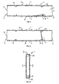
- Figure 1 is a side view of one embodiment of a closable weep hole according to the present invention, with part removed for clarity;
- Figure 2 is a view in the direction of the arrow shown in Figure 1 ;
- Figure 3 is a side view of another embodiment of a closable weep hole according to the present invention, with part being removed for clarity;
- Figure 4 is a view in the direction of the arrow in Figure 3 ;
- Figure 5 is a side view of a further embodiment of a closable weep hole according to the present invention in a first configuration, with part being removed for clarity;
- Figure 6 is a view corresponding to Figure 5 , in a second configuration
- Figure 7 is a view on a different scale in the direction of the arrow in Figure 5 ;
- Figure 8 is a side view of a further embodiment of a closable weep hole according to the present invention in a first configuration, with part being removed for clarity;
- Figure 9 is a view corresponding to Figure 8 , in a second configuration
- Figure 10 is a view on a different scale in the direction of the arrow in Figure 8 ;
- Figure 11 is a side view of an embodiment of a closable cowl in a first configuration, with part being removed for clarity;
- Figure 12 is a view corresponding to Figure 11 , in a second configuration.
- Figure 13 is a front view of the closable cowl shown in Figure 11 .
- the cowl disclosed in Figures 11 , 12 and 13 does not form part of the claimed invention.
- the closable weep hole shown in Figures 1 and 2 comprises a substantially rectangular hollow housing 1 which is designed, for example, to be positioned between adjacent bricks in the outer wall of a building, being held in place by mortar or the like.
- the weep hole may be made, for example, of high impact polystyrene which may be coloured to suit the intended application, such as buff or sand, terracotta or brown.
- the housing 1 is substantially the height and depth of a conventional brick and of a width so as to fit in the space conventionally provided between adjacent bricks, although the depth of the housing is such that at least a lower portion of the housing protrudes beyond the outer face of the brickwork.
- the rear 3 of the housing is open, while the front 2 is closed.
- the top 5 of the housing is also closed as are the sides 7, 9 (only one side being shown in Figure 1 ).
- the base 11 of the housing where it projects beyond the outer face of the brickwork is formed with an opening 13 for the outlet of moisture and/or water. The provision of the opening 13 in the base of the housing 1 reduces the likelihood of ingress of water or moisture in normal use of the weep hole.
- a projection 15 is provided, extending downwardly from the base 11, to assist positioning the housing 1 in the brickwork and reduces the likelihood of the brickwork becoming stained.
- the outlet opening is covered with a mesh 14 to prevent insects and the like entering the housing 1. If desired the rear 3 of the housing may also be covered with mesh.
- the valve 17 is pivotably mounted at an upper end thereof and in normal use bears lightly against the base of the housing while allowing moisture and liquid to flow through the housing to the outlet opening 13. However, in the event of a flood, when water enters the housing 1 through the opening 13, the pressure of the water urges the flap valve 17 firmly against the base of the housing so as to prevent the ingress of water through the housing and into the building. If desired, the lower edge of the valve may be chamfered to improve sealing with the base of the housing.
- the valve 17 is provided with a substantially cylindrical portion 19 which extends along the upper edge of the valve and is received in a complementary recess formed in a receiving portion 21 formed within the housing. The recess in the receiving portion is configured to allow pivoting of the valve relative to the housing.
- the housing 1 it is convenient to restrict the space within the housing 1 through which moisture and/or liquid can pass by providing a wall 23 which forms a passage 25 between the opening 13 and the open rear 3 of the housing.
- the wall 23 is ideally inclined such that the width of the passage is less in the region of the opening 13 than at the rear 3 of the housing.
- the receiving portion 21 is conveniently formed as part of the wall 23.
- the closable weep hole shown in Figures 3 and 4 is similar in principle to that described above in relation to Figures 1 and 2 and the same references are used to denote the same or similar components.
- the closable weep hole shown in Figures 3 and 4 comprises a housing 1 which is substantially triangular in configuration, but ideally with a portion of constant height in the region of the rear 3 of the housing and a portion of constant height in the region of the front 2 of the housing. The reduced height in the region of the outer face of the brickwork reduces the visual impact of the weep hole.
- the weep hole of Figures 3 and 4 is designed, for example, to be positioned between adjacent bricks in the outer wall of a building, being held in position with mortar or the like, the mortar also filling the space the housing does not occupy.
- the housing 1 at its highest point is substantially the height of a conventional brick and at its deepest point is substantially the depth of a conventional brick.
- the housing is of a width so as to fit in the space conventionally provided between adjacent bricks.
- the front 2 and rear 3 of the housing are open.
- the top 5 and base 11 of the housing are closed as are the sides 7, 9 (only one side being shown in Figure 3 ).
- the front 2 of the housing is formed with an opening 13 for the outlet of moisture and/or water.
- a plurality of projections 27 is provided, extending upwardly from the top of the housing, to assist securing the housing 1 in the brickwork.
- the outlet opening is covered with a mesh 14 to prevent insects and the like entering the housing 1. If desired, the rear of the housing may also be covered with mesh.
- a flap valve 17 mounted within the housing 1 is a flap valve 17.
- the valve 17 is pivotably mounted at an upper end thereof to the top wall of the housing in a region where the wall is inclined. In normal use the valve bears lightly against the base of the housing while allowing moisture and liquid to flow through the housing to the outlet opening 13. However, in the event of a flood, when water enters the housing 1 through the opening 13, the pressure of the water urges the flap valve 17 firmly against the base of the housing so as to prevent the ingress of water through the housing and into the building. If desired, the lower edge of the valve may be chamfered to improve sealing with the base of the housing.
- the valve 17 is provided with a substantially cylindrical portion 19 which extends along the upper edge of the valve and is received in a complementary recess formed in a receiving portion 21 formed within the housing.
- the recess in the receiving portion is configured to allow pivoting of the valve relative to the housing.
- the receiving portion 21 is conveniently formed as part of the upper inclined wall 5 of the housing.
- the closable weep hole shown in Figures 5 to 7 comprises a substantially rectangular hollow housing 1 which is designed, for example, to be positioned between adjacent bricks in the outer wall of a building, being held in place by mortar or the like.
- the weep hole may be made, for example, of high impact polystyrene which may be coloured to suit the intended application, such as buff or sand, terracotta, brown, grey or white, or may be substantially colourless.
- the housing 1 is substantially the height and depth of a conventional brick and of a width so as to fit in the space conventionally provided between adjacent bricks.
- the front 2 and rear 3 of the housing are open to allow the outlet of moisture and/or liquid from the building, the front 2 incorporating the opening 13.
- the top 7 and base 11 of the housing are closed as are the sides 7, 9 (only one side being shown in Figures 5 and 6 ).
- the outlet opening 13 at the front 2, and the rear 3, of the housing are covered with a mesh 14 to prevent insects and the like entering the housing 1.
- a flap valve 17 which is made of a material having a specific gravity less than that of water.
- the valve 17 is pivotably mounted at a lower end thereof and in normal use rests against the base of the housing, as shown in Figure 5 , while allowing moisture and liquid to flow through the housing to the outlet opening 13.
- the flap valve 17, or at least the free end thereof floats on the water and bears against a sealing lip 29 which is positioned within the top 5 of the housing (and optionally within the sides 7, 9 of the housing), as shown in Figure 6 , to seal the flap valve 17 against the sealing lip 29 so as to prevent the ingress of water through the housing and into the building.
- the sealing lip 29 may be configured such that it is engaged by the valve 17 before the valve reaches an upright orientation.
- the valve 17 is provided with a substantially cylindrical portion 19 which extends along the lower edge of the valve and is received in a complementary recess formed in a receiving portion 21 formed on the base 11 of the housing.
- the recess in the receiving portion is configured to allow pivoting of the valve relative to the housing.
- the closable weep hole shown in Figures 8 to 10 comprises a substantially rectangular hollow housing 1 which is designed, for example, to be positioned between adjacent bricks in the outer wall of a building, being held in place by mortar or the like.
- the weep hole may be made, for example, of high impact polystyrene which may be coloured to suit the intended application, such as buff or sand, terracotta, brown, grey or white, or may be substantially colourless.
- the housing 1 is substantially the height of a conventional brick and of a width so as to fit in the space conventionally provided between adjacent bricks. The depth of the housing is such that it will extend in use through the outer brickwork and across a cavity within a wall of a building so as to provide underfloor ventilation within the building.
- the front 2 and rear 3 of the housing are open to allow the outlet of moisture and/or liquid from the building, the front 2 incorporating the opening 13.
- the top 7 and base 11 of the housing are closed as are the sides 7, 9 (only one side being shown in Figures 8 and 9 ).
- the outlet opening 13 at the front 2, and the rear 3, of the housing are covered with a mesh 14 to prevent insects and the like entering the housing 1.
- a flap valve 17 which is made of a material having a specific gravity less than that of water.
- the valve 17 is pivotably mounted at a lower end thereof and in normal use rests against the base of the housing, as shown in Figure 8 , while allowing moisture to pass through the housing to the outlet opening 13.
- the flap valve 17, or at least the free end thereof floats on the water and, as shown in Figure 9 , bears against a sealing lip 29 which extends around the internal periphery of the housing 1 to seal the flap valve 17 against the sealing lip 29 so as to prevent the ingress of water through the housing and into the building.
- the sealing lip 29 may be configured such that it is engaged by the valve 17 before the valve 17 reaches an upright orientation.
- the valve 17 is provided with a substantially cylindrical portion 19 which extends along the lower edge of the valve and is received in a complementary recess formed in a receiving portion constituted by that part of the sealing lip 29 formed on the base 11 of the housing.
- the recess in the sealing lip is configured to allow pivoting of the valve relative to the housing.
- a further lip 31 extends around the internal periphery of the housing 1 between the free end of the valve 17 and the opening 13 in the front wall 2.
- the lip 31, together with the lip 29, prevent flow of small amounts of liquid through the housing, while not inhibiting the flow of moisture.
- a plurality of external ribs 33 extend around the periphery of the housing 1 and inhibit the flow of liquid along the outside of the housing.
- the lip 31 and the ribs 33 can be provided in respect on any of the weep holes described hereinabove.
- the cowl shown in Figures 11 to 13 comprises a housing 101 which includes a front wall 103, substantially triangular side walls 105, 107 and a flange 109 surrounding the walls and adapted to bear against a wall 111 of a building.
- the flange 109 also extends along a lower edge of the housing so as to define an opening within the flange which can be arranged around the opening in the building wall.
- the flange is provided with a number of apertures 113 for securing the cowl to the wall of the building in a watertight manner.
- the lower face of the cowl is open, but is covered with a mesh 115.
- a flap valve 117 mounted within the housing is a flap valve 117, of material having a specific gravity less than 1, which is pivotably mounted to a lower region of the flange 109 and in normal use bears against the mesh 115 (or a lower stop (not shown)).
- the valve 117 rises and seals against a sealing lip 119 which extends along the internal face of the front 103 and optionally along the inner faces of the sides 105, 107 to prevent the ingress of water.
- the valve 117 is formed with a substantially cylindrical portion 121 which is pivotably mounted in a complementary recess formed in a receiving portion 123 formed on the flange 109. As the flood water recedes the valve opens to allow air flow to the opening once again.
Landscapes
- Engineering & Computer Science (AREA)
- Architecture (AREA)
- Physics & Mathematics (AREA)
- Electromagnetism (AREA)
- Civil Engineering (AREA)
- Structural Engineering (AREA)
- Chemical & Material Sciences (AREA)
- Combustion & Propulsion (AREA)
- Mechanical Engineering (AREA)
- General Engineering & Computer Science (AREA)
- Check Valves (AREA)
- Self-Closing Valves And Venting Or Aerating Valves (AREA)
- Infusion, Injection, And Reservoir Apparatuses (AREA)
- Domestic Plumbing Installations (AREA)
- Valve Housings (AREA)
Description
- This invention relates to a closable throughflow member in the form of a closable weep hole.
- Weep holes are conventionally provided in walls, for example in the walls of buildings, to allow the escape of moisture and water through the wall. However, weep holes are generally overlooked in the event of a flood and can lead to ingress of flood water into a building and serious damage to the building itself and to the contents of the building.
- It is known to provide removable covers for weep holes, but such covers are inconvenient to put in place whenever there is a risk of a flood and to remove after the flood danger has diminished.
-
US 6360493 describes a weep hole insect barrier for existing and new construction that prevents insects from crawling into cavity walls in a typical house through weep holes. For existing construction, the insect barrier has a flap hinged to a frame. The frame is then secured to the outside of an existing weep hole. The flap contains a screen which prevents insects from crawling in while allowing moisture to escape from the cavity walls. For new construction, the insect barrier also has a flap hinged to a frame, but the frame has two portions, a first portion having a flap and a second portion containing a fixed screen. In this case the frame can be secured within the weep hole. -
US 3429084 describes an insect-proof weep hole including a duct assembly, to permit circulation of air, and drain condensation from walls and to prevent invasion of insects, the duct assembly including a screen and an ant trap chamber.
It is therefore an object of the present invention to provide a closable throughflow member in the form of a closable weephole which overcomes, or at least ameliorates, the problems associated with known such throughflow members.
According to the present invention there is provided a closable throughflow member forming a weep hole comprising a housing defining a flow path for moisture and/or liquid therethrough, and a check valve in the form of a pivotable flap valve provided within the housing and adapted to close in the event of substantial liquid flow in one direction in order to prevent water flowing through the housing in the event of a flood.
The housing may include an opening in a front region thereof which may be covered with a mesh for excluding insects from the housing.
The housing may include an opening in a rear region thereof which may be covered with a mesh for excluding insects from the housing.
The valve may include a valve plate pivotably mounted along an upper edge thereof and bearing on the base of the housing along a lower edge thereof. The lower edge of the valve plate may be chamfered. Alternatively, the valve may include a valve plate pivotably mounted about a lower edge thereof and bearing in use against a sealing lip formed on an internal face of the top of the housing. In such a case the specific gravity of the valve plate may be less than that of water. The sealing lip may additionally be formed on side walls of the housing. As a further alternative, the valve may include a valve plate pivotably mounted in the region of one of the front and the rear of the housing and bearing in use against a sealing lip formed on an internal face of the other of the front and rear of the housing. In such a case, the specific gravity of the valve plate may be lass than that of water. The sealing lip may additionally be formed on side walls of the housing. The valve plate may include a substantially cylindrical portion extending across an edge of the valve plate and received in a complementary recess in a receiving portion forming part of the housing. - The housing of the throughflow member may be substantially rectangular. The substantially rectangular housing may include an inclined front wall, the opening in the region of the front of the housing being formed in the base of the housing beneath the inclined front wall. A downwardly extending projection may be provided on that side of the opening remote from the front wall. The housing may include an inclined internal wall defining the flow path through the housing, the flow path being narrower in the region of the front of the housing than in the region of the rear of the housing. The receiving portion may be formed as part of the inclined wall. Alternatively, the front and rear of the housing may be open. The housing may be provided with one or more internal lips extending around the periphery of the housing so as to minimise the flow of liquid through the housing. The housing may be provided with one or more ribs extending externally around the periphery of the housing to minimise the flow of liquid externally along the housing.
- Alternatively, the housing of the throughflow member may be substantially triangular the housing having a relatively low front region and a relatively large rear region. The opening at the front region of the housing may be provided in the front wall thereof. The inclined wall of the housing may be provided with one or more projections to assist securing the housing in a wall of a building. The receiving portion may be formed as part of an inclined external wall of the housing.
- For a better understanding of the present invention and to show more clearly how it may be carried into effect reference will now be made, by way of example, to the accompanying drawings in which:
-
Figure 1 is a side view of one embodiment of a closable weep hole according to the present invention, with part removed for clarity; -
Figure 2 is a view in the direction of the arrow shown inFigure 1 ; -
Figure 3 is a side view of another embodiment of a closable weep hole according to the present invention, with part being removed for clarity; -
Figure 4 is a view in the direction of the arrow inFigure 3 ; -
Figure 5 is a side view of a further embodiment of a closable weep hole according to the present invention in a first configuration, with part being removed for clarity; -
Figure 6 is a view corresponding toFigure 5 , in a second configuration; -
Figure 7 is a view on a different scale in the direction of the arrow inFigure 5 ; -
Figure 8 is a side view of a further embodiment of a closable weep hole according to the present invention in a first configuration, with part being removed for clarity; -
Figure 9 is a view corresponding toFigure 8 , in a second configuration; -
Figure 10 is a view on a different scale in the direction of the arrow inFigure 8 ; -
Figure 11 is a side view of an embodiment of a closable cowl in a first configuration, with part being removed for clarity; -
Figure 12 is a view corresponding toFigure 11 , in a second configuration; and -
Figure 13 is a front view of the closable cowl shown inFigure 11 . The cowl disclosed inFigures 11 ,12 and 13 does not form part of the claimed invention. - The closable weep hole shown in
Figures 1 and2 comprises a substantially rectangularhollow housing 1 which is designed, for example, to be positioned between adjacent bricks in the outer wall of a building, being held in place by mortar or the like. The weep hole may be made, for example, of high impact polystyrene which may be coloured to suit the intended application, such as buff or sand, terracotta or brown. Thehousing 1 is substantially the height and depth of a conventional brick and of a width so as to fit in the space conventionally provided between adjacent bricks, although the depth of the housing is such that at least a lower portion of the housing protrudes beyond the outer face of the brickwork. This may be accomplished by providing aninclined front wall 2 as part of the housing, with the lower part of the housing extending progressively beyond the outer face of the brickwork, or by dimensioning a rectangular housing such that theentire front wall 2 protrudes beyond the outer face of the brickwork. - The rear 3 of the housing is open, while the
front 2 is closed. Thetop 5 of the housing is also closed as are thesides 7, 9 (only one side being shown inFigure 1 ). Thebase 11 of the housing where it projects beyond the outer face of the brickwork is formed with anopening 13 for the outlet of moisture and/or water. The provision of theopening 13 in the base of thehousing 1 reduces the likelihood of ingress of water or moisture in normal use of the weep hole. A projection 15 is provided, extending downwardly from thebase 11, to assist positioning thehousing 1 in the brickwork and reduces the likelihood of the brickwork becoming stained. - The outlet opening is covered with a
mesh 14 to prevent insects and the like entering thehousing 1. If desired the rear 3 of the housing may also be covered with mesh. - Mounted within the
housing 1 is aflap valve 17. Thevalve 17 is pivotably mounted at an upper end thereof and in normal use bears lightly against the base of the housing while allowing moisture and liquid to flow through the housing to the outlet opening 13. However, in the event of a flood, when water enters thehousing 1 through theopening 13, the pressure of the water urges theflap valve 17 firmly against the base of the housing so as to prevent the ingress of water through the housing and into the building. If desired, the lower edge of the valve may be chamfered to improve sealing with the base of the housing. Thevalve 17 is provided with a substantiallycylindrical portion 19 which extends along the upper edge of the valve and is received in a complementary recess formed in a receivingportion 21 formed within the housing. The recess in the receiving portion is configured to allow pivoting of the valve relative to the housing. - In practice, it is convenient to restrict the space within the
housing 1 through which moisture and/or liquid can pass by providing awall 23 which forms apassage 25 between theopening 13 and theopen rear 3 of the housing. Thewall 23 is ideally inclined such that the width of the passage is less in the region of theopening 13 than at the rear 3 of the housing. The receivingportion 21 is conveniently formed as part of thewall 23. - The closable weep hole shown in
Figures 3 and4 is similar in principle to that described above in relation toFigures 1 and2 and the same references are used to denote the same or similar components. The closable weep hole shown inFigures 3 and4 comprises ahousing 1 which is substantially triangular in configuration, but ideally with a portion of constant height in the region of the rear 3 of the housing and a portion of constant height in the region of thefront 2 of the housing. The reduced height in the region of the outer face of the brickwork reduces the visual impact of the weep hole. As with the weep hole ofFigures 1 and2 , the weep hole ofFigures 3 and4 is designed, for example, to be positioned between adjacent bricks in the outer wall of a building, being held in position with mortar or the like, the mortar also filling the space the housing does not occupy. Thehousing 1 at its highest point is substantially the height of a conventional brick and at its deepest point is substantially the depth of a conventional brick. As with the embodiment ofFigures 1 and2 , the housing is of a width so as to fit in the space conventionally provided between adjacent bricks. - The
front 2 and rear 3 of the housing are open. The top 5 andbase 11 of the housing are closed as are thesides 7, 9 (only one side being shown inFigure 3 ). Thefront 2 of the housing is formed with anopening 13 for the outlet of moisture and/or water. A plurality ofprojections 27 is provided, extending upwardly from the top of the housing, to assist securing thehousing 1 in the brickwork. - The outlet opening is covered with a
mesh 14 to prevent insects and the like entering thehousing 1. If desired, the rear of the housing may also be covered with mesh. - Mounted within the
housing 1 is aflap valve 17. Thevalve 17 is pivotably mounted at an upper end thereof to the top wall of the housing in a region where the wall is inclined. In normal use the valve bears lightly against the base of the housing while allowing moisture and liquid to flow through the housing to theoutlet opening 13. However, in the event of a flood, when water enters thehousing 1 through theopening 13, the pressure of the water urges theflap valve 17 firmly against the base of the housing so as to prevent the ingress of water through the housing and into the building. If desired, the lower edge of the valve may be chamfered to improve sealing with the base of the housing. Thevalve 17 is provided with a substantiallycylindrical portion 19 which extends along the upper edge of the valve and is received in a complementary recess formed in a receivingportion 21 formed within the housing. The recess in the receiving portion is configured to allow pivoting of the valve relative to the housing. - In practice, the receiving
portion 21 is conveniently formed as part of the upperinclined wall 5 of the housing. - The closable weep hole shown in
Figures 5 to 7 is similar to that shown inFigures 1 and2 and the same references are used to denote the same or similar components. - The closable weep hole shown in
Figures 5 to 7 comprises a substantially rectangularhollow housing 1 which is designed, for example, to be positioned between adjacent bricks in the outer wall of a building, being held in place by mortar or the like. The weep hole may be made, for example, of high impact polystyrene which may be coloured to suit the intended application, such as buff or sand, terracotta, brown, grey or white, or may be substantially colourless. Thehousing 1 is substantially the height and depth of a conventional brick and of a width so as to fit in the space conventionally provided between adjacent bricks. - The
front 2 and rear 3 of the housing are open to allow the outlet of moisture and/or liquid from the building, thefront 2 incorporating theopening 13. The top 7 andbase 11 of the housing are closed as are thesides 7, 9 (only one side being shown inFigures 5 and6 ). - The
outlet opening 13 at thefront 2, and the rear 3, of the housing are covered with amesh 14 to prevent insects and the like entering thehousing 1. - Mounted within the
housing 1 is aflap valve 17 which is made of a material having a specific gravity less than that of water. Thevalve 17 is pivotably mounted at a lower end thereof and in normal use rests against the base of the housing, as shown inFigure 5 , while allowing moisture and liquid to flow through the housing to theoutlet opening 13. However, in the event of a flood, when water enters thehousing 1 through theopening 13, theflap valve 17, or at least the free end thereof, floats on the water and bears against a sealinglip 29 which is positioned within thetop 5 of the housing (and optionally within thesides Figure 6 , to seal theflap valve 17 against the sealinglip 29 so as to prevent the ingress of water through the housing and into the building. The sealinglip 29 may be configured such that it is engaged by thevalve 17 before the valve reaches an upright orientation. Thevalve 17 is provided with a substantiallycylindrical portion 19 which extends along the lower edge of the valve and is received in a complementary recess formed in a receivingportion 21 formed on thebase 11 of the housing. The recess in the receiving portion is configured to allow pivoting of the valve relative to the housing. - The closable weep hole shown in
Figures 8 to 10 is similar to that shown inFigures 5 to 7 and the same references are used to denote the same or similar components. - The closable weep hole shown in
Figures 8 to 10 comprises a substantially rectangularhollow housing 1 which is designed, for example, to be positioned between adjacent bricks in the outer wall of a building, being held in place by mortar or the like. The weep hole may be made, for example, of high impact polystyrene which may be coloured to suit the intended application, such as buff or sand, terracotta, brown, grey or white, or may be substantially colourless. Thehousing 1 is substantially the height of a conventional brick and of a width so as to fit in the space conventionally provided between adjacent bricks. The depth of the housing is such that it will extend in use through the outer brickwork and across a cavity within a wall of a building so as to provide underfloor ventilation within the building. - The
front 2 and rear 3 of the housing are open to allow the outlet of moisture and/or liquid from the building, thefront 2 incorporating theopening 13. The top 7 andbase 11 of the housing are closed as are thesides 7, 9 (only one side being shown inFigures 8 and 9 ). - The
outlet opening 13 at thefront 2, and the rear 3, of the housing are covered with amesh 14 to prevent insects and the like entering thehousing 1. - Mounted within the
housing 1 is aflap valve 17 which is made of a material having a specific gravity less than that of water. Thevalve 17 is pivotably mounted at a lower end thereof and in normal use rests against the base of the housing, as shown inFigure 8 , while allowing moisture to pass through the housing to theoutlet opening 13. However, in the event of a flood, when water enters thehousing 1 through theopening 13, theflap valve 17, or at least the free end thereof, floats on the water and, as shown inFigure 9 , bears against a sealinglip 29 which extends around the internal periphery of thehousing 1 to seal theflap valve 17 against the sealinglip 29 so as to prevent the ingress of water through the housing and into the building. The sealinglip 29 may be configured such that it is engaged by thevalve 17 before thevalve 17 reaches an upright orientation. Thevalve 17 is provided with a substantiallycylindrical portion 19 which extends along the lower edge of the valve and is received in a complementary recess formed in a receiving portion constituted by that part of the sealinglip 29 formed on thebase 11 of the housing. The recess in the sealing lip is configured to allow pivoting of the valve relative to the housing. - A
further lip 31 extends around the internal periphery of thehousing 1 between the free end of thevalve 17 and theopening 13 in thefront wall 2. Thelip 31, together with thelip 29, prevent flow of small amounts of liquid through the housing, while not inhibiting the flow of moisture. - A plurality of
external ribs 33 extend around the periphery of thehousing 1 and inhibit the flow of liquid along the outside of the housing. - Clearly the
lip 31 and theribs 33 can be provided in respect on any of the weep holes described hereinabove. - The cowl shown in
Figures 11 to 13 comprises ahousing 101 which includes afront wall 103, substantiallytriangular side walls 105, 107 and aflange 109 surrounding the walls and adapted to bear against a wall 111 of a building. Theflange 109 also extends along a lower edge of the housing so as to define an opening within the flange which can be arranged around the opening in the building wall. The flange is provided with a number ofapertures 113 for securing the cowl to the wall of the building in a watertight manner. The lower face of the cowl is open, but is covered with amesh 115. - Mounted within the housing is a
flap valve 117, of material having a specific gravity less than 1, which is pivotably mounted to a lower region of theflange 109 and in normal use bears against the mesh 115 (or a lower stop (not shown)). However, in the event of a flood, when water enters thehousing 101 thevalve 117 rises and seals against a sealinglip 119 which extends along the internal face of the front 103 and optionally along the inner faces of thesides 105, 107 to prevent the ingress of water. Thevalve 117 is formed with a substantiallycylindrical portion 121 which is pivotably mounted in a complementary recess formed in a receiving portion 123 formed on theflange 109. As the flood water recedes the valve opens to allow air flow to the opening once again.
Claims (15)
- A closable throughflow member forming a weep hole comprising a housing (1,101) defining a flow path for moisture and/or liquid therethrough, and a check valve (17, 117) in the form of a pivotable flap valve provided within the housing and adapted to close in the event of substantial liquid flow in one direction in order to prevent water flowing through the housing in the event of a flood.
- A throughflow member as claimed in claim 1, wherein the valve (17, 117) includes a valve plate pivotably mounted along an upper edge thereof and bearing on the base of the housing (1, 101) along a lower edge thereof, the lower edge of the valve plate optionally being chamfered.
- A throughflow member as claimed in claim 1, wherein the valve (17,117) includes a valve plate pivotably mounted about a lower edge thereof and bearing in use against a sealing lip (29, 119) formed on an internal face of the top of the housing (1, 101), the sealing lip (29,119) optionally being additionally formed on side walls (7, 9) of the housing (1, 101).
- A throughflow member as claimed in claim 1, wherein the valve (17) includes a valve plate pivotably mounted in the region of one of the front (2) and the rear (3) of the housing (1) and bearing in use against a sealing lip (29) formed on an internal face of the other of the front and rear of the housing, the sealing lip (29,119) optionally being additionally formed on side walls (7,9,105, 107) of the housing (1, 101).
- A throughflow member as claimed in claim 3 or 4, wherein the specific gravity of the valve plate is less than that of water.
- A throughflow member as claimed in any preceding claim, wherein the flap valve (17, 117) includes a valve plate which includes a substantially cylindrical portion (19, 121) extending across an edge of the valve plate and received in a complementary recess in a receiving portion (21,123) forming part of the housing (1,101).
- A throughflow member as claimed in any preceding claim, wherein the housing (1) of the weep hole is substantially rectangular, the substantially rectangular housing (1) optionally including: an inclined front wall, and an opening (13) in the region of the front (2) of the housing being formed in the base (11) of the housing beneath the inclined front wall.
- A throughflow member as claimed in claim 8, wherein a downwardly extending projection (15) is provided on that side of the opening (13) remote from the front wall (2).
- A throughflow member as claimed in any preceding claim, wherein the housing (1) includes an inclined internal wall (23) defining the flow path (25) through the housing, the flow path being narrower in the region of the front (2) of the housing than in the region of the rear (3) of the housing.
- A throughflow member as claimed in any preceding claim, wherein the front (2) and rear (3) of the housing (1) are open.
- A throughflow member as claimed in any preceding claim, wherein the housing (1) is provided with one or more internal lips (31) extending around the periphery of the housing so as to minimise the flow of liquid through the housing.
- A throughflow member as claimed in any preceding claim, wherein the housing (1) is provided with one or more ribs (33) extending externally around the periphery of the housing to minimise the flow of liquid externally along the housing.
- A throughflow member as claimed in any preceding claim, wherein the housing (1) is substantially triangular, the housing having a relatively low front region (2) and a relatively large rear region (3), the opening at the front region (2) of the housing (1) being provided, for example, in the front wall thereof.
- A throughflow member as claimed in claim 13, wherein an inclined wall (5) of the housing (1) is provided with one or more projections (27) to assist securing the housing in a wall of a building.
- A throughflow member as claimed in claim 13 or 14, wherein a receiving portion (21) for the valve (17) is formed as part of an inclined external wall (5) of the housing (1).
Applications Claiming Priority (2)
| Application Number | Priority Date | Filing Date | Title |
|---|---|---|---|
| GB0919555A GB0919555D0 (en) | 2009-11-09 | 2009-11-09 | Closable throughflow member |
| PCT/EP2010/066571 WO2011054780A2 (en) | 2009-11-09 | 2010-11-01 | Closable throughflow member |
Publications (2)
| Publication Number | Publication Date |
|---|---|
| EP2499306A2 EP2499306A2 (en) | 2012-09-19 |
| EP2499306B1 true EP2499306B1 (en) | 2013-08-28 |
Family
ID=41502064
Family Applications (1)
| Application Number | Title | Priority Date | Filing Date |
|---|---|---|---|
| EP20100771470 Active EP2499306B1 (en) | 2009-11-09 | 2010-11-01 | Closable throughflow member |
Country Status (5)
| Country | Link |
|---|---|
| US (1) | US20120266975A1 (en) |
| EP (1) | EP2499306B1 (en) |
| AU (1) | AU2010314174B2 (en) |
| GB (1) | GB0919555D0 (en) |
| WO (1) | WO2011054780A2 (en) |
Families Citing this family (14)
| Publication number | Priority date | Publication date | Assignee | Title |
|---|---|---|---|---|
| US9441854B2 (en) * | 2011-04-15 | 2016-09-13 | Serge Ramsay | Exhaust vent |
| CA2770380C (en) * | 2011-04-15 | 2017-08-15 | Serge Ramsay | Exhaust vent |
| US10543736B2 (en) * | 2012-10-17 | 2020-01-28 | Ford Global Technologies, Llc | Vehicle cabin air management |
| US9624637B2 (en) * | 2015-04-08 | 2017-04-18 | Smart Vent Products, Inc. | Flood vent |
| US10113309B2 (en) * | 2015-04-08 | 2018-10-30 | Smart Vent Products, Inc. | Flood vent barrier systems |
| US9376803B1 (en) | 2015-04-08 | 2016-06-28 | Smart Vent Products, Inc. | Flood vent trigger systems |
| US10385611B2 (en) * | 2015-12-10 | 2019-08-20 | Smart Vent Products, Inc. | Flood vent having a panel |
| US10619345B2 (en) * | 2015-12-10 | 2020-04-14 | Smart Vent Products, Inc. | Flood vent having a panel |
| US9758982B2 (en) | 2015-12-10 | 2017-09-12 | Smart Vent Products, Inc. | Flood vent having a panel |
| US9719249B2 (en) | 2015-12-10 | 2017-08-01 | Smart Vent Products, Inc. | Flood vent having a panel |
| US9637912B1 (en) | 2015-12-10 | 2017-05-02 | Smart Vent Products, Inc. | Flood vent having a panel |
| CN106949615B (en) * | 2017-03-17 | 2019-06-07 | 珠海格力电器股份有限公司 | Air outlet structure, air outlet method of air conditioner and air conditioner |
| US10544949B1 (en) * | 2018-07-09 | 2020-01-28 | Ting-Chia Chang | Air circulation apparatus for building |
| GB201916157D0 (en) * | 2019-11-06 | 2019-12-18 | Rytons Building Products Ltd | A cavity weep hole duct made of metal |
Family Cites Families (10)
| Publication number | Priority date | Publication date | Assignee | Title |
|---|---|---|---|---|
| DE341431C (en) * | ||||
| US418816A (en) * | 1890-01-07 | Sewer-trap | ||
| US2882923A (en) * | 1955-06-28 | 1959-04-21 | Smolensky Michael | Backwater check means for drainage systems |
| US3429084A (en) | 1967-07-10 | 1969-02-25 | Ben Brewer | Insect-proof weep hole |
| GB2328457B (en) * | 1997-08-20 | 2001-08-15 | Walter Leonard Robinson | External cover for ventilation air brick |
| US6360493B1 (en) | 2000-06-07 | 2002-03-26 | Ignacio Torres, III | Weep hole insect barrier |
| GB0018217D0 (en) * | 2000-07-26 | 2000-09-13 | Douglas George C | Apparatus for flooding protection |
| GB2418932A (en) * | 2004-07-14 | 2006-04-12 | Derek Wainwright | Building vent flood defence structure |
| AU2008100183A4 (en) * | 2008-02-27 | 2008-05-08 | Kelly, Frank Mr | Smart Airbrick |
| WO2010060705A2 (en) * | 2008-11-01 | 2010-06-03 | Kelly, John | Vent |
-
2009
- 2009-11-09 GB GB0919555A patent/GB0919555D0/en not_active Ceased
-
2010
- 2010-11-01 WO PCT/EP2010/066571 patent/WO2011054780A2/en active Application Filing
- 2010-11-01 AU AU2010314174A patent/AU2010314174B2/en active Active
- 2010-11-01 US US13/261,287 patent/US20120266975A1/en not_active Abandoned
- 2010-11-01 EP EP20100771470 patent/EP2499306B1/en active Active
Also Published As
| Publication number | Publication date |
|---|---|
| EP2499306A2 (en) | 2012-09-19 |
| WO2011054780A3 (en) | 2012-05-03 |
| AU2010314174B2 (en) | 2016-11-17 |
| US20120266975A1 (en) | 2012-10-25 |
| AU2010314174A1 (en) | 2012-05-31 |
| WO2011054780A2 (en) | 2011-05-12 |
| GB0919555D0 (en) | 2009-12-23 |
Similar Documents
| Publication | Publication Date | Title |
|---|---|---|
| EP2499306B1 (en) | Closable throughflow member | |
| US10787857B2 (en) | Vent | |
| GB2461754A (en) | Air vent for use as an air brick with a float valve and insect mesh | |
| EP2682687A2 (en) | Vent protector | |
| JP6395618B2 (en) | Foundation drainer | |
| JP2007170142A (en) | Sash window | |
| JP5385168B2 (en) | End member of ventilation parting material and outer wall structure of building | |
| TWM559345U (en) | Improved structure of ventilation roof | |
| GB2370306A (en) | Air brick flood barrier with vent pipe | |
| JP5671372B2 (en) | Waterproof member on window, lid member for window vertical frame, waterproof structure on window | |
| KR20130061831A (en) | Sliding system window for higher stories having drain hole cap | |
| JP6328994B2 (en) | Joinery | |
| JP7150173B2 (en) | ventilation fan | |
| JP5436789B2 (en) | Building basic structure and building construction method | |
| JPH0735102Y2 (en) | Sash drainer structure | |
| JP5898414B2 (en) | Building outer wall structure | |
| JP5457862B2 (en) | Venting material and exterior wall structure of buildings | |
| JP6482326B2 (en) | sash | |
| JP6496207B2 (en) | Water stop member, parting cover and horizontal joint water stop structure | |
| JP6339823B2 (en) | Seismic reinforcement frame mounting structure | |
| JP2005016247A (en) | Parapet and flat roof structure | |
| JP2019116779A (en) | Fixture | |
| JP2020183676A (en) | Waterproof construction of roof chimney penetration part | |
| JP2007132100A (en) | Cover for underfloor ventilation opening of building | |
| JPH10292938A (en) | Mounting structure of ventilating hood |
Legal Events
| Date | Code | Title | Description |
|---|---|---|---|
| PUAI | Public reference made under article 153(3) epc to a published international application that has entered the european phase |
Free format text: ORIGINAL CODE: 0009012 |
|
| 17P | Request for examination filed |
Effective date: 20120504 |
|
| AK | Designated contracting states |
Kind code of ref document: A2 Designated state(s): AL AT BE BG CH CY CZ DE DK EE ES FI FR GB GR HR HU IE IS IT LI LT LU LV MC MK MT NL NO PL PT RO RS SE SI SK SM TR |
|
| DAX | Request for extension of the european patent (deleted) | ||
| GRAP | Despatch of communication of intention to grant a patent |
Free format text: ORIGINAL CODE: EPIDOSNIGR1 |
|
| INTG | Intention to grant announced |
Effective date: 20130415 |
|
| GRAS | Grant fee paid |
Free format text: ORIGINAL CODE: EPIDOSNIGR3 |
|
| GRAA | (expected) grant |
Free format text: ORIGINAL CODE: 0009210 |
|
| AK | Designated contracting states |
Kind code of ref document: B1 Designated state(s): AL AT BE BG CH CY CZ DE DK EE ES FI FR GB GR HR HU IE IS IT LI LT LU LV MC MK MT NL NO PL PT RO RS SE SI SK SM TR |
|
| REG | Reference to a national code |
Ref country code: GB Ref legal event code: FG4D |
|
| REG | Reference to a national code |
Ref country code: CH Ref legal event code: EP |
|
| REG | Reference to a national code |
Ref country code: AT Ref legal event code: REF Ref document number: 629464 Country of ref document: AT Kind code of ref document: T Effective date: 20130915 |
|
| REG | Reference to a national code |
Ref country code: IE Ref legal event code: FG4D |
|
| REG | Reference to a national code |
Ref country code: DE Ref legal event code: R096 Ref document number: 602010009871 Country of ref document: DE Effective date: 20131024 |
|
| REG | Reference to a national code |
Ref country code: AT Ref legal event code: MK05 Ref document number: 629464 Country of ref document: AT Kind code of ref document: T Effective date: 20130828 |
|
| REG | Reference to a national code |
Ref country code: LT Ref legal event code: MG4D |
|
| REG | Reference to a national code |
Ref country code: NL Ref legal event code: VDEP Effective date: 20130828 |
|
| PG25 | Lapsed in a contracting state [announced via postgrant information from national office to epo] |
Ref country code: SE Free format text: LAPSE BECAUSE OF FAILURE TO SUBMIT A TRANSLATION OF THE DESCRIPTION OR TO PAY THE FEE WITHIN THE PRESCRIBED TIME-LIMIT Effective date: 20130828 Ref country code: HR Free format text: LAPSE BECAUSE OF FAILURE TO SUBMIT A TRANSLATION OF THE DESCRIPTION OR TO PAY THE FEE WITHIN THE PRESCRIBED TIME-LIMIT Effective date: 20130828 Ref country code: IS Free format text: LAPSE BECAUSE OF FAILURE TO SUBMIT A TRANSLATION OF THE DESCRIPTION OR TO PAY THE FEE WITHIN THE PRESCRIBED TIME-LIMIT Effective date: 20131228 Ref country code: PT Free format text: LAPSE BECAUSE OF FAILURE TO SUBMIT A TRANSLATION OF THE DESCRIPTION OR TO PAY THE FEE WITHIN THE PRESCRIBED TIME-LIMIT Effective date: 20131230 Ref country code: AT Free format text: LAPSE BECAUSE OF FAILURE TO SUBMIT A TRANSLATION OF THE DESCRIPTION OR TO PAY THE FEE WITHIN THE PRESCRIBED TIME-LIMIT Effective date: 20130828 Ref country code: NO Free format text: LAPSE BECAUSE OF FAILURE TO SUBMIT A TRANSLATION OF THE DESCRIPTION OR TO PAY THE FEE WITHIN THE PRESCRIBED TIME-LIMIT Effective date: 20131128 Ref country code: CY Free format text: LAPSE BECAUSE OF FAILURE TO SUBMIT A TRANSLATION OF THE DESCRIPTION OR TO PAY THE FEE WITHIN THE PRESCRIBED TIME-LIMIT Effective date: 20130911 Ref country code: LT Free format text: LAPSE BECAUSE OF FAILURE TO SUBMIT A TRANSLATION OF THE DESCRIPTION OR TO PAY THE FEE WITHIN THE PRESCRIBED TIME-LIMIT Effective date: 20130828 |
|
| REG | Reference to a national code |
Ref country code: NL Ref legal event code: VDEP Effective date: 20130828 |
|
| PG25 | Lapsed in a contracting state [announced via postgrant information from national office to epo] |
Ref country code: LV Free format text: LAPSE BECAUSE OF FAILURE TO SUBMIT A TRANSLATION OF THE DESCRIPTION OR TO PAY THE FEE WITHIN THE PRESCRIBED TIME-LIMIT Effective date: 20130828 Ref country code: SI Free format text: LAPSE BECAUSE OF FAILURE TO SUBMIT A TRANSLATION OF THE DESCRIPTION OR TO PAY THE FEE WITHIN THE PRESCRIBED TIME-LIMIT Effective date: 20130828 Ref country code: BE Free format text: LAPSE BECAUSE OF FAILURE TO SUBMIT A TRANSLATION OF THE DESCRIPTION OR TO PAY THE FEE WITHIN THE PRESCRIBED TIME-LIMIT Effective date: 20130828 Ref country code: FI Free format text: LAPSE BECAUSE OF FAILURE TO SUBMIT A TRANSLATION OF THE DESCRIPTION OR TO PAY THE FEE WITHIN THE PRESCRIBED TIME-LIMIT Effective date: 20130828 Ref country code: PL Free format text: LAPSE BECAUSE OF FAILURE TO SUBMIT A TRANSLATION OF THE DESCRIPTION OR TO PAY THE FEE WITHIN THE PRESCRIBED TIME-LIMIT Effective date: 20130828 Ref country code: GR Free format text: LAPSE BECAUSE OF FAILURE TO SUBMIT A TRANSLATION OF THE DESCRIPTION OR TO PAY THE FEE WITHIN THE PRESCRIBED TIME-LIMIT Effective date: 20131129 |
|
| PG25 | Lapsed in a contracting state [announced via postgrant information from national office to epo] |
Ref country code: CY Free format text: LAPSE BECAUSE OF FAILURE TO SUBMIT A TRANSLATION OF THE DESCRIPTION OR TO PAY THE FEE WITHIN THE PRESCRIBED TIME-LIMIT Effective date: 20130828 |
|
| PG25 | Lapsed in a contracting state [announced via postgrant information from national office to epo] |
Ref country code: RO Free format text: LAPSE BECAUSE OF FAILURE TO SUBMIT A TRANSLATION OF THE DESCRIPTION OR TO PAY THE FEE WITHIN THE PRESCRIBED TIME-LIMIT Effective date: 20130828 Ref country code: NL Free format text: LAPSE BECAUSE OF FAILURE TO SUBMIT A TRANSLATION OF THE DESCRIPTION OR TO PAY THE FEE WITHIN THE PRESCRIBED TIME-LIMIT Effective date: 20130828 Ref country code: EE Free format text: LAPSE BECAUSE OF FAILURE TO SUBMIT A TRANSLATION OF THE DESCRIPTION OR TO PAY THE FEE WITHIN THE PRESCRIBED TIME-LIMIT Effective date: 20130828 Ref country code: SK Free format text: LAPSE BECAUSE OF FAILURE TO SUBMIT A TRANSLATION OF THE DESCRIPTION OR TO PAY THE FEE WITHIN THE PRESCRIBED TIME-LIMIT Effective date: 20130828 Ref country code: CZ Free format text: LAPSE BECAUSE OF FAILURE TO SUBMIT A TRANSLATION OF THE DESCRIPTION OR TO PAY THE FEE WITHIN THE PRESCRIBED TIME-LIMIT Effective date: 20130828 Ref country code: DK Free format text: LAPSE BECAUSE OF FAILURE TO SUBMIT A TRANSLATION OF THE DESCRIPTION OR TO PAY THE FEE WITHIN THE PRESCRIBED TIME-LIMIT Effective date: 20130828 |
|
| PG25 | Lapsed in a contracting state [announced via postgrant information from national office to epo] |
Ref country code: IT Free format text: LAPSE BECAUSE OF FAILURE TO SUBMIT A TRANSLATION OF THE DESCRIPTION OR TO PAY THE FEE WITHIN THE PRESCRIBED TIME-LIMIT Effective date: 20130828 Ref country code: ES Free format text: LAPSE BECAUSE OF FAILURE TO SUBMIT A TRANSLATION OF THE DESCRIPTION OR TO PAY THE FEE WITHIN THE PRESCRIBED TIME-LIMIT Effective date: 20130828 |
|
| REG | Reference to a national code |
Ref country code: DE Ref legal event code: R097 Ref document number: 602010009871 Country of ref document: DE |
|
| REG | Reference to a national code |
Ref country code: GB Ref legal event code: 732E Free format text: REGISTERED BETWEEN 20140605 AND 20140611 |
|
| PLBE | No opposition filed within time limit |
Free format text: ORIGINAL CODE: 0009261 |
|
| STAA | Information on the status of an ep patent application or granted ep patent |
Free format text: STATUS: NO OPPOSITION FILED WITHIN TIME LIMIT |
|
| PG25 | Lapsed in a contracting state [announced via postgrant information from national office to epo] |
Ref country code: MC Free format text: LAPSE BECAUSE OF FAILURE TO SUBMIT A TRANSLATION OF THE DESCRIPTION OR TO PAY THE FEE WITHIN THE PRESCRIBED TIME-LIMIT Effective date: 20130828 |
|
| 26N | No opposition filed |
Effective date: 20140530 |
|
| REG | Reference to a national code |
Ref country code: DE Ref legal event code: R119 Ref document number: 602010009871 Country of ref document: DE Effective date: 20140603 |
|
| REG | Reference to a national code |
Ref country code: FR Ref legal event code: ST Effective date: 20140731 |
|
| PG25 | Lapsed in a contracting state [announced via postgrant information from national office to epo] |
Ref country code: DE Free format text: LAPSE BECAUSE OF NON-PAYMENT OF DUE FEES Effective date: 20140603 |
|
| REG | Reference to a national code |
Ref country code: DE Ref legal event code: R097 Ref document number: 602010009871 Country of ref document: DE Effective date: 20140530 |
|
| PG25 | Lapsed in a contracting state [announced via postgrant information from national office to epo] |
Ref country code: FR Free format text: LAPSE BECAUSE OF NON-PAYMENT OF DUE FEES Effective date: 20131202 |
|
| PG25 | Lapsed in a contracting state [announced via postgrant information from national office to epo] |
Ref country code: SM Free format text: LAPSE BECAUSE OF FAILURE TO SUBMIT A TRANSLATION OF THE DESCRIPTION OR TO PAY THE FEE WITHIN THE PRESCRIBED TIME-LIMIT Effective date: 20130828 |
|
| REG | Reference to a national code |
Ref country code: CH Ref legal event code: PL |
|
| PG25 | Lapsed in a contracting state [announced via postgrant information from national office to epo] |
Ref country code: LU Free format text: LAPSE BECAUSE OF NON-PAYMENT OF DUE FEES Effective date: 20131101 Ref country code: MK Free format text: LAPSE BECAUSE OF FAILURE TO SUBMIT A TRANSLATION OF THE DESCRIPTION OR TO PAY THE FEE WITHIN THE PRESCRIBED TIME-LIMIT Effective date: 20130828 Ref country code: RS Free format text: LAPSE BECAUSE OF FAILURE TO SUBMIT A TRANSLATION OF THE DESCRIPTION OR TO PAY THE FEE WITHIN THE PRESCRIBED TIME-LIMIT Effective date: 20131128 Ref country code: BG Free format text: LAPSE BECAUSE OF FAILURE TO SUBMIT A TRANSLATION OF THE DESCRIPTION OR TO PAY THE FEE WITHIN THE PRESCRIBED TIME-LIMIT Effective date: 20130828 Ref country code: HU Free format text: LAPSE BECAUSE OF FAILURE TO SUBMIT A TRANSLATION OF THE DESCRIPTION OR TO PAY THE FEE WITHIN THE PRESCRIBED TIME-LIMIT; INVALID AB INITIO Effective date: 20101101 Ref country code: CH Free format text: LAPSE BECAUSE OF NON-PAYMENT OF DUE FEES Effective date: 20141130 Ref country code: LI Free format text: LAPSE BECAUSE OF NON-PAYMENT OF DUE FEES Effective date: 20141130 |
|
| PG25 | Lapsed in a contracting state [announced via postgrant information from national office to epo] |
Ref country code: MT Free format text: LAPSE BECAUSE OF FAILURE TO SUBMIT A TRANSLATION OF THE DESCRIPTION OR TO PAY THE FEE WITHIN THE PRESCRIBED TIME-LIMIT Effective date: 20130828 |
|
| PG25 | Lapsed in a contracting state [announced via postgrant information from national office to epo] |
Ref country code: TR Free format text: LAPSE BECAUSE OF FAILURE TO SUBMIT A TRANSLATION OF THE DESCRIPTION OR TO PAY THE FEE WITHIN THE PRESCRIBED TIME-LIMIT Effective date: 20130828 |
|
| PG25 | Lapsed in a contracting state [announced via postgrant information from national office to epo] |
Ref country code: AL Free format text: LAPSE BECAUSE OF FAILURE TO SUBMIT A TRANSLATION OF THE DESCRIPTION OR TO PAY THE FEE WITHIN THE PRESCRIBED TIME-LIMIT Effective date: 20130828 |
|
| REG | Reference to a national code |
Ref country code: GB Ref legal event code: 732E Free format text: REGISTERED BETWEEN 20190314 AND 20190320 |
|
| REG | Reference to a national code |
Ref country code: GB Ref legal event code: 732E Free format text: REGISTERED BETWEEN 20220915 AND 20220921 |
|
| PGFP | Annual fee paid to national office [announced via postgrant information from national office to epo] |
Ref country code: GB Payment date: 20231024 Year of fee payment: 14 |
|
| PGFP | Annual fee paid to national office [announced via postgrant information from national office to epo] |
Ref country code: IE Payment date: 20231012 Year of fee payment: 14 |