EP2495828A1 - Lagerung eines Steckers an einem Gehäuse - Google Patents
Lagerung eines Steckers an einem Gehäuse Download PDFInfo
- Publication number
- EP2495828A1 EP2495828A1 EP12001253A EP12001253A EP2495828A1 EP 2495828 A1 EP2495828 A1 EP 2495828A1 EP 12001253 A EP12001253 A EP 12001253A EP 12001253 A EP12001253 A EP 12001253A EP 2495828 A1 EP2495828 A1 EP 2495828A1
- Authority
- EP
- European Patent Office
- Prior art keywords
- spring element
- plug
- housing
- der
- connector
- Prior art date
- Legal status (The legal status is an assumption and is not a legal conclusion. Google has not performed a legal analysis and makes no representation as to the accuracy of the status listed.)
- Granted
Links
Images



Classifications
-
- H—ELECTRICITY
- H01—ELECTRIC ELEMENTS
- H01R—ELECTRICALLY-CONDUCTIVE CONNECTIONS; STRUCTURAL ASSOCIATIONS OF A PLURALITY OF MUTUALLY-INSULATED ELECTRICAL CONNECTING ELEMENTS; COUPLING DEVICES; CURRENT COLLECTORS
- H01R13/00—Details of coupling devices of the kinds covered by groups H01R12/70 or H01R24/00 - H01R33/00
- H01R13/73—Means for mounting coupling parts to apparatus or structures, e.g. to a wall
- H01R13/74—Means for mounting coupling parts in openings of a panel
- H01R13/741—Means for mounting coupling parts in openings of a panel using snap fastening means
- H01R13/745—Means for mounting coupling parts in openings of a panel using snap fastening means separate from the housing
-
- F—MECHANICAL ENGINEERING; LIGHTING; HEATING; WEAPONS; BLASTING
- F16—ENGINEERING ELEMENTS AND UNITS; GENERAL MEASURES FOR PRODUCING AND MAINTAINING EFFECTIVE FUNCTIONING OF MACHINES OR INSTALLATIONS; THERMAL INSULATION IN GENERAL
- F16B—DEVICES FOR FASTENING OR SECURING CONSTRUCTIONAL ELEMENTS OR MACHINE PARTS TOGETHER, e.g. NAILS, BOLTS, CIRCLIPS, CLAMPS, CLIPS OR WEDGES; JOINTS OR JOINTING
- F16B5/00—Joining sheets or plates, e.g. panels, to one another or to strips or bars parallel to them
- F16B5/06—Joining sheets or plates, e.g. panels, to one another or to strips or bars parallel to them by means of clamps or clips
- F16B5/0607—Joining sheets or plates, e.g. panels, to one another or to strips or bars parallel to them by means of clamps or clips joining sheets or plates to each other
- F16B5/0621—Joining sheets or plates, e.g. panels, to one another or to strips or bars parallel to them by means of clamps or clips joining sheets or plates to each other in parallel relationship
- F16B5/065—Joining sheets or plates, e.g. panels, to one another or to strips or bars parallel to them by means of clamps or clips joining sheets or plates to each other in parallel relationship the plates being one on top of the other and distanced from each other, e.g. by using protrusions to keep contact and distance
-
- H—ELECTRICITY
- H01—ELECTRIC ELEMENTS
- H01R—ELECTRICALLY-CONDUCTIVE CONNECTIONS; STRUCTURAL ASSOCIATIONS OF A PLURALITY OF MUTUALLY-INSULATED ELECTRICAL CONNECTING ELEMENTS; COUPLING DEVICES; CURRENT COLLECTORS
- H01R13/00—Details of coupling devices of the kinds covered by groups H01R12/70 or H01R24/00 - H01R33/00
- H01R13/62—Means for facilitating engagement or disengagement of coupling parts or for holding them in engagement
- H01R13/629—Additional means for facilitating engagement or disengagement of coupling parts, e.g. aligning or guiding means, levers, gas pressure electrical locking indicators, manufacturing tolerances
- H01R13/631—Additional means for facilitating engagement or disengagement of coupling parts, e.g. aligning or guiding means, levers, gas pressure electrical locking indicators, manufacturing tolerances for engagement only
- H01R13/6315—Additional means for facilitating engagement or disengagement of coupling parts, e.g. aligning or guiding means, levers, gas pressure electrical locking indicators, manufacturing tolerances for engagement only allowing relative movement between coupling parts, e.g. floating connection
Definitions
- the invention relates to a housing-side mounting a plug, which is designed for coupling with a mating connector.
- the problem occurring in particular consists in the fact that the insertion forces of the individual plug-in connections must be added together when plugged together and must be received by the housing or a connector wall on the housing.
- a radar antenna of about 300 blind connectors on an area of about 2m 2 results in this way pressure forces of 35,000 N at the connector wall.
- the invention has for its object to provide a housing-side mounting a plug, with the increased pressure load of the housing can be avoided due to the insertion forces even with a high number of connectors.
- the inventive storage no forces are implied in the housing structure.
- the plug on the plug-side bores
- the plug After the coupling has been completed, the plug reaches a cylindrical portion of the spring element, whereby the axial force is released again.
- the spring element can be fixed to the housing floating, so that both horizontally and vertically a freedom of movement (within the given tolerances) exists.
- Fig. 1 shows the basic structure of the storage according to the invention.
- Reference numeral 10 denotes a section of the connector wall of a housing on which a larger number of connectors 20 are mounted (of which only a single one is shown here by way of example).
- the supply of the plug counterpart takes place from the side facing away from the viewer of the housing wall 10 through an opening in the housing wall (the corresponding opening for the connector 20 adjacent plug is designated by the reference numeral 22). So you see in Fig. 1 on the back of the plug.
- the connected lines are not shown in this schematic diagram.
- the plug may in particular be a multi-pin plug (eg more than 50 contacts), wherein the individual connections may be provided both for the current / voltage supply and for the conduction of signals.
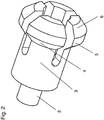
- a spring element 1 is in Fig. 2 represented in its equilibrium position without external forces. Its spring action is in the radial direction. To achieve the spring effect, it is slotted crosswise from one end, so that at the slotted end by radial pressure against the spring force a reduction of its diameter is made possible.
- the spring constant of the spring element 1 depends on the material used in addition to the depth of the slots. Material of the spring element 1 and depth and width of the slots are selected depending on the necessary insertion forces during insertion of the plug.
- a metallic material is selected, for example, a curable copper-beryllium alloy (CuBe) or hardenable spring steels. At low insertion forces, a technical plastic can be used.
- FIG. 3 The cross-sectional view of Fig. 3 (right figure, the left picture of the Fig. 3 shows a side view of the storage on a reduced scale and is mainly used for orientation on the position of the cutting plane) shows the same situation as that of Fig. 1 ,
- the plug flange 21 is still supported on the second cylindrical portion 3 of a spring element 1.
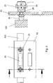
- Fig. 4 shows a situation in which the insertion process of the mating connector 30 has already started (plug-in direction 29). It can be seen that the bore 25 in the plug flange 21 already slides on the first conical region 4 of the spring element 1, whereby the slotted end of the spring element is compressed in the radial direction against the action of the spring force. As a result, the required for the mating operation counterforce is generated to the insertion force.
Landscapes
- Details Of Connecting Devices For Male And Female Coupling (AREA)
- Mechanical Coupling Of Light Guides (AREA)
Abstract
Description
- Die Erfindung betrifft eine gehäuseseitige Lagerung eines Steckers, welcher zur Kupplung mit einem Gegenstecker ausgebildet ist.
- Beim Zusammenstecken eines elektrischen, mehrpoligen Steckers mit dem entsprechenden Gegenstecker zu einer Steckverbindung werden typischerweise Führungsbolzen mit Druckfederelementen verwendet, um eine sichere elektrische Verbindung zuverlässig und schnell herzustellen. Probleme ergeben sich jedoch, wenn an der Steckerwand eines Gehäuses, welches elektronische Baugruppen aufnimmt, eine Vielzahl von Steckverbindungen vorhanden sind, z.B. bei der modularen Anordnung von elektronischen Baugruppen, wie sie typisch sind für eine elektronisch geschwenkte Radarantenne mit einer großen Zahl von einzelnen Sende- und Empfangsmodulen.
- Das dabei auftretende Problem besteht insbesondere darin, dass sich die Steckkräfte der einzelnen Steckverbindungen beim Zusammenstecken addieren und von dem Gehäuse bzw. einer Steckerwand an dem Gehäuse aufgenommen werden müssen. In dem oben genannten Beispiel einer Radarantenne von ca. 300 Blindsteckverbindungen auf einer Fläche von ca. 2m2 ergeben sich auf diese Weise Druckkräfte von 35.000 N an der Steckerwand.
- Der Erfindung liegt die Aufgabe zugrunde, eine gehäuseseitige Lagerung eines Steckers zu schaffen, mit der auch bei einer hohen Zahl von Steckverbindungen eine erhöhte Druckbelastung des Gehäuses aufgrund der Steckkräfte vermieden werden kann.
- Diese Aufgabe wird mit der Lagerung nach Anspruch 1 gelöst. Vorteilhafte Ausführungen sind Gegenstand von Unteransprüchen.
- Durch die erfindungsgemäße Lagerung werden keine Kräfte in die Gehäusestruktur impliziert. Während des Steckvorgangs gleitet der Stecker (an steckerseitigen Bohrungen) auf dem konischen Bereich eines radial wirkenden Federelements, wodurch die für den Kupplungsvorgang notwendige Gegenkraft zur Steckkraft erzeugt wird. Nach dem die Kupplung vollständig erfolgt ist, erreicht der Stecker einen zylindrischen Bereich des Federelements, wodurch die Axialkraft wieder aufgehoben wird.
- Da die Gehäusestruktur nicht mir Kräften beaufschlagt ist, können mit der Erfindung wesentlich Gewichts- und somit Kostenreduzierungen erzielt werden.
- Mit der Erfindung wird eine sichere und einfach zu handbabende Steckverbindung realisiert.
- Um mechanische Toleranzen auszugleichen, kann das Federelement an dem Gehäuse schwimmend befestigt werden, so dass sowohl horizontal als auch vertikal eine Bewegungsfreiheit (im Rahmen der vorgegebenen Toleranzen) besteht.
- Die Erfindung wird anhand eines konkreten Ausführungsbeispiels unter Bezugnahme auf Zeichnungen erläutert. Es zeigen:
- Fig. 1
- den grundsätzlichen Aufbau der erfindungsgemäßen Lagerung in 3D-Ansicht (vor Beginn des Steckvorgangs);
- Fig. 2
- ein erfindungsgemäßes Federelement in 3D-Ansicht;
- Fig. 3
- eine Schnittdarstellung der erfindungsgemäßen Lagerung mit einer Steckerposition entsprechend der in
Fig. 1 ; - Fig. 4
- eine Schnittdarstellung der erfindungsgemäßen Lagerung während des Steckvorgangs;
- Fig. 5
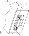
- eine 3D-Darstellung der erfindungsgemäßen Lagerung nach Abschluss des Steckvorgangs;
- Fig. 6
- eine Draufsicht auf die Situation gemäß
Fig. 5 . -
Fig. 1 zeigt den grundsätzlichen Aufbau der erfindungsgemäßen Lagerung. Mit Bezugsziffer 10 ist ein Ausschnitt aus der Steckerwand eines Gehäuses bezeichnet, an der modular eine größere Anzahl von Steckern 20 gelagert ist (von denen hier nur ein einzelner exemplarisch dargestellt ist). An der Steckerwand 10 ist der Stecker 20 mit zugehörigem Steckerflansch 21 vorhanden, die an jeweils einer Bohrung 25 am Flansch 21 auf zwei Federelemente 1 aufgesteckt sind. Die Zuführung des Steckergegenstücks erfolgt von der dem Betrachter abgewandten Seite der Gehäusewand 10 durch einen Durchbruch in der Gehäusewand (der entsprechende Durchbruch für den dem Stecker 20 benachbarten Stecker ist mit der Bezugsziffer 22 bezeichnet). Man sieht also inFig. 1 auf die Rückseite des Steckers. Die daran angeschlossenen Leitungen sind in dieser Prinzipdarstellung nicht eingezeichnet. Bei dem Stecker kann es sich insbesondere um einen mehrpoligen Stecker (z.B. mehr als 50 Kontakte) handeln, wobei die einzelnen Anschlüsse sowohl zur Strom/Spannungsversorgung als auch zur Leitung von Signalen vorgesehen sein können. - Ein Federelement 1 ist in
Fig. 2 in seiner Gleichgewichtslage ohne äußere Kräfte dargestellt. Seine Federwirkung besteht in radialer Richtung. Zur Erzielung der Federwirkung ist es von einem Ende her kreuzweise geschlitzt, so dass an dem geschlitzten Ende durch radialen Druck gegen die Federkraft eine Verringerung seines Durchmessers ermöglicht wird. Die Federkonstante des Federelements 1 hängt neben dem verwendeten Material von der Tiefe der Schlitze ab. Material des Federelements 1 sowie Tiefe und Breite der Schlitze werden abhängig von den notwendigen Steckkräften beim Einsteckvorgang der Stecker gewählt. Als Material für das Federelement wird insbesondere ein metallisches Material gewählt, z.B. eine aushärtbare Kupfer-Berylliumlegierung (CuBe) oder aushärtbare Federstähle. Bei niedrigen Steckkräften kann auch ein technischer Kunststoff eingesetzt werden. - Das Federelement 1 weist in Axialrichtung fünf verschiedene Bereiche auf:
- Einen ersten zylindrischen Bereich 2. Dieser Bereich dient zur Befestigung an der Gehäusewand 10 und wird zu diesem Zweck in eine gehäuseseitige Bohrung (Bezugsziffer 26 bezeichnet die entsprechende Bohrung für den dem Stecker 20 benachbarten Stecker) eingesteckt. Zum Ausgleich von Bautoleranzen kann die Lagerung des Federelements 1 in dieser Bohrung schwimmend erfolgen. Die entsprechenden Abmessungen von Bohrung und Bereich 2 am Federelement 1 werden dazu so gewählt, dass noch ausreichend Spiel vorhanden ist, und zwar bevorzugt sowohl in horizontaler wie auch in vertikaler Richtung. Eine Beweglichkeit des Steckers 20 in die dritte Raumrichtung (Steckrichtung) wird durch den benachbarten, zweiten, zylindrischen Abschnitt 3 des Federelements 1 erreicht, auf dem der Steckerflansch 21 bis zum Erreichen des konischen Abschnitts 4 des Federelements 1 frei gleiten kann. Die Befestigung des Federelements an der Bauteilwand erfolgt durch eine Schraube 9 (
Fig. 6 ) an der rückwärtigen Stirnseite (dem Betrachter inFig. 2 abgewandt) des Federelements 1. - Einen zweiten zylindrischen Bereich 3, in dieser Ausführung mit größerem Durchmesser als dem des ersten zylindrischen Bereichs 2, wobei Letzteres jedoch nicht zwingend ist. Auf diesem Bereich 3 des Federelements 1 stützt sich der Steckerflansch 21 vor dem Steckvorgang ab. Durchmesser von zweitem zylindrischen Bereich 3 und der entsprechenden Bohrung 25 im Steckerflansch werden bevorzugt so aufeinander abgestimmt, dass sich ein gewünschtes Spiel im Hinblick auf Bauteiltoleranzen ergibt.
- Einen ersten konischen Bereich 4, der einen Übergang zwischen dem zweiten zylindrischen Bereich 3 und dem sich daran anschießenden dritten zylindrischen Bereich 5 mit vergrößertem Durchmesser vermittelt. Er bildet eine - von der Gehäusewand 10 aus gesehen - ansteigende schiefe Ebene.
- Einen dritten zylindrischen Bereich 5. Dessen Durchmesser ist größer als der Durchmesser der Bohrung 25 am Flansch 21 des Steckers 20.
- Einen zweiten konischen Bereich 6 (Phase) am gehäusefernen Ende des Federelements 1. Die Steigung dieses zweiten konischen Bereichs 6 weist bezüglich der Steigung des ersten konischen Bereichs 4 ein entgegen gesetztes Vorzeichen auf. Die Beträge der beiden Steigungen werden unabhängig voneinander festgelegt, da die beiden konischen Bereiche 4 und 6 verschiedenen Zwecken dienen. Der zweite konusförmige Bereich 6 dient dazu, ein Aufstecken des Steckerflansches 21 auf das (bereits an der Gehäusewand 10 befestigte) Federelement 1 zu ermöglichen.
- Die Querschnittdarstellung der
Fig. 3 (rechte Abbildung; die linke Abbildung derFig. 3 zeigt eine Seitenansicht der Lagerung im verkleinerten Maßstab und dient vor allem zur Orientierung über die Lage der Schnittebene) zeigt die gleiche Situation wie die vonFig. 1 . Der Einsteckvorgang des Gegensteckers 30, welcher an einem Sende- oder Empfangsmodul 100 einer Antenne angeordnet ist, hat noch nicht begonnen. Der Steckerflansch 21 stützt sich noch an dem zweiten zylindrischen Bereich 3 eines Federelements 1 ab. -
Fig. 4 zeigt eine Situation, bei dem der Einsteckvorgang des Gegensteckers 30 bereits begonnen hat (Steckrichtung 29). Man erkennt, dass die Bohrung 25 im Steckerflansch 21 bereits auf dem ersten konischen Bereich 4 des Federelements 1 aufgleitet, wodurch das geschlitzte Ende des Federelements gegen die Wirkung der Federkraft in radialer Richtung gestaucht wird. Dadurch wird die für den Steckvorgang erforderliche Gegenkraft zur Steckkraft erzeugt. - Am Ende des konischen Bereichs 4 erreicht der Steckerflansch 21 den dritten zylindrischen Bereich 5 eines Federelements 1. Der Kupplungsvorgang von Stecker 20 und Gegenstecker 30 ist damit abgeschlossen und die Kraft in Axialrichtung ist vollständig aufgehoben. Der Steckerflansch 21 gleitet noch weiter, bis sich die in den
Fig. 5 und6 dargestellte Situation ergibt, in der der Steckerflansch 21 vollständig auf dem dritten zylindrischen Bereich 5 des Federelements 1 sitzt. Dies ist die Endposition, deren Überschreiten durch einen Anschlag (nicht dargestellt) an der Gehäusewand 10 ausgeschlossen wird.
Claims (3)
- Lagerung eines Steckers (20) an einem Gehäuse (10), welcher zur Kupplung mit einem Gegenstecker (30) ausgebildet ist, gekennzeichnet durch ein in seiner Radialrichtung federnd wirkendes, an dem Gehäuse (10) befestigtes und in eine steckerseitige Bohrung (25) gestecktes Federelement (1), wobei das Federelement (1) in Axialrichtung einen konischen Bereich (4) aufweist, der - in Steckrichtung (29) des Gegensteckers (30) gesehen - ansteigend ausgebildet ist, und an den sich ein zylinderförmiger Bereich (5) anschließt, wobei der Durchmesser des zylinderförmigen Bereichs (5) des Federelements (1) in dessen Gleichgewichtslage größer ist als der Durchmesser der steckerseitigen Bohrung (25).
- Lagerung nach Anspruch 1, dadurch gekennzeichnet, dass das Federelement (1) in zwei Raumrichtungen schwimmend in einer Bohrung (26) des Gehäuses (10) befestigt ist.
- Lagerung nach Anspruch 1 oder 2, dadurch gekennzeichnet, dass das Federelement (1) an seinem gehäusefernen Ende einen weiteren konischen Bereich (6) aufweist, der in Richtung auf das gehäuseferne Ende abfällt.
Applications Claiming Priority (1)
| Application Number | Priority Date | Filing Date | Title |
|---|---|---|---|
| DE201110012997 DE102011012997B3 (de) | 2011-03-04 | 2011-03-04 | Lagerung eines Steckers an einem Gehäuse |
Publications (2)
| Publication Number | Publication Date |
|---|---|
| EP2495828A1 true EP2495828A1 (de) | 2012-09-05 |
| EP2495828B1 EP2495828B1 (de) | 2017-02-08 |
Family
ID=45855446
Family Applications (1)
| Application Number | Title | Priority Date | Filing Date |
|---|---|---|---|
| EP12001253.9A Active EP2495828B1 (de) | 2011-03-04 | 2012-02-25 | Lagerung eines Steckers an einem Gehäuse |
Country Status (2)
| Country | Link |
|---|---|
| EP (1) | EP2495828B1 (de) |
| DE (1) | DE102011012997B3 (de) |
Cited By (1)
| Publication number | Priority date | Publication date | Assignee | Title |
|---|---|---|---|---|
| CN113394615A (zh) * | 2020-03-12 | 2021-09-14 | 范松皇家油墨厂 | 具有弹簧组件的厨房插入电源连接器组件 |
Families Citing this family (1)
| Publication number | Priority date | Publication date | Assignee | Title |
|---|---|---|---|---|
| CN113258318B (zh) * | 2021-07-06 | 2021-11-12 | 江苏长实基业电气科技有限公司 | 一种插板固定装置 |
Citations (5)
| Publication number | Priority date | Publication date | Assignee | Title |
|---|---|---|---|---|
| US5241451A (en) * | 1992-09-01 | 1993-08-31 | The Whitaker Corporation | Modular electronic assemblies using compressible electrical connectors |
| EP0648944A1 (de) * | 1993-10-13 | 1995-04-19 | TRW United-Carr GmbH & Co. KG | Verbindungselement aus Kunststoff |
| US5616052A (en) * | 1995-05-10 | 1997-04-01 | Hon Hai Precision Ind. Co., Ltd. | Screw mounting kit for use within connector |
| US20080145186A1 (en) * | 2006-12-15 | 2008-06-19 | Zuofeng Jin | Fastening device |
| US7607930B1 (en) * | 2008-08-05 | 2009-10-27 | Hon Hai Precision Ind. Co., Ltd. | Cable connector assembly having improved fixing member |
Family Cites Families (2)
| Publication number | Priority date | Publication date | Assignee | Title |
|---|---|---|---|---|
| US2871457A (en) * | 1956-10-26 | 1959-01-27 | Douglas Aircraft Co Inc | Mounting for electronic components |
| FR2879361A1 (fr) * | 2004-12-10 | 2006-06-16 | Radiall Sa | Ensemble de connexion comportant un support pourvu d'une ouverture et un boitier de connecteur monte sur ce support. |
-
2011
- 2011-03-04 DE DE201110012997 patent/DE102011012997B3/de active Active
-
2012
- 2012-02-25 EP EP12001253.9A patent/EP2495828B1/de active Active
Patent Citations (5)
| Publication number | Priority date | Publication date | Assignee | Title |
|---|---|---|---|---|
| US5241451A (en) * | 1992-09-01 | 1993-08-31 | The Whitaker Corporation | Modular electronic assemblies using compressible electrical connectors |
| EP0648944A1 (de) * | 1993-10-13 | 1995-04-19 | TRW United-Carr GmbH & Co. KG | Verbindungselement aus Kunststoff |
| US5616052A (en) * | 1995-05-10 | 1997-04-01 | Hon Hai Precision Ind. Co., Ltd. | Screw mounting kit for use within connector |
| US20080145186A1 (en) * | 2006-12-15 | 2008-06-19 | Zuofeng Jin | Fastening device |
| US7607930B1 (en) * | 2008-08-05 | 2009-10-27 | Hon Hai Precision Ind. Co., Ltd. | Cable connector assembly having improved fixing member |
Cited By (3)
| Publication number | Priority date | Publication date | Assignee | Title |
|---|---|---|---|---|
| CN113394615A (zh) * | 2020-03-12 | 2021-09-14 | 范松皇家油墨厂 | 具有弹簧组件的厨房插入电源连接器组件 |
| EP3878743A1 (de) * | 2020-03-12 | 2021-09-15 | Koninklijke Fabriek Inventum B.V. | Netzsteckeranordnung für bordkücheneinsatz mit federanordnungen |
| CN113394615B (zh) * | 2020-03-12 | 2024-04-12 | 范松皇家油墨厂 | 具有弹簧组件的厨房插入电源连接器组件 |
Also Published As
| Publication number | Publication date |
|---|---|
| EP2495828B1 (de) | 2017-02-08 |
| DE102011012997B3 (de) | 2012-08-23 |
Similar Documents
| Publication | Publication Date | Title |
|---|---|---|
| EP3011643B1 (de) | Halterahmen für steckverbindermodule | |
| DE102015211002B4 (de) | Verbinder mit einem Verbindergehäuse und einem Verbinderanschluss | |
| DE3537400A1 (de) | Gehaeuse fuer eine erweiterbare periphere interface-einheit | |
| DE69804149T2 (de) | Verriegelungshebelmechanismus für Verbinder | |
| DE102015015202A1 (de) | Steckverbinder und Stecksystem | |
| EP3132503B1 (de) | Isoliergehäuse einer elektrischen klemmvorrichtung | |
| EP1901402A1 (de) | Solarsteckverbinder mit verbesserten Rastmitteln | |
| DE2166754A1 (de) | Verschiebewerkzeug zum herstellen und trennen von steckkontaktverbindungen | |
| DE69014077T2 (de) | Elektrische Verbindereinrichtung und Verfahren zur Herstellung einer derartigen Verbindereinrichtung. | |
| DE102006012730B3 (de) | Befestigungssystem zum Befestigen eines Kabinenausstattungselements an einer Trägerstruktur eines Flugzeugs | |
| DE2323180A1 (de) | Verriegelung fuer einen elektrischen steckverbinder | |
| DE69104310T2 (de) | Elektrischer verbinder für prüfstand. | |
| EP2852003A1 (de) | Kontaktelement für einen Steckverbinder | |
| EP3358682A1 (de) | Elektrischer steckverbinder und elektrisches stecksystem | |
| DE4111054A1 (de) | Anschlussstecker | |
| DE69307103T2 (de) | Verfahren zur Befestigung eines beweglichen auf einen festen Verbinder und Befestigungsteil dafür | |
| DE102015211725B4 (de) | Verbinderanschluss und Verbinder hiermit | |
| EP2495828B1 (de) | Lagerung eines Steckers an einem Gehäuse | |
| DE10140153A1 (de) | Steckverbindung zum gleichzeitigen Verbinden mehrerer Koaxialkabel | |
| DE2628617A1 (de) | Befestigungsvorrichtung fuer steckfassungen | |
| DE2002425C3 (de) | Elektrischer Verbinder | |
| DE102007039064A1 (de) | Elektronisches Gerät und Leiterplatte mit Steckerleiste | |
| EP3785335A1 (de) | Steckverbinderteil einer steckverbindung | |
| DE102005061824B4 (de) | Computergehäuse | |
| EP3790121A1 (de) | Steckverbinder und stecksystem |
Legal Events
| Date | Code | Title | Description |
|---|---|---|---|
| PUAI | Public reference made under article 153(3) epc to a published international application that has entered the european phase |
Free format text: ORIGINAL CODE: 0009012 |
|
| AK | Designated contracting states |
Kind code of ref document: A1 Designated state(s): AL AT BE BG CH CY CZ DE DK EE ES FI FR GB GR HR HU IE IS IT LI LT LU LV MC MK MT NL NO PL PT RO RS SE SI SK SM TR |
|
| AX | Request for extension of the european patent |
Extension state: BA ME |
|
| 17P | Request for examination filed |
Effective date: 20121127 |
|
| RAP1 | Party data changed (applicant data changed or rights of an application transferred) |
Owner name: AIRBUS DEFENCE AND SPACE GMBH |
|
| RAP1 | Party data changed (applicant data changed or rights of an application transferred) |
Owner name: AIRBUS DS ELECTRONICS AND BORDER SECURITY GMBH |
|
| RIC1 | Information provided on ipc code assigned before grant |
Ipc: F16B 5/06 20060101ALI20160822BHEP Ipc: H01R 13/74 20060101AFI20160822BHEP Ipc: H01R 13/631 20060101ALN20160822BHEP |
|
| GRAP | Despatch of communication of intention to grant a patent |
Free format text: ORIGINAL CODE: EPIDOSNIGR1 |
|
| RIC1 | Information provided on ipc code assigned before grant |
Ipc: H01R 13/631 20060101ALN20161013BHEP Ipc: H01R 13/74 20060101AFI20161013BHEP Ipc: F16B 5/06 20060101ALI20161013BHEP |
|
| GRAS | Grant fee paid |
Free format text: ORIGINAL CODE: EPIDOSNIGR3 |
|
| INTG | Intention to grant announced |
Effective date: 20161026 |
|
| GRAA | (expected) grant |
Free format text: ORIGINAL CODE: 0009210 |
|
| AK | Designated contracting states |
Kind code of ref document: B1 Designated state(s): AL AT BE BG CH CY CZ DE DK EE ES FI FR GB GR HR HU IE IS IT LI LT LU LV MC MK MT NL NO PL PT RO RS SE SI SK SM TR |
|
| REG | Reference to a national code |
Ref country code: GB Ref legal event code: FG4D Free format text: NOT ENGLISH |
|
| REG | Reference to a national code |
Ref country code: CH Ref legal event code: EP Ref country code: AT Ref legal event code: REF Ref document number: 867229 Country of ref document: AT Kind code of ref document: T Effective date: 20170215 |
|
| REG | Reference to a national code |
Ref country code: FR Ref legal event code: PLFP Year of fee payment: 6 |
|
| REG | Reference to a national code |
Ref country code: IE Ref legal event code: FG4D Free format text: LANGUAGE OF EP DOCUMENT: GERMAN |
|
| REG | Reference to a national code |
Ref country code: DE Ref legal event code: R096 Ref document number: 502012009485 Country of ref document: DE |
|
| REG | Reference to a national code |
Ref country code: LT Ref legal event code: MG4D |
|
| REG | Reference to a national code |
Ref country code: NL Ref legal event code: MP Effective date: 20170208 |
|
| PG25 | Lapsed in a contracting state [announced via postgrant information from national office to epo] |
Ref country code: LT Free format text: LAPSE BECAUSE OF FAILURE TO SUBMIT A TRANSLATION OF THE DESCRIPTION OR TO PAY THE FEE WITHIN THE PRESCRIBED TIME-LIMIT Effective date: 20170208 Ref country code: NO Free format text: LAPSE BECAUSE OF FAILURE TO SUBMIT A TRANSLATION OF THE DESCRIPTION OR TO PAY THE FEE WITHIN THE PRESCRIBED TIME-LIMIT Effective date: 20170508 Ref country code: FI Free format text: LAPSE BECAUSE OF FAILURE TO SUBMIT A TRANSLATION OF THE DESCRIPTION OR TO PAY THE FEE WITHIN THE PRESCRIBED TIME-LIMIT Effective date: 20170208 Ref country code: GR Free format text: LAPSE BECAUSE OF FAILURE TO SUBMIT A TRANSLATION OF THE DESCRIPTION OR TO PAY THE FEE WITHIN THE PRESCRIBED TIME-LIMIT Effective date: 20170509 Ref country code: HR Free format text: LAPSE BECAUSE OF FAILURE TO SUBMIT A TRANSLATION OF THE DESCRIPTION OR TO PAY THE FEE WITHIN THE PRESCRIBED TIME-LIMIT Effective date: 20170208 |
|
| REG | Reference to a national code |
Ref country code: DE Ref legal event code: R082 Ref document number: 502012009485 Country of ref document: DE Representative=s name: LIFETECH IP SPIES & BEHRNDT PATENTANWAELTE PAR, DE Ref country code: DE Ref legal event code: R081 Ref document number: 502012009485 Country of ref document: DE Owner name: HENSOLDT SENSORS GMBH, DE Free format text: FORMER OWNER: AIRBUS DS ELECTRONICS AND BORDER SECURITY GMBH, 82024 TAUFKIRCHEN, DE |
|
| PG25 | Lapsed in a contracting state [announced via postgrant information from national office to epo] |
Ref country code: NL Free format text: LAPSE BECAUSE OF FAILURE TO SUBMIT A TRANSLATION OF THE DESCRIPTION OR TO PAY THE FEE WITHIN THE PRESCRIBED TIME-LIMIT Effective date: 20170208 Ref country code: PT Free format text: LAPSE BECAUSE OF FAILURE TO SUBMIT A TRANSLATION OF THE DESCRIPTION OR TO PAY THE FEE WITHIN THE PRESCRIBED TIME-LIMIT Effective date: 20170608 Ref country code: LV Free format text: LAPSE BECAUSE OF FAILURE TO SUBMIT A TRANSLATION OF THE DESCRIPTION OR TO PAY THE FEE WITHIN THE PRESCRIBED TIME-LIMIT Effective date: 20170208 Ref country code: RS Free format text: LAPSE BECAUSE OF FAILURE TO SUBMIT A TRANSLATION OF THE DESCRIPTION OR TO PAY THE FEE WITHIN THE PRESCRIBED TIME-LIMIT Effective date: 20170208 Ref country code: ES Free format text: LAPSE BECAUSE OF FAILURE TO SUBMIT A TRANSLATION OF THE DESCRIPTION OR TO PAY THE FEE WITHIN THE PRESCRIBED TIME-LIMIT Effective date: 20170208 Ref country code: SE Free format text: LAPSE BECAUSE OF FAILURE TO SUBMIT A TRANSLATION OF THE DESCRIPTION OR TO PAY THE FEE WITHIN THE PRESCRIBED TIME-LIMIT Effective date: 20170208 Ref country code: BG Free format text: LAPSE BECAUSE OF FAILURE TO SUBMIT A TRANSLATION OF THE DESCRIPTION OR TO PAY THE FEE WITHIN THE PRESCRIBED TIME-LIMIT Effective date: 20170508 |
|
| REG | Reference to a national code |
Ref country code: CH Ref legal event code: PL |
|
| PG25 | Lapsed in a contracting state [announced via postgrant information from national office to epo] |
Ref country code: IT Free format text: LAPSE BECAUSE OF FAILURE TO SUBMIT A TRANSLATION OF THE DESCRIPTION OR TO PAY THE FEE WITHIN THE PRESCRIBED TIME-LIMIT Effective date: 20170208 Ref country code: SK Free format text: LAPSE BECAUSE OF FAILURE TO SUBMIT A TRANSLATION OF THE DESCRIPTION OR TO PAY THE FEE WITHIN THE PRESCRIBED TIME-LIMIT Effective date: 20170208 Ref country code: LI Free format text: LAPSE BECAUSE OF NON-PAYMENT OF DUE FEES Effective date: 20170228 Ref country code: CZ Free format text: LAPSE BECAUSE OF FAILURE TO SUBMIT A TRANSLATION OF THE DESCRIPTION OR TO PAY THE FEE WITHIN THE PRESCRIBED TIME-LIMIT Effective date: 20170208 Ref country code: EE Free format text: LAPSE BECAUSE OF FAILURE TO SUBMIT A TRANSLATION OF THE DESCRIPTION OR TO PAY THE FEE WITHIN THE PRESCRIBED TIME-LIMIT Effective date: 20170208 Ref country code: CH Free format text: LAPSE BECAUSE OF NON-PAYMENT OF DUE FEES Effective date: 20170228 Ref country code: RO Free format text: LAPSE BECAUSE OF FAILURE TO SUBMIT A TRANSLATION OF THE DESCRIPTION OR TO PAY THE FEE WITHIN THE PRESCRIBED TIME-LIMIT Effective date: 20170208 |
|
| REG | Reference to a national code |
Ref country code: DE Ref legal event code: R097 Ref document number: 502012009485 Country of ref document: DE |
|
| REG | Reference to a national code |
Ref country code: IE Ref legal event code: MM4A |
|
| PG25 | Lapsed in a contracting state [announced via postgrant information from national office to epo] |
Ref country code: PL Free format text: LAPSE BECAUSE OF FAILURE TO SUBMIT A TRANSLATION OF THE DESCRIPTION OR TO PAY THE FEE WITHIN THE PRESCRIBED TIME-LIMIT Effective date: 20170208 Ref country code: MC Free format text: LAPSE BECAUSE OF FAILURE TO SUBMIT A TRANSLATION OF THE DESCRIPTION OR TO PAY THE FEE WITHIN THE PRESCRIBED TIME-LIMIT Effective date: 20170208 Ref country code: DK Free format text: LAPSE BECAUSE OF FAILURE TO SUBMIT A TRANSLATION OF THE DESCRIPTION OR TO PAY THE FEE WITHIN THE PRESCRIBED TIME-LIMIT Effective date: 20170208 Ref country code: SM Free format text: LAPSE BECAUSE OF FAILURE TO SUBMIT A TRANSLATION OF THE DESCRIPTION OR TO PAY THE FEE WITHIN THE PRESCRIBED TIME-LIMIT Effective date: 20170208 |
|
| PLBE | No opposition filed within time limit |
Free format text: ORIGINAL CODE: 0009261 |
|
| STAA | Information on the status of an ep patent application or granted ep patent |
Free format text: STATUS: NO OPPOSITION FILED WITHIN TIME LIMIT |
|
| PG25 | Lapsed in a contracting state [announced via postgrant information from national office to epo] |
Ref country code: LU Free format text: LAPSE BECAUSE OF NON-PAYMENT OF DUE FEES Effective date: 20170225 |
|
| 26N | No opposition filed |
Effective date: 20171109 |
|
| REG | Reference to a national code |
Ref country code: BE Ref legal event code: MM Effective date: 20170228 |
|
| REG | Reference to a national code |
Ref country code: FR Ref legal event code: PLFP Year of fee payment: 7 |
|
| PG25 | Lapsed in a contracting state [announced via postgrant information from national office to epo] |
Ref country code: IE Free format text: LAPSE BECAUSE OF NON-PAYMENT OF DUE FEES Effective date: 20170225 Ref country code: SI Free format text: LAPSE BECAUSE OF FAILURE TO SUBMIT A TRANSLATION OF THE DESCRIPTION OR TO PAY THE FEE WITHIN THE PRESCRIBED TIME-LIMIT Effective date: 20170208 |
|
| REG | Reference to a national code |
Ref country code: AT Ref legal event code: MM01 Ref document number: 867229 Country of ref document: AT Kind code of ref document: T Effective date: 20170225 |
|
| PG25 | Lapsed in a contracting state [announced via postgrant information from national office to epo] |
Ref country code: BE Free format text: LAPSE BECAUSE OF NON-PAYMENT OF DUE FEES Effective date: 20170228 Ref country code: AT Free format text: LAPSE BECAUSE OF NON-PAYMENT OF DUE FEES Effective date: 20170225 |
|
| PG25 | Lapsed in a contracting state [announced via postgrant information from national office to epo] |
Ref country code: MT Free format text: LAPSE BECAUSE OF FAILURE TO SUBMIT A TRANSLATION OF THE DESCRIPTION OR TO PAY THE FEE WITHIN THE PRESCRIBED TIME-LIMIT Effective date: 20170208 |
|
| PG25 | Lapsed in a contracting state [announced via postgrant information from national office to epo] |
Ref country code: HU Free format text: LAPSE BECAUSE OF FAILURE TO SUBMIT A TRANSLATION OF THE DESCRIPTION OR TO PAY THE FEE WITHIN THE PRESCRIBED TIME-LIMIT; INVALID AB INITIO Effective date: 20120225 |
|
| PG25 | Lapsed in a contracting state [announced via postgrant information from national office to epo] |
Ref country code: CY Free format text: LAPSE BECAUSE OF NON-PAYMENT OF DUE FEES Effective date: 20170208 |
|
| PG25 | Lapsed in a contracting state [announced via postgrant information from national office to epo] |
Ref country code: MK Free format text: LAPSE BECAUSE OF FAILURE TO SUBMIT A TRANSLATION OF THE DESCRIPTION OR TO PAY THE FEE WITHIN THE PRESCRIBED TIME-LIMIT Effective date: 20170208 |
|
| PG25 | Lapsed in a contracting state [announced via postgrant information from national office to epo] |
Ref country code: TR Free format text: LAPSE BECAUSE OF FAILURE TO SUBMIT A TRANSLATION OF THE DESCRIPTION OR TO PAY THE FEE WITHIN THE PRESCRIBED TIME-LIMIT Effective date: 20170208 |
|
| PG25 | Lapsed in a contracting state [announced via postgrant information from national office to epo] |
Ref country code: AL Free format text: LAPSE BECAUSE OF FAILURE TO SUBMIT A TRANSLATION OF THE DESCRIPTION OR TO PAY THE FEE WITHIN THE PRESCRIBED TIME-LIMIT Effective date: 20170208 Ref country code: IS Free format text: LAPSE BECAUSE OF FAILURE TO SUBMIT A TRANSLATION OF THE DESCRIPTION OR TO PAY THE FEE WITHIN THE PRESCRIBED TIME-LIMIT Effective date: 20170608 |
|
| PGFP | Annual fee paid to national office [announced via postgrant information from national office to epo] |
Ref country code: GB Payment date: 20260219 Year of fee payment: 15 |
|
| PGFP | Annual fee paid to national office [announced via postgrant information from national office to epo] |
Ref country code: DE Payment date: 20260217 Year of fee payment: 15 |
|
| PGFP | Annual fee paid to national office [announced via postgrant information from national office to epo] |
Ref country code: FR Payment date: 20260223 Year of fee payment: 15 |