EP2495343A1 - Dispositif de refroidissement à jet de gaz pour four de recuit continu - Google Patents
Dispositif de refroidissement à jet de gaz pour four de recuit continu Download PDFInfo
- Publication number
- EP2495343A1 EP2495343A1 EP10826922A EP10826922A EP2495343A1 EP 2495343 A1 EP2495343 A1 EP 2495343A1 EP 10826922 A EP10826922 A EP 10826922A EP 10826922 A EP10826922 A EP 10826922A EP 2495343 A1 EP2495343 A1 EP 2495343A1
- Authority
- EP
- European Patent Office
- Prior art keywords
- steel strip
- gas
- headers
- pressure
- nozzles
- Prior art date
- Legal status (The legal status is an assumption and is not a legal conclusion. Google has not performed a legal analysis and makes no representation as to the accuracy of the status listed.)
- Granted
Links
- 238000001816 cooling Methods 0.000 title claims abstract description 102
- 238000000137 annealing Methods 0.000 title claims abstract description 23
- 229910000831 Steel Inorganic materials 0.000 claims abstract description 208
- 239000010959 steel Substances 0.000 claims abstract description 208
- 238000006073 displacement reaction Methods 0.000 claims abstract description 7
- 239000007789 gas Substances 0.000 claims description 78
- UFHFLCQGNIYNRP-UHFFFAOYSA-N Hydrogen Chemical compound [H][H] UFHFLCQGNIYNRP-UHFFFAOYSA-N 0.000 claims description 33
- 239000001257 hydrogen Substances 0.000 claims description 18
- 229910052739 hydrogen Inorganic materials 0.000 claims description 18
- 239000000203 mixture Substances 0.000 claims description 6
- 238000009826 distribution Methods 0.000 abstract description 14
- 239000000112 cooling gas Substances 0.000 description 10
- 230000000694 effects Effects 0.000 description 7
- 238000000034 method Methods 0.000 description 7
- 239000002826 coolant Substances 0.000 description 6
- XLYOFNOQVPJJNP-UHFFFAOYSA-N water Substances O XLYOFNOQVPJJNP-UHFFFAOYSA-N 0.000 description 6
- 238000002474 experimental method Methods 0.000 description 5
- 230000000052 comparative effect Effects 0.000 description 4
- 230000007246 mechanism Effects 0.000 description 4
- 230000014759 maintenance of location Effects 0.000 description 3
- 238000010791 quenching Methods 0.000 description 3
- 230000000171 quenching effect Effects 0.000 description 3
- 230000001603 reducing effect Effects 0.000 description 3
- 230000011218 segmentation Effects 0.000 description 3
- 238000002791 soaking Methods 0.000 description 3
- 238000011144 upstream manufacturing Methods 0.000 description 3
- 230000007423 decrease Effects 0.000 description 2
- 238000010586 diagram Methods 0.000 description 2
- 238000010438 heat treatment Methods 0.000 description 2
- HCHKCACWOHOZIP-UHFFFAOYSA-N Zinc Chemical compound [Zn] HCHKCACWOHOZIP-UHFFFAOYSA-N 0.000 description 1
- 238000009825 accumulation Methods 0.000 description 1
- 230000032683 aging Effects 0.000 description 1
- 230000003247 decreasing effect Effects 0.000 description 1
- 238000011161 development Methods 0.000 description 1
- 230000018109 developmental process Effects 0.000 description 1
- 238000005516 engineering process Methods 0.000 description 1
- 238000000605 extraction Methods 0.000 description 1
- 238000005246 galvanizing Methods 0.000 description 1
- 239000000463 material Substances 0.000 description 1
- 238000005259 measurement Methods 0.000 description 1
- 239000002184 metal Substances 0.000 description 1
- 229910052751 metal Inorganic materials 0.000 description 1
- 238000012544 monitoring process Methods 0.000 description 1
- 238000009828 non-uniform distribution Methods 0.000 description 1
- 230000001590 oxidative effect Effects 0.000 description 1
- 238000005192 partition Methods 0.000 description 1
- 238000006748 scratching Methods 0.000 description 1
- 230000002393 scratching effect Effects 0.000 description 1
- 238000012546 transfer Methods 0.000 description 1
- 229910052725 zinc Inorganic materials 0.000 description 1
- 239000011701 zinc Substances 0.000 description 1
Images


Classifications
-
- F—MECHANICAL ENGINEERING; LIGHTING; HEATING; WEAPONS; BLASTING
- F27—FURNACES; KILNS; OVENS; RETORTS
- F27D—DETAILS OR ACCESSORIES OF FURNACES, KILNS, OVENS, OR RETORTS, IN SO FAR AS THEY ARE OF KINDS OCCURRING IN MORE THAN ONE KIND OF FURNACE
- F27D9/00—Cooling of furnaces or of charges therein
-
- C—CHEMISTRY; METALLURGY
- C21—METALLURGY OF IRON
- C21D—MODIFYING THE PHYSICAL STRUCTURE OF FERROUS METALS; GENERAL DEVICES FOR HEAT TREATMENT OF FERROUS OR NON-FERROUS METALS OR ALLOYS; MAKING METAL MALLEABLE, e.g. BY DECARBURISATION OR TEMPERING
- C21D9/00—Heat treatment, e.g. annealing, hardening, quenching or tempering, adapted for particular articles; Furnaces therefor
- C21D9/52—Heat treatment, e.g. annealing, hardening, quenching or tempering, adapted for particular articles; Furnaces therefor for wires; for strips ; for rods of unlimited length
- C21D9/54—Furnaces for treating strips or wire
- C21D9/56—Continuous furnaces for strip or wire
- C21D9/573—Continuous furnaces for strip or wire with cooling
- C21D9/5735—Details
-
- F—MECHANICAL ENGINEERING; LIGHTING; HEATING; WEAPONS; BLASTING
- F27—FURNACES; KILNS; OVENS; RETORTS
- F27B—FURNACES, KILNS, OVENS, OR RETORTS IN GENERAL; OPEN SINTERING OR LIKE APPARATUS
- F27B9/00—Furnaces through which the charge is moved mechanically, e.g. of tunnel type; Similar furnaces in which the charge moves by gravity
- F27B9/28—Furnaces through which the charge is moved mechanically, e.g. of tunnel type; Similar furnaces in which the charge moves by gravity for treating continuous lengths of work
Definitions
- the present invention relates to a gas-jet cooling apparatus for a continuous annealing furnace.
- a process of continuously heating, soaking, cooling, and if necessary, over ageing a steel strip is performed.
- heating temperature and soaking time important, but also uniform quenching of the steel strip is important.
- Development of high tensile steel used as an automobile material has progressed in recent years.
- processes for quenching a steel strip from an annealing temperature in the range of 900 to 800°C to a temperature in the range of about 300 to 150°C have been developed.
- a cooling method using a gas as the coolant is also used.
- the cooling speed of this method is lower than those of the water cooling method and the roll cooling method described above, this method enables more uniform cooling in the width direction of a steel strip.
- PTL 1 discloses an apparatus including a box-shaped header and long gas discharge nozzles attached to the header. The ends of the nozzles are disposed as close as possible to a steel strip, so that the heat transfer coefficient and the cooling speed are increased.
- PTL 2 discloses an apparatus that increases the cooling efficiency by using hydrogen.
- a gas having a uniform hydrogen concentration (in the range of 20 to 80%) is introduced into the header. Because the temperature distribution in the width direction of the steel strip is not uniform due to influences of gas flow, a furnace wall, the header structure, and the like, the temperature distribution in the width direction does not become uniform if cooling is performed in the same manner in the width direction of the steel strip, and thereby the quality of the steel strip becomes non-uniform. Moreover, because fluttering of the steel strip occurs, the speed at which gas is discharged is limited (within the range of 100 to 190 m/s).
- An object of the present invention is to provide a gas-jet cooling apparatus for a continuous annealing furnace that reduces non-uniformity in the temperature distribution in the width direction of a steel strip, reduces fluttering of the steel strip when the gas is discharged at a high speed, and thereby realizes efficient cooling.
- the gist of the present invention is as follows.
- the present invention even if the gas is discharged from the nozzles at a high speed, retention of gas is prevented and circulation of gas in the cooling zone is promoted, whereby the cooling performance of the nozzles is maximally used and efficient cooling is achieved. Moreover, scratching of a steel strip due to fluttering and non-uniformity in the quality of the steel strip in the width direction are prevented, so that a steel strip having a uniform quality and a beautiful appearance can be produced.
- a gas-jet cooling apparatus according to an embodiment of the present invention is disposed in a cooling zone of a continuous steel strip annealing furnace will be described in detail.
- percentage used to describe the composition of the furnace gas or a gas introduced into the pressure header and the like is volume percent.
- Fig. 3 is a longitudinal sectional view illustrating the main part of a cooling zone of a continuous steel strip annealing furnace including a gas-jet cooling apparatus according to an embodiment of the present invention.
- Fig. 3 illustrates a cooling zone 1, rollers 2 to 4, press rollers 5 and 6, gas-jet cooling apparatuses 7 to 10, pressure headers 11, main headers 17, blower fans 13 to 16, and a steel strip S.
- the cooling zone 1 includes a single temperature control zone or a plurality of temperature control zones. In the present embodiment, there are four temperature control zones, and the gas-jet cooling apparatuses 7 to 10 are disposed in respective zones.
- a cooling gas (coolant) is blown by the blower fans 13 to 16 to the main headers 17 and then to the pressure headers 11.
- Fig. 1 is a longitudinal sectional view illustrating the arrangement of the pressure headers 11 and nozzles 12 in the gas-jet cooling apparatus.
- the pressure headers 11 are serially arranged along the movement direction of the steel strip on each of the front and back sides of the steel strip.
- the nozzles 12, which protrude from each of the pressure headers 11, are arranged along the width direction of the steel strip at a constant pitch on a side of the pressure headers 11 that faces the steel strip.
- the pressure headers 11 have a tubular shape.
- the pressure headers 11 extend in the width direction of the steel strip and each have a length that is larger than the width of the steel strip.
- a non-oxidizing cooling gas (such as N 2 , H 2 , or a mixture gas composed of these) is blown toward the steel strip S from the nozzles 12.
- the cooling gas is usually blown by using the blower fans 13 to 16.
- a furnace gas may be internally circulated or a gas may be drawn from the outside.
- a steel strip having a temperature in the range of about 900 to 600°C after being annealed is usually cooled to a temperature in the range of about 550 to 200°C.
- the nozzles 12 have a tapered protruding structure such that the area of the bottom opening of the nozzle is larger than the area of the end opening of the nozzle.
- a tapered protruding structure such that the area of the bottom opening of the nozzle is larger than the area of the end opening of the nozzle.
- the protruding length 1 of the nozzle be equal to or greater than 20 mm and equal to or smaller than 120 mm. If the protruding length is smaller than 20 mm, the cooling effect is reduced due to accumulation of heat between the steel strip and the pressure header. If the protruding length is greater than 120 mm, the pressure loss is large and only a small amount of gas can be discharged. It is preferable that the protruding length be in the range of 40 to 100 mm.
- Fig. 2 is a front view illustrating the arrangement of openings of the nozzles 12.
- the pressure headers 11 are arranged at a constant pitch L along the longitudinal direction of the steel strip on each of the front and back sides of the steel strip. Therefore, the nozzles 12 are also arranged at the constant pitch L along the longitudinal direction of the steel strip. Moreover, the nozzles 12 of each pressure headers 11 are arranged at a constant pitch W along the width direction of the steel strip.
- the nozzles 12 are arranged in a staggered manner such that the positions of the nozzles 12 of one of the pressure headers 11 along the width direction of the steel strip are located between the positions of the nozzles 12 of the other one of the pressure headers 11 that is immediately upstream of the one of the pressure headers 11 in the longitudinal direction of the steel strip. That is, in the case of the front-side nozzle positions along the longitudinal direction of the steel strip illustrated by solid lines in Fig.
- the state in which the nozzles are "arranged in a staggered manner" refers to a state in which the nozzle positions immediately upstream in the longitudinal direction of the steel strip are displaced in the width direction of the steel strip so as to be located between the nozzles 12.
- the state refers to a state in which the nozzle positions immediately upstream in the longitudinal direction of the steel strip are displaced in the width direction of the steel strip so as to be located between the nozzles 12. It is generally known that the range on which a single nozzle acts is optimized and the cooling performance is high when the nozzles 12 are arranged in such a staggered manner.
- the present inventors have found that vibration of the steel strip can be reduced if the pressure headers 11 on the front side of the steel strip and the pressure headers 11 on the back side of the steel strip are arranged so as to be displaced from each other in the longitudinal direction of the steel strip, i.e., if the nozzles 12 on the front side of the steel strip and the nozzles 12 on the back side of the steel strip are arranged so as to be displaced from each other in the longitudinal direction of the steel strip. Vibration of the steel strip is caused by a turbulent flow of gas discharged at a high speed from the nozzle, turbulence of an associated flow of gas that flows along a steel strip whose shape is unstable, or the like.
- the present inventors have found that the effect described above is produced if the positions of the pressure headers 11 on the front and back sides of the steel strip are displaced in the longitudinal direction of the steel strip such that a distance (L1 in Fig. 2 ), in the longitudinal direction of the steel strip, between the pressure headers on the front side of the steel strip and the pressure headers on the back side of the steel strip is equal to or greater than 1/3 and equal to or smaller than 2/3 of the pitch L of the pressure headers.
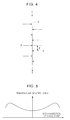
- Fig. 4 is a conceptual diagram illustrating the relationship between forces that are applied to the steel strip due to the nozzles of the pressure headers of the gas-jet cooling apparatus.
- a rotation moment PZ acts on the steel strip and a force to bend the steel strip S in the longitudinal direction acts on the steel strip S, where P is a pressure generated when a gas collides with the steel strip S, T is the tension of the steel strip S, and Z is the distance between the nozzles that are located closest to each other in the longitudinal direction of the steel strip.
- the tension T of the steel strip generates a restoring force to straighten the steel strip. It is assumed that the vibration is reduced by the restoring force.
- the present inventors have found that non-uniformity in the temperature distribution is prevented and the steel strip is provided with uniform quality if the positions of the nozzles on the front and back sides of the steel strip are displaced in the width direction of the steel strip.
- Non-uniformity in the temperature distribution is reduced when the displacement amount (W1 in Fig. 2 ) between a nozzle group on one of the front and back sides of the steel strip and a nozzle group on the other of the front and back sides of the steel strip in the width direction of the steel strip is equal to or greater than 1/6 and equal to or smaller than 1/3 of the nozzle pitch W (see Fig. 2 ) in the width direction of the steel strip. If the displacement amount (W1 in Fig.
- each main header 17 be segmented into three or more and seven or less segmented main headers in the width direction of the steel strip and that each pressure header 11 be segmented into three or more and seven or less segmented pressure headers so as to correspond in number to the segmented main headers.
- the gas can be supplied from the segmented main headers to the segmented pressure headers that correspond to the segmented main headers in the width direction, i.e., that are located at the same positions with respect to the width direction.
- the header pressure of each segment of the main header 17 can be adjusted.
- the steel strip When the steel strip is warped and a cross-section of the steel strip is C-shaped in the width direction, i.e. when so-called C-shaped warping occurs, the steel strip has a temperature distribution in the width direction such that a middle part of the steel strip has a lower temperature as illustrated in Fig. 5 , because the cooling gas is concentrated in the middle part of the steel strip.
- the temperature of the steel strip is adjusted as follows: the main header 17 is segmented in the width direction of the steel strip; the pressure header 11 is segmented in the width direction of the steel strip so as to correspond to the segmentation of the main header 17; the pressure of the main header 17 is adjusted in the width direction of the steel strip; and the amount of gas discharged from the pressure header 11 (header pressure) is changed in the width direction.
- the number of segments of the header in the width direction of the steel strip is smaller than three, the temperature distribution cannot be made uniform. Although the temperature distribution was improved when the number of segments was increased up to seven, the temperature distribution was not improved further when the number of segments was larger than seven. Therefore, it is preferable that the number of segments be equal to or smaller than seven with consideration of the equipment cost.
- the furnace gas in the cooling zone of the continuous annealing furnace can be used as a cooling gas that is introduced into the pressure headers 11.
- the hydrogen concentration of the furnace gas in the cooling zone is usually set in the range of about 5 to 20% to produce reducing atmosphere.
- the cooling performance can be improved by using a cooling gas having a hydrogen concentration higher than that of the furnace gas in the cooling zone.
- the hydrogen concentration of the cooling gas introduced into the pressure headers 11 can be increased by introducing a gas having a hydrogen concentration higher that of the furnace gas into the main header 17. The effect of improving the cooling performance is not produced if the hydrogen concentration of a gas that includes hydrogen gas with a concentration higher than that of the furnace gas in the cooling zone is lower than 30%.
- the gas introduced into the main header 17, which includes hydrogen gas with a concentration higher than that of the furnace gas in the cooling zone be hydrogen gas or a nitrogen-hydrogen mixture gas including hydrogen gas with a concentration equal to or higher than 30 volume percent.
- uniformity in the temperature in the width direction of the steel strip can be improved further by allowing hydrogen gas or a nitrogen-hydrogen mixture gas having a hydrogen concentration equal to or higher than 30% to be introduced into each main header 17 and by allowing the flow rate of the gas to be adjusted.
- Fig. 6 illustrates a gas-jet cooling apparatus according to an embodiment in which the main header and the pressure headers are each segmented into five segments in the width direction of the steel strip and that allows adjustment of the gas pressure and the amount of hydrogen gas for each of segmented headers, part (a) illustrating a front view and part (b) illustrating a side view.
- the pressure headers are disposed on each of the front and back sides of the steel strip. For convenience of description, Fig. 6 illustrates only three pressure headers on one of the sides.
- each pressure header 11, on which nozzles are disposed is segmented into five segments in the width direction of the steel strip as illustrated by broken lines.
- Segmented pressure headers 11-1 to 11-5 are formed by the segmentation.
- the segmented pressure headers of the pressure headers 11 are partitioned from each other.
- Segmented main headers 17-1 to 17-5 the number of which is the same as the number of the segments of the pressure header 11, are disposed behind the segmented pressure headers 11-1 to 11-5, respectively, and extend in the vertical direction.
- the segmented main headers 17-1 to 17-5 are connected to the groups of the segmented pressure headers 11-1 to 11-5, respectively.
- Atmospheric gas inlet pipes 18-1 to 18-5 for introducing the furnace gas (atmospheric gas) in the cooling zone therethrough and high-concentration hydrogen gas inlet pipe 19-1 to 19-5 for introducing a gas including hydrogen gas with a concentration higher than that of the furnace gas therethrough are connected to the segmented main headers 17-1 to 17-5, respectively.
- the atmospheric gas inlet pipes 18-1 to 18-5 and the high-concentration hydrogen gas inlet pipes 19-1 to 19-5 respectively include mechanisms 20-1 to 20-5 and 21-1 to 21-5 for adjusting the degree of opening or the pressure.
- the internal pressure and the hydrogen concentration in each of the segmented main headers 17-1 to 17-5 can be adjusted by operating a corresponding one of the mechanisms 20-1 to 20-5 and 21-1 to 21-5 for adjusting the degree of opening or the pressure.
- the gas that has been introduced into the segmented main headers 17-1 to 17-5 is guided to the segmented pressure headers 11-1 to 11-5 that are connected to the headers, respectively.
- the cooling performance of the pressure headers 11 in the width direction of the steel strip can be changed and the temperature distribution in the width direction of the steel strip can be adjusted.
- the segmented pressure headers of the pressure headers 11 are partitioned from each other. However, partitions between the segmented pressure headers need not be formed.
- the temperature distribution in the width direction of the steel strip may be adjusted by changing one or both of the internal pressure and the hydrogen concentration in each of the segmented main headers 17-1 to 17-5 and thereby changing the cooling performance of the pressure headers 11 in the width direction of the steel strip.
- the pressure headers and the main headers on the other one the front and back sides of the steel strip have structures the same as those described above.
- the main headers on the other side and the segmented main headers 17-1 to 17-5 that correspond in position to the main headers in the width direction are connected to each other through header pipes (not shown) that extend around a side edge of the steel strip. With such a structure, the effect described above is produced on the front and back sides of the steel strip.
- Nozzles arranged in a staggered manner and having high cooling efficiency can be easily manufactured, in terms of the structure, by using a single large box-shaped header on which a plurality of nozzle rows can be arranged along the longitudinal direction as described in PTL 1.
- the temperature of the furnace gas tends to increase, so that desired cooling performance cannot be achieved.
- the higher the pressure of discharged gas the larger the amount of gas
- the larger the influence of this phenomenon is.
- the header structure according to the present invention is configured such that one nozzle row is disposed on one pressure header and the problem described above can be solved by changing the gaps between the pressure headers.
- the sectional area of the pressure header is small, a non-uniform distribution of flow amount in the width direction tends to occur.
- this problem can be solved by segmenting the pressure header in the width direction of the steel strip, it is preferable that the pressure header has a large sectional area in the case where the pressure header is not segmented in the width direction of the steel strip.
- the sectional shape of the pressure header may be increased by providing the pressure header with a rectangular or trapezoidal sectional shape.
- the sectional shape of the header is not limited to these.
- Gas-jet cooling apparatuses having the following specifications were set in a cooling zone disposed after a soaking zone of a hot dip zinc galvanizing line, and experiments of producing high tension steel strips were carried out.
- the nozzle group on the back side of the steel strip was disposed so as to be displaced from the nozzle group on the front side of the steel strip in the longitudinal direction of the steel strip with a pitch (in the range of 31.25 mm to 62.5 mm) that is in the range of 1/4 to 1/2 of the pitch (L) of the pressure headers in the longitudinal direction and so as to be displaced with a pitch (in the range of 20 mm to 35 mm) that is in the range of 1/7 to 1/4 of the nozzle pitch (W) in the width direction of the steel strip.
- a pitch in the range of 31.25 mm to 62.5 mm
- a pitch in the range of 1/4 to 1/2 of the pitch (L) of the pressure headers in the longitudinal direction
- a pitch in the range of 20 mm to 35 mm
- Table 1 shows the results obtained when a steel strip having a thickness of 1.4 mm and a width of 1400 mm was passed through the cooling equipment described above.
- the finish cooling temperature is a temperature measured at the exit side of the cooling zones.
- the maximum temperature deviation in the width direction is the maximum temperature difference in the width direction of the steel strip at the exit side of the cooling zones.
- the maximum amplitude of vibration of the steel strip is the maximum amplitude measured by using a laser displacement measurement device disposed in the middle of the fourth cool zone (No. 4 zone).
- the cooling gas used in the example of the present invention and the comparative example was the atmospheric gas of the cooling zone, which was composed of 10% H 2 and N 2 for the remainder.
- the cooling gas was drawn in through an inlet port formed in the cooling zone, cooled by using a water-cooled gas cooler having metal pipes through which water flows, and supplied to the main headers by using blower fans.
- the gas that had been discharged from the nozzles of the pressure headers was drawn in through an inlet port formed in the cooling zone, and reused.
- hydrogen gas was supplied to the segmented main headers near on the edge sides of the steel strip through the high-concentration hydrogen gas inlet pipes connected to these headers.
- the pressure of the gas supplied to each of the segmented main headers was adjusted so as to reduce the temperature difference in the width direction while monitoring the temperature distribution of the steel strip at the exit side.
- the hydrogen concentration which was 10% at the start of the experiment, gradually increased during the experiment. At the end of the experiment, the hydrogen concentration was 17% for the case No. 1 and 18% for the case No. 2. The difference in the hydrogen concentration between the segmented main headers into which hydrogen gas was introduced and the segment main headers into which hydrogen gas was not introduced was small.
- the atmospheric gas of the cooling zone which was composed of 10% H 2 and N 2 gas for the remainder was supplied to the pressure header.
- the gas that had been discharged through the nozzles of the pressure headers was drawn in again through an inlet port formed in the cooling zone, and reused.
- the temperature of the gas discharged from the nozzles in zones near the No. 1 zone was high because the temperature of the steel strip was high and the amount of heat extraction was large.
- the temperature of the gas discharged from the nozzles in zones near the No. 4 zone was low.
- the temperature of discharged gas was in the range of about 110 to 50°C.
- the temperature of the steel strip at the exit side of the cooling zones was high, and non-uniformity in the temperature in the width direction of the steel strip and fluttering of the steel strip were large.
- the temperature of the steel strip at the exit side of the cooling zones was lower than that of the related art examples by 80°C, and the non-uniformity in the temperature in the width direction of the steel strip and fluttering of the steel strip were reduced.
- the temperature of the steel strip at the exit side of the cooling zones was lower that that of related art examples, non-uniformity in the temperature in the width direction of the steel strip and fluttering of the steel strip could not be made small at the same time.
- the gas-jet cooling apparatus With the gas-jet cooling apparatus according to the present invention, the cooling performance can be improved and non-uniformity in cooling can be prevented. Therefore, the gas-jet cooling apparatus can be used as a gas-jet cooling apparatus that is disposed in a cooling zone of a continuous annealing furnace.
Landscapes
- Engineering & Computer Science (AREA)
- Chemical & Material Sciences (AREA)
- Mechanical Engineering (AREA)
- General Engineering & Computer Science (AREA)
- Physics & Mathematics (AREA)
- Thermal Sciences (AREA)
- Crystallography & Structural Chemistry (AREA)
- Materials Engineering (AREA)
- Metallurgy (AREA)
- Organic Chemistry (AREA)
- Heat Treatment Of Strip Materials And Filament Materials (AREA)
- Heat Treatments In General, Especially Conveying And Cooling (AREA)
Applications Claiming Priority (2)
| Application Number | Priority Date | Filing Date | Title |
|---|---|---|---|
| JP2009246043A JP4977878B2 (ja) | 2009-10-27 | 2009-10-27 | 連続焼鈍炉のガスジェット冷却装置 |
| PCT/JP2010/069542 WO2011052792A1 (fr) | 2009-10-27 | 2010-10-27 | Dispositif de refroidissement à jet de gaz pour four de recuit continu |
Publications (3)
| Publication Number | Publication Date |
|---|---|
| EP2495343A1 true EP2495343A1 (fr) | 2012-09-05 |
| EP2495343A4 EP2495343A4 (fr) | 2015-04-29 |
| EP2495343B1 EP2495343B1 (fr) | 2017-08-16 |
Family
ID=43922213
Family Applications (1)
| Application Number | Title | Priority Date | Filing Date |
|---|---|---|---|
| EP10826922.6A Not-in-force EP2495343B1 (fr) | 2009-10-27 | 2010-10-27 | Dispositif de refroidissement à jet de gaz pour four de recuit continu |
Country Status (8)
| Country | Link |
|---|---|
| US (1) | US8480949B2 (fr) |
| EP (1) | EP2495343B1 (fr) |
| JP (1) | JP4977878B2 (fr) |
| KR (1) | KR101328415B1 (fr) |
| CN (1) | CN102597276B (fr) |
| BR (1) | BR112012009729A2 (fr) |
| MX (1) | MX2012004444A (fr) |
| WO (1) | WO2011052792A1 (fr) |
Cited By (1)
| Publication number | Priority date | Publication date | Assignee | Title |
|---|---|---|---|---|
| EP3663417A4 (fr) * | 2017-11-20 | 2020-08-12 | Primetals Technologies Japan, Ltd. | Dispositif de refroidissement pour plaques métalliques et équipement de traitement thermique continu pour plaques métalliques |
Families Citing this family (7)
| Publication number | Priority date | Publication date | Assignee | Title |
|---|---|---|---|---|
| JP4977878B2 (ja) * | 2009-10-27 | 2012-07-18 | Jfeスチール株式会社 | 連続焼鈍炉のガスジェット冷却装置 |
| CA3019763C (fr) * | 2016-04-05 | 2020-10-27 | Nippon Steel & Sumitomo Metal Corporation | Installation de refroidissement dans un four de recuit continu |
| JP7106959B2 (ja) * | 2017-07-04 | 2022-07-27 | 大同特殊鋼株式会社 | 熱処理炉 |
| DE102018100842B3 (de) * | 2018-01-16 | 2019-05-09 | Ebner Industrieofenbau Gmbh | Durchlaufofen für Aluminiumbänder |
| JP2021513917A (ja) * | 2018-02-17 | 2021-06-03 | プライメタルズ テクノロジーズ ユーエスエー エルエルシーPrimetals Technologies USA LLC | 冷却システム |
| PL3763836T3 (pl) * | 2019-07-11 | 2023-09-11 | John Cockerill S.A. | Urządzenie chłodzące do nadmuchiwania gazu na powierzchnię przemieszczającej się taśmy |
| CN113909316B (zh) * | 2021-11-19 | 2024-08-27 | 中国重型机械研究院股份公司 | 一种贝状冷却液喷射系统 |
Family Cites Families (9)
| Publication number | Priority date | Publication date | Assignee | Title |
|---|---|---|---|---|
| WO1987000555A1 (fr) * | 1985-07-18 | 1987-01-29 | Nippon Kokan Kabushiki Kaisha | Chaine de traitement continue d'acier en bande possedant un four de traitement direct a la flamme |
| JP2001040421A (ja) * | 1999-07-27 | 2001-02-13 | Nkk Corp | 金属帯のガス冷却装置 |
| CN2692141Y (zh) * | 2003-04-22 | 2005-04-13 | 秦皇岛图成玻璃技术有限公司 | 一种新型加热方式的玻璃钢化炉 |
| JP4332017B2 (ja) | 2003-11-18 | 2009-09-16 | 新日本製鐵株式会社 | 連続焼鈍炉の鋼帯の冷却装置 |
| JP2006144104A (ja) | 2004-11-24 | 2006-06-08 | Nippon Steel Corp | 溶融亜鉛メッキ用鋼板の連続焼鈍装置及び連続焼鈍方法 |
| JP4901276B2 (ja) * | 2006-04-10 | 2012-03-21 | 新日本製鐵株式会社 | 鋼帯の冷却装置 |
| CN201031250Y (zh) * | 2007-05-17 | 2008-03-05 | 天津市天炉科技发展有限公司 | 侧吹喷流加热式铝卷材退火炉 |
| PL2100673T3 (pl) * | 2008-03-14 | 2011-06-30 | Arcelormittal France | Sposób i urządzenie do nadmuchiwania gazu na przemieszczającą się taśmę |
| JP4977878B2 (ja) * | 2009-10-27 | 2012-07-18 | Jfeスチール株式会社 | 連続焼鈍炉のガスジェット冷却装置 |
-
2009
- 2009-10-27 JP JP2009246043A patent/JP4977878B2/ja not_active Expired - Fee Related
-
2010
- 2010-10-27 BR BR112012009729A patent/BR112012009729A2/pt not_active Application Discontinuation
- 2010-10-27 US US13/504,144 patent/US8480949B2/en active Active
- 2010-10-27 KR KR1020127010013A patent/KR101328415B1/ko active IP Right Grant
- 2010-10-27 CN CN2010800487972A patent/CN102597276B/zh active Active
- 2010-10-27 WO PCT/JP2010/069542 patent/WO2011052792A1/fr active Application Filing
- 2010-10-27 EP EP10826922.6A patent/EP2495343B1/fr not_active Not-in-force
- 2010-10-27 MX MX2012004444A patent/MX2012004444A/es active IP Right Grant
Non-Patent Citations (1)
| Title |
|---|
| See references of WO2011052792A1 * |
Cited By (3)
| Publication number | Priority date | Publication date | Assignee | Title |
|---|---|---|---|---|
| EP3663417A4 (fr) * | 2017-11-20 | 2020-08-12 | Primetals Technologies Japan, Ltd. | Dispositif de refroidissement pour plaques métalliques et équipement de traitement thermique continu pour plaques métalliques |
| EP3663417B1 (fr) | 2017-11-20 | 2022-01-05 | Primetals Technologies Japan, Ltd. | Dispositif de refroidissement pour bandes métalliques et équipement de traitement thermique continu pour bandes métalliques |
| US11286539B2 (en) | 2017-11-20 | 2022-03-29 | Primetals Technologies Japan, Ltd. | Cooling apparatus for metal strip and continuous heat treatment facility for metal strip |
Also Published As
| Publication number | Publication date |
|---|---|
| US20120205842A1 (en) | 2012-08-16 |
| EP2495343A4 (fr) | 2015-04-29 |
| EP2495343B1 (fr) | 2017-08-16 |
| CN102597276B (zh) | 2013-11-06 |
| JP2011094162A (ja) | 2011-05-12 |
| WO2011052792A1 (fr) | 2011-05-05 |
| CN102597276A (zh) | 2012-07-18 |
| JP4977878B2 (ja) | 2012-07-18 |
| MX2012004444A (es) | 2012-05-08 |
| KR20120069735A (ko) | 2012-06-28 |
| KR101328415B1 (ko) | 2013-11-14 |
| US8480949B2 (en) | 2013-07-09 |
| BR112012009729A2 (pt) | 2016-05-17 |
Similar Documents
| Publication | Publication Date | Title |
|---|---|---|
| EP2495343A1 (fr) | Dispositif de refroidissement à jet de gaz pour four de recuit continu | |
| KR101128316B1 (ko) | 연속 소둔 설비 | |
| RU2745923C1 (ru) | Установка и способ для производства толстого стального листа | |
| KR102148266B1 (ko) | 급랭 퀀칭 장치 및 급랭 퀀칭 방법 | |
| KR100645152B1 (ko) | 가스분사 냉각장치 | |
| JP5326626B2 (ja) | 連続焼鈍炉のガスジェット冷却装置 | |
| CN1094521C (zh) | 连续热处理炉及连续热处理炉的氛围控制方法和冷却方法 | |
| KR19980702237A (ko) | 강철 스트립의 연속 어닐링에 있어서의 1차 냉각 방법 | |
| EP3156512B1 (fr) | Procédé de refroidissement d'une bande d'acier et installation de refroidissement | |
| JP4678112B2 (ja) | 鋼板の冷却方法および装置 | |
| KR20020001618A (ko) | 연속 풀림로의 입구측 또는 출구측에 배치되는 롤과, 이롤을 포함하는 급랭 구역 유닛 | |
| JP6904370B2 (ja) | ガスジェット冷却装置及び冷却方法 | |
| EP3943619A1 (fr) | Dispositif de trempe et procédé de fabrication de feuille métallique | |
| KR100640134B1 (ko) | 편평 제품과의 열교환용 장치 및 편평 제품용 냉각 장치 | |
| EP0803583B2 (fr) | Procédé de refroidissement primaire pour le recuit en continu de bandes d'acier | |
| JP4901276B2 (ja) | 鋼帯の冷却装置 | |
| CA1278917C (fr) | Support d'acheminement de feuillard | |
| JP2807134B2 (ja) | ガスジェットチャンバのシール装置 | |
| JP2006124817A (ja) | 鋼板連続焼鈍設備のガスジェット冷却装置と冷却制御方法 | |
| KR101289181B1 (ko) | 선재코일 냉각장치 | |
| KR950004711B1 (ko) | 금속스트립의 연속냉각장치 | |
| JP3350372B2 (ja) | 銅合金条材の歪取り焼鈍方法及び光輝焼鈍炉 | |
| JP3362443B2 (ja) | 連続焼鈍ライン操業方法 | |
| JP5900080B2 (ja) | 鋼帯の製造装置および鋼帯の製造方法 | |
| JPH0711346A (ja) | 金属帯ガス冷却装置 |
Legal Events
| Date | Code | Title | Description |
|---|---|---|---|
| PUAI | Public reference made under article 153(3) epc to a published international application that has entered the european phase |
Free format text: ORIGINAL CODE: 0009012 |
|
| 17P | Request for examination filed |
Effective date: 20120521 |
|
| AK | Designated contracting states |
Kind code of ref document: A1 Designated state(s): AL AT BE BG CH CY CZ DE DK EE ES FI FR GB GR HR HU IE IS IT LI LT LU LV MC MK MT NL NO PL PT RO RS SE SI SK SM TR |
|
| DAX | Request for extension of the european patent (deleted) | ||
| RA4 | Supplementary search report drawn up and despatched (corrected) |
Effective date: 20150331 |
|
| RIC1 | Information provided on ipc code assigned before grant |
Ipc: F27D 9/00 20060101ALI20150325BHEP Ipc: C21D 9/573 20060101AFI20150325BHEP Ipc: B21B 45/02 20060101ALI20150325BHEP |
|
| GRAP | Despatch of communication of intention to grant a patent |
Free format text: ORIGINAL CODE: EPIDOSNIGR1 |
|
| RIC1 | Information provided on ipc code assigned before grant |
Ipc: B21B 45/02 20060101ALI20170213BHEP Ipc: F27D 9/00 20060101ALI20170213BHEP Ipc: F27B 9/28 20060101ALI20170213BHEP Ipc: C21D 9/573 20060101AFI20170213BHEP |
|
| INTG | Intention to grant announced |
Effective date: 20170308 |
|
| GRAS | Grant fee paid |
Free format text: ORIGINAL CODE: EPIDOSNIGR3 |
|
| GRAA | (expected) grant |
Free format text: ORIGINAL CODE: 0009210 |
|
| AK | Designated contracting states |
Kind code of ref document: B1 Designated state(s): AL AT BE BG CH CY CZ DE DK EE ES FI FR GB GR HR HU IE IS IT LI LT LU LV MC MK MT NL NO PL PT RO RS SE SI SK SM TR |
|
| REG | Reference to a national code |
Ref country code: GB Ref legal event code: FG4D |
|
| REG | Reference to a national code |
Ref country code: CH Ref legal event code: EP |
|
| REG | Reference to a national code |
Ref country code: IE Ref legal event code: FG4D |
|
| REG | Reference to a national code |
Ref country code: AT Ref legal event code: REF Ref document number: 919097 Country of ref document: AT Kind code of ref document: T Effective date: 20170915 |
|
| REG | Reference to a national code |
Ref country code: FR Ref legal event code: PLFP Year of fee payment: 8 |
|
| REG | Reference to a national code |
Ref country code: DE Ref legal event code: R096 Ref document number: 602010044512 Country of ref document: DE |
|
| REG | Reference to a national code |
Ref country code: NL Ref legal event code: MP Effective date: 20170816 |
|
| REG | Reference to a national code |
Ref country code: LT Ref legal event code: MG4D |
|
| REG | Reference to a national code |
Ref country code: AT Ref legal event code: MK05 Ref document number: 919097 Country of ref document: AT Kind code of ref document: T Effective date: 20170816 |
|
| PG25 | Lapsed in a contracting state [announced via postgrant information from national office to epo] |
Ref country code: FI Free format text: LAPSE BECAUSE OF FAILURE TO SUBMIT A TRANSLATION OF THE DESCRIPTION OR TO PAY THE FEE WITHIN THE PRESCRIBED TIME-LIMIT Effective date: 20170816 Ref country code: AT Free format text: LAPSE BECAUSE OF FAILURE TO SUBMIT A TRANSLATION OF THE DESCRIPTION OR TO PAY THE FEE WITHIN THE PRESCRIBED TIME-LIMIT Effective date: 20170816 Ref country code: SE Free format text: LAPSE BECAUSE OF FAILURE TO SUBMIT A TRANSLATION OF THE DESCRIPTION OR TO PAY THE FEE WITHIN THE PRESCRIBED TIME-LIMIT Effective date: 20170816 Ref country code: LT Free format text: LAPSE BECAUSE OF FAILURE TO SUBMIT A TRANSLATION OF THE DESCRIPTION OR TO PAY THE FEE WITHIN THE PRESCRIBED TIME-LIMIT Effective date: 20170816 Ref country code: NL Free format text: LAPSE BECAUSE OF FAILURE TO SUBMIT A TRANSLATION OF THE DESCRIPTION OR TO PAY THE FEE WITHIN THE PRESCRIBED TIME-LIMIT Effective date: 20170816 Ref country code: NO Free format text: LAPSE BECAUSE OF FAILURE TO SUBMIT A TRANSLATION OF THE DESCRIPTION OR TO PAY THE FEE WITHIN THE PRESCRIBED TIME-LIMIT Effective date: 20171116 |
|
| PG25 | Lapsed in a contracting state [announced via postgrant information from national office to epo] |
Ref country code: RS Free format text: LAPSE BECAUSE OF FAILURE TO SUBMIT A TRANSLATION OF THE DESCRIPTION OR TO PAY THE FEE WITHIN THE PRESCRIBED TIME-LIMIT Effective date: 20170816 Ref country code: IS Free format text: LAPSE BECAUSE OF FAILURE TO SUBMIT A TRANSLATION OF THE DESCRIPTION OR TO PAY THE FEE WITHIN THE PRESCRIBED TIME-LIMIT Effective date: 20171216 Ref country code: ES Free format text: LAPSE BECAUSE OF FAILURE TO SUBMIT A TRANSLATION OF THE DESCRIPTION OR TO PAY THE FEE WITHIN THE PRESCRIBED TIME-LIMIT Effective date: 20170816 Ref country code: PL Free format text: LAPSE BECAUSE OF FAILURE TO SUBMIT A TRANSLATION OF THE DESCRIPTION OR TO PAY THE FEE WITHIN THE PRESCRIBED TIME-LIMIT Effective date: 20170816 Ref country code: GR Free format text: LAPSE BECAUSE OF FAILURE TO SUBMIT A TRANSLATION OF THE DESCRIPTION OR TO PAY THE FEE WITHIN THE PRESCRIBED TIME-LIMIT Effective date: 20171117 Ref country code: LV Free format text: LAPSE BECAUSE OF FAILURE TO SUBMIT A TRANSLATION OF THE DESCRIPTION OR TO PAY THE FEE WITHIN THE PRESCRIBED TIME-LIMIT Effective date: 20170816 Ref country code: BG Free format text: LAPSE BECAUSE OF FAILURE TO SUBMIT A TRANSLATION OF THE DESCRIPTION OR TO PAY THE FEE WITHIN THE PRESCRIBED TIME-LIMIT Effective date: 20171116 |
|
| PG25 | Lapsed in a contracting state [announced via postgrant information from national office to epo] |
Ref country code: DK Free format text: LAPSE BECAUSE OF FAILURE TO SUBMIT A TRANSLATION OF THE DESCRIPTION OR TO PAY THE FEE WITHIN THE PRESCRIBED TIME-LIMIT Effective date: 20170816 Ref country code: CZ Free format text: LAPSE BECAUSE OF FAILURE TO SUBMIT A TRANSLATION OF THE DESCRIPTION OR TO PAY THE FEE WITHIN THE PRESCRIBED TIME-LIMIT Effective date: 20170816 Ref country code: RO Free format text: LAPSE BECAUSE OF FAILURE TO SUBMIT A TRANSLATION OF THE DESCRIPTION OR TO PAY THE FEE WITHIN THE PRESCRIBED TIME-LIMIT Effective date: 20170816 |
|
| REG | Reference to a national code |
Ref country code: DE Ref legal event code: R097 Ref document number: 602010044512 Country of ref document: DE |
|
| PG25 | Lapsed in a contracting state [announced via postgrant information from national office to epo] |
Ref country code: SK Free format text: LAPSE BECAUSE OF FAILURE TO SUBMIT A TRANSLATION OF THE DESCRIPTION OR TO PAY THE FEE WITHIN THE PRESCRIBED TIME-LIMIT Effective date: 20170816 Ref country code: MC Free format text: LAPSE BECAUSE OF FAILURE TO SUBMIT A TRANSLATION OF THE DESCRIPTION OR TO PAY THE FEE WITHIN THE PRESCRIBED TIME-LIMIT Effective date: 20170816 Ref country code: SM Free format text: LAPSE BECAUSE OF FAILURE TO SUBMIT A TRANSLATION OF THE DESCRIPTION OR TO PAY THE FEE WITHIN THE PRESCRIBED TIME-LIMIT Effective date: 20170816 Ref country code: EE Free format text: LAPSE BECAUSE OF FAILURE TO SUBMIT A TRANSLATION OF THE DESCRIPTION OR TO PAY THE FEE WITHIN THE PRESCRIBED TIME-LIMIT Effective date: 20170816 Ref country code: IT Free format text: LAPSE BECAUSE OF FAILURE TO SUBMIT A TRANSLATION OF THE DESCRIPTION OR TO PAY THE FEE WITHIN THE PRESCRIBED TIME-LIMIT Effective date: 20170816 |
|
| REG | Reference to a national code |
Ref country code: CH Ref legal event code: PL |
|
| PLBE | No opposition filed within time limit |
Free format text: ORIGINAL CODE: 0009261 |
|
| STAA | Information on the status of an ep patent application or granted ep patent |
Free format text: STATUS: NO OPPOSITION FILED WITHIN TIME LIMIT |
|
| 26N | No opposition filed |
Effective date: 20180517 |
|
| REG | Reference to a national code |
Ref country code: IE Ref legal event code: MM4A |
|
| PG25 | Lapsed in a contracting state [announced via postgrant information from national office to epo] |
Ref country code: CH Free format text: LAPSE BECAUSE OF NON-PAYMENT OF DUE FEES Effective date: 20171031 Ref country code: LI Free format text: LAPSE BECAUSE OF NON-PAYMENT OF DUE FEES Effective date: 20171031 Ref country code: LU Free format text: LAPSE BECAUSE OF NON-PAYMENT OF DUE FEES Effective date: 20171027 |
|
| REG | Reference to a national code |
Ref country code: BE Ref legal event code: MM Effective date: 20171031 |
|
| PG25 | Lapsed in a contracting state [announced via postgrant information from national office to epo] |
Ref country code: SI Free format text: LAPSE BECAUSE OF FAILURE TO SUBMIT A TRANSLATION OF THE DESCRIPTION OR TO PAY THE FEE WITHIN THE PRESCRIBED TIME-LIMIT Effective date: 20170816 Ref country code: BE Free format text: LAPSE BECAUSE OF NON-PAYMENT OF DUE FEES Effective date: 20171031 |
|
| REG | Reference to a national code |
Ref country code: FR Ref legal event code: PLFP Year of fee payment: 9 |
|
| PG25 | Lapsed in a contracting state [announced via postgrant information from national office to epo] |
Ref country code: MT Free format text: LAPSE BECAUSE OF NON-PAYMENT OF DUE FEES Effective date: 20171027 |
|
| PG25 | Lapsed in a contracting state [announced via postgrant information from national office to epo] |
Ref country code: IE Free format text: LAPSE BECAUSE OF NON-PAYMENT OF DUE FEES Effective date: 20171027 |
|
| PG25 | Lapsed in a contracting state [announced via postgrant information from national office to epo] |
Ref country code: HU Free format text: LAPSE BECAUSE OF FAILURE TO SUBMIT A TRANSLATION OF THE DESCRIPTION OR TO PAY THE FEE WITHIN THE PRESCRIBED TIME-LIMIT; INVALID AB INITIO Effective date: 20101027 |
|
| PG25 | Lapsed in a contracting state [announced via postgrant information from national office to epo] |
Ref country code: CY Free format text: LAPSE BECAUSE OF NON-PAYMENT OF DUE FEES Effective date: 20170816 |
|
| PG25 | Lapsed in a contracting state [announced via postgrant information from national office to epo] |
Ref country code: MK Free format text: LAPSE BECAUSE OF FAILURE TO SUBMIT A TRANSLATION OF THE DESCRIPTION OR TO PAY THE FEE WITHIN THE PRESCRIBED TIME-LIMIT Effective date: 20170816 |
|
| PG25 | Lapsed in a contracting state [announced via postgrant information from national office to epo] |
Ref country code: TR Free format text: LAPSE BECAUSE OF FAILURE TO SUBMIT A TRANSLATION OF THE DESCRIPTION OR TO PAY THE FEE WITHIN THE PRESCRIBED TIME-LIMIT Effective date: 20170816 |
|
| PGFP | Annual fee paid to national office [announced via postgrant information from national office to epo] |
Ref country code: GB Payment date: 20191025 Year of fee payment: 10 |
|
| PG25 | Lapsed in a contracting state [announced via postgrant information from national office to epo] |
Ref country code: PT Free format text: LAPSE BECAUSE OF FAILURE TO SUBMIT A TRANSLATION OF THE DESCRIPTION OR TO PAY THE FEE WITHIN THE PRESCRIBED TIME-LIMIT Effective date: 20170816 |
|
| PG25 | Lapsed in a contracting state [announced via postgrant information from national office to epo] |
Ref country code: HR Free format text: LAPSE BECAUSE OF FAILURE TO SUBMIT A TRANSLATION OF THE DESCRIPTION OR TO PAY THE FEE WITHIN THE PRESCRIBED TIME-LIMIT Effective date: 20170816 |
|
| PG25 | Lapsed in a contracting state [announced via postgrant information from national office to epo] |
Ref country code: AL Free format text: LAPSE BECAUSE OF FAILURE TO SUBMIT A TRANSLATION OF THE DESCRIPTION OR TO PAY THE FEE WITHIN THE PRESCRIBED TIME-LIMIT Effective date: 20170816 |
|
| REG | Reference to a national code |
Ref country code: DE Ref legal event code: R082 Ref document number: 602010044512 Country of ref document: DE Representative=s name: HL KEMPNER PATENTANWAELTE, SOLICITORS (ENGLAND, DE Ref country code: DE Ref legal event code: R082 Ref document number: 602010044512 Country of ref document: DE Representative=s name: HL KEMPNER PATENTANWALT, RECHTSANWALT, SOLICIT, DE |
|
| GBPC | Gb: european patent ceased through non-payment of renewal fee |
Effective date: 20201027 |
|
| PG25 | Lapsed in a contracting state [announced via postgrant information from national office to epo] |
Ref country code: GB Free format text: LAPSE BECAUSE OF NON-PAYMENT OF DUE FEES Effective date: 20201027 |
|
| PGFP | Annual fee paid to national office [announced via postgrant information from national office to epo] |
Ref country code: FR Payment date: 20220908 Year of fee payment: 13 |
|
| PGFP | Annual fee paid to national office [announced via postgrant information from national office to epo] |
Ref country code: DE Payment date: 20220831 Year of fee payment: 13 |
|
| REG | Reference to a national code |
Ref country code: DE Ref legal event code: R119 Ref document number: 602010044512 Country of ref document: DE |
|
| PG25 | Lapsed in a contracting state [announced via postgrant information from national office to epo] |
Ref country code: FR Free format text: LAPSE BECAUSE OF NON-PAYMENT OF DUE FEES Effective date: 20231031 Ref country code: DE Free format text: LAPSE BECAUSE OF NON-PAYMENT OF DUE FEES Effective date: 20240501 |