EP2495150A2 - Modulare Gepäckablage - Google Patents
Modulare Gepäckablage Download PDFInfo
- Publication number
- EP2495150A2 EP2495150A2 EP12156470A EP12156470A EP2495150A2 EP 2495150 A2 EP2495150 A2 EP 2495150A2 EP 12156470 A EP12156470 A EP 12156470A EP 12156470 A EP12156470 A EP 12156470A EP 2495150 A2 EP2495150 A2 EP 2495150A2
- Authority
- EP
- European Patent Office
- Prior art keywords
- luggage rack
- storage part
- support profile
- receiving
- luggage
- Prior art date
- Legal status (The legal status is an assumption and is not a legal conclusion. Google has not performed a legal analysis and makes no representation as to the accuracy of the status listed.)
- Granted
Links
Images


Classifications
-
- B—PERFORMING OPERATIONS; TRANSPORTING
- B61—RAILWAYS
- B61D—BODY DETAILS OR KINDS OF RAILWAY VEHICLES
- B61D37/00—Other furniture or furnishings
- B61D37/003—Other furniture or furnishings luggage rack and umbrella-stand for rail vehicles
-
- B—PERFORMING OPERATIONS; TRANSPORTING
- B61—RAILWAYS
- B61D—BODY DETAILS OR KINDS OF RAILWAY VEHICLES
- B61D29/00—Lighting
Definitions
- the invention relates to a luggage rack for rail vehicles.
- Luggage racks are known in practice, which are individually adapted to the configuration of the car body of a rail vehicle in which the respective luggage rack is mounted.
- the luggage racks usually have a shelf extending in a longitudinal direction, which is fastened to the side wall or the ceiling wall via retaining clips.
- Each headband has therefore usually been designed taking into account the geometry of the car body.
- the headband In substantially rectangular car bodies, the headband has corresponding attachment edges and thus ensures a support of the horizontal shelf to the car body.
- the car bodies are arc-shaped at the transition from the side wall and the ceiling area, so that the air resistance of the rail vehicle is reduced. This arched geometry must be taken into account in previous luggage racks already in their design.
- the object of the invention is therefore to provide a luggage rack, which is adaptable to different Wagenkastengeometrien in a simple manner.
- the invention solves this problem by a luggage rack for a rail vehicle with longitudinally successively arranged storage parts for receiving luggage, wherein each storage part is connectable to a mounting side of the rail vehicle and at least one receiving bearing facing away from the attachment side front, and clamping devices, the rotatably disposed in the or in one of the receiving bearing with a exciting and fastened to a remote from the exciting mounting end to the rail vehicle.
- the luggage rack according to the invention is composed of storage parts that extend after installation in a car body of the rail vehicle on a common storage level behind the other.
- the storage parts abut each other at the front.
- Each storage part has a fastening side with fastening means which allow mounting of the storage part on the inside of the car body.
- At its front side opposite the attachment side each storage part is clamped to the carriage body.
- For bracing the front of the storage part forms a receiving camp, in which one end of a clamping device is rotatably mounted.
- this rotatable mounting formed between the clamping device and the storage part with respect to the receiving bearing angle can be varied. Due to this rotatable mounting, it is therefore possible to adapt the clamping device to different body geometries. Only the length of the clamping device has yet to be individually adjusted according to the respectively provided Wagenkastengeometrie.
- a luggage rack is thus provided that can be used quickly, easily and thus cost-effectively in different vehicle types with different car body geometry.
- the clamping device has a between the exciting and the attachment end extending connecting unit, which is telescopically extendable. According to this preferred development of the invention, it is not even necessary to adapt the clamping device with respect to its length to the body geometry. Rather, the luggage rack thus developed invention can be made completely independent of a car body and then mounted in any car bodies. This allows the variable-angle connection between clamping device and storage part on the one hand and the simultaneous variable length of the clamping unit.
- the exciting has a bearing pin, wherein the receiving bearing is formed at least partially complementary to the shape of the journal, so that a positive rotatable connection is provided.
- the bearing pin is detachable according to this embodiment of the rest of the clamping device and can be connected to the rest of the clamping device after insertion into the receiving camp.
- each storage part can be simply shortened, for example by sawing or the like, and thus adapted to the individual requirements with regard to the longitudinal extension of the rail vehicle.
- connection unit on a car body mount, with which the connection unit is pivotally connected.
- the pivotable connection can be realized, for example, by a ball cap, which is in a receiving slot of a gripping portion the car holder engages and so ensures a positive connection between the connection unit and the car body holder, which can be claimed on train and thereby can be pivoted.
- deviating pivotable connections such as hinges or the like, can be used within the scope of the invention.
- the storage part is connected in the region of its attachment side with a support profile, wherein the support profile is also connectable to the car body.
- the support profile extends in the attached state below the storage part and ensures improved retention of the storage part on the car body.
- both storage part and support profile are formed as a continuous carrier.
- each storage part has the same geometry over its longitudinal extent. This applies accordingly to the support profile.
- the storage part and support profile can thus be shortened and the shortened storage parts and support profiles can be arranged one behind the other again, so that a suitable longitudinal adaptation of the luggage rack according to the invention is made possible in this way.
- each storage part is connected to an associated support profile via a Nutfederprofiltechnik.
- the tongue and groove profiling allows a uniform positive connection over the entire length of the support profile and shelf.
- each storage part with the associated support profile may be clamped in other ways. It is essential that support profile and storage part can be fastened to each other via a positive connection. This facilitates the assembly of the luggage rack according to the invention.
- each support profile with the associated storage part forms a circumferentially closed cable channel for receiving electrical cables.
- the support profile forms, for example, a flat boundary wall extending between its attachment side, with which it is attached to the rail vehicle, and its connection side, where it is connected to the storage part.
- the luggage rack according to the invention can therefore take over the pure function as a place of accommodation for luggage and cable routing functions.
- the cable channel is also advantageous in terms of the power supply of additional modules, which are equipped with a reading lamp, screen display or the like. This will be discussed in more detail below.
- each storage part and / or each support profile on at least one inner lining element makes embellishment of the luggage rack according to the invention, since fasteners, such as rivets, screwing on the car body or the like, can be covered.
- each storage part and / or each support profile has a groove.
- the inner lining element is adjustable, for example, with its lower edge, so that its own weight is substantially absorbed by this groove and on its deviating from said groove side only slightly fixed to the car body.
- each support profile forms fastening means to which additional modules can be fastened in a form-fitting manner.
- additional modules are, for example, fastening grooves, clamping rails or the like, in which the additional module can be hooked or jammed.
- the additional module for example, a fastening nose.
- the additional module with a further connection, such as screw can be connected to the support profile.
- Add-on modules are, for example, facilities, in which speakers, lighting devices, displays, network access plug or the like, are integrated.
- such an additional module can be supplied with energy in a simple manner. The cable-controlled connection of a computer in place with a central computer or other device of the rail vehicle is possible in this way.
- the storage part on a flat support portion which is perforated.
- the piece of luggage is deposited on the support portion, so that a perforated configuration allows the observation of the luggage from a lower seat.
- the perforated configuration of the support portion makes the storage part easier, whereby the weight of the entire luggage rack according to the invention is reduced.
- the perforation can also meet design requirements.
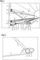
- FIG. 1 shows an embodiment of the luggage rack 1 according to the invention, which has a storage part 2, a clamping device 3 and a support profile 4.
- the storage part 2 forms on its mounting side a mounting flange 5, by which the storage part 2 is fixed to a car body 6 of a rail vehicle by screws 7. At its front side facing away from the attachment side 5, the storage part forms a hollow profile 8.
- FIG. 2 shows the embodiment of the hollow section 8 in more detail. It can be seen that the hollow profile 8 is elliptical. In a cavity 9 of the hollow section 8 part-cylindrical abutment surfaces are designed as a receiving warehouse 10, whose function will be discussed in more detail later. Out FIG. 1 is also apparent that extends between the hollow section 8 and the mounting flange 5, a flat perforated support portion 11.
- the clamping device 3 is used for clamping the front of the storage part 2 on the car body 6.
- the clamping device 3 comprises a circular cylindrical bearing pin 12 which is rotatably arranged in the receiving bearing 10 of the hollow section 8 is.
- the bearing pin 12 is rotatably and positively against the abutment surfaces, so the receiving warehouse 10, to.
- In the hollow section 8 is facing away from the front edge and in the FIG. 1 Therefore, invisible rear side formed a slot, so that a connecting rod 13 with the exciting, so the bearing pin 12, can be firmly connected, wherein the rotation of the journal 12 is maintained in the receiving warehouse 10.
- the connecting rod 13 is part of a connecting unit 14 which, in addition to the connecting rod 13, comprises a carrier element 15 into which the connecting rod partially projects.
- the carrier element 15 has a self-locking internal thread, with which the connecting rod 13 can be firmly clamped in the carrier element 15.
- the connection unit 14 is therefore telescopically extendible in length.
- the carrier element 15 is connected via a pivotable connection, which will be discussed in more detail later, with a car body holder 16 which is fixedly mounted on the car body 6 via a screw connection.
- the clamping device 3 is thus to a length variable and can span with the support portion of the storage part with respect to the journal any angle. In this way, the luggage rack 1 can be mounted variable to any car bodies.
- the support profile 4 also has a mounting flange 5, on which the support profile 4 is bolted to the car body 6.
- the support profile 4 is provided on its side applied by the mounting flange 5 side with a mounting groove 17, in which a fastening lug 18 of the storage part 2 engages. In this way, a tongue and groove profiling is formed, which is provided for the positive connection of the support profile with the storage part.
- an opening-free flat Abdeckwandung 33 extends so that from this the support portion 11 and the car body 6, a opaque cable channel 26 is limited.
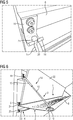
- FIGS. 3 and 4 is the luggage rack according to FIG. 1 mounted in different car bodies. It can be seen that the car body 6 according to FIG. 3 a different cross-sectional geometry aufeist than the car body according to FIG. 4 , In order to be able to be variably attached to the different attachment levels, the angle of the clamping device 3 and the length of the connecting element 14 are variably selectable, so that the luggage rack 1 according to the invention can be conveniently used in both car body profiles.
- FIG. 5 shows the attachment end of the clamping device 3 in more detail. It can be seen that a carbody holder 16 is formed at the attachment end. The car body holder 16 is firmly bolted to the car body 6 on the one hand. Further, a gripping portion 19 is formed, in which a receiving slot 20 is formed. In the receiving slot 20, the carrier element 15 engages with its carriage-side end, on which the carrier element 15 forms a spherical cap 21. Due to the spherical cap 21 and the related complementary complementary receiving slot 20, the support member 15 can be pivoted relative to the car body holder 16. Due to the shape complementary design of the ball cap 21 and receiving slot 20 is at all angular settings of the clamping device 3 is always a precise investment of the ball cap 21 on the gripping portion 19 and thus ensures a uniform adhesion between these components.
- FIG. 6 shows a further embodiment of the luggage rack according to the invention 1. This corresponds largely to the luggage rack 1 according to FIG. 1 , however, inner lining elements 22 and 23 are provided, wherein the inner lining element 22 is supported in an integrally formed groove 24 of the storage part 2.
- the attachment of the interior trim element 22 on the car body is in FIG. 6 figuratively not shown. However, this is done conveniently by a simple screw.
- the support profile 4 has a cover groove 25 in which the cover 23 can be snapped for sole attachment.
- FIG. 7 shows the luggage rack according to FIG. 1 in a different perspective view, in which on the one hand, the tongue and groove profiling 17, 18 between the storage part 2 and 4 support profile is more clearly visible. Furthermore, it is shown that between the support profile 4 and storage part 2, a circumferentially closed cable channel 26 is formed. In the cable channel 26 thus cables can be invisibly and comfortably guided from the outside.
- FIG. 8 shows the embodiment according to FIG. 6 , wherein end caps 27 and 28 can be seen, with which the frontal openings of the hollow section 8 and the cable channel 26 can be hidden for aesthetic reasons.
- the luggage rack according to the invention has a plurality of storage parts and support profiles 4 lying one behind the other.
- storage part 2 and support profile 4 are formed as a so-called continuous carrier, so that they can be brought to a suitable length, for example, by sawing off end pieces. In this way, any length adjustments of the luggage rack can be made.
- the storage parts can be shortened.
- Each storage part is braced here with two clamping devices 3, which are each rotatably arranged on one of the two end faces of the storage part 2 in the hollow section 8 and the receiving bearing 10 of the hollow section 8.
- FIG. 9 shows the luggage rack 1 from below.
- the support profile 4 also serves for the attachment of additional modules 29.
- the additional modules 29 each have two reading lamps 30 and a screen 31 for displaying information.
- the power supply of this additional module via the concealed profile carrier 4 cable channel, in which a power supply cable is arranged.
- the attachment of the additional modules 29 is carried out by inserting a figuratively not shown fastening lug of the additional module 29 behind a in FIG. 7 illustrated mounting rail 32, which is formed on the support profile.
- At the car side At the end of each additional module 29 is connected in the embodiment shown by a simple screw with the support section 4.
Landscapes
- Engineering & Computer Science (AREA)
- Mechanical Engineering (AREA)
- Fittings On The Vehicle Exterior For Carrying Loads, And Devices For Holding Or Mounting Articles (AREA)
- Vehicle Step Arrangements And Article Storage (AREA)
Abstract
Description
- Die Erfindung betrifft eine Gepäckablage für Schienenfahrzeuge.
- Aus der Praxis sind Gepäckablagen bekannt, die an die Ausgestaltung des Wagenkastens eines Schienenfahrzeugs, in dem die jeweilige Gepäckablage montiert ist, individuell angepasst sind. Dabei weisen die Gepäckablagen in der Regel eine sich in einer Längsrichtung erstreckende Ablage auf, die über Haltebügel an der Seitenwand oder aber der Deckenwand befestigt wird. Jeder Haltebügel ist daher in der Regel unter Berücksichtigung der Geometrie des Wagenkastens entworfen worden. Bei im Wesentlichen rechteckigen Wagenkästen weist der Haltebügel entsprechende Befestigungskanten auf und sorgt so für einen Halt der horizontalen Ablage an dem Wagenkasten. Insbesondere bei Hochgeschwindigkeitszügen sind die Wagenkästen jedoch beim Übergang von der Seitenwand und den Deckenbereich bogenförmig ausgebildet, so dass der Luftwiderstand des Schienenfahrzeugs verringert ist. Diese bogenförmige Geometrie muss bei bisherigen Gepäckablagen bereits bei deren Entwurf berücksichtigt werden. Aus diesem Grunde bleibt die Verwendung einer Gepäckablage auf eine bei der Entwicklung der Ablage vorgegebene Wagenkastengeometrie beschränkt. Eine einfache Übertragbarkeit auf einen anderen Fahrzeugquerschnitt mit horizontal und vertikal zur ursprünglichen Lage versetzten Befestigungsebenen ist nicht möglich. In solchen Fällen ist daher in der Regel eine neue Konstruktion der Gepäckablage oder zumindest eine Anpasskonstruktion erforderlich. Dies wird auch sogar noch erschwert, wenn Gepäckablagen Zusatzmodule, wie beispielsweise Leseleuchten, Bildschirme, Lautsprecher und Kabelführungskanäle aufweisen.
- Aufgabe der Erfindung ist es daher, eine Gepäckablage bereitzustellen, die auf einfache Art und Weise an unterschiedliche Wagenkastengeometrien anpassbar ist.
- Die Erfindung löst diese Aufgabe durch eine Gepäckablage für ein Schienenfahrzeug mit in Längsrichtung hintereinander angeordneten Ablageteilen zur Aufnahme von Gepäckstücken, wobei jedes Ablageteil an einer Befestigungsseite mit dem Schienenfahrzeug verbindbar ist und an einer von der Befestigungsseite abgewandten Vorderseite wenigstens ein Aufnahmelager ausbildet, und Spanneinrichtungen, die mit einem Spannende drehbar in dem oder in einem der Aufnahmelager angeordnet und an einem von dem Spannende abgewandten Befestigungsende an dem Schienenfahrzeug befestigbar sind.
- Die erfindungsgemäße Gepäckablage ist aus Ablageteilen zusammengesetzt, die nach erfolgter Montage in einem Wagenkasten des Schienenfahrzeugs sich auf einer gemeinsamen Ablagehöhe hintereinander erstrecken. Dabei stoßen die Ablageteile stirnseitig aneinander an. Jedes Ablageteil weist eine Befestigungsseite mit Befestigungsmitteln auf, die eine Montage des Ablageteils an der Innenseite des Wagenkastens ermöglichen. An seiner der Befestigungsseite gegenüber liegenden Vorderseite ist jedes Ablageteil an dem Wagenkasten verspannt. Zum Verspannen der Vorderseite bildet das Ablageteil ein Aufnahmelager aus, in dem ein Ende einer Spanneinrichtung drehbar gelagert ist. Durch diese drehbare Lagerung kann der zwischen der Spanneinrichtung und dem Ablageteil bezüglich des Aufnahmelagers ausgebildete Winkel variiert werden. Durch diese drehbare Lagerung ist es daher möglich, die Spanneinrichtung an unterschiedliche Wagenkastengeometrien anzupassen. Lediglich die Länge der Spanneinrichtung muss noch individuell entsprechend der jeweils vorgesehenen Wagenkastengeometrie angepasst werden.
- Erfindungsgemäß ist somit eine Gepäckablage bereitgestellt, die schnell, einfach und somit kostengünstig bei verschiedenen Fahrzeugtypen mit unterschiedlicher Wagenkastengeometrie eingesetzt werden kann.
- Gemäß einer zweckmäßigen Weiterentwicklung weist die Spanneinrichtung eine sich zwischen dem Spannende und dem Befestigungsende erstreckende Verbindungseinheit auf, die teleskopartig verlängerbar ist. Gemäß dieser bevorzugten Weiterentwicklung der Erfindung ist es noch nicht einmal mehr nötig, die Spanneinrichtung hinsichtlich ihrer Länge auf die Wagenkastengeometrie anzupassen. Vielmehr kann die so weiterentwickelte erfindungsgemäße Gepäckablage vollständig unabhängig von einem Wagenkasten hergestellt und anschließend in beliebigen Wagenkästen montiert werden. Dies ermöglicht die winkelvariable Verbindung zwischen Spanneinrichtung und Ablageteil einerseits und die gleichzeitige variable Länge der Spanneinheit.
- Zweckmäßigerweise weist das Spannende einen Lagerzapfen auf, wobei das Aufnahmelager zumindest abschnittsweise formkomplementär zum Lagerzapfen ausgebildet ist, so dass eine formschlüssige drehbare Verbindung bereitgestellt ist. Der Lagerzapfen ist gemäß dieser Ausgestaltung vom Rest der Spanneinrichtung lösbar und kann nach dem Einschieben in das Aufnahmelager mit der restlichen Spanneinrichtung verbunden werden.
- Gemäß einer diesbezüglich zweckmäßigen Weiterentwicklung ist an der Vorderseite des Ablageteils ein Hohlprofil ausgebildet, das ein zum Lagerzapfen formkomplementäres Gegenlager über die gesamte Länge des Ablageteils hinweg ausbildet. Gemäß dieser vorteilhaften Weiterentwicklung kann jedes Ablageteil beispielsweise durch Sägen oder dergleichen einfach verkürzt und so an die individuellen Erfordernisse hinsichtlich der Längserstreckung des Schienenfahrzeugs angepasst werden.
- Zweckmäßigerweise weist das Befestigungsende eine Wagenkastenhalterung auf, mit der die Verbindungseinheit schwenkbar verbunden ist. Mit dieser zweckmäßigen Weiterentwicklung wird zum einen die Montage des Befestigungsendes an den Wagenkasten erleichtert, wobei gleichzeitig für eine möglichst gleichmäßige Einleitung der Zugkraft von der Wagenkastenhalterung in die Verbindungseinheit gesorgt ist. Die schwenkbare Verbindung kann beispielsweise durch eine Kugelkappe realisiert werden, die in einen Aufnahmeschlitz eines Greifabschnittes der Wagenhalterung eingreift und so für eine formschlüssige Verbindung zwischen Verbindungseinheit und Wagenkastenhalterung sorgt, die auf Zug beanspruchbar ist und dabei verschwenkt werden kann. Darüber hinaus sind jedoch im Rahmen der Erfindung jedoch auch abweichende schwenkbare Verbindungen, wie beispielsweise Scharniere oder dergleichen, einsetzbar.
- Gemäß einer bevorzugten Ausgestaltung ist das Ablageteil im Bereich seiner Befestigungsseite mit einem Stützprofil verbunden, wobei sich das Stützprofil ebenfalls mit dem Wagenkasten verbindbar ist. Das Stützprofil erstreckt sich im befestigten Zustand unterhalb des Ablageteils und sorgt für einen verbesserten Halt des Ablageteils am Wagenkasten.
- Zweckmäßigerweise sind sowohl Ablageteil als auch Stützprofil als Durchlaufträger ausgebildet. Mit anderen Worten weist jedes Ablageteil über seine Längserstreckung die gleiche Geometrie auf. Dies gilt entsprechend für das Stützprofil. Ablageteil und Stützprofil können somit verkürzt und die verkürzten Ablageteile und Stützprofile wieder hintereinander angeordnet werden, so dass auf diese Weise eine zweckmäßige Längsanpassung der erfindungsgemäßen Gepäckablage ermöglicht ist.
- Vorteilhafterweise ist jedes Ablageteil mit einem zugeordneten Stützprofil über eine Nutfederprofilierung miteinander verbunden. Die Nut-Feder-Profilierung ermöglicht eine gleichmäßige formschlüssige Verbindung über die gesamte Längserstreckung von Stützprofil und Ablage.
- Abweichend hiervon kann jedes Ablageteil mit dem zugeordneten Stützprofil auch auf andere Art und Weise verklemmt sein. Wesentlich ist, dass Stützprofil und Ablageteil über eine formschlüssige Verbindung miteinander befestigbar sind. Dies erleichtert die Montage von der erfindungsgemäßen Gepäckablage. Gemäß einer bevorzugten Ausgestaltung bildet jedes Stützprofil mit dem zugeordneten Ablageteil einen umfänglich geschlossenen Kabelkanal zur Aufnahme von elektrischen Kabeln aus. Hierzu bildet das Stützprofil beispielsweise eine flächige Begrenzungswandung aus, die sich zwischen ihrer Befestigungsseite, mit der sie am Schienenfahrzeug befestigt ist, und ihrer Verbindungsseite erstreckt, an der sie mit dem Ablageteil verbunden ist. Die erfindungsgemäße Gepäckablage kann daher neben der reinen Funktion als Unterbringungsort für Gepäckstücke auch Kabelführungsfunktionen übernehmen. Der Kabelkanal ist auch vorteilhaft im Hinblick auf die Energieversorgung von Zusatzmodulen, die mit einer Leselampe, Bildschirmanzeige oder dergleichen ausgerüstet sind. Hierauf wird im Folgenden noch genauer eingegangen werden.
- Vorteilhafterweise weist jedes Ablageteil und/oder jedes Stützprofil wenigstens ein Innenverkleidungselement auf. Die Innenverkleidungselemente ermöglichen eine Verschönerung der erfindungsgemäßen Gepäckablage, da Befestigungsteile, wie Nieten, Verschraubungen am Wagenkasten oder dergleichen, verdeckt werden können. Zur Befestigung des jeweiligen Innenverkleidungselements weist jedes Ablageteil und/oder jedes Stützprofil eine Nut auf. In diese Nut ist das Innenverkleidungselement beispielsweise mit seiner Unterkante einstellbar, so dass sein Eigengewicht durch diese Nut im Wesentlichen aufgenommen ist und an seiner von der besagten Nut abweichenden Seite lediglich leicht an dem Wagenkasten fixiert werden muss.
- Zweckmäßigerweise bildet jedes Stützprofil Befestigungsmittel aus, an denen Zusatzmodule formschlüssig befestigbar sind. Solche Befestigungselemente sind beispielsweise Befestigungsnuten, Klemmschienen oder dergleichen, in denen das Zusatzmodul eingehakt oder verklemmt werden kann. Hierzu weist das Zusatzmodul beispielsweise eine Befestigungsnase auf. Darüber hinaus kann das Zusatzmodul mit einer weiteren Verbindung, beispielsweise Schraubverbindung, mit dem Stützprofil verbunden werden. Zusatzmodule sind beispielsweise Einrichtungen, in denen Lautsprecher, Beleuchtungseinrichtungen, Displays, Netzzugangsstecker oder dergleichen, integriert sind. Insbesondere bei Ausbildung eines Kabelkanals kann ein solches Zusatzmodul auf einfache Art und Weise mit Energie versorgt werden. Auch die kabelgeführte Verbindung eines Rechners am Platz mit einem zentralen Rechner oder sonstigen Gerätes des Schienenfahrzeugs ist auf diese Weise möglich.
- Gemäß einer bevorzugten Ausgestaltung weist das Ablageteil einen flächigen Tragabschnitt auf, der gelocht ist. Das Gepäckstück wird auf dem Tragabschnitt abgelegt, so dass eine gelochte Ausgestaltung die Beobachtung des Gepäckstückes von einem unteren Sitz aus ermöglicht. Darüber hinaus macht die gelochte Ausgestaltung des Tragabschnittes das Ablageteil leichter, wodurch das Eigengewicht der gesamten erfindungsgemäßen Gepäckablage herabgesetzt ist. Durch die Lochung kann auch Designanforderungen begegnet werden.
- Weitere zweckmäßige Ausgestaltungen und Vorteile der Erfindung sind Gegenstand der nachfolgenden Beschreibung von Ausführungsbeispielen der Erfindung unter Bezug auf die Figuren der Zeichnung, wobei gleiche Bezugszeichen auf gleich wirkende Bauteile verweisen und wobei
- Figur 1
- ein Ausführungsbeispiel der erfindungsgemäßen Gepäckablage in einer perspektivischen Ansicht,
- Figur 2
- eine vergrößerte Darstellung des vorderen Teils der Gepäckablage gemäß
Figur 1 in einer Seitenansicht, - Figuren 3 und 4
- ein Ausführungsbeispiel der erfindungsgemäßen Gepäckablage in einer Seitenansicht montiert in unterschiedlichen Wagenkästen,
- Figur 5
- das Befestigungsende einer Spanneinrichtung der Gepäckablage gemäß
Figur 1 , - Figur 6
- ein weiteres Ausführungsbeispiel der erfindungsgemäßen Gepäckablage,
- Figur 7
- eine vergrößerte Darstellung eines Teils der erfindungsgemäßen Gepäckablage gemäß
Figur 1 , - Figur 8
- ein weiteres Ausführungsbeispiel der erfindungsgemäßen Gepäckablage und
- Figur 9
- ein weiteres Ausführungsbeispiel der erfindungsgemäßen Gepäckablage zeigen.
-
Figur 1 zeigt ein Ausführungsbeispiel der erfindungsgemäßen Gepäckablage 1, die ein Ablageteil 2, eine Spanneinrichtung 3 sowie ein Stützprofil 4 aufweist. - Das Ablageteil 2 bildet an seiner Befestigungsseite einen Befestigungsflansch 5 aus, durch den das Ablageteil 2 an einem Wagenkasten 6 eines Schienenfahrzeugs durch Schrauben 7 befestigt ist. An seiner von der Befestigungsseite 5 abgewandten Vorderseite bildet das Ablageteil ein Hohlprofil 8 aus.
-
Figur 2 zeigt die Ausgestaltung des Hohlprofils 8 genauer. Es ist erkennbar, dass das Hohlprofil 8 elliptisch ist. In einem Hohlraum 9 des Hohlprofils 8 sind teilzylindrische Gegenlagerflächen als Aufnahmelager 10 ausgebildet, auf deren Funktion später noch genauer eingegangen werden wird. AusFigur 1 ist ferner erkennbar, dass sich zwischen dem Hohlprofil 8 und dem Befestigungsflansch 5 ein flächiger gelochter Tragabschnitt 11 erstreckt. - Die Spanneinrichtung 3 dient zum Festspannen der Vorderseite des Ablageteils 2 an dem Wagenkasten 6. Dazu umfasst die Spanneinrichtung 3 einen kreiszylindrischen Lagerzapfen 12, der drehbar in dem Aufnahmelager 10 des Hohlprofils 8 angeordnet ist. Dabei liegt der Lagerzapfen 12 drehbar und formschlüssig an den Gegenlagerflächen, also dem Aufnahmelager 10, an. In das Hohlprofil 8 ist an seiner von der Vorderkante abgewandten und in der
Figur 1 daher nicht sichtbaren Hinterseite ein Langloch ausgebildet, so dass eine Verbindungsstange 13 mit dem Spannende, also dem Lagerzapfen 12, fest verbunden werden kann, wobei die Drehbarkeit des Lagerzapfens 12 in dem Aufnahmelager 10 erhalten bleibt. Die Verbindungsstange 13 ist Teil einer Verbindungseinheit 14, die neben der Verbindungsstange 13 ein Trägerelement 15 umfasst, in das die Verbindungsstange teilweise hineinragt. Dabei weist das Trägerelement 15 ein selbsthemmendes Innengewinde auf, mit dem die Verbindungsstange 13 fest in dem Trägerelement 15 verklemmt werden kann. Die Verbindungseinheit 14 ist daher in ihrer Länge teleskopartig verlängerbar. Das Trägerelement 15 ist über eine schwenkbare Verbindung, auf die später noch genauer eingegangen werden wird, mit einem Wagenkastenhalter 16 verbunden, der über eine Schraubverbindung fest an dem Wagenkasten 6 montiert. Die Spanneinrichtung 3 ist somit zu einen längenveränderbar und kann mit dem Tragabschnitt des Ablageteils bezüglich des Lagerzapfens beliebige Winkel aufspannen. Auf diese Weise kann die Gepäckablage 1 an beliebige Wagenkästen variable montiert werden. - Das Stützprofil 4 weist ebenfalls einen Befestigungsflansch 5 auf, an dem das Stützprofil 4 fest mit dem Wagenkasten 6 verschraubt ist. Das Stützprofil 4 ist an seiner vom Befestigungsflansch 5 angewandten Seite mit einer Befestigungsnut 17 ausgestattet, in welche eine Befestigungsnase 18 des Ablageteils 2 eingreift. Auf diese Art und Weise ist eine Nut-Feder-Profilierung ausgebildet, die zur formschlüssigen Verbindung des Stützprofils mit dem Ablageteil bereitgestellt ist. Zwischen der Befestigungsnut 17 und dem Befestigungsflansch 5 erstreckt sich eine öffnungsfreie flächige Abdeckwandung 33, so dass von dieser dem Tragabschnitt 11 und dem Wagenkasten 6 ein blickdichter Kabelkanal 26 begrenzt ist.
- In den
Figuren 3 und 4 ist die Gepäckablage gemäßFigur 1 in unterschiedlichen Wagenkästen montiert. Es ist erkennbar, dass der Wagenkasten 6 gemäßFigur 3 eine andere Querschnittsgeometrie aufeist, als der Wagenkasten gemäßFigur 4 . Um an die unterschiedlichen Befestigungsebenen variabel angebracht werden zu können, sind die Winkel der Spanneinrichtung 3 und die Länge des Verbindungselementes 14 variabel wählbar, so dass die erfindungsgemäße Gepäckablage 1 bequem in beide Wagenkastenprofilen eingesetzt werden kann. -
Figur 5 zeigt das Befestigungsende der Spanneinrichtung 3 genauer. Es ist erkennbar, dass an dem Befestigungsende ein Wagenkastenhalter 16 ausgebildet ist. Der Wagenkastenhalter 16 ist zum einen an dem Wagenkasten 6 fest verschraubt. Ferner ist ein Greifabschnitt 19 ausgebildet, in dem ein Aufnahmeschlitz 20 ausgebildet ist. In dem Aufnahmeschlitz 20 greift das Trägerelement 15 mit seinem wagenkastenseitigen Ende ein, an dem das Trägerelement 15 eine Kugelkappe 21 ausbildet. Aufgrund der Kugelkappe 21 und dem diesbezügliche formkomplementären Aufnahmeschlitz 20 kann das Trägerelement 15 bezüglich des Wagenkastenhalters 16 verschwenkt werden. Durch die formkomplementäre Ausgestaltung von Kugelkappe 21 und Aufnahmeschlitz 20 ist bei allen Winkeleinstellungen der Spanneinrichtung 3 stets eine exakte Anlage der Kugelkappe 21 an dem Greifabschnitt 19 und somit eine gleichmäßiger Kraftschluss zwischen diesen Bauteilen sichergestellt. -
Figur 6 zeigt ein weiteres Ausführungsbeispiel der erfindungsgemäßen Gepäckablage 1. Diese entspricht weitestgehend der Gepäckablage 1 gemäßFigur 1 . Jedoch sind Innenverkleidungselemente 22 und 23 vorgesehen, wobei das Innenverkleidungselement 22 in einer angeformten Nut 24 des Ablageteils 2 abgestützt ist. Die Befestigung des Innenverkleidungselements 22 am Wagenkasten ist inFigur 6 figürlich nicht dargestellt. Dies erfolgt jedoch hier praktischerweise durch eine einfache Schraubverbindung. Auch das Stützprofil 4 weist eine Abdeckungsnut 25 auf, in dem die Abdeckung 23 zur alleinigen Befestigung eingerastet werden kann. -
Figur 7 zeigt die Gepäckablage gemäßFigur 1 in einer abweichenden perspektivischen Ansicht, in welcher zum einen die Nut-Feder-Profilierung 17, 18 zwischen Ablageteil 2 und Stützprofil 4 genauer erkennbar ist. Ferner ist gezeigt, dass zwischen Stützprofil 4 und Ablageteil 2 ein umfänglich geschlossener Kabelkanal 26 ausgebildet ist. In dem Kabelkanal 26 können somit Kabel von außen unsichtbar und bequem geführt werden. -
Figur 8 zeigt das Ausführungsbeispiel gemäßFigur 6 , wobei Endkappen 27 und 28 erkennbar sind, mit denen die stirnseitigen Öffnungen des Hohlprofils 8 sowie des Kabelkanals 26 aus ästhetischen Gründen verdeckt werden können. Ferner ist erkennbar, dass die erfindungsgemäße Gepäckablage mehrere hintereinander liegende Ablageteile und Stützprofile 4 aufweist. Dabei sind Ablageteil 2 und Stützprofil 4 als so genannte Durchlaufträger ausgebildet, so dass diese beispielsweise durch Absägen von Endstücken auf eine passende Länge gebracht werden können. Auf diese Art und Weise können beliebige Längenanpassungen der Gepäckablage vorgenommen werden. Um die Anzahl der Spannelemente zu erhöhen, können die Ablageteile verkürzt werden. Jedes Ablageteil wird hier mit jeweils zwei Spanneinrichtungen 3 verspannt, die jeweils an einer der beiden Stirnseiten des Ablageteils 2 in dem Hohlprofil 8 beziehungsweise dem Aufnahmelager 10 des Hohlprofils 8 drehbar angeordnet sind. -
Figur 9 zeigt die Gepäckablage 1 von unten. Hier ist erkennbar, dass das Stützprofil 4 auch zur Befestigung von Zusatzmodulen 29 dient. Die Zusatzmodule 29 weisen jeweils zwei Leselampen 30 sowie einen Bildschirm 31 zur Informationsanzeige auf. Die Stromversorgung dieses Zusatzmoduls erfolgt über den vom Profilträger 4 verdeckten Kabelkanal, in dem auch ein Energieversorgungskabel angeordnet ist. Die Befestigung der Zusatzmodule 29 erfolgt durch Einsetzen einer figürlich nicht dargestellten Befestigungsnase des Zusatzmoduls 29 hinter eine inFigur 7 genauer dargestellte Befestigungsschiene 32, die an dem Stützprofil ausgebildet ist. An dem wagenseitigen Ende ist jedes Zusatzmodul 29 in dem gezeigten Ausführungsbeispiel durch eine einfache Schraube mit dem Stützprofil 4 verbunden.
Claims (13)
- Gepäckablage (1) für ein Schienenfahrzeug (6) mit in Längsrichtung hintereinander angeordneten Ablageteilen (2) zur Aufnahme von Gepäckstücken, wobei jedes Ablageteil (2) an einer Befestigungsseite (5) mit dem Schienenfahrzeug (6) verbindbar ist und an einer von der Befestigungsseite (5) abgewandten Vorderseite (8) wenigstens ein Aufnahmelager (10) ausbildet, und Spanneinrichtungen (3), die mit einem Spannende (12) drehbar in dem oder in einem der Aufnahmelager (10) angeordnet und an einem von dem Spannende (12) abgewandten Befestigungsende (16) an dem Schienenfahrzeug (6) befestigbar sind.
- Gepäckablage (1) nach Anspruch 1,
dadurch gekennzeichnet, dass die Spanneinrichtung (3) eine sich zwischen dem Spannende (12) und dem Befestigungsende (16) erstreckende Verbindungseinheit (14) aufweist, die teleskopartig verlängerbar ist. - Gepäckablage (1) nach Anspruch 2,
dadurch gekennzeichnet, dass das Spannende als Lagerzapfen (12) ausgebildet ist, wobei das Aufnahmelager (10) zumindest abschnittsweise formkomplementär zum Lagerzapfen (12) ausgebildet ist, so dass eine formschlüssige drehbare Verbindung bereitgestellt ist. - Gepäckablage (1) nach Anspruch 3,
dadurch gekennzeichnet, dass an der Vorderseite des Ablageteils ein Hohlprofil (8) ausgebildet ist, das ein zum Lagerzapfen (12) formkomplementäres Gegenlager (10) über die gesamte Länge des Ablageteils (2) hinweg ausbildet. - Gepäckablage (1) nach einem der Ansprüche 2 bis 4, dadurch gekennzeichnet, dass das Befestigungsende eine Wagenkastenhalterung (16) aufweist, mit der die Verbindungseinheit (14) schwenkbar verbunden ist.
- Gepäckablage (1) nach einem der vorhergehenden Ansprüche, dadurch gekennzeichnet, dass das Ablageteil (2) im Bereich seiner Befestigungsseite (5) mit einem Stützprofil (4) verbunden ist, wobei das Stützprofil (4) mit dem Schienenfahrzeug (6) verbindbar ist.
- Gepäckablage (1) nach Anspruch 6,
dadurch gekennzeichnet, dass jedes Ablageteil (2) und jedes Stützprofil (4) als Durchlaufträger ausgebildet sind. - Gepäckablage (1) nach Anspruch 7,
dadurch gekennzeichnet, dass jedes Ablageteil (2) mit einem zugeordneten Stützprofil (4) über eine Nutfederprofilierung (17,18) verbunden ist. - Gepäckablage (1) nach einem der Ansprüche 6 bis 8,
dadurch gekennzeichnet, dass jedes Stützprofil (4) mit dem zugeordneten Ablageteil (2) einen umfänglich geschlossenen Kabelkanal (26) zur Aufnahme von elektrischen Kabeln ausbildet. - Gepäckablage (1) nach einem der Ansprüche 6 bis 9,
dadurch gekennzeichnet, dass jedes Ablageteil (2) und/oder jedes Stützprofil (4) wenigstens ein Innenverkleidungselement (22,13) aufweist(en). - Gepäckablage (1) nach Anspruch 10,
dadurch gekennzeichnet, dass jedes Ablageteil (2) und/oder jedes Stützprofil (4) eine Nut (24,25) zur Aufnahme des jeweiligen Innenverkleidungselements (22,23) ausbildet (en) . - Gepäckablage (1) nach einem der Ansprüche 6 bis 11,
dadurch gekennzeichnet, dass jedes Stützprofil (4) ein Befestigungselement (32) ausbildet, an dem Zusatzmodule (29) formschlüssig befestigbar sind. - Gepäckablage (1) nach einem der vorhergehenden Ansprüche,
dadurch gekennzeichnet, dass jedes Ablageteil (2) einen flächigen Tragabschnitt (11) aufweist, der gelocht ist.
Applications Claiming Priority (1)
| Application Number | Priority Date | Filing Date | Title |
|---|---|---|---|
| DE201110004894 DE102011004894A1 (de) | 2011-03-01 | 2011-03-01 | Modulare Gepäckablage |
Publications (3)
| Publication Number | Publication Date |
|---|---|
| EP2495150A2 true EP2495150A2 (de) | 2012-09-05 |
| EP2495150A3 EP2495150A3 (de) | 2013-04-17 |
| EP2495150B1 EP2495150B1 (de) | 2014-09-17 |
Family
ID=45656384
Family Applications (1)
| Application Number | Title | Priority Date | Filing Date |
|---|---|---|---|
| EP20120156470 Not-in-force EP2495150B1 (de) | 2011-03-01 | 2012-02-22 | Modulare Gepäckablage |
Country Status (3)
| Country | Link |
|---|---|
| EP (1) | EP2495150B1 (de) |
| DE (1) | DE102011004894A1 (de) |
| ES (1) | ES2524902T3 (de) |
Cited By (8)
| Publication number | Priority date | Publication date | Assignee | Title |
|---|---|---|---|---|
| DE102012221974A1 (de) * | 2012-11-30 | 2014-06-05 | Siemens Aktiengesellschaft | Fahrzeug mit Löscheinrichtung |
| CN104773183A (zh) * | 2015-04-13 | 2015-07-15 | 南京工业职业技术学院 | 一种行李取放装置 |
| WO2015144416A1 (de) * | 2014-03-28 | 2015-10-01 | Siemens Aktiengesellschaft | Fahrzeug, insbesondere schienenfahrzeug mit passagierbereich und gepäckbereich |
| CN104986170A (zh) * | 2015-06-15 | 2015-10-21 | 南京工业职业技术学院 | 自动火车行李取放装置 |
| CN106360934A (zh) * | 2016-08-26 | 2017-02-01 | 重庆交通大学 | 用于固定行李箱的装置 |
| WO2017125217A1 (de) * | 2016-01-21 | 2017-07-27 | Siemens Aktiengesellschaft | Gepäckablagemodul für ein fahrzeug |
| EP3392559A4 (de) * | 2015-12-15 | 2018-10-24 | CRRC Qingdao Sifang Co., Ltd. | Schienenfahrzeugleuchte |
| CN116691756A (zh) * | 2023-07-21 | 2023-09-05 | 江阴奇南机械有限公司 | 一种防掉落行李架及轨道车 |
Families Citing this family (1)
| Publication number | Priority date | Publication date | Assignee | Title |
|---|---|---|---|---|
| DE102016202077A1 (de) * | 2016-02-11 | 2017-08-17 | Siemens Aktiengesellschaft | Gepäckablagenmodul zum Aufbau einer Gepäckablage in einem Schienenfahrzeug |
Family Cites Families (9)
| Publication number | Priority date | Publication date | Assignee | Title |
|---|---|---|---|---|
| FR361605A (fr) * | 1905-07-03 | 1906-09-13 | Bricard Freres Soc | Porte-bagages pour wagons |
| US927235A (en) * | 1909-02-24 | 1909-07-06 | William S Hamm | Baggage-rack. |
| DE1025441B (de) * | 1954-10-25 | 1958-03-06 | Erich Mory | Gepaeckablage, insbesondere in Fahrzeugen fuer den Personenverkehr |
| FR1491361A (fr) * | 1966-06-11 | 1967-08-11 | Porte-bagages pour voiture de chemin de fer | |
| US5441326A (en) * | 1993-01-22 | 1995-08-15 | Transmatic, Inc. | Combined air conditioning duct, luggage compartment and lighting fixture for mass transit vehicles |
| DE19614659A1 (de) * | 1996-04-13 | 1997-10-16 | Hymer Leichtmetallbau | Neigungsverstellbare Halterung für eine Gepäckablage |
| DE29700267U1 (de) * | 1997-01-09 | 1997-02-27 | Reiche Gmbh & Co Kg Ausstattun | Aus einer Mehrzahl nebeneinanderliegender Ablageplatten bestehende Gepäckablage für Fahrzeuge |
| DE202007003708U1 (de) * | 2007-03-13 | 2007-07-05 | Biniaminov, Youri | Gepäckablage |
| DE102007052493A1 (de) * | 2007-11-02 | 2009-05-14 | Siemens Ag | Gepäckablage für Schienenfahrzeuge |
-
2011
- 2011-03-01 DE DE201110004894 patent/DE102011004894A1/de not_active Withdrawn
-
2012
- 2012-02-22 ES ES12156470.2T patent/ES2524902T3/es active Active
- 2012-02-22 EP EP20120156470 patent/EP2495150B1/de not_active Not-in-force
Non-Patent Citations (1)
| Title |
|---|
| None |
Cited By (13)
| Publication number | Priority date | Publication date | Assignee | Title |
|---|---|---|---|---|
| DE102012221974A1 (de) * | 2012-11-30 | 2014-06-05 | Siemens Aktiengesellschaft | Fahrzeug mit Löscheinrichtung |
| WO2015144416A1 (de) * | 2014-03-28 | 2015-10-01 | Siemens Aktiengesellschaft | Fahrzeug, insbesondere schienenfahrzeug mit passagierbereich und gepäckbereich |
| CN104773183B (zh) * | 2015-04-13 | 2017-03-22 | 南京工业职业技术学院 | 一种行李取放装置 |
| CN104773183A (zh) * | 2015-04-13 | 2015-07-15 | 南京工业职业技术学院 | 一种行李取放装置 |
| CN104986170B (zh) * | 2015-06-15 | 2017-05-24 | 南京工业职业技术学院 | 自动火车行李取放装置 |
| CN104986170A (zh) * | 2015-06-15 | 2015-10-21 | 南京工业职业技术学院 | 自动火车行李取放装置 |
| EP3392559A4 (de) * | 2015-12-15 | 2018-10-24 | CRRC Qingdao Sifang Co., Ltd. | Schienenfahrzeugleuchte |
| US10822001B2 (en) | 2015-12-15 | 2020-11-03 | Crrc Qingdao Sifang Co., Ltd. | Rail vehicle lighting device |
| WO2017125217A1 (de) * | 2016-01-21 | 2017-07-27 | Siemens Aktiengesellschaft | Gepäckablagemodul für ein fahrzeug |
| RU186749U1 (ru) * | 2016-01-21 | 2019-01-31 | Сименс Акциенгезелльшафт | Модуль багажной полки для транспортного средства |
| CN106360934A (zh) * | 2016-08-26 | 2017-02-01 | 重庆交通大学 | 用于固定行李箱的装置 |
| CN106360934B (zh) * | 2016-08-26 | 2018-01-09 | 重庆交通大学 | 用于固定行李箱的装置 |
| CN116691756A (zh) * | 2023-07-21 | 2023-09-05 | 江阴奇南机械有限公司 | 一种防掉落行李架及轨道车 |
Also Published As
| Publication number | Publication date |
|---|---|
| ES2524902T3 (es) | 2014-12-15 |
| EP2495150B1 (de) | 2014-09-17 |
| EP2495150A3 (de) | 2013-04-17 |
| DE102011004894A1 (de) | 2012-09-06 |
Similar Documents
| Publication | Publication Date | Title |
|---|---|---|
| EP2495150B1 (de) | Modulare Gepäckablage | |
| EP2493761B1 (de) | Staufachmodul mit beweglichem staufach | |
| DE102017131130B4 (de) | Befestigungssystem zum Befestigen einer Komponente an einer Rumpfstruktur | |
| EP2493760B1 (de) | Staufachmodul mit integralem versorgungskanal für optimierte montage | |
| DE102006014719A1 (de) | Trägerprofil und Befestigungsanordnung eines Sitzuntergestells an einer Bodenanlage eines Omnibusses | |
| EP3386834B1 (de) | Gepäckablagenmodul zum aufbau einer gepäckablage in einem schienenfahrzeug | |
| DE102013111903B3 (de) | Befestigungsvorrichtung für ein Übergangsprofil in einem Schienenfahrzeug, Bausatz für eine Befestigungsvorrichtung und Verfahren zum Befestigen eines Übergangsprofils | |
| EP2946972A2 (de) | Befestigungssystem für inneneinrichtungselemente von nutzfahrzeugen | |
| EP2626272A1 (de) | Befestigungsvorrichtung mit Steckelement für eine Gepäckablage, sowie Gepäckablage für einen Schienenfahrzeugwagen | |
| EP3408156B1 (de) | Deckenbaueinheit für ein fahrzeug | |
| EP3752388B1 (de) | Befestigung für innenausbauteile von fahrzeugen | |
| DE102017116824A1 (de) | Befestigungssystem zum Befestigen von Einrichtungsgegenständen an einem Fußboden einer Kabine eines Fahrzeugs | |
| EP2700329A1 (de) | Spiegelanordnung mit einem an einem Schwenkarm gelenkig angeschlossenen Spiegel | |
| DE102009016383A1 (de) | Vorrichtung mit Haltewunschtaste | |
| DE102005028740B4 (de) | Küchenmöbelsystem | |
| DE10017410A1 (de) | Vorrichtung zum Halten von Ausstattungskomponenten in einer Passagierkabine | |
| DE102016223169B4 (de) | Schienenfahrzeug mit Fahrgasttisch | |
| EP2425066B1 (de) | Trennwandsystem für den Innenausbau | |
| DE202005004012U1 (de) | Vorrichtung zur lösbaren Befestigung von Formteilen an Kabelkanälen | |
| AT515483B1 (de) | Vorrichtung zur schwenkbaren Anbindung eines plattenartigen Absperrelements an ein feststehendes Bauelement | |
| DE202017104173U1 (de) | Stromschienen-Anordnung und Adapter dafür | |
| DE102008055671B4 (de) | Vorrichtung zum Halten von Einrichtungsgegenständen, Racksystem mit einem Gestell und Nutzkraftfahrzeug mit einer Fahrzeugführerkabine | |
| DE102005002459B4 (de) | Sanitärmöbel | |
| DE202008000088U1 (de) | Wandhalter für Bretter, Leisten oder Strangprofile | |
| EP2248713A1 (de) | Haltevorrichtung |
Legal Events
| Date | Code | Title | Description |
|---|---|---|---|
| PUAI | Public reference made under article 153(3) epc to a published international application that has entered the european phase |
Free format text: ORIGINAL CODE: 0009012 |
|
| AK | Designated contracting states |
Kind code of ref document: A2 Designated state(s): AL AT BE BG CH CY CZ DE DK EE ES FI FR GB GR HR HU IE IS IT LI LT LU LV MC MK MT NL NO PL PT RO RS SE SI SK SM TR |
|
| AX | Request for extension of the european patent |
Extension state: BA ME |
|
| RAP1 | Party data changed (applicant data changed or rights of an application transferred) |
Owner name: SIEMENS AKTIENGESELLSCHAFT |
|
| PUAL | Search report despatched |
Free format text: ORIGINAL CODE: 0009013 |
|
| AK | Designated contracting states |
Kind code of ref document: A3 Designated state(s): AL AT BE BG CH CY CZ DE DK EE ES FI FR GB GR HR HU IE IS IT LI LT LU LV MC MK MT NL NO PL PT RO RS SE SI SK SM TR |
|
| AX | Request for extension of the european patent |
Extension state: BA ME |
|
| RIC1 | Information provided on ipc code assigned before grant |
Ipc: B61D 37/00 20060101AFI20130308BHEP |
|
| 17P | Request for examination filed |
Effective date: 20131004 |
|
| RBV | Designated contracting states (corrected) |
Designated state(s): AL AT BE BG CH CY CZ DE DK EE ES FI FR GB GR HR HU IE IS IT LI LT LU LV MC MK MT NL NO PL PT RO RS SE SI SK SM TR |
|
| GRAP | Despatch of communication of intention to grant a patent |
Free format text: ORIGINAL CODE: EPIDOSNIGR1 |
|
| INTG | Intention to grant announced |
Effective date: 20140411 |
|
| GRAS | Grant fee paid |
Free format text: ORIGINAL CODE: EPIDOSNIGR3 |
|
| GRAA | (expected) grant |
Free format text: ORIGINAL CODE: 0009210 |
|
| AK | Designated contracting states |
Kind code of ref document: B1 Designated state(s): AL AT BE BG CH CY CZ DE DK EE ES FI FR GB GR HR HU IE IS IT LI LT LU LV MC MK MT NL NO PL PT RO RS SE SI SK SM TR |
|
| REG | Reference to a national code |
Ref country code: GB Ref legal event code: FG4D Free format text: NOT ENGLISH |
|
| REG | Reference to a national code |
Ref country code: CH Ref legal event code: EP |
|
| REG | Reference to a national code |
Ref country code: IE Ref legal event code: FG4D Free format text: LANGUAGE OF EP DOCUMENT: GERMAN |
|
| REG | Reference to a national code |
Ref country code: AT Ref legal event code: REF Ref document number: 687542 Country of ref document: AT Kind code of ref document: T Effective date: 20141015 |
|
| REG | Reference to a national code |
Ref country code: DE Ref legal event code: R096 Ref document number: 502012001256 Country of ref document: DE Effective date: 20141030 |
|
| REG | Reference to a national code |
Ref country code: CH Ref legal event code: NV Representative=s name: SIEMENS SCHWEIZ AG, CH |
|
| REG | Reference to a national code |
Ref country code: ES Ref legal event code: FG2A Ref document number: 2524902 Country of ref document: ES Kind code of ref document: T3 Effective date: 20141215 |
|
| PG25 | Lapsed in a contracting state [announced via postgrant information from national office to epo] |
Ref country code: NO Free format text: LAPSE BECAUSE OF FAILURE TO SUBMIT A TRANSLATION OF THE DESCRIPTION OR TO PAY THE FEE WITHIN THE PRESCRIBED TIME-LIMIT Effective date: 20141217 Ref country code: GR Free format text: LAPSE BECAUSE OF FAILURE TO SUBMIT A TRANSLATION OF THE DESCRIPTION OR TO PAY THE FEE WITHIN THE PRESCRIBED TIME-LIMIT Effective date: 20141218 Ref country code: LT Free format text: LAPSE BECAUSE OF FAILURE TO SUBMIT A TRANSLATION OF THE DESCRIPTION OR TO PAY THE FEE WITHIN THE PRESCRIBED TIME-LIMIT Effective date: 20140917 Ref country code: SE Free format text: LAPSE BECAUSE OF FAILURE TO SUBMIT A TRANSLATION OF THE DESCRIPTION OR TO PAY THE FEE WITHIN THE PRESCRIBED TIME-LIMIT Effective date: 20140917 Ref country code: FI Free format text: LAPSE BECAUSE OF FAILURE TO SUBMIT A TRANSLATION OF THE DESCRIPTION OR TO PAY THE FEE WITHIN THE PRESCRIBED TIME-LIMIT Effective date: 20140917 |
|
| REG | Reference to a national code |
Ref country code: NL Ref legal event code: VDEP Effective date: 20140917 |
|
| REG | Reference to a national code |
Ref country code: LT Ref legal event code: MG4D |
|
| PG25 | Lapsed in a contracting state [announced via postgrant information from national office to epo] |
Ref country code: RS Free format text: LAPSE BECAUSE OF FAILURE TO SUBMIT A TRANSLATION OF THE DESCRIPTION OR TO PAY THE FEE WITHIN THE PRESCRIBED TIME-LIMIT Effective date: 20140917 Ref country code: LV Free format text: LAPSE BECAUSE OF FAILURE TO SUBMIT A TRANSLATION OF THE DESCRIPTION OR TO PAY THE FEE WITHIN THE PRESCRIBED TIME-LIMIT Effective date: 20140917 Ref country code: HR Free format text: LAPSE BECAUSE OF FAILURE TO SUBMIT A TRANSLATION OF THE DESCRIPTION OR TO PAY THE FEE WITHIN THE PRESCRIBED TIME-LIMIT Effective date: 20140917 Ref country code: CY Free format text: LAPSE BECAUSE OF FAILURE TO SUBMIT A TRANSLATION OF THE DESCRIPTION OR TO PAY THE FEE WITHIN THE PRESCRIBED TIME-LIMIT Effective date: 20140917 |
|
| PG25 | Lapsed in a contracting state [announced via postgrant information from national office to epo] |
Ref country code: NL Free format text: LAPSE BECAUSE OF FAILURE TO SUBMIT A TRANSLATION OF THE DESCRIPTION OR TO PAY THE FEE WITHIN THE PRESCRIBED TIME-LIMIT Effective date: 20140917 |
|
| PG25 | Lapsed in a contracting state [announced via postgrant information from national office to epo] |
Ref country code: EE Free format text: LAPSE BECAUSE OF FAILURE TO SUBMIT A TRANSLATION OF THE DESCRIPTION OR TO PAY THE FEE WITHIN THE PRESCRIBED TIME-LIMIT Effective date: 20140917 Ref country code: IS Free format text: LAPSE BECAUSE OF FAILURE TO SUBMIT A TRANSLATION OF THE DESCRIPTION OR TO PAY THE FEE WITHIN THE PRESCRIBED TIME-LIMIT Effective date: 20150117 Ref country code: CZ Free format text: LAPSE BECAUSE OF FAILURE TO SUBMIT A TRANSLATION OF THE DESCRIPTION OR TO PAY THE FEE WITHIN THE PRESCRIBED TIME-LIMIT Effective date: 20140917 Ref country code: PT Free format text: LAPSE BECAUSE OF FAILURE TO SUBMIT A TRANSLATION OF THE DESCRIPTION OR TO PAY THE FEE WITHIN THE PRESCRIBED TIME-LIMIT Effective date: 20150119 Ref country code: SK Free format text: LAPSE BECAUSE OF FAILURE TO SUBMIT A TRANSLATION OF THE DESCRIPTION OR TO PAY THE FEE WITHIN THE PRESCRIBED TIME-LIMIT Effective date: 20140917 Ref country code: RO Free format text: LAPSE BECAUSE OF FAILURE TO SUBMIT A TRANSLATION OF THE DESCRIPTION OR TO PAY THE FEE WITHIN THE PRESCRIBED TIME-LIMIT Effective date: 20140917 |
|
| PG25 | Lapsed in a contracting state [announced via postgrant information from national office to epo] |
Ref country code: PL Free format text: LAPSE BECAUSE OF FAILURE TO SUBMIT A TRANSLATION OF THE DESCRIPTION OR TO PAY THE FEE WITHIN THE PRESCRIBED TIME-LIMIT Effective date: 20140917 |
|
| REG | Reference to a national code |
Ref country code: DE Ref legal event code: R097 Ref document number: 502012001256 Country of ref document: DE |
|
| PLBE | No opposition filed within time limit |
Free format text: ORIGINAL CODE: 0009261 |
|
| STAA | Information on the status of an ep patent application or granted ep patent |
Free format text: STATUS: NO OPPOSITION FILED WITHIN TIME LIMIT |
|
| PG25 | Lapsed in a contracting state [announced via postgrant information from national office to epo] |
Ref country code: DK Free format text: LAPSE BECAUSE OF FAILURE TO SUBMIT A TRANSLATION OF THE DESCRIPTION OR TO PAY THE FEE WITHIN THE PRESCRIBED TIME-LIMIT Effective date: 20140917 |
|
| 26N | No opposition filed |
Effective date: 20150618 |
|
| PG25 | Lapsed in a contracting state [announced via postgrant information from national office to epo] |
Ref country code: LU Free format text: LAPSE BECAUSE OF FAILURE TO SUBMIT A TRANSLATION OF THE DESCRIPTION OR TO PAY THE FEE WITHIN THE PRESCRIBED TIME-LIMIT Effective date: 20150222 |
|
| PG25 | Lapsed in a contracting state [announced via postgrant information from national office to epo] |
Ref country code: MC Free format text: LAPSE BECAUSE OF FAILURE TO SUBMIT A TRANSLATION OF THE DESCRIPTION OR TO PAY THE FEE WITHIN THE PRESCRIBED TIME-LIMIT Effective date: 20140917 |
|
| REG | Reference to a national code |
Ref country code: IE Ref legal event code: MM4A |
|
| PG25 | Lapsed in a contracting state [announced via postgrant information from national office to epo] |
Ref country code: SI Free format text: LAPSE BECAUSE OF FAILURE TO SUBMIT A TRANSLATION OF THE DESCRIPTION OR TO PAY THE FEE WITHIN THE PRESCRIBED TIME-LIMIT Effective date: 20140917 |
|
| PG25 | Lapsed in a contracting state [announced via postgrant information from national office to epo] |
Ref country code: IE Free format text: LAPSE BECAUSE OF NON-PAYMENT OF DUE FEES Effective date: 20150222 |
|
| REG | Reference to a national code |
Ref country code: FR Ref legal event code: PLFP Year of fee payment: 5 |
|
| PGFP | Annual fee paid to national office [announced via postgrant information from national office to epo] |
Ref country code: IT Payment date: 20160225 Year of fee payment: 5 Ref country code: TR Payment date: 20160126 Year of fee payment: 5 Ref country code: ES Payment date: 20160328 Year of fee payment: 5 |
|
| PGFP | Annual fee paid to national office [announced via postgrant information from national office to epo] |
Ref country code: GB Payment date: 20160208 Year of fee payment: 5 Ref country code: BE Payment date: 20160217 Year of fee payment: 5 Ref country code: FR Payment date: 20160212 Year of fee payment: 5 |
|
| PGFP | Annual fee paid to national office [announced via postgrant information from national office to epo] |
Ref country code: CH Payment date: 20160502 Year of fee payment: 5 Ref country code: DE Payment date: 20160420 Year of fee payment: 5 |
|
| PG25 | Lapsed in a contracting state [announced via postgrant information from national office to epo] |
Ref country code: MT Free format text: LAPSE BECAUSE OF FAILURE TO SUBMIT A TRANSLATION OF THE DESCRIPTION OR TO PAY THE FEE WITHIN THE PRESCRIBED TIME-LIMIT Effective date: 20140917 |
|
| PG25 | Lapsed in a contracting state [announced via postgrant information from national office to epo] |
Ref country code: BG Free format text: LAPSE BECAUSE OF FAILURE TO SUBMIT A TRANSLATION OF THE DESCRIPTION OR TO PAY THE FEE WITHIN THE PRESCRIBED TIME-LIMIT Effective date: 20140917 Ref country code: HU Free format text: LAPSE BECAUSE OF FAILURE TO SUBMIT A TRANSLATION OF THE DESCRIPTION OR TO PAY THE FEE WITHIN THE PRESCRIBED TIME-LIMIT; INVALID AB INITIO Effective date: 20120222 Ref country code: SM Free format text: LAPSE BECAUSE OF FAILURE TO SUBMIT A TRANSLATION OF THE DESCRIPTION OR TO PAY THE FEE WITHIN THE PRESCRIBED TIME-LIMIT Effective date: 20140917 Ref country code: BE Free format text: LAPSE BECAUSE OF NON-PAYMENT OF DUE FEES Effective date: 20170228 |
|
| REG | Reference to a national code |
Ref country code: DE Ref legal event code: R119 Ref document number: 502012001256 Country of ref document: DE |
|
| REG | Reference to a national code |
Ref country code: CH Ref legal event code: PL |
|
| GBPC | Gb: european patent ceased through non-payment of renewal fee |
Effective date: 20170222 |
|
| PG25 | Lapsed in a contracting state [announced via postgrant information from national office to epo] |
Ref country code: CH Free format text: LAPSE BECAUSE OF NON-PAYMENT OF DUE FEES Effective date: 20170228 Ref country code: LI Free format text: LAPSE BECAUSE OF NON-PAYMENT OF DUE FEES Effective date: 20170228 |
|
| REG | Reference to a national code |
Ref country code: FR Ref legal event code: ST Effective date: 20171031 |
|
| PG25 | Lapsed in a contracting state [announced via postgrant information from national office to epo] |
Ref country code: FR Free format text: LAPSE BECAUSE OF NON-PAYMENT OF DUE FEES Effective date: 20170228 Ref country code: DE Free format text: LAPSE BECAUSE OF NON-PAYMENT OF DUE FEES Effective date: 20170901 |
|
| REG | Reference to a national code |
Ref country code: BE Ref legal event code: MM Effective date: 20170228 |
|
| PG25 | Lapsed in a contracting state [announced via postgrant information from national office to epo] |
Ref country code: GB Free format text: LAPSE BECAUSE OF NON-PAYMENT OF DUE FEES Effective date: 20170222 Ref country code: IT Free format text: LAPSE BECAUSE OF NON-PAYMENT OF DUE FEES Effective date: 20170222 |
|
| REG | Reference to a national code |
Ref country code: AT Ref legal event code: MM01 Ref document number: 687542 Country of ref document: AT Kind code of ref document: T Effective date: 20170222 |
|
| PG25 | Lapsed in a contracting state [announced via postgrant information from national office to epo] |
Ref country code: AT Free format text: LAPSE BECAUSE OF NON-PAYMENT OF DUE FEES Effective date: 20170222 |
|
| PG25 | Lapsed in a contracting state [announced via postgrant information from national office to epo] |
Ref country code: MK Free format text: LAPSE BECAUSE OF FAILURE TO SUBMIT A TRANSLATION OF THE DESCRIPTION OR TO PAY THE FEE WITHIN THE PRESCRIBED TIME-LIMIT Effective date: 20140917 |
|
| REG | Reference to a national code |
Ref country code: ES Ref legal event code: FD2A Effective date: 20180702 |
|
| PG25 | Lapsed in a contracting state [announced via postgrant information from national office to epo] |
Ref country code: ES Free format text: LAPSE BECAUSE OF NON-PAYMENT OF DUE FEES Effective date: 20170223 |
|
| PG25 | Lapsed in a contracting state [announced via postgrant information from national office to epo] |
Ref country code: AL Free format text: LAPSE BECAUSE OF FAILURE TO SUBMIT A TRANSLATION OF THE DESCRIPTION OR TO PAY THE FEE WITHIN THE PRESCRIBED TIME-LIMIT Effective date: 20140917 |
|
| PG25 | Lapsed in a contracting state [announced via postgrant information from national office to epo] |
Ref country code: TR Free format text: LAPSE BECAUSE OF NON-PAYMENT OF DUE FEES Effective date: 20170222 |