EP2492419A2 - Pêne pivotant pour une porte, une fenêtre, un élément de toit ou analogue - Google Patents
Pêne pivotant pour une porte, une fenêtre, un élément de toit ou analogue Download PDFInfo
- Publication number
- EP2492419A2 EP2492419A2 EP12000739A EP12000739A EP2492419A2 EP 2492419 A2 EP2492419 A2 EP 2492419A2 EP 12000739 A EP12000739 A EP 12000739A EP 12000739 A EP12000739 A EP 12000739A EP 2492419 A2 EP2492419 A2 EP 2492419A2
- Authority
- EP
- European Patent Office
- Prior art keywords
- pivot bolt
- lock
- base part
- housing
- locking mechanism
- Prior art date
- Legal status (The legal status is an assumption and is not a legal conclusion. Google has not performed a legal analysis and makes no representation as to the accuracy of the status listed.)
- Granted
Links
Images

Classifications
-
- E—FIXED CONSTRUCTIONS
- E05—LOCKS; KEYS; WINDOW OR DOOR FITTINGS; SAFES
- E05B—LOCKS; ACCESSORIES THEREFOR; HANDCUFFS
- E05B63/00—Locks or fastenings with special structural characteristics
- E05B63/0056—Locks with adjustable or exchangeable lock parts
-
- E—FIXED CONSTRUCTIONS
- E05—LOCKS; KEYS; WINDOW OR DOOR FITTINGS; SAFES
- E05B—LOCKS; ACCESSORIES THEREFOR; HANDCUFFS
- E05B17/00—Accessories in connection with locks
- E05B17/04—Devices for coupling the turning cylinder of a single or a double cylinder lock with the bolt operating member
- E05B17/042—Devices for coupling the turning cylinder of a single or a double cylinder lock with the bolt operating member using toothed wheels or geared sectors
-
- E—FIXED CONSTRUCTIONS
- E05—LOCKS; KEYS; WINDOW OR DOOR FITTINGS; SAFES
- E05B—LOCKS; ACCESSORIES THEREFOR; HANDCUFFS
- E05B63/00—Locks or fastenings with special structural characteristics
- E05B63/06—Locks or fastenings with special structural characteristics with lengthwise-adjustable bolts ; with adjustable backset, i.e. distance from door edge
-
- E—FIXED CONSTRUCTIONS
- E05—LOCKS; KEYS; WINDOW OR DOOR FITTINGS; SAFES
- E05B—LOCKS; ACCESSORIES THEREFOR; HANDCUFFS
- E05B9/00—Lock casings or latch-mechanism casings ; Fastening locks or fasteners or parts thereof to the wing
- E05B9/02—Casings of latch-bolt or deadbolt locks
-
- E—FIXED CONSTRUCTIONS
- E05—LOCKS; KEYS; WINDOW OR DOOR FITTINGS; SAFES
- E05B—LOCKS; ACCESSORIES THEREFOR; HANDCUFFS
- E05B63/00—Locks or fastenings with special structural characteristics
- E05B63/0013—Locks with rotary bolt without provision for latching
Definitions
- the present invention relates to a lock bolt lock for a door, a window, a cover member or the like, with a lock housing, in which at least one locking mechanism is received with a pivot bolt, wherein the pivot bolt is movable to an extended position in which the pivot bolt from a forend the latch housing protruding, and wherein the pivot bolt is movable to a retracted position in which the pivot bolt is moved back into the lock housing, wherein the locking mechanism has at least one activating element which can be activated via an activating movement for moving the pivot bolt, and wherein the operative connection between the Activation element and the pivot bolt comprises at least one transmission element.
- pivot bolt locks pivots when closing the pivot bolt out of the lock housing. That is, in the retracted position, the pivot bolt may close a door, a window, a gate, a lid member, or the like. In the retracted position, the pivot bolt is in the lock housing such that a door, a window, a gate, a cover member or the like, in which the pivot bolt lock is installed, can be opened.
- the pivot bolt is usually longer than the bolt of conventional locks, in which the bolt for closing the door, the window, the door or the cover element is moved out.
- a lock which is designed as a pivot bolt lock.
- a lock is used for doors, gates, windows or the like.
- the pivot bolt is as a hook latch executed and is pivotally received in the lock housing of the pivot bolt lock. If the pivot bolt is pivoted out of the lock housing and protrudes therefrom, the pivot bolt can engage with a complementarily designed counter element to close the door, the gate, the window or the like.
- the pivot bolt lock is unlocked by an activation element, for example by a handle or by a lock cylinder, the pivot bolt can be transferred from the retracted position to the retracted position.
- the activation element for activating the locking mechanism of the pivot bolt lock and consequently for moving the pivot bolt is formed in particular by a handle, such as a door handle or a door knob, or by a lock cylinder.
- Swing bolt locks can be designed in different mandrel dimensions.
- the backset specifies the distance from the center of the door handle or the keyhole, that is, the axis of rotation of the cylinder, to the forend.
- Swing bolt locks are available with different backset dimensions. Usual spine measurements are 25 mm to 100 mm.
- Different sized pivot bolt locks are required. The disadvantage here is that the different sized pivot bolt locks must be made individually.
- Object of the present invention is to provide a pivot bolt lock, which has a flexible backset.
- a pivot bolt lock is to be created, which can be rebuilt with little installation effort, so that the backset of the pivot bolt lock can increase or decrease.
- a pivot bolt lock for a door, preferably a building door, a window, a cover element or the like with a lock housing, in which at least one locking mechanism is received with a pivot bolt.
- the pivot bolt of the pivot bolt latch is movable to a deployed position in which the pivot latch protrudes from a cuff of the latch housing, and the pivot latch is movable to a retracted position in which the pivot latch is moved back into the latch housing.
- the locking mechanism of the pivot bolt lock has at least one activation element, which can be activated via an activation movement for moving the pivot bolt, wherein the operative connection between the activation element and the pivot bolt comprises at least one transmission element, wherein the lock housing has a base part.
- the pivot bolt is rotatably held on the forend of the pivot bolt lock and at least one intermediate housing part can be fastened for variable enlargement of the distance between the locking mechanism and the front edge of the Stulpes between the base part and the forend.
- a receiving geometry for the arrangement of an intermediate mechanism is arranged on the base part of the lock housing, which is designed for mechanical coupling of the locking mechanism with the locking bolt.
- the pivot bolt can advantageously be designed as a hook bolt.
- the pivot bolt In the retracted position, the pivot bolt can close a door, a window, a gate, a cover element or the like. In the retracted position, the pivot bolt is arranged in the lock housing such that a door, a window, a gate, a cover element or the like, in which the pivot bolt lock is installed, can be opened.
- Such a trained pivot bolt lock allows to enlarge the backset of the pivot bolt lock. That is, to increase the distance between the locking mechanism, in particular the axis of rotation of the lock cylinder, and the Stulpvorderkante at least one intermediate housing part can be inserted.
- an intermediate mechanism can be arranged, which is designed for mechanical coupling of the locking mechanism and the pivot bolt.
- the intermediate mechanism is arranged between the locking mechanism and the pivot bolt.
- the intermediate mechanism acts both on the locking mechanism and on the pivot bolt, so that via an activating movement, such as a handle, the at least one activation element of the locking mechanism of the pivot bolt can be pivoted to the same extent as in a direct engagement of the locking mechanism on the pivot bolt ,
- An advantage of such a trained pivot bolt lock is that this can be realized with different sized distances between the locking mechanism and the Stulpvorderkante, that is different sized mandrel sizes, using as many common parts. That is, to create from a pivot bolt lock with a smaller backset a pivot bolt lock with a larger backset, only at least one intermediate housing part and a corresponding intermediate mechanism are required.
- Such a trained lock bolt lock creates a large redundancy. That is, swing bolt locks with different spine dimensions point to Most of the same components. There are only small changes, in particular additions of fewer parts, required to produce swing bolt locks with different sized mandrel dimensions.
- the intermediate mechanism By the intermediate mechanism, the activation movement of the at least one activation element of the locking mechanism is transmitted to the pivot bolt.
- at least one transmission element and optionally an intermediate mechanism is required for active connection between the activation element of the locking mechanism and the pivot bolt.
- an intermediate mechanism is required for active connection between the activation element of the locking mechanism and the pivot bolt.
- the intermediate mechanism is designed such that a movement of the at least one transmission element of the locking mechanism via the intermediate mechanism unchanged on the pivot bolt is transferable. That is, the intermediate mechanism is designed such that the translation of the locking mechanism remains maintained on the pivot bolt by the intermediate mechanism.
- the direction of rotation or the direction of rotation of the locking mechanism with and without the intermediate mechanism is always the same to move the pivot bolt back and forth. This can be realized by the special receiving geometry on the base part of the lock housing and the intermediate mechanism attachable thereto.
- a pivot bolt lock in which the pivot bolt has a toothed segment or a tooth structure for selectively engaging the at least one transmission element of the locking mechanism or the intermediate mechanism. That is, both the at least one transmission element of the locking mechanism and the intermediate mechanism are designed such that they can equally engage in the toothed segment or the tooth structure of the pivot bolt in order to pivot the pivot bolt.
- the pivot bolt is rotatably mounted on the forend of the pivot bolt lock.
- the at least one transmission element of the lock mechanism a rack or a tooth structure, in particular a gear or a ring gear, for actuating the pivot bolt, in particular the toothed segment of the pivot bolt, or for actuating the intermediate mechanism includes.
- the rack or the tooth structure is manually or automatically movable to cause the pivoting of the pivot bolt by a movement of the rack or the tooth structure.
- further transmission elements may be provided, which are coupled together to forward a triggered by an activation element activation movement on the pivot bolt.
- the intermediate mechanism comprises at least two gears, which are rotatably mounted on the receiving geometry on the base part of the lock housing.
- the gears are preferably identical.
- the two gears are movably mounted on the receiving geometry on the base part of the lock housing such that they engage with each other.
- One of the gears is in direct operative contact with the locking mechanism, in particular to the at least one transmission element of the locking mechanism, whereas the other gear is in direct engagement with the pivot bolt, in particular the toothed segment of the pivot bolt.
- the receiving geometry Fastening elements for receiving, in particular rotatable recording, the intermediate mechanism has.
- the receiving geometry on the base part of the lock housing is designed such that it is not hindering the direct engagement of the at least one transmission element of the locking mechanism on the pivot bolt.
- the fastening elements of the receiving geometry can fix, for example, a part of the intermediate mechanism, whereas a further part of the intermediate mechanism remains movable.
- the fastening elements can also be designed such that all elements of the intermediate mechanism are movably mounted in the fastening elements.
- the fasteners holes and / or pin-shaped projections for receiving, in particular rotatable recording, the intermediate mechanism.
- the fastening elements are designed as bores, they can, for example, accommodate axes of the intermediate mechanism. If the fastening elements are designed as pin-shaped projections, corresponding, provided with blind holes axes can be attached to these rotatably.
- a pivot bolt lock is preferred in which the at least two gears of the intermediate mechanism are rotatably held in the bores and / or on the pin-shaped projections of the receiving geometry.
- pins or sleeves are provided, which are designed for rotatably supporting the at least two gears on the receiving geometry, in particular fastened or mounted.
- the pins or sleeves attached to the fasteners and the at least two gears of the intermediate mechanism can be rotatably mounted on the pin or sleeves.
- the at least two gears the intermediate mechanism fixedly secured to the pins and sleeves and the pins or sleeves are rotatably mounted on the fasteners.
- Such a trained pivot bolt lock allows the subsequent arrangement of the intermediate mechanism on the receiving geometry of the base part of the lock housing, so that the pivot bolt lock by the attached intermediate mechanism and the at least one intermediate housing part between the forend and the base part of the lock housing is simple, inexpensive and quickly expandable.
- the distance between the locking mechanism, that is, the axis of rotation of the lock cylinder, and the Stulpvorderkante the backset of the pivot bolt lock By adding the intermediate mechanism and the at least one intermediate housing part, the backset of the pivot bolt lock can be flexibly changed, in particular widened. Depending on the design of the receiving geometry and the size of the gears, the backset can be varied differently.
- the base part may have such a receiving geometry that it is designed to accommodate gear pairs of different sizes.
- a plurality of fastening elements may be provided for receiving different sized intermediate mechanisms.
- the invention may be provided in a pivot bolt lock that the change in the distance between the locking mechanism and the Stulpvorderkante, that is, the change in the backset of the pivot bolt lock, the width of the at least one intermediate housing part corresponds. In this way it can be ensured that the lock housing of the pivot bolt lock remains closed when mounting at least one intermediate housing part.
- the at least one intermediate housing part can be variously connected to the base part and the forend.
- the at least one intermediate housing part can be attached to the base part and the forend in a positive and / or non-positive manner.
- the attachment of the at least one intermediate housing part to the base part and to the forend can be realized by screw connections.
- pin or rivet connections can be used for attachment.
- fastening points, in particular fastening bores, of the at least one intermediate housing part can be arranged in alignment with attachment points, in particular fastening bores, of the cuff and of the base part. That is, the at least one intermediate housing part can be arranged at the same attachment points of the cuff and the base part, which also serve for the direct connection of the cuff and the base part.
- a pivot bolt lock that two or more intermediate housing parts in series between the base part and the forend can be arranged.
- the distance between the Stulpvorderkante and the locking mechanism, that is, the backset of the pivot bolt lock variably changed, in particular, be increased.
- the locking mechanism can transmit the activation movement via the intermediate mechanism unchanged to the pivot bolt.
- a pivot bolt lock Preferably may be additionally provided in a pivot bolt lock that this has a latch and / or an additional trap, the is designed extensible or replaceable.
- an elongated lock latch can be mounted, wherein the lock latch is mounted linearly movable in the lock housing of the pivot bolt lock.
- the latch shaft of the latch can be extended and a correspondingly larger spring can be used.
- the preferably spring-loaded additional case can move out of the lock housing or move into the lock housing.
- the additional case can be designed as a longitudinally movable part, which is longitudinally movably guided over a slot-pin arrangement in the lock housing.
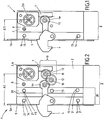
- Fig. 1 is in a plan view of an open pivot bolt lock 1, which is formed according to the construction principle of the invention shown.
- the pivot bolt lock 1 serves to close a door, a window, a gate, a cover element or the like.
- the pivot bolt lock 1 has a lock housing 2, in which a locking mechanism 3 is received.
- the lock housing 2 has a base part 8 and a forend 5.
- At the forend 5 of the pivot bolt 4 of the pivot bolt lock 1 is rotatably held.
- Fig. 1 is the pivot bolt 4 in a retracted position in which the pivot bolt 4 protrudes from the faceplate 5 of the lock housing 2.
- the pivot bolt 4 is movable into a retracted position, in which this is swung back into the lock housing 2.
- the Locking mechanism 3 has at least one activation element 6, which can be activated via an activation movement for moving the pivoting bolt 4.
- a transmission element 7, here in the form of a rack is provided for active connection between the activation element 6 of the locking mechanism 3 and the pivot bolt 4.
- the forend 5 and the base part 8 of the lock housing 2 overlap one another and are fastened to one another in the attachment points 14, 15.
- Such a trained pivot bolt lock 1 has a distance A1 between the locking mechanism 3, in particular the axis of rotation of a lock cylinder, and the front edge 5a of the Stulpes 5. This distance A1 can also be referred to as a backset.
- FIG. 2 shows in a plan view an open pivot bolt lock 1, which is designed according to the inventive design principle, wherein an intermediate housing part 20 between the forend 5 and the base part 8 of the lock housing 2 is provided to increase the distance A2 or the backset of the pivot bolt lock 1. So that the locking mechanism 3 can continue to actuate the pivot bolt 4, an intermediate mechanism 10 is arranged on a receiving geometry of the base part 8.
- This intermediate mechanism 10 has two gears 11, 12, which are rotatably mounted on or via sleeves 13 on the receiving geometry, which is not shown.
- the intermediate mechanism 10 is designed such that it transmits a movement of the at least one transmission element 7 of the locking mechanism 3 unchanged on the pivot bolt 4, in comparison to the transmission of the movement according to Fig. 1 ,
- the gears 11, 12 of the intermediate mechanism 10 are advantageously formed identically. Due to the special mounting of the gears 11, 12 on the receiving geometry 9 of the base part 8 of the lock housing 2, is an unchanged Translation of the movement of the locking mechanism 3 on the pivot bolt 4 possible.
- the intermediate housing part 20 is fastened on one side to the base part 8 and on the other side to the forend 5 of the lock housing 2.
- attachment points 14 of Stulpes 5 and the attachment points 15 of the base member 8 for attachment of the intermediate housing part 20 are arranged in alignment with the attachment points 14 of the Stulpes 5 and the attachment points 15 of the base part 8.
- the attachment points 14, 15, 21 are preferably formed as a through hole, through the corresponding fasteners 16, such as screws, rivets, etc. are hin micsteckbar.
- the backset A2 of the pivot bolt lock 1 can be very easily increased.
- the pivot bolt lock 1 according to Fig. 1 has the pivot bolt lock 1 according to Fig. 2 only an additional intermediate mechanism 10 and an additional intermediate housing part 20. All other components of the pivot bolt lock 1 are in the two embodiments of the pivot bolt locks 1 according to the Fig. 1 and the Fig. 2 identical. As a result, costs can be saved in the production of pivot bolt locks 1 with different mandrel dimensions.
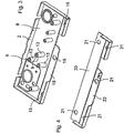
- a base part 8 of a pivot bolt lock 1 is shown in a perspective view, wherein the locking mechanism 3 of the pivot bolt lock 1 is not shown.
- the base part 8 has a special receiving geometry 9, on which the intermediate mechanism 10 can be arranged.
- the intermediate mechanism 10 In Fig. 3 are shown by the intermediate mechanism 10, only the sleeves 13, which are arranged on the receiving geometry 9.
- the receiving geometry 9 may have fastening elements for receiving, in particular rotationally movable, the intermediate mechanism 10.
- the fastening elements of the receiving geometry 9 are formed as pin-shaped projections on which the sleeves 13 of the intermediate mechanism 10 are arranged. It is possible that the sleeves 13 are firmly connected to the receiving geometry 9, in particular with the pin-shaped projections of the receiving geometry 9.
- the gears 11, 12 rotatably supported around the sleeves 13.
- the sleeves 13 can be rotatably mounted on the receiving geometry 9, in particular on the pin-shaped projections of the receiving geometry 9, stored.
- the gears 11, 12 are fixedly connected to the sleeve 13.
- FIG. 4 is a perspective view of a possible embodiment of an intermediate housing part 20 shown.
- the intermediate housing part 20 has attachment points 21, via which the intermediate housing part 20 can be fastened to corresponding attachment points 14 of the cuff 5 or to corresponding attachment points 15 of the base part 8.
- the intermediate housing part 20 has an opening 22, through which the pivot bolt 4 can be pivoted.
- the base 8 according to Fig. 3 has a corresponding opening 18, so that the pivot bolt 4 can be pivoted between a retracted position and a retracted position back and forth.
- Fig. 5 shows in an exploded view a perspective view of a pivot bolt lock 1, which has a forend 5, an intermediate housing part 20 and a base part 8.
- fasteners 16 are shown, which serve for attaching the Stulpes 5 to the intermediate housing part 20 and the intermediate housing part 20 on the base part 8.
- the fastening elements 16 can be, for example, two-part fastening screws or rivets which can be passed through the fastening bores 14 of a fastening profile 5b of the cuff 5, the fastening bores 15 of the base part 8 and the fastening points 21 of the intermediate housing part 20.
- the forend 5 is fastened to the intermediate housing part 20 via a fastening profile 5b.
- the fastening profile 5b is preferably arranged perpendicular to the forend 5 at this.
- the mounting holes 14 are advantageously provided in the mounting profile 5b of the Stulpes 5.
- the fastening profile 5b may be formed integrally, preferably monolithically, with the forend 5.
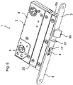
- Fig. 6 shows a pivot bolt lock 1 with an enlarged backset.
- an intermediate housing part 20 is arranged between the base part 8 and the forend 5 of the lock housing 2.
- the mounted inside the lock housing 2 pivot bolt 4 can be brought through the opening 17 in the forend 5 from a retracted position to an extended position in which he protrudes from the forend 5.
- a lock latch 30 is provided in the pivot bolt lock 1, which is formed exchangeable or extendable, in particular has an extendable latch shaft, so that the latch 30 of the pivot bolt lock 1 is adjustable to different mandrel dimensions.
Landscapes
- Engineering & Computer Science (AREA)
- Structural Engineering (AREA)
- Mechanical Engineering (AREA)
- Lock And Its Accessories (AREA)
- Pivots And Pivotal Connections (AREA)
- Wing Frames And Configurations (AREA)
- Hinges (AREA)
Applications Claiming Priority (1)
| Application Number | Priority Date | Filing Date | Title |
|---|---|---|---|
| DE201110000884 DE102011000884A1 (de) | 2011-02-23 | 2011-02-23 | Schwenkriegelschloss für eine Tür, ein Fenster, ein Deckelelement oder dergleichen |
Publications (3)
| Publication Number | Publication Date |
|---|---|
| EP2492419A2 true EP2492419A2 (fr) | 2012-08-29 |
| EP2492419A3 EP2492419A3 (fr) | 2017-11-08 |
| EP2492419B1 EP2492419B1 (fr) | 2019-04-03 |
Family
ID=45654855
Family Applications (1)
| Application Number | Title | Priority Date | Filing Date |
|---|---|---|---|
| EP12000739.8A Active EP2492419B1 (fr) | 2011-02-23 | 2012-02-03 | Pêne pivotant pour une porte, une fenêtre, un élément de toit ou analogue |
Country Status (4)
| Country | Link |
|---|---|
| EP (1) | EP2492419B1 (fr) |
| CN (1) | CN102650178B (fr) |
| DE (1) | DE102011000884A1 (fr) |
| DK (1) | DK2492419T3 (fr) |
Families Citing this family (1)
| Publication number | Priority date | Publication date | Assignee | Title |
|---|---|---|---|---|
| DE102016104596A1 (de) * | 2016-03-14 | 2017-09-14 | Maco Technologie Gmbh | Beschlaganordnung zur Sicherung eines Fensters, einer Tür oder dergleichen an einem Schließblech |
Citations (1)
| Publication number | Priority date | Publication date | Assignee | Title |
|---|---|---|---|---|
| DE102008016699A1 (de) | 2008-03-31 | 2009-10-08 | Dorma Gmbh & Co Kg | Schloss mit einer freigebbaren Dreheinheit |
Family Cites Families (8)
| Publication number | Priority date | Publication date | Assignee | Title |
|---|---|---|---|---|
| DE4337969A1 (de) * | 1993-10-15 | 1995-04-20 | Theodor Krachten | Selbstverriegelndes Sicherheitstürschloß |
| DE19858174C2 (de) * | 1998-12-17 | 2001-05-10 | Dorma Gmbh & Co Kg | Türschloß |
| US7040671B2 (en) * | 2003-01-28 | 2006-05-09 | Jyh-Huey Su, legal representative | Lock assembly with two hook devices |
| CN2809125Y (zh) * | 2005-08-08 | 2006-08-23 | 罗文玲 | 三向双舌门锁 |
| JP5020148B2 (ja) * | 2007-04-06 | 2012-09-05 | トゥルース ハードウェア コーポレイション | 引き戸の二重ロック |
| DE102008009511B4 (de) * | 2008-02-15 | 2016-03-31 | Dorma Deutschland Gmbh | Schloss mit einer verbesserten Schließmechanik |
| CN201232425Y (zh) * | 2008-07-31 | 2009-05-06 | 郭保宣 | 机电智能防盗锁锁体 |
| DE102009006495A1 (de) * | 2009-01-28 | 2010-08-05 | Dorma Gmbh + Co. Kg | Schloss, insbesondere Schwenkriegelschloss, mit erhöhter Schutzwirkung |
-
2011
- 2011-02-23 DE DE201110000884 patent/DE102011000884A1/de not_active Withdrawn
-
2012
- 2012-02-03 EP EP12000739.8A patent/EP2492419B1/fr active Active
- 2012-02-03 DK DK12000739.8T patent/DK2492419T3/da active
- 2012-02-23 CN CN201210043225.6A patent/CN102650178B/zh active Active
Patent Citations (1)
| Publication number | Priority date | Publication date | Assignee | Title |
|---|---|---|---|---|
| DE102008016699A1 (de) | 2008-03-31 | 2009-10-08 | Dorma Gmbh & Co Kg | Schloss mit einer freigebbaren Dreheinheit |
Also Published As
| Publication number | Publication date |
|---|---|
| EP2492419B1 (fr) | 2019-04-03 |
| DK2492419T3 (da) | 2019-07-08 |
| CN102650178B (zh) | 2016-05-18 |
| EP2492419A3 (fr) | 2017-11-08 |
| DE102011000884A1 (de) | 2012-08-23 |
| CN102650178A (zh) | 2012-08-29 |
Similar Documents
| Publication | Publication Date | Title |
|---|---|---|
| DE10103118B4 (de) | Schloss | |
| DE60306654T2 (de) | Türschliessmechanismus | |
| DE102007017453C5 (de) | Drehöffnungsbegrenzungsvorrichtung für einen Flügel eines Fensters oder dergleichen | |
| EP2796645B1 (fr) | Serrure à pêne dormant d'un meuble | |
| DE202012101391U1 (de) | Flügelseitiger Drehflügeltürantriebsanschluss, soweit damit versehene Drehflügeltürantriebsvorrichtung und Drehflügel | |
| DE102012012415A1 (de) | Verriegelungsvorrichtung und damit ausgestattete Flügel bzw. Flügelanlage | |
| DE102008054199B4 (de) | Schloss für Falttore sowie damit versehenes Falttor | |
| EP2492419B1 (fr) | Pêne pivotant pour une porte, une fenêtre, un élément de toit ou analogue | |
| WO2002014634A1 (fr) | Dispositif de securite, par exemple dispositif de securite pour enfants, et dispositif de verrouillage comportant ce dispositif de securite | |
| DE19506430A1 (de) | Schnäpper für eine Drehkipptür | |
| DE202009007430U1 (de) | Beschlagsystem | |
| EP3018269B1 (fr) | Systeme de poignee pour une fenetre ou similaire et fenetre ou similaire dotee du systeme de poignee | |
| DE20316561U1 (de) | Fenster oder Tür | |
| EP1672153B1 (fr) | Serrure avec pêne dormant et dispositif de commande du pêne dormant | |
| EP0930410B1 (fr) | Poignée de manoeuvre | |
| EP2759667A2 (fr) | Dispositif bloque-porte pour un vantail de porte | |
| DE69805942T2 (de) | Vorrichtung für die Betätigung eines Panikschlosses von aussen | |
| EP3553260B1 (fr) | Feuillure avec position de jour pour libération conditionnelle d'un bec de cane d'un mécanisme de fermeture de porte | |
| DE10013697A1 (de) | Feststellvorrichtung | |
| DE202011103191U1 (de) | Selbstverriegelndes Schloss | |
| DE202021100558U1 (de) | Verriegelungseinrichtung für ein Betätigungshandhabenpaar einer Tür | |
| EP4253698B1 (fr) | Système de fermeture pour une porte et agencement de porte doté d'un système de fermeture | |
| EP3892802B1 (fr) | Agencement de poignée de porte | |
| EP1961895A2 (fr) | Ferrure de porte | |
| EP1790805B1 (fr) | Mécanisme d'actionnement à levier pour une crémone |
Legal Events
| Date | Code | Title | Description |
|---|---|---|---|
| PUAI | Public reference made under article 153(3) epc to a published international application that has entered the european phase |
Free format text: ORIGINAL CODE: 0009012 |
|
| AK | Designated contracting states |
Kind code of ref document: A2 Designated state(s): AL AT BE BG CH CY CZ DE DK EE ES FI FR GB GR HR HU IE IS IT LI LT LU LV MC MK MT NL NO PL PT RO RS SE SI SK SM TR |
|
| AX | Request for extension of the european patent |
Extension state: BA ME |
|
| RAP1 | Party data changed (applicant data changed or rights of an application transferred) |
Owner name: DORMA DEUTSCHLAND GMBH |
|
| RAP1 | Party data changed (applicant data changed or rights of an application transferred) |
Owner name: DORMAKABA DEUTSCHLAND GMBH |
|
| PUAL | Search report despatched |
Free format text: ORIGINAL CODE: 0009013 |
|
| AK | Designated contracting states |
Kind code of ref document: A3 Designated state(s): AL AT BE BG CH CY CZ DE DK EE ES FI FR GB GR HR HU IE IS IT LI LT LU LV MC MK MT NL NO PL PT RO RS SE SI SK SM TR |
|
| AX | Request for extension of the european patent |
Extension state: BA ME |
|
| RIC1 | Information provided on ipc code assigned before grant |
Ipc: E05B 63/06 20060101ALI20171004BHEP Ipc: E05B 47/00 20060101ALI20171004BHEP Ipc: E05B 9/00 20060101ALI20171004BHEP Ipc: E05B 9/06 20060101AFI20171004BHEP |
|
| STAA | Information on the status of an ep patent application or granted ep patent |
Free format text: STATUS: REQUEST FOR EXAMINATION WAS MADE |
|
| 17P | Request for examination filed |
Effective date: 20180405 |
|
| RBV | Designated contracting states (corrected) |
Designated state(s): AL AT BE BG CH CY CZ DE DK EE ES FI FR GB GR HR HU IE IS IT LI LT LU LV MC MK MT NL NO PL PT RO RS SE SI SK SM TR |
|
| GRAP | Despatch of communication of intention to grant a patent |
Free format text: ORIGINAL CODE: EPIDOSNIGR1 |
|
| STAA | Information on the status of an ep patent application or granted ep patent |
Free format text: STATUS: GRANT OF PATENT IS INTENDED |
|
| INTG | Intention to grant announced |
Effective date: 20180906 |
|
| GRAS | Grant fee paid |
Free format text: ORIGINAL CODE: EPIDOSNIGR3 |
|
| GRAA | (expected) grant |
Free format text: ORIGINAL CODE: 0009210 |
|
| STAA | Information on the status of an ep patent application or granted ep patent |
Free format text: STATUS: THE PATENT HAS BEEN GRANTED |
|
| AK | Designated contracting states |
Kind code of ref document: B1 Designated state(s): AL AT BE BG CH CY CZ DE DK EE ES FI FR GB GR HR HU IE IS IT LI LT LU LV MC MK MT NL NO PL PT RO RS SE SI SK SM TR |
|
| REG | Reference to a national code |
Ref country code: GB Ref legal event code: FG4D Free format text: NOT ENGLISH |
|
| REG | Reference to a national code |
Ref country code: CH Ref legal event code: EP Ref country code: AT Ref legal event code: REF Ref document number: 1115921 Country of ref document: AT Kind code of ref document: T Effective date: 20190415 |
|
| REG | Reference to a national code |
Ref country code: DE Ref legal event code: R096 Ref document number: 502012014515 Country of ref document: DE |
|
| REG | Reference to a national code |
Ref country code: IE Ref legal event code: FG4D Free format text: LANGUAGE OF EP DOCUMENT: GERMAN |
|
| REG | Reference to a national code |
Ref country code: DK Ref legal event code: T3 Effective date: 20190704 |
|
| REG | Reference to a national code |
Ref country code: SE Ref legal event code: TRGR |
|
| REG | Reference to a national code |
Ref country code: NL Ref legal event code: MP Effective date: 20190403 |
|
| REG | Reference to a national code |
Ref country code: LT Ref legal event code: MG4D |
|
| REG | Reference to a national code |
Ref country code: NO Ref legal event code: T2 Effective date: 20190403 |
|
| PG25 | Lapsed in a contracting state [announced via postgrant information from national office to epo] |
Ref country code: NL Free format text: LAPSE BECAUSE OF FAILURE TO SUBMIT A TRANSLATION OF THE DESCRIPTION OR TO PAY THE FEE WITHIN THE PRESCRIBED TIME-LIMIT Effective date: 20190403 |
|
| PG25 | Lapsed in a contracting state [announced via postgrant information from national office to epo] |
Ref country code: LT Free format text: LAPSE BECAUSE OF FAILURE TO SUBMIT A TRANSLATION OF THE DESCRIPTION OR TO PAY THE FEE WITHIN THE PRESCRIBED TIME-LIMIT Effective date: 20190403 Ref country code: AL Free format text: LAPSE BECAUSE OF FAILURE TO SUBMIT A TRANSLATION OF THE DESCRIPTION OR TO PAY THE FEE WITHIN THE PRESCRIBED TIME-LIMIT Effective date: 20190403 Ref country code: PT Free format text: LAPSE BECAUSE OF FAILURE TO SUBMIT A TRANSLATION OF THE DESCRIPTION OR TO PAY THE FEE WITHIN THE PRESCRIBED TIME-LIMIT Effective date: 20190803 Ref country code: ES Free format text: LAPSE BECAUSE OF FAILURE TO SUBMIT A TRANSLATION OF THE DESCRIPTION OR TO PAY THE FEE WITHIN THE PRESCRIBED TIME-LIMIT Effective date: 20190403 Ref country code: CZ Free format text: LAPSE BECAUSE OF FAILURE TO SUBMIT A TRANSLATION OF THE DESCRIPTION OR TO PAY THE FEE WITHIN THE PRESCRIBED TIME-LIMIT Effective date: 20190403 Ref country code: HR Free format text: LAPSE BECAUSE OF FAILURE TO SUBMIT A TRANSLATION OF THE DESCRIPTION OR TO PAY THE FEE WITHIN THE PRESCRIBED TIME-LIMIT Effective date: 20190403 |
|
| PG25 | Lapsed in a contracting state [announced via postgrant information from national office to epo] |
Ref country code: RS Free format text: LAPSE BECAUSE OF FAILURE TO SUBMIT A TRANSLATION OF THE DESCRIPTION OR TO PAY THE FEE WITHIN THE PRESCRIBED TIME-LIMIT Effective date: 20190403 Ref country code: LV Free format text: LAPSE BECAUSE OF FAILURE TO SUBMIT A TRANSLATION OF THE DESCRIPTION OR TO PAY THE FEE WITHIN THE PRESCRIBED TIME-LIMIT Effective date: 20190403 Ref country code: PL Free format text: LAPSE BECAUSE OF FAILURE TO SUBMIT A TRANSLATION OF THE DESCRIPTION OR TO PAY THE FEE WITHIN THE PRESCRIBED TIME-LIMIT Effective date: 20190403 Ref country code: GR Free format text: LAPSE BECAUSE OF FAILURE TO SUBMIT A TRANSLATION OF THE DESCRIPTION OR TO PAY THE FEE WITHIN THE PRESCRIBED TIME-LIMIT Effective date: 20190704 Ref country code: BG Free format text: LAPSE BECAUSE OF FAILURE TO SUBMIT A TRANSLATION OF THE DESCRIPTION OR TO PAY THE FEE WITHIN THE PRESCRIBED TIME-LIMIT Effective date: 20190703 |
|
| PG25 | Lapsed in a contracting state [announced via postgrant information from national office to epo] |
Ref country code: IS Free format text: LAPSE BECAUSE OF FAILURE TO SUBMIT A TRANSLATION OF THE DESCRIPTION OR TO PAY THE FEE WITHIN THE PRESCRIBED TIME-LIMIT Effective date: 20190803 |
|
| REG | Reference to a national code |
Ref country code: DE Ref legal event code: R097 Ref document number: 502012014515 Country of ref document: DE |
|
| PG25 | Lapsed in a contracting state [announced via postgrant information from national office to epo] |
Ref country code: EE Free format text: LAPSE BECAUSE OF FAILURE TO SUBMIT A TRANSLATION OF THE DESCRIPTION OR TO PAY THE FEE WITHIN THE PRESCRIBED TIME-LIMIT Effective date: 20190403 Ref country code: RO Free format text: LAPSE BECAUSE OF FAILURE TO SUBMIT A TRANSLATION OF THE DESCRIPTION OR TO PAY THE FEE WITHIN THE PRESCRIBED TIME-LIMIT Effective date: 20190403 Ref country code: SK Free format text: LAPSE BECAUSE OF FAILURE TO SUBMIT A TRANSLATION OF THE DESCRIPTION OR TO PAY THE FEE WITHIN THE PRESCRIBED TIME-LIMIT Effective date: 20190403 |
|
| PLBE | No opposition filed within time limit |
Free format text: ORIGINAL CODE: 0009261 |
|
| STAA | Information on the status of an ep patent application or granted ep patent |
Free format text: STATUS: NO OPPOSITION FILED WITHIN TIME LIMIT |
|
| PG25 | Lapsed in a contracting state [announced via postgrant information from national office to epo] |
Ref country code: IT Free format text: LAPSE BECAUSE OF FAILURE TO SUBMIT A TRANSLATION OF THE DESCRIPTION OR TO PAY THE FEE WITHIN THE PRESCRIBED TIME-LIMIT Effective date: 20190403 Ref country code: SM Free format text: LAPSE BECAUSE OF FAILURE TO SUBMIT A TRANSLATION OF THE DESCRIPTION OR TO PAY THE FEE WITHIN THE PRESCRIBED TIME-LIMIT Effective date: 20190403 |
|
| 26N | No opposition filed |
Effective date: 20200106 |
|
| PG25 | Lapsed in a contracting state [announced via postgrant information from national office to epo] |
Ref country code: TR Free format text: LAPSE BECAUSE OF FAILURE TO SUBMIT A TRANSLATION OF THE DESCRIPTION OR TO PAY THE FEE WITHIN THE PRESCRIBED TIME-LIMIT Effective date: 20190403 |
|
| PG25 | Lapsed in a contracting state [announced via postgrant information from national office to epo] |
Ref country code: SI Free format text: LAPSE BECAUSE OF FAILURE TO SUBMIT A TRANSLATION OF THE DESCRIPTION OR TO PAY THE FEE WITHIN THE PRESCRIBED TIME-LIMIT Effective date: 20190403 |
|
| REG | Reference to a national code |
Ref country code: DE Ref legal event code: R119 Ref document number: 502012014515 Country of ref document: DE |
|
| REG | Reference to a national code |
Ref country code: CH Ref legal event code: PL |
|
| GBPC | Gb: european patent ceased through non-payment of renewal fee |
Effective date: 20200203 |
|
| REG | Reference to a national code |
Ref country code: BE Ref legal event code: MM Effective date: 20200229 |
|
| PG25 | Lapsed in a contracting state [announced via postgrant information from national office to epo] |
Ref country code: LU Free format text: LAPSE BECAUSE OF NON-PAYMENT OF DUE FEES Effective date: 20200203 Ref country code: MC Free format text: LAPSE BECAUSE OF FAILURE TO SUBMIT A TRANSLATION OF THE DESCRIPTION OR TO PAY THE FEE WITHIN THE PRESCRIBED TIME-LIMIT Effective date: 20190403 |
|
| PG25 | Lapsed in a contracting state [announced via postgrant information from national office to epo] |
Ref country code: LI Free format text: LAPSE BECAUSE OF NON-PAYMENT OF DUE FEES Effective date: 20200229 Ref country code: CH Free format text: LAPSE BECAUSE OF NON-PAYMENT OF DUE FEES Effective date: 20200229 |
|
| PG25 | Lapsed in a contracting state [announced via postgrant information from national office to epo] |
Ref country code: GB Free format text: LAPSE BECAUSE OF NON-PAYMENT OF DUE FEES Effective date: 20200203 Ref country code: IE Free format text: LAPSE BECAUSE OF NON-PAYMENT OF DUE FEES Effective date: 20200203 Ref country code: DE Free format text: LAPSE BECAUSE OF NON-PAYMENT OF DUE FEES Effective date: 20200901 Ref country code: FR Free format text: LAPSE BECAUSE OF NON-PAYMENT OF DUE FEES Effective date: 20200229 |
|
| PG25 | Lapsed in a contracting state [announced via postgrant information from national office to epo] |
Ref country code: BE Free format text: LAPSE BECAUSE OF NON-PAYMENT OF DUE FEES Effective date: 20200229 |
|
| REG | Reference to a national code |
Ref country code: AT Ref legal event code: MM01 Ref document number: 1115921 Country of ref document: AT Kind code of ref document: T Effective date: 20200203 |
|
| PG25 | Lapsed in a contracting state [announced via postgrant information from national office to epo] |
Ref country code: AT Free format text: LAPSE BECAUSE OF NON-PAYMENT OF DUE FEES Effective date: 20200203 |
|
| PG25 | Lapsed in a contracting state [announced via postgrant information from national office to epo] |
Ref country code: MT Free format text: LAPSE BECAUSE OF FAILURE TO SUBMIT A TRANSLATION OF THE DESCRIPTION OR TO PAY THE FEE WITHIN THE PRESCRIBED TIME-LIMIT Effective date: 20190403 Ref country code: CY Free format text: LAPSE BECAUSE OF FAILURE TO SUBMIT A TRANSLATION OF THE DESCRIPTION OR TO PAY THE FEE WITHIN THE PRESCRIBED TIME-LIMIT Effective date: 20190403 |
|
| PG25 | Lapsed in a contracting state [announced via postgrant information from national office to epo] |
Ref country code: MK Free format text: LAPSE BECAUSE OF FAILURE TO SUBMIT A TRANSLATION OF THE DESCRIPTION OR TO PAY THE FEE WITHIN THE PRESCRIBED TIME-LIMIT Effective date: 20190403 |
|
| PGFP | Annual fee paid to national office [announced via postgrant information from national office to epo] |
Ref country code: SE Payment date: 20260218 Year of fee payment: 15 |
|
| PGFP | Annual fee paid to national office [announced via postgrant information from national office to epo] |
Ref country code: NO Payment date: 20260220 Year of fee payment: 15 Ref country code: DK Payment date: 20260220 Year of fee payment: 15 |
|
| PGFP | Annual fee paid to national office [announced via postgrant information from national office to epo] |
Ref country code: FI Payment date: 20260226 Year of fee payment: 15 |