EP2492419A2 - Pivoting deadlock for a door, window, covering element or the like - Google Patents
Pivoting deadlock for a door, window, covering element or the like Download PDFInfo
- Publication number
- EP2492419A2 EP2492419A2 EP12000739A EP12000739A EP2492419A2 EP 2492419 A2 EP2492419 A2 EP 2492419A2 EP 12000739 A EP12000739 A EP 12000739A EP 12000739 A EP12000739 A EP 12000739A EP 2492419 A2 EP2492419 A2 EP 2492419A2
- Authority
- EP
- European Patent Office
- Prior art keywords
- pivot bolt
- lock
- base part
- housing
- locking mechanism
- Prior art date
- Legal status (The legal status is an assumption and is not a legal conclusion. Google has not performed a legal analysis and makes no representation as to the accuracy of the status listed.)
- Granted
Links
Images

Classifications
-
- E—FIXED CONSTRUCTIONS
- E05—LOCKS; KEYS; WINDOW OR DOOR FITTINGS; SAFES
- E05B—LOCKS; ACCESSORIES THEREFOR; HANDCUFFS
- E05B63/00—Locks or fastenings with special structural characteristics
- E05B63/0056—Locks with adjustable or exchangeable lock parts
-
- E—FIXED CONSTRUCTIONS
- E05—LOCKS; KEYS; WINDOW OR DOOR FITTINGS; SAFES
- E05B—LOCKS; ACCESSORIES THEREFOR; HANDCUFFS
- E05B17/00—Accessories in connection with locks
- E05B17/04—Devices for coupling the turning cylinder of a single or a double cylinder lock with the bolt operating member
- E05B17/042—Devices for coupling the turning cylinder of a single or a double cylinder lock with the bolt operating member using toothed wheels or geared sectors
-
- E—FIXED CONSTRUCTIONS
- E05—LOCKS; KEYS; WINDOW OR DOOR FITTINGS; SAFES
- E05B—LOCKS; ACCESSORIES THEREFOR; HANDCUFFS
- E05B63/00—Locks or fastenings with special structural characteristics
- E05B63/06—Locks or fastenings with special structural characteristics with lengthwise-adjustable bolts ; with adjustable backset, i.e. distance from door edge
-
- E—FIXED CONSTRUCTIONS
- E05—LOCKS; KEYS; WINDOW OR DOOR FITTINGS; SAFES
- E05B—LOCKS; ACCESSORIES THEREFOR; HANDCUFFS
- E05B9/00—Lock casings or latch-mechanism casings ; Fastening locks or fasteners or parts thereof to the wing
- E05B9/02—Casings of latch-bolt or deadbolt locks
-
- E—FIXED CONSTRUCTIONS
- E05—LOCKS; KEYS; WINDOW OR DOOR FITTINGS; SAFES
- E05B—LOCKS; ACCESSORIES THEREFOR; HANDCUFFS
- E05B63/00—Locks or fastenings with special structural characteristics
- E05B63/0013—Locks with rotary bolt without provision for latching
Definitions
- the present invention relates to a lock bolt lock for a door, a window, a cover member or the like, with a lock housing, in which at least one locking mechanism is received with a pivot bolt, wherein the pivot bolt is movable to an extended position in which the pivot bolt from a forend the latch housing protruding, and wherein the pivot bolt is movable to a retracted position in which the pivot bolt is moved back into the lock housing, wherein the locking mechanism has at least one activating element which can be activated via an activating movement for moving the pivot bolt, and wherein the operative connection between the Activation element and the pivot bolt comprises at least one transmission element.
- pivot bolt locks pivots when closing the pivot bolt out of the lock housing. That is, in the retracted position, the pivot bolt may close a door, a window, a gate, a lid member, or the like. In the retracted position, the pivot bolt is in the lock housing such that a door, a window, a gate, a cover member or the like, in which the pivot bolt lock is installed, can be opened.
- the pivot bolt is usually longer than the bolt of conventional locks, in which the bolt for closing the door, the window, the door or the cover element is moved out.
- a lock which is designed as a pivot bolt lock.
- a lock is used for doors, gates, windows or the like.
- the pivot bolt is as a hook latch executed and is pivotally received in the lock housing of the pivot bolt lock. If the pivot bolt is pivoted out of the lock housing and protrudes therefrom, the pivot bolt can engage with a complementarily designed counter element to close the door, the gate, the window or the like.
- the pivot bolt lock is unlocked by an activation element, for example by a handle or by a lock cylinder, the pivot bolt can be transferred from the retracted position to the retracted position.
- the activation element for activating the locking mechanism of the pivot bolt lock and consequently for moving the pivot bolt is formed in particular by a handle, such as a door handle or a door knob, or by a lock cylinder.
- Swing bolt locks can be designed in different mandrel dimensions.
- the backset specifies the distance from the center of the door handle or the keyhole, that is, the axis of rotation of the cylinder, to the forend.
- Swing bolt locks are available with different backset dimensions. Usual spine measurements are 25 mm to 100 mm.
- Different sized pivot bolt locks are required. The disadvantage here is that the different sized pivot bolt locks must be made individually.
- Object of the present invention is to provide a pivot bolt lock, which has a flexible backset.
- a pivot bolt lock is to be created, which can be rebuilt with little installation effort, so that the backset of the pivot bolt lock can increase or decrease.
- a pivot bolt lock for a door, preferably a building door, a window, a cover element or the like with a lock housing, in which at least one locking mechanism is received with a pivot bolt.
- the pivot bolt of the pivot bolt latch is movable to a deployed position in which the pivot latch protrudes from a cuff of the latch housing, and the pivot latch is movable to a retracted position in which the pivot latch is moved back into the latch housing.
- the locking mechanism of the pivot bolt lock has at least one activation element, which can be activated via an activation movement for moving the pivot bolt, wherein the operative connection between the activation element and the pivot bolt comprises at least one transmission element, wherein the lock housing has a base part.
- the pivot bolt is rotatably held on the forend of the pivot bolt lock and at least one intermediate housing part can be fastened for variable enlargement of the distance between the locking mechanism and the front edge of the Stulpes between the base part and the forend.
- a receiving geometry for the arrangement of an intermediate mechanism is arranged on the base part of the lock housing, which is designed for mechanical coupling of the locking mechanism with the locking bolt.
- the pivot bolt can advantageously be designed as a hook bolt.
- the pivot bolt In the retracted position, the pivot bolt can close a door, a window, a gate, a cover element or the like. In the retracted position, the pivot bolt is arranged in the lock housing such that a door, a window, a gate, a cover element or the like, in which the pivot bolt lock is installed, can be opened.
- Such a trained pivot bolt lock allows to enlarge the backset of the pivot bolt lock. That is, to increase the distance between the locking mechanism, in particular the axis of rotation of the lock cylinder, and the Stulpvorderkante at least one intermediate housing part can be inserted.
- an intermediate mechanism can be arranged, which is designed for mechanical coupling of the locking mechanism and the pivot bolt.
- the intermediate mechanism is arranged between the locking mechanism and the pivot bolt.
- the intermediate mechanism acts both on the locking mechanism and on the pivot bolt, so that via an activating movement, such as a handle, the at least one activation element of the locking mechanism of the pivot bolt can be pivoted to the same extent as in a direct engagement of the locking mechanism on the pivot bolt ,
- An advantage of such a trained pivot bolt lock is that this can be realized with different sized distances between the locking mechanism and the Stulpvorderkante, that is different sized mandrel sizes, using as many common parts. That is, to create from a pivot bolt lock with a smaller backset a pivot bolt lock with a larger backset, only at least one intermediate housing part and a corresponding intermediate mechanism are required.
- Such a trained lock bolt lock creates a large redundancy. That is, swing bolt locks with different spine dimensions point to Most of the same components. There are only small changes, in particular additions of fewer parts, required to produce swing bolt locks with different sized mandrel dimensions.
- the intermediate mechanism By the intermediate mechanism, the activation movement of the at least one activation element of the locking mechanism is transmitted to the pivot bolt.
- at least one transmission element and optionally an intermediate mechanism is required for active connection between the activation element of the locking mechanism and the pivot bolt.
- an intermediate mechanism is required for active connection between the activation element of the locking mechanism and the pivot bolt.
- the intermediate mechanism is designed such that a movement of the at least one transmission element of the locking mechanism via the intermediate mechanism unchanged on the pivot bolt is transferable. That is, the intermediate mechanism is designed such that the translation of the locking mechanism remains maintained on the pivot bolt by the intermediate mechanism.
- the direction of rotation or the direction of rotation of the locking mechanism with and without the intermediate mechanism is always the same to move the pivot bolt back and forth. This can be realized by the special receiving geometry on the base part of the lock housing and the intermediate mechanism attachable thereto.
- a pivot bolt lock in which the pivot bolt has a toothed segment or a tooth structure for selectively engaging the at least one transmission element of the locking mechanism or the intermediate mechanism. That is, both the at least one transmission element of the locking mechanism and the intermediate mechanism are designed such that they can equally engage in the toothed segment or the tooth structure of the pivot bolt in order to pivot the pivot bolt.
- the pivot bolt is rotatably mounted on the forend of the pivot bolt lock.
- the at least one transmission element of the lock mechanism a rack or a tooth structure, in particular a gear or a ring gear, for actuating the pivot bolt, in particular the toothed segment of the pivot bolt, or for actuating the intermediate mechanism includes.
- the rack or the tooth structure is manually or automatically movable to cause the pivoting of the pivot bolt by a movement of the rack or the tooth structure.
- further transmission elements may be provided, which are coupled together to forward a triggered by an activation element activation movement on the pivot bolt.
- the intermediate mechanism comprises at least two gears, which are rotatably mounted on the receiving geometry on the base part of the lock housing.
- the gears are preferably identical.
- the two gears are movably mounted on the receiving geometry on the base part of the lock housing such that they engage with each other.
- One of the gears is in direct operative contact with the locking mechanism, in particular to the at least one transmission element of the locking mechanism, whereas the other gear is in direct engagement with the pivot bolt, in particular the toothed segment of the pivot bolt.
- the receiving geometry Fastening elements for receiving, in particular rotatable recording, the intermediate mechanism has.
- the receiving geometry on the base part of the lock housing is designed such that it is not hindering the direct engagement of the at least one transmission element of the locking mechanism on the pivot bolt.
- the fastening elements of the receiving geometry can fix, for example, a part of the intermediate mechanism, whereas a further part of the intermediate mechanism remains movable.
- the fastening elements can also be designed such that all elements of the intermediate mechanism are movably mounted in the fastening elements.
- the fasteners holes and / or pin-shaped projections for receiving, in particular rotatable recording, the intermediate mechanism.
- the fastening elements are designed as bores, they can, for example, accommodate axes of the intermediate mechanism. If the fastening elements are designed as pin-shaped projections, corresponding, provided with blind holes axes can be attached to these rotatably.
- a pivot bolt lock is preferred in which the at least two gears of the intermediate mechanism are rotatably held in the bores and / or on the pin-shaped projections of the receiving geometry.
- pins or sleeves are provided, which are designed for rotatably supporting the at least two gears on the receiving geometry, in particular fastened or mounted.
- the pins or sleeves attached to the fasteners and the at least two gears of the intermediate mechanism can be rotatably mounted on the pin or sleeves.
- the at least two gears the intermediate mechanism fixedly secured to the pins and sleeves and the pins or sleeves are rotatably mounted on the fasteners.
- Such a trained pivot bolt lock allows the subsequent arrangement of the intermediate mechanism on the receiving geometry of the base part of the lock housing, so that the pivot bolt lock by the attached intermediate mechanism and the at least one intermediate housing part between the forend and the base part of the lock housing is simple, inexpensive and quickly expandable.
- the distance between the locking mechanism, that is, the axis of rotation of the lock cylinder, and the Stulpvorderkante the backset of the pivot bolt lock By adding the intermediate mechanism and the at least one intermediate housing part, the backset of the pivot bolt lock can be flexibly changed, in particular widened. Depending on the design of the receiving geometry and the size of the gears, the backset can be varied differently.
- the base part may have such a receiving geometry that it is designed to accommodate gear pairs of different sizes.
- a plurality of fastening elements may be provided for receiving different sized intermediate mechanisms.
- the invention may be provided in a pivot bolt lock that the change in the distance between the locking mechanism and the Stulpvorderkante, that is, the change in the backset of the pivot bolt lock, the width of the at least one intermediate housing part corresponds. In this way it can be ensured that the lock housing of the pivot bolt lock remains closed when mounting at least one intermediate housing part.
- the at least one intermediate housing part can be variously connected to the base part and the forend.
- the at least one intermediate housing part can be attached to the base part and the forend in a positive and / or non-positive manner.
- the attachment of the at least one intermediate housing part to the base part and to the forend can be realized by screw connections.
- pin or rivet connections can be used for attachment.
- fastening points, in particular fastening bores, of the at least one intermediate housing part can be arranged in alignment with attachment points, in particular fastening bores, of the cuff and of the base part. That is, the at least one intermediate housing part can be arranged at the same attachment points of the cuff and the base part, which also serve for the direct connection of the cuff and the base part.
- a pivot bolt lock that two or more intermediate housing parts in series between the base part and the forend can be arranged.
- the distance between the Stulpvorderkante and the locking mechanism, that is, the backset of the pivot bolt lock variably changed, in particular, be increased.
- the locking mechanism can transmit the activation movement via the intermediate mechanism unchanged to the pivot bolt.
- a pivot bolt lock Preferably may be additionally provided in a pivot bolt lock that this has a latch and / or an additional trap, the is designed extensible or replaceable.
- an elongated lock latch can be mounted, wherein the lock latch is mounted linearly movable in the lock housing of the pivot bolt lock.
- the latch shaft of the latch can be extended and a correspondingly larger spring can be used.
- the preferably spring-loaded additional case can move out of the lock housing or move into the lock housing.
- the additional case can be designed as a longitudinally movable part, which is longitudinally movably guided over a slot-pin arrangement in the lock housing.
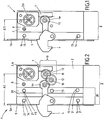
- Fig. 1 is in a plan view of an open pivot bolt lock 1, which is formed according to the construction principle of the invention shown.
- the pivot bolt lock 1 serves to close a door, a window, a gate, a cover element or the like.
- the pivot bolt lock 1 has a lock housing 2, in which a locking mechanism 3 is received.
- the lock housing 2 has a base part 8 and a forend 5.
- At the forend 5 of the pivot bolt 4 of the pivot bolt lock 1 is rotatably held.
- Fig. 1 is the pivot bolt 4 in a retracted position in which the pivot bolt 4 protrudes from the faceplate 5 of the lock housing 2.
- the pivot bolt 4 is movable into a retracted position, in which this is swung back into the lock housing 2.
- the Locking mechanism 3 has at least one activation element 6, which can be activated via an activation movement for moving the pivoting bolt 4.
- a transmission element 7, here in the form of a rack is provided for active connection between the activation element 6 of the locking mechanism 3 and the pivot bolt 4.
- the forend 5 and the base part 8 of the lock housing 2 overlap one another and are fastened to one another in the attachment points 14, 15.
- Such a trained pivot bolt lock 1 has a distance A1 between the locking mechanism 3, in particular the axis of rotation of a lock cylinder, and the front edge 5a of the Stulpes 5. This distance A1 can also be referred to as a backset.
- FIG. 2 shows in a plan view an open pivot bolt lock 1, which is designed according to the inventive design principle, wherein an intermediate housing part 20 between the forend 5 and the base part 8 of the lock housing 2 is provided to increase the distance A2 or the backset of the pivot bolt lock 1. So that the locking mechanism 3 can continue to actuate the pivot bolt 4, an intermediate mechanism 10 is arranged on a receiving geometry of the base part 8.
- This intermediate mechanism 10 has two gears 11, 12, which are rotatably mounted on or via sleeves 13 on the receiving geometry, which is not shown.
- the intermediate mechanism 10 is designed such that it transmits a movement of the at least one transmission element 7 of the locking mechanism 3 unchanged on the pivot bolt 4, in comparison to the transmission of the movement according to Fig. 1 ,
- the gears 11, 12 of the intermediate mechanism 10 are advantageously formed identically. Due to the special mounting of the gears 11, 12 on the receiving geometry 9 of the base part 8 of the lock housing 2, is an unchanged Translation of the movement of the locking mechanism 3 on the pivot bolt 4 possible.
- the intermediate housing part 20 is fastened on one side to the base part 8 and on the other side to the forend 5 of the lock housing 2.
- attachment points 14 of Stulpes 5 and the attachment points 15 of the base member 8 for attachment of the intermediate housing part 20 are arranged in alignment with the attachment points 14 of the Stulpes 5 and the attachment points 15 of the base part 8.
- the attachment points 14, 15, 21 are preferably formed as a through hole, through the corresponding fasteners 16, such as screws, rivets, etc. are hin micsteckbar.
- the backset A2 of the pivot bolt lock 1 can be very easily increased.
- the pivot bolt lock 1 according to Fig. 1 has the pivot bolt lock 1 according to Fig. 2 only an additional intermediate mechanism 10 and an additional intermediate housing part 20. All other components of the pivot bolt lock 1 are in the two embodiments of the pivot bolt locks 1 according to the Fig. 1 and the Fig. 2 identical. As a result, costs can be saved in the production of pivot bolt locks 1 with different mandrel dimensions.
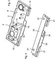
- a base part 8 of a pivot bolt lock 1 is shown in a perspective view, wherein the locking mechanism 3 of the pivot bolt lock 1 is not shown.
- the base part 8 has a special receiving geometry 9, on which the intermediate mechanism 10 can be arranged.
- the intermediate mechanism 10 In Fig. 3 are shown by the intermediate mechanism 10, only the sleeves 13, which are arranged on the receiving geometry 9.
- the receiving geometry 9 may have fastening elements for receiving, in particular rotationally movable, the intermediate mechanism 10.
- the fastening elements of the receiving geometry 9 are formed as pin-shaped projections on which the sleeves 13 of the intermediate mechanism 10 are arranged. It is possible that the sleeves 13 are firmly connected to the receiving geometry 9, in particular with the pin-shaped projections of the receiving geometry 9.
- the gears 11, 12 rotatably supported around the sleeves 13.
- the sleeves 13 can be rotatably mounted on the receiving geometry 9, in particular on the pin-shaped projections of the receiving geometry 9, stored.
- the gears 11, 12 are fixedly connected to the sleeve 13.
- FIG. 4 is a perspective view of a possible embodiment of an intermediate housing part 20 shown.
- the intermediate housing part 20 has attachment points 21, via which the intermediate housing part 20 can be fastened to corresponding attachment points 14 of the cuff 5 or to corresponding attachment points 15 of the base part 8.
- the intermediate housing part 20 has an opening 22, through which the pivot bolt 4 can be pivoted.
- the base 8 according to Fig. 3 has a corresponding opening 18, so that the pivot bolt 4 can be pivoted between a retracted position and a retracted position back and forth.
- Fig. 5 shows in an exploded view a perspective view of a pivot bolt lock 1, which has a forend 5, an intermediate housing part 20 and a base part 8.
- fasteners 16 are shown, which serve for attaching the Stulpes 5 to the intermediate housing part 20 and the intermediate housing part 20 on the base part 8.
- the fastening elements 16 can be, for example, two-part fastening screws or rivets which can be passed through the fastening bores 14 of a fastening profile 5b of the cuff 5, the fastening bores 15 of the base part 8 and the fastening points 21 of the intermediate housing part 20.
- the forend 5 is fastened to the intermediate housing part 20 via a fastening profile 5b.
- the fastening profile 5b is preferably arranged perpendicular to the forend 5 at this.
- the mounting holes 14 are advantageously provided in the mounting profile 5b of the Stulpes 5.
- the fastening profile 5b may be formed integrally, preferably monolithically, with the forend 5.
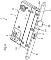
- Fig. 6 shows a pivot bolt lock 1 with an enlarged backset.
- an intermediate housing part 20 is arranged between the base part 8 and the forend 5 of the lock housing 2.
- the mounted inside the lock housing 2 pivot bolt 4 can be brought through the opening 17 in the forend 5 from a retracted position to an extended position in which he protrudes from the forend 5.
- a lock latch 30 is provided in the pivot bolt lock 1, which is formed exchangeable or extendable, in particular has an extendable latch shaft, so that the latch 30 of the pivot bolt lock 1 is adjustable to different mandrel dimensions.
Landscapes
- Engineering & Computer Science (AREA)
- Structural Engineering (AREA)
- Mechanical Engineering (AREA)
- Lock And Its Accessories (AREA)
- Pivots And Pivotal Connections (AREA)
- Wing Frames And Configurations (AREA)
- Hinges (AREA)
Abstract
Description
Die vorliegende Erfindung betrifft ein Schwenkriegelschloss für eine Tür, ein Fenster, ein Deckelelement oder dergleichen, mit einem Schlossgehäuse, in dem wenigstens eine Schließmechanik mit einem Schwenkriegel aufgenommen ist, wobei der Schwenkriegel in eine herausgefahrene Position bewegbar ist, in der der Schwenkriegel aus einem Stulp des Schlossgehäuses hervorsteht, und wobei der Schwenkriegel in eine eingefahrene Position bewegbar ist, in der der Schwenkriegel in das Schlossgehäuse zurückbewegt ist, wobei die Schließmechanik zumindest ein Aktivierungselement aufweist, das über eine Aktivierungsbewegung zum Bewegen des Schwenkriegels aktivierbar ist, und wobei die Wirkverbindung zwischen dem Aktivierungselement und dem Schwenkriegel zumindest ein Getriebeelement umfasst.The present invention relates to a lock bolt lock for a door, a window, a cover member or the like, with a lock housing, in which at least one locking mechanism is received with a pivot bolt, wherein the pivot bolt is movable to an extended position in which the pivot bolt from a forend the latch housing protruding, and wherein the pivot bolt is movable to a retracted position in which the pivot bolt is moved back into the lock housing, wherein the locking mechanism has at least one activating element which can be activated via an activating movement for moving the pivot bolt, and wherein the operative connection between the Activation element and the pivot bolt comprises at least one transmission element.
Bei Schwenkriegelschlössern schwenkt beim Abschließen der Schwenkriegel aus dem Schlossgehäuse heraus. Das heißt, in der herausgefahrenen Position kann der Schwenkriegel eine Tür, ein Fenster, ein Tor, ein Deckelelement oder dergleichen verschließen. In der eingefahrenen Position befindet sich der Schwenkriegel derart im Schlossgehäuse, dass eine Tür, ein Fenster, ein Tor, ein Deckelelement oder dergleichen, in der das Schwenkriegelschloss eingebaut ist, geöffnet werden kann. Der Schwenkriegel ist in der Regel länger als die Riegel herkömmlicher Schlösser, bei denen der Riegel zum Abschließen der Tür, des Fensters, des Tores oder des Deckelelementes herausgefahren wird.When swivel bolt locks pivots when closing the pivot bolt out of the lock housing. That is, in the retracted position, the pivot bolt may close a door, a window, a gate, a lid member, or the like. In the retracted position, the pivot bolt is in the lock housing such that a door, a window, a gate, a cover member or the like, in which the pivot bolt lock is installed, can be opened. The pivot bolt is usually longer than the bolt of conventional locks, in which the bolt for closing the door, the window, the door or the cover element is moved out.
Aus der
Schwenkriegelschlösser können in verschiedenen Dornmaßen ausgebildet sein. Das Dornmaß gibt den Abstand vom Mittelpunkt des Türdrückers beziehungsweise des Schlüsselloches, das heißt der Drehachse des Zylinders, bis zur Stulpvorderkante an. Schwenkriegelschlösser sind mit verschiedenen Dornmaßen erhältlich. Übliche Dornmaße sind 25 mm bis 100 mm. Je nach Einbautiefe in der Tür, in dem Fenster, in dem Tor oder dergleichen sind verschieden große Schwenkriegelschlösser erforderlich. Nachteilig ist hierbei, dass die unterschiedlich großen Schwenkriegelschlösser einzeln hergestellt werden müssen.Swing bolt locks can be designed in different mandrel dimensions. The backset specifies the distance from the center of the door handle or the keyhole, that is, the axis of rotation of the cylinder, to the forend. Swing bolt locks are available with different backset dimensions. Usual spine measurements are 25 mm to 100 mm. Depending on the installation depth in the door, in the window, in the gate or the like, different sized pivot bolt locks are required. The disadvantage here is that the different sized pivot bolt locks must be made individually.
Aufgabe der vorliegenden Erfindung ist es, ein Schwenkriegelschloss zu schaffen, welches ein flexibles Dornmaß aufweist. Insbesondere soll ein Schwenkriegelschloss geschaffen werden, das mit wenig Montageaufwand umgebaut werden kann, so dass sich das Dornmaß des Schwenkriegelschlosses vergrößern beziehungsweise verkleinern kann.Object of the present invention is to provide a pivot bolt lock, which has a flexible backset. In particular, a pivot bolt lock is to be created, which can be rebuilt with little installation effort, so that the backset of the pivot bolt lock can increase or decrease.
Gelöst wird voranstehende Aufgabe durch ein Schwenkriegelschloss mit sämtlichen Merkmalen des unabhängigen Anspruchs 1. Vorteilhafte Ausführungsformen ergeben sich unter Anderem aus den an Anspruch 1 anschließenden Unteransprüchen. Weitere Merkmale und Details der Erfindung ergeben sich aus der Beschreibung und den Zeichnungen.The above object is achieved by a pivot bolt lock with all the features of the independent claim 1. Advantageous embodiments result inter alia from the subsequent claim 1 Dependent claims. Further features and details of the invention will become apparent from the description and the drawings.
Gemäß der Erfindung wird die Aufgabe durch ein Schwenkriegelschloss für eine Tür, vorzugsweise eine Gebäudetür, ein Fenster, ein Deckelelement oder dergleichen mit einem Schlossgehäuse, in dem wenigstens eine Schließmechanik mit einem Schwenkriegel aufgenommen ist, gelöst. Der Schwenkriegel des Schwenkriegelschlosses ist in eine herausgefahrene Position bewegbar, in der der Schwenkriegel aus einem Stulp des Schlossgehäuses hervorsteht, und der Schwenkriegel ist in eine eingefahrene Position bewegbar, in der der Schwenkriegel in das Schlossgehäuse zurückbewegt ist. Die Schließmechanik des Schwenkriegelschlosses weist zumindest ein Aktivierungselement auf, das über eine Aktivierungsbewegung zum Bewegen des Schwenkriegels aktivierbar ist, wobei die Wirkverbindung zwischen dem Aktivierungselement und dem Schwenkriegel zumindest ein Getriebeelement umfasst, wobei das Schlossgehäuse ein Basisteil aufweist. Der Schwenkriegel ist an dem Stulp des Schwenkriegelschlosses drehbeweglich gehalten und wenigstens ein Zwischengehäuseteil ist zur variablen Vergrößerung des Abstandes zwischen der Schließmechanik und der Vorderkante dem Stulpes zwischen dem Basisteil und dem Stulp befestigbar. Hierzu ist am Basisteil des Schlossgehäuses eine Aufnahmegeometrie zur Anordnung einer Zwischenmechanik angeordnet, die zur mechanischen Kopplung der Schließmechanik mit dem Schließriegel ausgebildet ist. Der Schwenkriegel kann vorteilhafterweise als Hakenriegel ausgeführt sein.According to the invention, the object is achieved by a pivot bolt lock for a door, preferably a building door, a window, a cover element or the like with a lock housing, in which at least one locking mechanism is received with a pivot bolt. The pivot bolt of the pivot bolt latch is movable to a deployed position in which the pivot latch protrudes from a cuff of the latch housing, and the pivot latch is movable to a retracted position in which the pivot latch is moved back into the latch housing. The locking mechanism of the pivot bolt lock has at least one activation element, which can be activated via an activation movement for moving the pivot bolt, wherein the operative connection between the activation element and the pivot bolt comprises at least one transmission element, wherein the lock housing has a base part. The pivot bolt is rotatably held on the forend of the pivot bolt lock and at least one intermediate housing part can be fastened for variable enlargement of the distance between the locking mechanism and the front edge of the Stulpes between the base part and the forend. For this purpose, a receiving geometry for the arrangement of an intermediate mechanism is arranged on the base part of the lock housing, which is designed for mechanical coupling of the locking mechanism with the locking bolt. The pivot bolt can advantageously be designed as a hook bolt.
In der herausgefahrenen Position kann der Schwenkriegel eine Tür, ein Fenster, ein Tor, ein Deckelelement oder dergleichen verschließen. In der eingefahrenen Position ist der Schwenkriegel derart im Schlossgehäuse angeordnet, dass eine Tür, ein Fenster, ein Tor, ein Deckelelement oder dergleichen, in der das Schwenkriegelschloss eingebaut ist, geöffnet werden kann.In the retracted position, the pivot bolt can close a door, a window, a gate, a cover element or the like. In the retracted position, the pivot bolt is arranged in the lock housing such that a door, a window, a gate, a cover element or the like, in which the pivot bolt lock is installed, can be opened.
Ein derartig ausgebildetes Schwenkriegelschloss ermöglicht das Dornmaß des Schwenkriegelschlosses zu vergrößern. Das heißt, zur Vergrößerung des Abstandes zwischen der Schließmechanik, insbesondere der Drehachse des Schließzylinders, und der Stulpvorderkante kann wenigstens ein Zwischengehäuseteil eingefügt werden. An der Aufnahmegeometrie des Basisteils des Schlossgehäuses kann eine Zwischenmechanik angeordnet werden, die zur mechanischen Kopplung der Schließmechanik und des Schwenkriegels ausgebildet ist. Nach der Anordnung wenigstens eines Zwischengehäuseteils zwischen dem Stulp und dem Basisteil des Schlossgehäuses steht der Schwenkriegel nicht mehr im direkten Kontakt zur Schließmechanik an dem Basisteil des Schlossgehäuses. Das heißt, der Schwenkriegel kann nicht mehr durch das Aktivierungselement aktiviert werden und somit nicht mehr zwischen der herausgefahrenen Position und der eingefahrenen Position hin- und herbewegt werden. Damit der Schwenkriegel durch die Schließmechanik wieder aktiviert werden kann, ist zwischen der Schließmechanik und dem Schwenkriegel die Zwischenmechanik angeordnet. Dabei greift die Zwischenmechanik sowohl an der Schließmechanik als auch an dem Schwenkriegel an, so dass über eine Aktivierungsbewegung, beispielsweise eine Handhabe, des zumindest einen Aktivierungselementes der Schließmechanik der Schwenkriegel im gleichen Maße verschwenkt werden kann, wie bei einem direkten Eingriff der Schließmechanik an dem Schwenkriegel.Such a trained pivot bolt lock allows to enlarge the backset of the pivot bolt lock. That is, to increase the distance between the locking mechanism, in particular the axis of rotation of the lock cylinder, and the Stulpvorderkante at least one intermediate housing part can be inserted. At the receiving geometry of the base part of the lock housing, an intermediate mechanism can be arranged, which is designed for mechanical coupling of the locking mechanism and the pivot bolt. After the arrangement of at least one intermediate housing part between the forend and the base part of the lock housing, the pivot bolt is no longer in direct contact with the locking mechanism on the base part of the lock housing. That is, the pivot bolt can not be activated by the activation element and thus no longer be reciprocated between the retracted position and the retracted position. So that the pivot bolt can be reactivated by the locking mechanism, the intermediate mechanism is arranged between the locking mechanism and the pivot bolt. In this case, the intermediate mechanism acts both on the locking mechanism and on the pivot bolt, so that via an activating movement, such as a handle, the at least one activation element of the locking mechanism of the pivot bolt can be pivoted to the same extent as in a direct engagement of the locking mechanism on the pivot bolt ,
Vorteilhaft bei einem derartig ausgebildeten Schwenkriegelschloss ist, dass dieses mit unterschiedlich großen Abständen zwischen der Schließmechanik und der Stulpvorderkante, das heißt unterschiedlich großen Dornmaßen, unter Verwendung möglichst vieler Gleichteile realisiert werden kann. Das heißt, um aus einem Schwenkriegelschloss mit einem kleineren Dornmaß ein Schwenkriegelschloss mit einem größeren Dornmaß zu erstellen, sind lediglich wenigstens ein Zwischengehäuseteil sowie eine entsprechende Zwischenmechanik erforderlich. Ein derart ausgebildetes Schwenkriegelschloss schafft eine große Redundanz. Das heißt, Schwenkriegelschlössern mit unterschiedlichen Dornmaßen weisen zum Großteil die gleichen Bauteile auf. Es sind lediglich kleine Veränderungen, insbesondere Hinzufügungen weniger Teile, erforderlich, um Schwenkriegelschlösser mit unterschiedlich großen Dornmaßen herzustellen.An advantage of such a trained pivot bolt lock is that this can be realized with different sized distances between the locking mechanism and the Stulpvorderkante, that is different sized mandrel sizes, using as many common parts. That is, to create from a pivot bolt lock with a smaller backset a pivot bolt lock with a larger backset, only at least one intermediate housing part and a corresponding intermediate mechanism are required. Such a trained lock bolt lock creates a large redundancy. That is, swing bolt locks with different spine dimensions point to Most of the same components. There are only small changes, in particular additions of fewer parts, required to produce swing bolt locks with different sized mandrel dimensions.
Durch die Zwischenmechanik wird die Aktivierungsbewegung des zumindest einen Aktivierungselementes der Schließmechanik auf den Schwenkriegel übertragen. Zur Wirkverbindung zwischen dem Aktivierungselement der Schließmechanik und dem Schwenkriegel ist zumindest ein Getriebeelement und gegebenenfalls eine Zwischenmechanik erforderlich. Gemäß einer bevorzugten Weiterentwicklung der Erfindung kann bei dem Schwenkriegelschloss vorgesehen sein, dass die Zwischenmechanik derart ausgebildet ist, dass eine Bewegung des zumindest einen Getriebeelementes der Schließmechanik über die Zwischenmechanik unverändert auf den Schwenkriegel übertragbar ist. Das heißt, die Zwischenmechanik ist derart ausgebildet, dass die Übersetzung der Schließmechanik auf den Schwenkriegel durch die Zwischenmechanik beibehalten bleibt. Insbesondere ist die Drehrichtung beziehungsweise der Drehsinn der Schließmechanik mit und ohne die Zwischenmechanik immer gleich, um den Schwenkriegel hin und her zu bewegen. Dies ist durch die spezielle Aufnahmegeometrie am Basisteil des Schlossgehäuses und die daran befestigbare Zwischenmechanik realisierbar.By the intermediate mechanism, the activation movement of the at least one activation element of the locking mechanism is transmitted to the pivot bolt. For active connection between the activation element of the locking mechanism and the pivot bolt at least one transmission element and optionally an intermediate mechanism is required. According to a preferred development of the invention may be provided in the pivot bolt lock, that the intermediate mechanism is designed such that a movement of the at least one transmission element of the locking mechanism via the intermediate mechanism unchanged on the pivot bolt is transferable. That is, the intermediate mechanism is designed such that the translation of the locking mechanism remains maintained on the pivot bolt by the intermediate mechanism. In particular, the direction of rotation or the direction of rotation of the locking mechanism with and without the intermediate mechanism is always the same to move the pivot bolt back and forth. This can be realized by the special receiving geometry on the base part of the lock housing and the intermediate mechanism attachable thereto.
Bevorzugt ist ein Schwenkriegelschloss, bei dem der Schwenkriegel ein Zahnsegment beziehungsweise eine Zahnstruktur zum wahlweisen Eingriff des zumindest einen Getriebeelementes der Schließmechanik oder der Zwischenmechanik aufweist. Das heißt, sowohl das zumindest eine Getriebeelement der Schließmechanik als auch die Zwischenmechanik sind derart ausgebildet, dass diese in das Zahnsegment beziehungsweise die Zahnstruktur des Schwenkriegels gleichermaßen eingreifen können, um den Schwenkriegel zu verschwenken. Der Schwenkriegel ist am Stulp des Schwenkriegelschlosses drehbeweglich gelagert.Preferred is a pivot bolt lock, in which the pivot bolt has a toothed segment or a tooth structure for selectively engaging the at least one transmission element of the locking mechanism or the intermediate mechanism. That is, both the at least one transmission element of the locking mechanism and the intermediate mechanism are designed such that they can equally engage in the toothed segment or the tooth structure of the pivot bolt in order to pivot the pivot bolt. The pivot bolt is rotatably mounted on the forend of the pivot bolt lock.
Gemäß einer weiteren bevorzugten Weiterentwicklung der Erfindung kann bei einem Schwenkriegelschloss vorgesehen sein, dass das zumindest eine Getriebeelement der Schließmechanik eine Zahnstange oder eine Zahnstruktur, insbesondere ein Zahnrad oder einen Zahnkranz, zur Betätigung des Schwenkriegels, insbesondere des Zahnsegmentes des Schwenkriegels, oder zur Betätigung der Zwischenmechanik umfasst. Dabei ist die Zahnstange oder die Zahnstruktur manuell oder automatisch bewegbar, um durch eine Bewegung der Zahnstange oder der Zahnstruktur das Verschwenken des Schwenkriegels zu bewirken. Neben der Zahnstange oder der Zahnstruktur können weitere Getriebeelemente vorgesehen sein, die miteinander gekoppelt sind, um eine durch ein Aktivierungselement ausgelöste Aktivierungsbewegung auf den Schwenkriegel weiterzuleiten.According to a further preferred development of the invention may be provided in a pivot bolt lock that the at least one transmission element of the lock mechanism, a rack or a tooth structure, in particular a gear or a ring gear, for actuating the pivot bolt, in particular the toothed segment of the pivot bolt, or for actuating the intermediate mechanism includes. The rack or the tooth structure is manually or automatically movable to cause the pivoting of the pivot bolt by a movement of the rack or the tooth structure. In addition to the rack or the tooth structure further transmission elements may be provided, which are coupled together to forward a triggered by an activation element activation movement on the pivot bolt.
Ferner kann bei einem Schwenkriegelschloss vorgesehen sein, dass die Zwischenmechanik zumindest zwei Zahnräder umfasst, die an der Aufnahmegeometrie am Basisteil des Schlossgehäuses drehbeweglich befestigbar sind. Die Zahnräder sind vorzugsweise identisch ausgebildet. Ferner sind die zwei Zahnräder derart an der Aufnahmegeometrie am Basisteil des Schlossgehäuses beweglich gelagert, dass diese ineinander eingreifen. Eines der Zahnräder steht in direktem Wirkkontakt zu der Schließmechanik, insbesondere zu dem zumindest einen Getriebeelement der Schließmechanik, wohingegen das andere Zahnrad in direktem Eingriff mit dem Schwenkriegel, insbesondere dem Zahnsegment des Schwenkriegels, steht. Durch die spezielle Anordnung der Zahnräder an der Aufnahmegeometrie und die Ausgestaltung der Zahnräder können diese die Bewegung der Schließmechanik unverändert auf den Schwenkriegel übertragen, das heißt, genauso wie bei einem direkten Eingriff der Schließmechanik, das heißt des zumindest einen Getriebeelementes der Schließmechanik, an dem Schwenkriegel.Furthermore, it can be provided in a pivot bolt lock, that the intermediate mechanism comprises at least two gears, which are rotatably mounted on the receiving geometry on the base part of the lock housing. The gears are preferably identical. Furthermore, the two gears are movably mounted on the receiving geometry on the base part of the lock housing such that they engage with each other. One of the gears is in direct operative contact with the locking mechanism, in particular to the at least one transmission element of the locking mechanism, whereas the other gear is in direct engagement with the pivot bolt, in particular the toothed segment of the pivot bolt. Due to the special arrangement of the gears on the receiving geometry and the design of the gears they can transfer the movement of the locking mechanism unchanged on the pivot bolt, that is, just as in a direct engagement of the locking mechanism, that is the at least one transmission element of the locking mechanism, on the pivot bolt ,
Gemäß einer bevorzugten Weiterentwicklung der Erfindung kann bei einem Schwenkriegelschloss vorgesehen sein, dass die Aufnahmegeometrie Befestigungselemente zur Aufnahme, insbesondere drehbeweglichen Aufnahme, der Zwischenmechanik aufweist. Dabei ist die Aufnahmegeometrie an dem Basisteil des Schlossgehäuses derart ausgebildet, dass diese dem direkten Eingriff des zumindest einen Getriebeelementes der Schließmechanik an dem Schwenkriegel nicht hinderlich ist. Die Befestigungselemente der Aufnahmegeometrie können beispielsweise einen Teil der Zwischenmechanik fixieren, wohingegen ein weiterer Teil der Zwischenmechanik bewegbar bleibt. Auf der anderen Seite können die Befestigungselemente auch derart ausgebildet sein, dass sämtliche Elemente der Zwischenmechanik in den Befestigungselementen beweglich gelagert sind.According to a preferred development of the invention may be provided in a pivot bolt lock that the receiving geometry Fastening elements for receiving, in particular rotatable recording, the intermediate mechanism has. In this case, the receiving geometry on the base part of the lock housing is designed such that it is not hindering the direct engagement of the at least one transmission element of the locking mechanism on the pivot bolt. The fastening elements of the receiving geometry can fix, for example, a part of the intermediate mechanism, whereas a further part of the intermediate mechanism remains movable. On the other hand, the fastening elements can also be designed such that all elements of the intermediate mechanism are movably mounted in the fastening elements.
So ist beispielsweise bei einem Schwenkriegelschloss vorteilhaft, wenn die Befestigungselemente Bohrungen und/oder stiftförmige Vorsprünge zur Aufnahme, insbesondere drehbeweglichen Aufnahme, der Zwischenmechanik sind. Sind die Befestigungselemente als Bohrungen ausgebildet, können diese beispielsweise Achsen der Zwischenmechanik aufnehmen. Sind die Befestigungselemente als stiftförmige Vorsprünge ausgebildet, können entsprechende, mit Sacklochbohrungen versehene Achsen an diesen drehbeweglich befestigt werden.Thus, for example, in a pivot bolt lock advantageous if the fasteners holes and / or pin-shaped projections for receiving, in particular rotatable recording, the intermediate mechanism. If the fastening elements are designed as bores, they can, for example, accommodate axes of the intermediate mechanism. If the fastening elements are designed as pin-shaped projections, corresponding, provided with blind holes axes can be attached to these rotatably.
Insbesondere ist ein Schwenkriegelschloss bevorzugt, bei dem die zumindest zwei Zahnräder der Zwischenmechanik drehbeweglich in den Bohrungen und/oder auf den stiftförmigen Vorsprüngen der Aufnahmegeometrie gehalten sind. Gemäß einer weiteren bevorzugten Weiterentwicklung der Erfindung kann bei einem Schwenkriegelschloss vorgesehen sein, dass Zapfen oder Hülsen vorgesehen sind, die zur drehbeweglichen Lagerung der zumindest zwei Zahnräder an der Aufnahmegeometrie ausgebildet, insbesondere befestigt oder gelagert sind. Dabei können die Zapfen oder Hülsen an den Befestigungselementen befestigt und die zumindest zwei Zahnräder der Zwischenmechanik drehbar an den Zapfen oder Hülsen gelagert sein. Alternativ dazu können die zumindest zwei Zahnräder der Zwischenmechanik fest mit den Zapfen und Hülsen befestigt und die Zapfen oder Hülsen drehbar an den Befestigungselementen gelagert sein.In particular, a pivot bolt lock is preferred in which the at least two gears of the intermediate mechanism are rotatably held in the bores and / or on the pin-shaped projections of the receiving geometry. According to a further preferred development of the invention may be provided in a pivot bolt lock that pins or sleeves are provided, which are designed for rotatably supporting the at least two gears on the receiving geometry, in particular fastened or mounted. In this case, the pins or sleeves attached to the fasteners and the at least two gears of the intermediate mechanism can be rotatably mounted on the pin or sleeves. Alternatively, the at least two gears the intermediate mechanism fixedly secured to the pins and sleeves and the pins or sleeves are rotatably mounted on the fasteners.
Ein derartig ausgebildetes Schwenkriegelschloss ermöglicht die nachträgliche Anordnung der Zwischenmechanik an der Aufnahmegeometrie des Basisteils des Schlossgehäuses, so dass das Schwenkriegelschloss durch die angebrachte Zwischenmechanik und das zumindest eine Zwischengehäuseteil zwischen dem Stulp und dem Basisteil des Schlossgehäuses einfach, kostengünstig und schnell erweiterbar ist.Such a trained pivot bolt lock allows the subsequent arrangement of the intermediate mechanism on the receiving geometry of the base part of the lock housing, so that the pivot bolt lock by the attached intermediate mechanism and the at least one intermediate housing part between the forend and the base part of the lock housing is simple, inexpensive and quickly expandable.
Bevorzugt entspricht bei einem Schwenkriegelschloss der Abstand zwischen der Schließmechanik, das heißt der Drehachse des Schließzylinders, und der Stulpvorderkante dem Dornmaß des Schwenkriegelschlosses. Durch die Hinzufügung der Zwischenmechanik und des zumindest einen Zwischengehäuseteils kann das Dornmaß des Schwenkriegelschlosses flexibel verändert, insbesondere erweitert, werden. Je nach Ausbildung der Aufnahmegeometrie und der Größe der Zahnräder kann das Dornmaß unterschiedlich variiert werden. Vorzugsweise kann das Basisteil eine derartige Aufnahmegeometrie aufweisen, dass diese zur Aufnahme verschieden großer Zahnradpaare ausgebildet ist. Insbesondere kann eine Vielzahl von Befestigungselementen zur Aufnahme verschieden großer Zwischenmechaniken vorgesehen sein.Preferably corresponds to a pivot bolt lock, the distance between the locking mechanism, that is, the axis of rotation of the lock cylinder, and the Stulpvorderkante the backset of the pivot bolt lock. By adding the intermediate mechanism and the at least one intermediate housing part, the backset of the pivot bolt lock can be flexibly changed, in particular widened. Depending on the design of the receiving geometry and the size of the gears, the backset can be varied differently. Preferably, the base part may have such a receiving geometry that it is designed to accommodate gear pairs of different sizes. In particular, a plurality of fastening elements may be provided for receiving different sized intermediate mechanisms.
Gemäß einer besonders bevorzugten Weiterentwicklung der Erfindung kann bei einem Schwenkriegelschloss vorgesehen sein, dass die Veränderung des Abstandes zwischen der Schließmechanik und der Stulpvorderkante, das heißt die Veränderung des Dornmaßes des Schwenkriegelschlosses, der Breite des wenigstens einen Zwischengehäuseteils entspricht. Hierdurch kann gewährleistet werden, dass das Schlossgehäuse des Schwenkriegelschlosses bei Befestigung zumindest einen Zwischengehäuseteils geschlossen bleibt.According to a particularly preferred development of the invention may be provided in a pivot bolt lock that the change in the distance between the locking mechanism and the Stulpvorderkante, that is, the change in the backset of the pivot bolt lock, the width of the at least one intermediate housing part corresponds. In this way it can be ensured that the lock housing of the pivot bolt lock remains closed when mounting at least one intermediate housing part.
Das wenigstens eine Zwischengehäuseteil kann verschiedenartig mit dem Basisteil und dem Stulp verbunden werden. Besonders bevorzugt ist bei einem Schwenkriegelschloss das wenigstens eine Zwischengehäuseteil form- und/oder kraftschlüssig an dem Basisteil und dem Stulp befestigbar. So kann beispielsweise die Befestigung des wenigstens einen Zwischengehäuseteils an dem Basisteil und an dem Stulp durch Schraubverbindungen realisiert sein. Ferner können Stift- oder Nietverbindungen zur Befestigung dienen. Alternativ oder zusätzlich kann bei einem Schwenkriegelschloss vorgesehen sein, dass das wenigstens eine Zwischengehäuseteil stoffschlüssig an dem Basisteil und dem Stulp befestigbar ist. Dies kann beispielsweise über Schweißverbindungen erfolgen.The at least one intermediate housing part can be variously connected to the base part and the forend. Particularly preferably, in a pivot bolt lock, the at least one intermediate housing part can be attached to the base part and the forend in a positive and / or non-positive manner. For example, the attachment of the at least one intermediate housing part to the base part and to the forend can be realized by screw connections. Furthermore, pin or rivet connections can be used for attachment. Alternatively or additionally, it may be provided in the case of a pivot bolt lock that the at least one intermediate housing part can be fastened in a material-locking manner to the base part and the forend. This can be done for example via welded joints.
Besonders bevorzugt kann bei einem Schwenkriegelschloss vorgesehen sein, dass Befestigungspunkte, insbesondere Befestigungsbohrungen, des zumindest einen Zwischengehäuseteils fluchtend zu Befestigungspunkten, insbesondere Befestigungsbohrungen, des Stulpes und des Basisteils anordenbar sind. Das heißt, das zumindest eine Zwischengehäuseteil kann an den gleichen Befestigungspunkten des Stulpes und des Basisteils angeordnet werden, die auch zur direkten Verbindung des Stulpes und des Basisteils dienen.Particularly preferably, it can be provided in the case of a pivot bolt lock that fastening points, in particular fastening bores, of the at least one intermediate housing part can be arranged in alignment with attachment points, in particular fastening bores, of the cuff and of the base part. That is, the at least one intermediate housing part can be arranged at the same attachment points of the cuff and the base part, which also serve for the direct connection of the cuff and the base part.
Gemäß einer weiteren bevorzugten Weiterentwicklung der Erfindung kann bei einem Schwenkriegelschloss vorgesehen sein, dass zwei oder mehr Zwischengehäuseteile in Reihe zwischen dem Basisteil und dem Stulp anordenbar sind. Hierdurch kann der Abstand zwischen der Stulpvorderkante und der Schließmechanik, das heißt das Dornmaß des Schwenkriegelschlosses, variabel verändert, insbesondere vergrößert, werden. Durch den Einsatz einer entsprechenden Zwischenmechanik kann die Schließmechanik die Aktivierungsbewegung über die Zwischenmechanik unverändert auf den Schwenkriegel übertragen.According to a further preferred development of the invention may be provided in a pivot bolt lock that two or more intermediate housing parts in series between the base part and the forend can be arranged. In this way, the distance between the Stulpvorderkante and the locking mechanism, that is, the backset of the pivot bolt lock, variably changed, in particular, be increased. By using a corresponding intermediate mechanism, the locking mechanism can transmit the activation movement via the intermediate mechanism unchanged to the pivot bolt.
Bevorzugt kann bei einem Schwenkriegelschloss zusätzlich vorgesehen sein, dass dieses eine Schlossfalle und/oder eine Zusatzfalle aufweist, die verlängerbar oder austauschbar ausgebildet ist. So kann zur Realisierung eines Schwenkriegelschlosses mit einem vergrößerten Dornmaß eine verlängerte Schlossfalle montiert werden, wobei die Schlossfalle linear beweglich in dem Schlossgehäuse des Schwenkriegelschlosses gelagert ist. Insbesondere kann der Fallenschaft der Schlossfalle verlängert und eine entsprechend größere Feder verwendet werden. Die vorzugsweise federbelastete Zusatzfalle kann sich aus dem Schlossgehäuse herausbewegen beziehungsweise in das Schlossgehäuse hineinbewegen. Die Zusatzfalle kann als längsbewegliches Teil ausgeführt sein, das über eine Langloch-Stift-Anordnung im Schlossgehäuse längsbeweglich geführt ist. Beim Schließen der Tür oder dergleichen trifft die Schlossfalle auf eine Prallplatte und wird zeitweise in das Schlossgehäuse hineingedrückt. Ebenso trifft die Zusatzfalle auf die Prallplatte und wird in das Schlossgehäuse hineingedrückt. Während die Zusatzfalle in das Schlossgehäuse hineingedrückt wird, kann diese eine Offenhalteeinrichtung, beispielsweise einen Schnapphebel, auslösen und der Schwenkriegel kann freigegeben werden.Preferably may be additionally provided in a pivot bolt lock that this has a latch and / or an additional trap, the is designed extensible or replaceable. Thus, for the realization of a pivot bolt lock with an enlarged backset an elongated lock latch can be mounted, wherein the lock latch is mounted linearly movable in the lock housing of the pivot bolt lock. In particular, the latch shaft of the latch can be extended and a correspondingly larger spring can be used. The preferably spring-loaded additional case can move out of the lock housing or move into the lock housing. The additional case can be designed as a longitudinally movable part, which is longitudinally movably guided over a slot-pin arrangement in the lock housing. When closing the door or the like hits the latch on a baffle plate and is temporarily pressed into the lock housing. Likewise, the additional trap hits the baffle plate and is pushed into the lock housing. While the additional case is pressed into the lock housing, this can trigger a hold-open device, such as a snap lever, and the pivot bolt can be released.
Weitere, die Erfindung verbessernde Maßnahmen werden nachstehend gemeinsam mit der Beschreibung von bevorzugten Ausführungsbeispielen der Erfindung anhand der Figuren näher dargestellt. Es zeigen schematisch:
- Figur 1
- eine Draufsicht auf ein geöffnetes Schwenkriegelschloss, das gemäß dem erfindungsgemäßen Konstruktionsprinzip ausgebildet ist, wobei kein Zwischengehäuseteil vorgesehen ist,
Figur 2- eine Draufsicht auf ein geöffnetes Schwenkriegelschloss, das gemäß dem erfindungsgemäßen Konstruktionsprinzip ausgebildet ist, wobei zur Vergrößerung des Dornmaßes des Schwenkriegelschlosses ein Zwischengehäuseteil zwischen dem Stulp und dem Basisteil des Schlossgehäuses vorgesehen ist,
Figur 3- in einer perspektivischen Ansicht ein Basisteil eines Schwenkriegelschlosses, wobei die Schließmechanik des Schwenkriegelschlosses nicht dargestellt ist,
Figur 4- in einer perspektivischen Ansicht ein Zwischengehäuseteil, das gemäß dem erfindungsgemäßen Konstruktionsprinzip ausgebildet ist,
Figur 5- in einer Explosionsdarstellung eine perspektivische Ansicht eines Schwenkriegelschlosses, welches einen Stulp, ein Zwischengehäuseteil und ein Basisteil aufweist, und
- Figur 6
- in einer perspektivischen Ansicht ein Schwenkriegelschloss mit vergrößertem Dornmaß in zusammengebauten Zustand.
- FIG. 1
- a plan view of an open pivot bolt lock, which is designed according to the construction principle according to the invention, wherein no intermediate housing part is provided,
- FIG. 2
- a plan view of an open pivot bolt lock, which is designed according to the construction principle according to the invention, wherein to increase the backset dimension of the pivot bolt lock an intermediate housing part between the forend and the base part of the lock housing is provided
- FIG. 3
- in a perspective view of a base part of a pivot bolt lock, wherein the locking mechanism of the pivot bolt lock is not shown,
- FIG. 4
- in a perspective view of an intermediate housing part, which is designed according to the construction principle according to the invention,
- FIG. 5
- in an exploded view, a perspective view of a pivot bolt lock having a forend, an intermediate housing part and a base part, and
- FIG. 6
- in a perspective view of a pivot bolt lock with increased backset in the assembled state.
Elemente mit gleicher Funktion und Wirkungsweise sind in den
In
Zur Vergrößerung des Abstandes zwischen der Schließmechanik 3 und der Vorderkante 5a des Stulpes 5, kann ein Zwischengehäuseteil 20 zwischen dem Stulp 5 und dem Basisteil 8 des Schlossgehäuses 2 eingefügt werden. Ein derartig ausgebildetes Schwenkriegelschloss 1 ist in
Dadurch, dass an dem Basisteil 8 des Schlossgehäuses 2 eine Zwischenmechanik 10, insbesondere in Form von zwei Zahnrädern 11, 12, angeordnet ist, kann das Dornmaß A2 des Schwenkriegelschlosses 1 sehr einfach vergrößert werden. Im Vergleich zu dem Schwenkriegelschloss 1 gemäß
In der
In der
- 11
- SchwenkriegelschlossSwivel bolt lock,
- 22
- Schlossgehäuselock housing
- 33
- Schließmechanikclosing mechanism
- 44
- Schwenkriegelswivel bolt
- 4a4a
- Zahnsegmenttoothed segment
- 55
- Stulpstulp
- 5a5a
- StulpvorderkanteStulpvorderkante
- 5b5b
- Befestigungsprofilmounting profile
- 66
- Aktivierungselementenergizer
- 77
- Getriebeelementgear element
- 88th
- Basisteilbase
- 99
- Aufnahmegeometrierecording geometry
- 1010
- Zwischenmechanikbetween mechanics
- 1111
- Zahnradgear
- 1212
- Zahnradgear
- 1313
- Zapfen / HülseTenon / sleeve
- 1414
- Befestigungspunkte des StulpesAttachment points of Stulpes
- 1515
- Befestigungspunkte des BasisteilsAttachment points of the base part
- 1616
- Befestigungselementefasteners
- 1717
- Öffnung im StulpOpening in the forend
- 1818
- Öffnung im BasisteilOpening in the base part
- 2020
- ZwischengehäuseteilsIntermediate housing part
- 2121
- Befestigungspunkte des ZwischengehäuseteilsAttachment points of the intermediate housing part
- 2222
- Öffnung im ZwischengehäuseteilOpening in the intermediate housing part
- 3030
- Schlossfallelatch
- 3131
- Zusatzfalleadditional case
- A1, A2A1, A2
- Abstand zwischen Schließmechanik und Stulpvorderkante/ DornmaßDistance between locking mechanism and forend edge / backset
Claims (14)
Applications Claiming Priority (1)
| Application Number | Priority Date | Filing Date | Title |
|---|---|---|---|
| DE201110000884 DE102011000884A1 (en) | 2011-02-23 | 2011-02-23 | Swing bolt lock for a door, a window, a cover element or the like |
Publications (3)
| Publication Number | Publication Date |
|---|---|
| EP2492419A2 true EP2492419A2 (en) | 2012-08-29 |
| EP2492419A3 EP2492419A3 (en) | 2017-11-08 |
| EP2492419B1 EP2492419B1 (en) | 2019-04-03 |
Family
ID=45654855
Family Applications (1)
| Application Number | Title | Priority Date | Filing Date |
|---|---|---|---|
| EP12000739.8A Active EP2492419B1 (en) | 2011-02-23 | 2012-02-03 | Pivoting deadlock for a door, window, covering element or the like |
Country Status (4)
| Country | Link |
|---|---|
| EP (1) | EP2492419B1 (en) |
| CN (1) | CN102650178B (en) |
| DE (1) | DE102011000884A1 (en) |
| DK (1) | DK2492419T3 (en) |
Families Citing this family (1)
| Publication number | Priority date | Publication date | Assignee | Title |
|---|---|---|---|---|
| DE102016104596A1 (en) * | 2016-03-14 | 2017-09-14 | Maco Technologie Gmbh | Fitting arrangement for securing a window, a door or the like to a strike plate |
Citations (1)
| Publication number | Priority date | Publication date | Assignee | Title |
|---|---|---|---|---|
| DE102008016699A1 (en) | 2008-03-31 | 2009-10-08 | Dorma Gmbh & Co Kg | Lock with a releasable turntable |
Family Cites Families (8)
| Publication number | Priority date | Publication date | Assignee | Title |
|---|---|---|---|---|
| DE4337969A1 (en) * | 1993-10-15 | 1995-04-20 | Theodor Krachten | Self-locking safety door lock |
| DE19858174C2 (en) * | 1998-12-17 | 2001-05-10 | Dorma Gmbh & Co Kg | Door lock |
| US7040671B2 (en) * | 2003-01-28 | 2006-05-09 | Jyh-Huey Su, legal representative | Lock assembly with two hook devices |
| CN2809125Y (en) * | 2005-08-08 | 2006-08-23 | 罗文玲 | Three-way double-bolt door lock |
| JP5020148B2 (en) * | 2007-04-06 | 2012-09-05 | トゥルース ハードウェア コーポレイション | Sliding door double lock |
| DE102008009511B4 (en) * | 2008-02-15 | 2016-03-31 | Dorma Deutschland Gmbh | Lock with an improved locking mechanism |
| CN201232425Y (en) * | 2008-07-31 | 2009-05-06 | 郭保宣 | Electromechanical intelligent anti-theft lock body |
| DE102009006495A1 (en) * | 2009-01-28 | 2010-08-05 | Dorma Gmbh + Co. Kg | Lock, in particular pivot bolt lock, with increased protection |
-
2011
- 2011-02-23 DE DE201110000884 patent/DE102011000884A1/en not_active Withdrawn
-
2012
- 2012-02-03 EP EP12000739.8A patent/EP2492419B1/en active Active
- 2012-02-03 DK DK12000739.8T patent/DK2492419T3/en active
- 2012-02-23 CN CN201210043225.6A patent/CN102650178B/en active Active
Patent Citations (1)
| Publication number | Priority date | Publication date | Assignee | Title |
|---|---|---|---|---|
| DE102008016699A1 (en) | 2008-03-31 | 2009-10-08 | Dorma Gmbh & Co Kg | Lock with a releasable turntable |
Also Published As
| Publication number | Publication date |
|---|---|
| EP2492419B1 (en) | 2019-04-03 |
| DK2492419T3 (en) | 2019-07-08 |
| CN102650178B (en) | 2016-05-18 |
| EP2492419A3 (en) | 2017-11-08 |
| DE102011000884A1 (en) | 2012-08-23 |
| CN102650178A (en) | 2012-08-29 |
Similar Documents
| Publication | Publication Date | Title |
|---|---|---|
| DE10103118B4 (en) | lock | |
| DE60306654T2 (en) | TÜRSCHLIESSMECHANISMUS | |
| DE102007017453C5 (en) | Rotary opening limiting device for a wing of a window or the like | |
| EP2796645B1 (en) | Bolt lock of a piece of furniture | |
| DE202012101391U1 (en) | Wing-side swing door drive connection, as far as provided with swing door operator and rotary wing | |
| DE102012012415A1 (en) | Locking device and thus equipped wings or wing system | |
| DE102008054199B4 (en) | Lock for folding doors and folding door provided with it | |
| EP2492419B1 (en) | Pivoting deadlock for a door, window, covering element or the like | |
| WO2002014634A1 (en) | Safety device, for example a child safety lock and a locking device comprising a safety device of this type | |
| DE19506430A1 (en) | Snap for a tilt and turn door | |
| DE202009007430U1 (en) | hardware system | |
| EP3018269B1 (en) | Handle assembly for a window or the like and window or the like with handle assembly | |
| DE20316561U1 (en) | Building door or window closure or locking drive has actuator linkage with arm rotationally mounted on end of leaf and other end connected to frame by drive shaft | |
| EP1672153B1 (en) | Lock with dead bolt and dead bolt actuating device | |
| EP0930410B1 (en) | Handle | |
| EP2759667A2 (en) | Door stopper device for a door leaf | |
| DE69805942T2 (en) | Device for actuating a panic lock from the outside | |
| EP3553260B1 (en) | Striker insert with day position for conditional release of a lock striker plate of a door-locking mechanism | |
| DE10013697A1 (en) | Door window check uses latching system composed of odd-sized teeth on support rod end co-operating with latches during casement movement. | |
| DE202011103191U1 (en) | Self-locking lock | |
| DE202021100558U1 (en) | Locking device for a pair of actuating handles for a door | |
| EP4253698B1 (en) | Locking system for a door and door arrangement with a locking system | |
| EP3892802B1 (en) | Door handle | |
| EP1961895A2 (en) | Door fitting | |
| EP1790805B1 (en) | Drive with a lever gear for an espagnolette |
Legal Events
| Date | Code | Title | Description |
|---|---|---|---|
| PUAI | Public reference made under article 153(3) epc to a published international application that has entered the european phase |
Free format text: ORIGINAL CODE: 0009012 |
|
| AK | Designated contracting states |
Kind code of ref document: A2 Designated state(s): AL AT BE BG CH CY CZ DE DK EE ES FI FR GB GR HR HU IE IS IT LI LT LU LV MC MK MT NL NO PL PT RO RS SE SI SK SM TR |
|
| AX | Request for extension of the european patent |
Extension state: BA ME |
|
| RAP1 | Party data changed (applicant data changed or rights of an application transferred) |
Owner name: DORMA DEUTSCHLAND GMBH |
|
| RAP1 | Party data changed (applicant data changed or rights of an application transferred) |
Owner name: DORMAKABA DEUTSCHLAND GMBH |
|
| PUAL | Search report despatched |
Free format text: ORIGINAL CODE: 0009013 |
|
| AK | Designated contracting states |
Kind code of ref document: A3 Designated state(s): AL AT BE BG CH CY CZ DE DK EE ES FI FR GB GR HR HU IE IS IT LI LT LU LV MC MK MT NL NO PL PT RO RS SE SI SK SM TR |
|
| AX | Request for extension of the european patent |
Extension state: BA ME |
|
| RIC1 | Information provided on ipc code assigned before grant |
Ipc: E05B 63/06 20060101ALI20171004BHEP Ipc: E05B 47/00 20060101ALI20171004BHEP Ipc: E05B 9/00 20060101ALI20171004BHEP Ipc: E05B 9/06 20060101AFI20171004BHEP |
|
| STAA | Information on the status of an ep patent application or granted ep patent |
Free format text: STATUS: REQUEST FOR EXAMINATION WAS MADE |
|
| 17P | Request for examination filed |
Effective date: 20180405 |
|
| RBV | Designated contracting states (corrected) |
Designated state(s): AL AT BE BG CH CY CZ DE DK EE ES FI FR GB GR HR HU IE IS IT LI LT LU LV MC MK MT NL NO PL PT RO RS SE SI SK SM TR |
|
| GRAP | Despatch of communication of intention to grant a patent |
Free format text: ORIGINAL CODE: EPIDOSNIGR1 |
|
| STAA | Information on the status of an ep patent application or granted ep patent |
Free format text: STATUS: GRANT OF PATENT IS INTENDED |
|
| INTG | Intention to grant announced |
Effective date: 20180906 |
|
| GRAS | Grant fee paid |
Free format text: ORIGINAL CODE: EPIDOSNIGR3 |
|
| GRAA | (expected) grant |
Free format text: ORIGINAL CODE: 0009210 |
|
| STAA | Information on the status of an ep patent application or granted ep patent |
Free format text: STATUS: THE PATENT HAS BEEN GRANTED |
|
| AK | Designated contracting states |
Kind code of ref document: B1 Designated state(s): AL AT BE BG CH CY CZ DE DK EE ES FI FR GB GR HR HU IE IS IT LI LT LU LV MC MK MT NL NO PL PT RO RS SE SI SK SM TR |
|
| REG | Reference to a national code |
Ref country code: GB Ref legal event code: FG4D Free format text: NOT ENGLISH |
|
| REG | Reference to a national code |
Ref country code: CH Ref legal event code: EP Ref country code: AT Ref legal event code: REF Ref document number: 1115921 Country of ref document: AT Kind code of ref document: T Effective date: 20190415 |
|
| REG | Reference to a national code |
Ref country code: DE Ref legal event code: R096 Ref document number: 502012014515 Country of ref document: DE |
|
| REG | Reference to a national code |
Ref country code: IE Ref legal event code: FG4D Free format text: LANGUAGE OF EP DOCUMENT: GERMAN |
|
| REG | Reference to a national code |
Ref country code: DK Ref legal event code: T3 Effective date: 20190704 |
|
| REG | Reference to a national code |
Ref country code: SE Ref legal event code: TRGR |
|
| REG | Reference to a national code |
Ref country code: NL Ref legal event code: MP Effective date: 20190403 |
|
| REG | Reference to a national code |
Ref country code: LT Ref legal event code: MG4D |
|
| REG | Reference to a national code |
Ref country code: NO Ref legal event code: T2 Effective date: 20190403 |
|
| PG25 | Lapsed in a contracting state [announced via postgrant information from national office to epo] |
Ref country code: NL Free format text: LAPSE BECAUSE OF FAILURE TO SUBMIT A TRANSLATION OF THE DESCRIPTION OR TO PAY THE FEE WITHIN THE PRESCRIBED TIME-LIMIT Effective date: 20190403 |
|
| PG25 | Lapsed in a contracting state [announced via postgrant information from national office to epo] |
Ref country code: LT Free format text: LAPSE BECAUSE OF FAILURE TO SUBMIT A TRANSLATION OF THE DESCRIPTION OR TO PAY THE FEE WITHIN THE PRESCRIBED TIME-LIMIT Effective date: 20190403 Ref country code: AL Free format text: LAPSE BECAUSE OF FAILURE TO SUBMIT A TRANSLATION OF THE DESCRIPTION OR TO PAY THE FEE WITHIN THE PRESCRIBED TIME-LIMIT Effective date: 20190403 Ref country code: PT Free format text: LAPSE BECAUSE OF FAILURE TO SUBMIT A TRANSLATION OF THE DESCRIPTION OR TO PAY THE FEE WITHIN THE PRESCRIBED TIME-LIMIT Effective date: 20190803 Ref country code: ES Free format text: LAPSE BECAUSE OF FAILURE TO SUBMIT A TRANSLATION OF THE DESCRIPTION OR TO PAY THE FEE WITHIN THE PRESCRIBED TIME-LIMIT Effective date: 20190403 Ref country code: CZ Free format text: LAPSE BECAUSE OF FAILURE TO SUBMIT A TRANSLATION OF THE DESCRIPTION OR TO PAY THE FEE WITHIN THE PRESCRIBED TIME-LIMIT Effective date: 20190403 Ref country code: HR Free format text: LAPSE BECAUSE OF FAILURE TO SUBMIT A TRANSLATION OF THE DESCRIPTION OR TO PAY THE FEE WITHIN THE PRESCRIBED TIME-LIMIT Effective date: 20190403 |
|
| PG25 | Lapsed in a contracting state [announced via postgrant information from national office to epo] |
Ref country code: RS Free format text: LAPSE BECAUSE OF FAILURE TO SUBMIT A TRANSLATION OF THE DESCRIPTION OR TO PAY THE FEE WITHIN THE PRESCRIBED TIME-LIMIT Effective date: 20190403 Ref country code: LV Free format text: LAPSE BECAUSE OF FAILURE TO SUBMIT A TRANSLATION OF THE DESCRIPTION OR TO PAY THE FEE WITHIN THE PRESCRIBED TIME-LIMIT Effective date: 20190403 Ref country code: PL Free format text: LAPSE BECAUSE OF FAILURE TO SUBMIT A TRANSLATION OF THE DESCRIPTION OR TO PAY THE FEE WITHIN THE PRESCRIBED TIME-LIMIT Effective date: 20190403 Ref country code: GR Free format text: LAPSE BECAUSE OF FAILURE TO SUBMIT A TRANSLATION OF THE DESCRIPTION OR TO PAY THE FEE WITHIN THE PRESCRIBED TIME-LIMIT Effective date: 20190704 Ref country code: BG Free format text: LAPSE BECAUSE OF FAILURE TO SUBMIT A TRANSLATION OF THE DESCRIPTION OR TO PAY THE FEE WITHIN THE PRESCRIBED TIME-LIMIT Effective date: 20190703 |
|
| PG25 | Lapsed in a contracting state [announced via postgrant information from national office to epo] |
Ref country code: IS Free format text: LAPSE BECAUSE OF FAILURE TO SUBMIT A TRANSLATION OF THE DESCRIPTION OR TO PAY THE FEE WITHIN THE PRESCRIBED TIME-LIMIT Effective date: 20190803 |
|
| REG | Reference to a national code |
Ref country code: DE Ref legal event code: R097 Ref document number: 502012014515 Country of ref document: DE |
|
| PG25 | Lapsed in a contracting state [announced via postgrant information from national office to epo] |
Ref country code: EE Free format text: LAPSE BECAUSE OF FAILURE TO SUBMIT A TRANSLATION OF THE DESCRIPTION OR TO PAY THE FEE WITHIN THE PRESCRIBED TIME-LIMIT Effective date: 20190403 Ref country code: RO Free format text: LAPSE BECAUSE OF FAILURE TO SUBMIT A TRANSLATION OF THE DESCRIPTION OR TO PAY THE FEE WITHIN THE PRESCRIBED TIME-LIMIT Effective date: 20190403 Ref country code: SK Free format text: LAPSE BECAUSE OF FAILURE TO SUBMIT A TRANSLATION OF THE DESCRIPTION OR TO PAY THE FEE WITHIN THE PRESCRIBED TIME-LIMIT Effective date: 20190403 |
|
| PLBE | No opposition filed within time limit |
Free format text: ORIGINAL CODE: 0009261 |
|
| STAA | Information on the status of an ep patent application or granted ep patent |
Free format text: STATUS: NO OPPOSITION FILED WITHIN TIME LIMIT |
|
| PG25 | Lapsed in a contracting state [announced via postgrant information from national office to epo] |
Ref country code: IT Free format text: LAPSE BECAUSE OF FAILURE TO SUBMIT A TRANSLATION OF THE DESCRIPTION OR TO PAY THE FEE WITHIN THE PRESCRIBED TIME-LIMIT Effective date: 20190403 Ref country code: SM Free format text: LAPSE BECAUSE OF FAILURE TO SUBMIT A TRANSLATION OF THE DESCRIPTION OR TO PAY THE FEE WITHIN THE PRESCRIBED TIME-LIMIT Effective date: 20190403 |
|
| 26N | No opposition filed |
Effective date: 20200106 |
|
| PG25 | Lapsed in a contracting state [announced via postgrant information from national office to epo] |
Ref country code: TR Free format text: LAPSE BECAUSE OF FAILURE TO SUBMIT A TRANSLATION OF THE DESCRIPTION OR TO PAY THE FEE WITHIN THE PRESCRIBED TIME-LIMIT Effective date: 20190403 |
|
| PG25 | Lapsed in a contracting state [announced via postgrant information from national office to epo] |
Ref country code: SI Free format text: LAPSE BECAUSE OF FAILURE TO SUBMIT A TRANSLATION OF THE DESCRIPTION OR TO PAY THE FEE WITHIN THE PRESCRIBED TIME-LIMIT Effective date: 20190403 |
|
| REG | Reference to a national code |
Ref country code: DE Ref legal event code: R119 Ref document number: 502012014515 Country of ref document: DE |
|
| REG | Reference to a national code |
Ref country code: CH Ref legal event code: PL |
|
| GBPC | Gb: european patent ceased through non-payment of renewal fee |
Effective date: 20200203 |
|
| REG | Reference to a national code |
Ref country code: BE Ref legal event code: MM Effective date: 20200229 |
|
| PG25 | Lapsed in a contracting state [announced via postgrant information from national office to epo] |
Ref country code: LU Free format text: LAPSE BECAUSE OF NON-PAYMENT OF DUE FEES Effective date: 20200203 Ref country code: MC Free format text: LAPSE BECAUSE OF FAILURE TO SUBMIT A TRANSLATION OF THE DESCRIPTION OR TO PAY THE FEE WITHIN THE PRESCRIBED TIME-LIMIT Effective date: 20190403 |
|
| PG25 | Lapsed in a contracting state [announced via postgrant information from national office to epo] |
Ref country code: LI Free format text: LAPSE BECAUSE OF NON-PAYMENT OF DUE FEES Effective date: 20200229 Ref country code: CH Free format text: LAPSE BECAUSE OF NON-PAYMENT OF DUE FEES Effective date: 20200229 |
|
| PG25 | Lapsed in a contracting state [announced via postgrant information from national office to epo] |
Ref country code: GB Free format text: LAPSE BECAUSE OF NON-PAYMENT OF DUE FEES Effective date: 20200203 Ref country code: IE Free format text: LAPSE BECAUSE OF NON-PAYMENT OF DUE FEES Effective date: 20200203 Ref country code: DE Free format text: LAPSE BECAUSE OF NON-PAYMENT OF DUE FEES Effective date: 20200901 Ref country code: FR Free format text: LAPSE BECAUSE OF NON-PAYMENT OF DUE FEES Effective date: 20200229 |
|
| PG25 | Lapsed in a contracting state [announced via postgrant information from national office to epo] |
Ref country code: BE Free format text: LAPSE BECAUSE OF NON-PAYMENT OF DUE FEES Effective date: 20200229 |
|
| REG | Reference to a national code |
Ref country code: AT Ref legal event code: MM01 Ref document number: 1115921 Country of ref document: AT Kind code of ref document: T Effective date: 20200203 |
|
| PG25 | Lapsed in a contracting state [announced via postgrant information from national office to epo] |
Ref country code: AT Free format text: LAPSE BECAUSE OF NON-PAYMENT OF DUE FEES Effective date: 20200203 |
|
| PG25 | Lapsed in a contracting state [announced via postgrant information from national office to epo] |
Ref country code: MT Free format text: LAPSE BECAUSE OF FAILURE TO SUBMIT A TRANSLATION OF THE DESCRIPTION OR TO PAY THE FEE WITHIN THE PRESCRIBED TIME-LIMIT Effective date: 20190403 Ref country code: CY Free format text: LAPSE BECAUSE OF FAILURE TO SUBMIT A TRANSLATION OF THE DESCRIPTION OR TO PAY THE FEE WITHIN THE PRESCRIBED TIME-LIMIT Effective date: 20190403 |
|
| PG25 | Lapsed in a contracting state [announced via postgrant information from national office to epo] |
Ref country code: MK Free format text: LAPSE BECAUSE OF FAILURE TO SUBMIT A TRANSLATION OF THE DESCRIPTION OR TO PAY THE FEE WITHIN THE PRESCRIBED TIME-LIMIT Effective date: 20190403 |
|
| PGFP | Annual fee paid to national office [announced via postgrant information from national office to epo] |
Ref country code: SE Payment date: 20260218 Year of fee payment: 15 |
|
| PGFP | Annual fee paid to national office [announced via postgrant information from national office to epo] |
Ref country code: NO Payment date: 20260220 Year of fee payment: 15 Ref country code: DK Payment date: 20260220 Year of fee payment: 15 |
|
| PGFP | Annual fee paid to national office [announced via postgrant information from national office to epo] |
Ref country code: FI Payment date: 20260226 Year of fee payment: 15 |