EP2490914B1 - Verbessertes füllsystem für fahrzeugflüssigkeitsbehälter - Google Patents
Verbessertes füllsystem für fahrzeugflüssigkeitsbehälter Download PDFInfo
- Publication number
- EP2490914B1 EP2490914B1 EP10765447.7A EP10765447A EP2490914B1 EP 2490914 B1 EP2490914 B1 EP 2490914B1 EP 10765447 A EP10765447 A EP 10765447A EP 2490914 B1 EP2490914 B1 EP 2490914B1
- Authority
- EP
- European Patent Office
- Prior art keywords
- fitting
- ventilation conduit
- bottle
- main body
- tank
- Prior art date
- Legal status (The legal status is an assumption and is not a legal conclusion. Google has not performed a legal analysis and makes no representation as to the accuracy of the status listed.)
- Active
Links
Images


Classifications
-
- B—PERFORMING OPERATIONS; TRANSPORTING
- B60—VEHICLES IN GENERAL
- B60K—ARRANGEMENT OR MOUNTING OF PROPULSION UNITS OR OF TRANSMISSIONS IN VEHICLES; ARRANGEMENT OR MOUNTING OF PLURAL DIVERSE PRIME-MOVERS IN VEHICLES; AUXILIARY DRIVES FOR VEHICLES; INSTRUMENTATION OR DASHBOARDS FOR VEHICLES; ARRANGEMENTS IN CONNECTION WITH COOLING, AIR INTAKE, GAS EXHAUST OR FUEL SUPPLY OF PROPULSION UNITS IN VEHICLES
- B60K15/00—Arrangement in connection with fuel supply of combustion engines or other fuel consuming energy converters, e.g. fuel cells; Mounting or construction of fuel tanks
- B60K15/03—Fuel tanks
-
- B—PERFORMING OPERATIONS; TRANSPORTING
- B60—VEHICLES IN GENERAL
- B60K—ARRANGEMENT OR MOUNTING OF PROPULSION UNITS OR OF TRANSMISSIONS IN VEHICLES; ARRANGEMENT OR MOUNTING OF PLURAL DIVERSE PRIME-MOVERS IN VEHICLES; AUXILIARY DRIVES FOR VEHICLES; INSTRUMENTATION OR DASHBOARDS FOR VEHICLES; ARRANGEMENTS IN CONNECTION WITH COOLING, AIR INTAKE, GAS EXHAUST OR FUEL SUPPLY OF PROPULSION UNITS IN VEHICLES
- B60K15/00—Arrangement in connection with fuel supply of combustion engines or other fuel consuming energy converters, e.g. fuel cells; Mounting or construction of fuel tanks
- B60K15/03—Fuel tanks
- B60K15/04—Tank inlets
-
- B—PERFORMING OPERATIONS; TRANSPORTING
- B60—VEHICLES IN GENERAL
- B60K—ARRANGEMENT OR MOUNTING OF PROPULSION UNITS OR OF TRANSMISSIONS IN VEHICLES; ARRANGEMENT OR MOUNTING OF PLURAL DIVERSE PRIME-MOVERS IN VEHICLES; AUXILIARY DRIVES FOR VEHICLES; INSTRUMENTATION OR DASHBOARDS FOR VEHICLES; ARRANGEMENTS IN CONNECTION WITH COOLING, AIR INTAKE, GAS EXHAUST OR FUEL SUPPLY OF PROPULSION UNITS IN VEHICLES
- B60K15/00—Arrangement in connection with fuel supply of combustion engines or other fuel consuming energy converters, e.g. fuel cells; Mounting or construction of fuel tanks
- B60K15/03—Fuel tanks
- B60K15/077—Fuel tanks with means modifying or controlling distribution or motion of fuel, e.g. to prevent noise, surge, splash or fuel starvation
-
- B—PERFORMING OPERATIONS; TRANSPORTING
- B60—VEHICLES IN GENERAL
- B60K—ARRANGEMENT OR MOUNTING OF PROPULSION UNITS OR OF TRANSMISSIONS IN VEHICLES; ARRANGEMENT OR MOUNTING OF PLURAL DIVERSE PRIME-MOVERS IN VEHICLES; AUXILIARY DRIVES FOR VEHICLES; INSTRUMENTATION OR DASHBOARDS FOR VEHICLES; ARRANGEMENTS IN CONNECTION WITH COOLING, AIR INTAKE, GAS EXHAUST OR FUEL SUPPLY OF PROPULSION UNITS IN VEHICLES
- B60K15/00—Arrangement in connection with fuel supply of combustion engines or other fuel consuming energy converters, e.g. fuel cells; Mounting or construction of fuel tanks
- B60K15/03—Fuel tanks
- B60K15/04—Tank inlets
- B60K2015/0458—Details of the tank inlet
- B60K2015/047—Manufacturing of the fuel inlet or connecting elements to fuel inlet, e.g. pipes or venting tubes
Definitions
- the present invention pertains to the field of filling systems for fluid tanks of motor vehicles, and more particularly systems for filling a tank with urea for use in vehicular emission control systems.
- motor vehicles require several different fluids for their operation, which may include fuel, cooling fluids, and urea.
- a general concern in the design of containers for these fluids is the need to prevent inadvertent filling of a container with a different fluid than the one for which it is intended.
- Such an erroneous fill-up can seriously damage the system that receives the wrong fluid, and, in the case of fluids for emission control systems such as urea-based NOx decomposition systems, it may cause non-compliance to the emission standards which the system in question is intended to ensure meeting.
- Another concern in the design of filling systems for containers of vehicle fluids is the need to remove any vapor or gas present in the container during the process of filling the container with the desired fluid.
- the "Elaflex” system dispenses a urea solution from a nozzle spout with a diameter of approximately 19 mm and a compatibly sized socket mounted on the tank to receive the nozzle.
- the diameter of the socket is chosen in such a way that use of a standardized diesel or gasoline nozzle is physically prevented.
- the Elaflex socket contains a magnet of annular shape that cooperates with a magnetically actuated valve in the nozzle to authorize its operation.
- a disadvantage of the "Elaflex" system is that filling can only take place at a compatible filling station.
- the "Kruse” system dispenses a urea solution from a bottle, which is screwed in an inverted position onto a threaded socket mounted on the tank.
- the bottle To allow the fluid to flow out of the "Kruse” bottle and into the tank, the bottle must be pressed down in order to switch the valve mounted on the bottle's protruding axis into an open position. The system will then on the one hand provide a flow of urea solution from the bottle into the tank, and on the other hand provide a corresponding flow of air and vapor from the tank to the bottle.
- a disadvantage of the "Kruse” system is that the fluid is dispensed rather slowly, compared to the "Elaflex" system.
- the invention is based on the insight that a filling system obtained by combining a "Kruse” compatible threaded socket and an annular magnet as required for the operation of the "Elaflex” nozzle, will exhibit air exchange problems related to the difference in the positioning of the respective air intake openings of the "Kruse” bottle and the "Elaflex” nozzle. More particularly, the invention is based on the insight that by judiciously providing a chamber in fluid communication with the volume of air or vapor in the tank, filling may be made possible with a "Kruse” bottle as well as with an "Elaflex” nozzle.
- a fitting for the filling opening of a vehicular fluid tank comprising a tubular main body having a first end for connection with said tank and a second end adapted to receive a spout, the main body being adapted to be equipped with a magnet substantially spanning the circumference of said main body for authorizing a flow in said spout, and a tubular coupling section at said second end, wherein said tubular coupling section is adapted to detachably couple to a bottle having a fluid outlet and an air intake, wherein the fitting comprises a chamber between the second end and the magnet, wherein, when in use, an end of a first ventilation conduit is present in the chamber, the first ventilation circuit being in fluid communication with a volume of gas present at the tank side of the fitting, such that in the coupled position of the bottle the air intake is located in the chamber and the fluid outlet flows out in the direction of the first end, and wherein, in use, an end of a second ventilation conduit is present in the tubular main
- European Patent 1 502 794 to Jost Automotive GmbH discloses a device for avoiding wrong refueling in motor vehicles, in particular in relation to containers for urea.
- This device consists of a fitting for receiving a spout, the fitting including a magnet as used in the "Elaflex" system.
- the tank opening exhibits a protrusion with an outer thread to receive a cap.
- the bottle is a screw-on bottle
- said tubular coupling section has a thread for detachably coupling to the bottle.
- the tubular coupling section is adapted for being coupled with a Kruse bottle, such that the fluid outlet substantially seals the chamber from the first end in the coupled position of the Kruse bottle.
- the tubular main body comprises a peripheral groove for holding the magnet, and one of the first ventilation conduit and the second ventilation conduit extends substantially axially through said groove.
- said one of said first ventilation conduit and said second ventilation conduit is embedded in an axial ridge intersecting said radial groove.
- the fluid communication between the chamber and the volume of gas present at the tank side of the fitting may be provided by the combined operation of the first ventilation conduit and the second ventilation conduit, i.e., the first ventilation conduit may provide fluid communication between the chamber and the tank side of the main body, which is in fluid communication with the volume of gas via the second conduit.
- the fluid communication between the tank side of the main body and the volume of gas present at the tank side of the fitting may be provided by the combined operation of the first ventilation conduit and the second ventilation conduit, i.e., the second ventilation conduit may provide fluid communication between the tank side of the main body and the chamber, which is in fluid communication with the volume of gas via the first conduit.
- the fitting comprises a magnet consisting of an interrupted ring situated in said peripheral groove, wherein the interruption is adapted to flank said one of said first ventilation conduit and said second ventilation conduit.
- the interrupted ring extends over a sector measuring between 20° and 40°. A sector in this range balances the proper operation of the magnet with a limited pressure drop between the compartments. It is an advantage of this embodiment that only a single ventilation conduit passes on the outside of the main body, while the other ventilation conduit provides ventilation between the tank side and the coupling side of the main body with a minimal use of space and ensuring a relatively high flow level.
- one of said first ventilation conduit and said second ventilation conduit is formed by a central cavity of the tubular main body, said central cavity receiving a part of the bottle in the coupled position, wherein the central cavity is dimensioned with a radius that exceeds a radius of the received part of the bottle in an amount sufficient to provide fluid communication between the chamber and the tank side of the main body.
- the fluid communication between the chamber and the volume of gas present at the tank side of the fitting may be provided by the combined operation of the first ventilation conduit and the second ventilation conduit, i.e., the first ventilation conduit may provide fluid communication between the chamber and the tank side of the main body, which is in fluid communication with the volume of gas via the second conduit.
- the fluid communication between the tank side of the main body and the volume of gas present at the tank side of the fitting may be provided by the combined operation of the first ventilation conduit and the second ventilation conduit, i.e., the second ventilation conduit may provide fluid communication between the tank side of the main body and the chamber, which is in fluid communication with the volume of gas via the first conduit.
- the fitting of the present invention comprises a funnel shaped section at the first end.
- the fitting of the present invention comprises a connecting flange near the second end, and the tubular coupling section protrudes beyond the flange.
- the fitting of the present invention comprises a constricted zone with a reduced inner diameter, substantially equal to the diameter of the spout and the outlet of the bottle.
- An exemplary embodiment of the present invention provides a vehicular fluid tank comprising a fitting according to the invention.
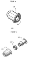
- Figure 1 illustrates a fitting 100 according to the prior art "Elaflex" filling system.
- the fitting 100 is assembled for use, while Figure 1b provides an exploded view, drawing attention to the different parts comprised in the fitting.
- the "Elaflex" fitting 100 is equipped with a ring magnet 102, the magnetic field of which acts on a magnetically actuated switch present in an "Elaflex" compatible spout. Only when an appropriate magnetic field is applied to this switch, a flow of urea solution through the spout is authorized. This prevents filling up a tank intended for a different fluid with a urea solution, because other tanks would not be equipped with a magnet.
- the circular symmetry of the magnetic field provided by the ring magnet 102 ensures proper operation regardless of the angular positioning of the fitting in the fluid tank, and regardless of the angular positioning of the spout in the fitting.
- a further preventive measure against inadvertent filling of the urea tank with a different fluid is provided by the diameter of the inner tube 103 of the fitting 100.
- the diameter of this inner tube 103 is less than the diameter of a standardized spout for dispensing gasoline or diesel fuel. Hence, it is mechanically impossible to enter such a fuel spout in the fitting 100 of a urea tank.
- the "Elaflex" spout will shut off when it detects that the level of liquid in the tank has reached the spout. More specifically, the spout will shut off when the spout opening is no longer in contact with air, i.e. no longer ventilated. This implies a need for proper ventilation of the space in which the spout opening is placed, in order for the spout to function properly up to the point where the tank is full.
- the air and/or vapor present in the tank needs to be able to escape from the tank at the rate at which the urea solution is fed into it. If the spout is not equipped with an internal vapor recovery system, these gases will typically escape through the part of the inner tube 103 that is not obstructed by the spout. It is therefore important that the air and/or vapor be allowed to efficiently reach the opening at the tank side of the fitting.
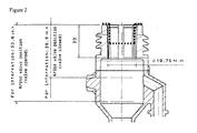
- Figure 2 illustrates an embodiment of a fitting according to the "Kruse" system.
- FIG. 3 illustrates an embodiment of the fitting according to the present invention.
- the fitting 300 comprises a tubular main body 301 having a first end 302 for connection with said tank and a second end 303 adapted to receive a spout.
- the tubular main body 301 has a funnel shaped section 308 at the first end 302.
- the fitting may produced from polyamide, polyethylene, or other materials with suitable properties. It may be permanently attached to the filling opening of a fluid tank by means of welding or any other suitable attachment process. Alternatively, the first end may be formed as a hose tail for attaching a flexible hose leading to the fluid tank.
- the main body 301 is adapted to be equipped with a magnet 304 substantially spanning the circumference of the main body 301 for authorizing a flow in the spout.
- the fitting further comprises a tubular coupling section 305 at said second end 303.
- the tubular coupling section 305 is adapted to detachably couple to a bottle such that a protruding part of this bottle substantially seals the fitting both near the tubular coupling section 305 and near the magnet 304, thus creating a closed chamber 307 between the tubular coupling section 305 and the magnet 304.
- the tubular coupling section 305 is optionally provided in the form of a threaded protrusion extending beyond a plane or a flange at the second end 303.
- a first ventilation conduit 306 is embedded in a ridge passing through a constricted zone 311 holding the magnet 304.
- the main body 301 is also ventilated at the tank side, outside the chamber 307.
- a second ventilation conduit 309 is provided for this purpose.
- the second ventilation conduit 309 is in fluid communication with a volume of gas present at the tank side of the fitting.
- the first ventilation conduit 306 is in fluid communication with that volume of gas via the second ventilation conduit 309.
- the first ventilation circuit provides direct fluid communication between the chamber 307 and the volume of gas at the tank side, the first ventilation conduit passing on the outside of the main body 301, and in which the second ventilation conduit is embedded in a ridge passing through the constricted zone 311 holding the magnet 304.
- the second ventilation conduit 306 is in fluid communication with the volume of gas at the tank side via the second ventilation circuit 309.
- first ventilation conduit 306 and the second ventilation conduit 309 are bifurcations of a single ventilation conduit 310 in fluid communication with a volume of gas present at the tank side of the fitting 300.
- the fitting comprises a first ventilation conduit 306 ending in the chamber 307, the first ventilation conduit 306 being in fluid communication with a volume of gas present at the tank side of the fitting.
- the main body 301 is also ventilated at the tank side, outside the chamber 307, by means of separate second ventilation conduit 309.
- the second ventilation conduit 309 is also in fluid communication with a volume of gas present at the tank side of the fitting.
- the first ventilation conduit 306 is formed by a central cavity of the tubular main body 301, the central cavity receiving a part of the bottle 312 in the coupled position, wherein the central cavity is dimensioned with a radius that exceeds a radius of the received part of the bottle 312 in an amount sufficient to provide fluid communication between the chamber 307 and the tank side of the fitting.
- the first ventilation conduit 306 provides direct fluid communication between the chamber 307 and the volume of gas at the tank side, the first ventilation conduit passing on the outside of the main body 301, and in which the second ventilation conduit is formed by a central cavity of the tubular main body 301, the central cavity receiving a part of the bottle 312 in the coupled position, wherein the central cavity is dimensioned with a radius that exceeds a radius of the received part of the bottle 312 in an amount sufficient to provide fluid communication between the chamber 307 and the tank side of the main body.
- the second ventilation conduit 306 is in fluid communication with the volume of gas at the tank side via the second ventilation conduit 309.
- Figure 7 provides a perspective view of a magnet in the shape of an interrupted ring, as may be used in the embodiment illustrated in Figure 3 .
- the sector over which the ring is interrupted preferably measures between 20° and 40°.
- Figure 8 provides a perspective view of a magnet in the shape of a ring with two interruptions, i.e., a magnet consisting of three separate sector-shaped elements.
- the concept of a substantially annular magnet or a magnet consisting of an interrupted ring, as used in the present application, must be understood to also refer to combinations of multiple parts, substantially extending along a ring, as illustrated in an exemplary way in Figure 8 .
Landscapes
- Engineering & Computer Science (AREA)
- Transportation (AREA)
- Sustainable Development (AREA)
- Sustainable Energy (AREA)
- Chemical & Material Sciences (AREA)
- Combustion & Propulsion (AREA)
- Life Sciences & Earth Sciences (AREA)
- Mechanical Engineering (AREA)
- Filling Or Discharging Of Gas Storage Vessels (AREA)
- Cooling, Air Intake And Gas Exhaust, And Fuel Tank Arrangements In Propulsion Units (AREA)
- Filling Of Jars Or Cans And Processes For Cleaning And Sealing Jars (AREA)
- Quick-Acting Or Multi-Walled Pipe Joints (AREA)
- Exhaust Gas After Treatment (AREA)
- Loading And Unloading Of Fuel Tanks Or Ships (AREA)
Claims (13)
- Armatur (300) für die Füllöffnung eines Fluidtanks, umfassend einen rohrförmigen Hauptkörper (301) mit einem ersten Ende (302) zur Verbindung mit dem Tank und einem zweiten Ende (303), das dazu angepasst ist, einen Stutzen aufzunehmen, wobei der Hauptkörper dazu angepasst ist, mit einem Magneten (304) ausgestattet zu sein, der im Wesentlichen den Umfang des Hauptkörpers überspannt, um eine Strömung im Stutzen zuzulassen, und einem rohrförmigen Kupplungsabschnitt (305) am zweiten Ende, dadurch gekennzeichnet, dass der rohrförmige Kupplungsabschnitt (305) zum lösbaren Anschluss an eine über einen Fluidauslass und einen Lufteinlass verfügende Flasche (312) angepasst ist, dass die Armatur eine Kammer (307) zwischen dem zweiten Ende und dem Magneten umfasst, dass im Gebrauch ein Ende einer ersten Lüftungsleitung (306) in der Kammer (307) vorhanden ist, wobei die erste Lüftungsleitung (306) mit einem auf der Tankseite der Armatur vorhandenen Gasvolumen in Fluidverbindung steht, derart, dass sich in der angeschlossenen Position der Flasche (312) der Lufteinlass in der Kammer (307) befindet und der Fluidauslass in der Richtung des ersten Endes mündet, und dass im Gebrauch ein Ende einer zweiten Lüftungsleitung (309) im rohrförmigen Hauptkörper (301) auf der Tankseite des Magneten (304) vorhanden ist, wobei die zweite Lüftungsleitung (309) mit dem auf der Tankseite der Armatur vorhandenen Gasvolumen in Fluidverbindung steht.
- Armatur nach Anspruch 1, wobei es sich bei der Flasche um eine Aufschraubflasche handelt, dadurch gekennzeichnet, dass der rohrförmige Kupplungsabschnitt (305) ein Gewinde zum lösbaren Anschluss an die Flasche (312) besitzt.
- Armatur nach Anspruch 2, dadurch gekennzeichnet, dass der rohrförmige Kupplungsabschnitt (305) dazu angepasst ist, mit einer Kruse-Flasche so verbunden zu werden, dass der Fluidauslass im Wesentlichen die Kammer ab dem ersten Ende in der angeschlossenen Position der Kruse-Flasche dicht verschließt.
- Armatur nach einem der Ansprüche 1 bis 3, darüber hinaus dadurch gekennzeichnet, dass der rohrförmige Hauptkörper (301) eine Umfangsnut zum Halten des Magnets (304) umfasst, und dass sich die erste Lüftungsleitung (306) oder die zweite Lüftungsleitung (309) im Wesentlichen axial durch die Nut erstreckt.
- Armatur nach Anspruch 4, darüber hinaus dadurch gekennzeichnet, dass die erste Lüftungsleitung (306) oder die zweite Lüftungsleitung (309) in eine axiale Erhöhung eingebettet ist, welche die radiale Nut kreuzt.
- Armatur nach Anspruch 4 oder Anspruch 5, darüber hinaus dadurch gekennzeichnet, dass sie einen Magneten (304) umfasst, der aus einem unterbrochenen Ring besteht, der sich in der Umfangsnut befindet, wobei die Unterbrechung dazu angepasst ist, die erste Lüftungsleitung oder die zweite Lüftungsleitung zu flankieren.
- Armatur nach Anspruch 6, darüber hinaus dadurch gekennzeichnet, dass sich der unterbrochene Ring über einen zwischen 20° und 40° betragenden Sektor erstreckt.
- Armatur nach Anspruch 1 oder Anspruch 2, darüber hinaus dadurch gekennzeichnet, dass die erste Lüftungsleitung (306) oder die zweite Lüftungsleitung (309) mittels eines zentralen Hohlraums des rohrförmigen Hauptkörpers (301) gebildet ist, wobei der zentrale Hohlraum in der angeschlossenen Position einen Teil der Flasche (312) aufnimmt, wobei der zentrale Hohlraum mit einem Radius dimensioniert ist, der einen Radius des aufgenommenen Teils der Flasche um einen Betrag übersteigt, der ausreicht, um eine Fluidverbindung zwischen der Kammer und der Tankseite des Hauptkörpers bereitzustellen.
- Armatur nach Anspruch 1 oder Anspruch 2, darüber hinaus dadurch gekennzeichnet, dass es sich bei der ersten und zweiten Lüftungsleitung (306, 309) um Verzweigungen einer einzelnen Leitung (310) handelt, die in Fluidverbindung mit dem auf der Tankseite der Armatur vorhandenen Gasvolumen steht.
- Armatur nach jedem der vorhergehenden Ansprüche, darüber hinaus dadurch gekennzeichnet, dass sie einen trichterförmigen Abschnitt am ersten Ende (302) umfasst.
- Armatur nach jedem der vorhergehenden Ansprüche, darüber hinaus dadurch gekennzeichnet, dass sie einen Verbindungsflansch nahe dem zweiten Ende umfasst, und der rohrförmige Kupplungsabschnitt (305) über den Flansch hinaus vorsteht.
- Armatur nach jedem der vorhergehenden Ansprüche, darüber hinaus dadurch gekennzeichnet, dass sie einen verengten Bereich (311) mit einem reduzierten Innendurchmesser umfasst, der im Wesentlichen gleich dem Durchmesser des Stutzens und dem Auslass der Flasche (312) ist.
- Fahrzeugfluidtank, dadurch gekennzeichnet, dass er eine Armatur (300) nach jedem der vorhergehenden Ansprüche umfasst.
Applications Claiming Priority (2)
| Application Number | Priority Date | Filing Date | Title |
|---|---|---|---|
| EP09173578A EP2316685A1 (de) | 2009-10-21 | 2009-10-21 | Verbessertes Füllsystem für Fahrzeugflüssigkeitsbehälter |
| PCT/EP2010/065477 WO2011048016A1 (en) | 2009-10-21 | 2010-10-14 | Improved filling system for vehicular fluid container |
Publications (3)
| Publication Number | Publication Date |
|---|---|
| EP2490914A1 EP2490914A1 (de) | 2012-08-29 |
| EP2490914B1 true EP2490914B1 (de) | 2013-08-07 |
| EP2490914B2 EP2490914B2 (de) | 2022-02-09 |
Family
ID=41728345
Family Applications (2)
| Application Number | Title | Priority Date | Filing Date |
|---|---|---|---|
| EP09173578A Withdrawn EP2316685A1 (de) | 2009-10-21 | 2009-10-21 | Verbessertes Füllsystem für Fahrzeugflüssigkeitsbehälter |
| EP10765447.7A Active EP2490914B2 (de) | 2009-10-21 | 2010-10-14 | Verbessertes füllsystem für fahrzeugflüssigkeitsbehälter |
Family Applications Before (1)
| Application Number | Title | Priority Date | Filing Date |
|---|---|---|---|
| EP09173578A Withdrawn EP2316685A1 (de) | 2009-10-21 | 2009-10-21 | Verbessertes Füllsystem für Fahrzeugflüssigkeitsbehälter |
Country Status (8)
| Country | Link |
|---|---|
| US (2) | US8919393B2 (de) |
| EP (2) | EP2316685A1 (de) |
| JP (1) | JP5766195B2 (de) |
| KR (2) | KR20170042814A (de) |
| CN (1) | CN102596622B (de) |
| BR (1) | BR112012009286A2 (de) |
| RU (1) | RU2539615C2 (de) |
| WO (1) | WO2011048016A1 (de) |
Families Citing this family (17)
| Publication number | Priority date | Publication date | Assignee | Title |
|---|---|---|---|---|
| EP2316685A1 (de) * | 2009-10-21 | 2011-05-04 | Inergy Automotive Systems Research (Société Anonyme) | Verbessertes Füllsystem für Fahrzeugflüssigkeitsbehälter |
| DE202011105302U1 (de) * | 2011-09-05 | 2012-12-10 | Reutter Gmbh | Einfüllstutzen für einen Flüssigkeitsvorratsbehälter eines Kraftfahrzeugs mit einem integrierten Entlüftungskanal |
| DE102011115144A1 (de) * | 2011-09-27 | 2013-03-28 | Veritas Ag | Einfüllvorrichtung |
| DE202012004118U1 (de) * | 2011-12-21 | 2012-07-16 | Reutter Gmbh | Einrichtung zum Verhindern einer Fehlbefüllung eines Behälters von beispielsweise Kraftfahrzeugen mittels eines Zapfventils |
| DE202011109524U1 (de) * | 2011-12-21 | 2013-03-25 | Reutter Gmbh | Füllrohranordnung für einen Flüssigkeitsvorratsbehälter fürKraftfahrzeuge |
| CN102530564A (zh) * | 2012-01-11 | 2012-07-04 | 北京交通大学 | 一种可防堵塞的悬浮式物料传输系统陶瓷喷嘴 |
| DE102012012651A1 (de) * | 2012-06-25 | 2014-01-02 | GM Global Technology Operations LLC (n. d. Ges. d. Staates Delaware) | Einfülladapter zum Befüllen eines Tanks fürPersonenkraftwagen an einer Zapfsäule für Lastkraftwagen |
| WO2014039816A2 (en) * | 2012-09-06 | 2014-03-13 | Kemkey, Llc | Material transfer system and method of transferring material |
| US9701531B2 (en) * | 2015-04-10 | 2017-07-11 | Veritas Ag | Filling head for a liquid tank |
| EP3088231A1 (de) | 2015-04-28 | 2016-11-02 | Inergy Automotive Systems Research (Société Anonyme) | Ammoniakvorläufer-nachfüllvorrichtung |
| DE102016102737A1 (de) * | 2015-09-22 | 2017-03-23 | Dr. Ing. H.C. F. Porsche Aktiengesellschaft | Einfüllstutzen |
| CN108602253B (zh) * | 2016-05-12 | 2020-10-16 | 惠普发展公司有限责任合伙企业 | 出口结构 |
| FR3051736B1 (fr) * | 2016-05-27 | 2020-09-04 | Coutier Moulage Gen Ind | Tete de remplissage pour le remplissage d’un reservoir par un liquide |
| US10207913B2 (en) * | 2016-06-09 | 2019-02-19 | Hyundai Motor Company | Fuel-urea injection apparatus including common inlet for vehicle |
| JP6852633B2 (ja) * | 2017-09-26 | 2021-03-31 | 豊田合成株式会社 | 燃料タンク用逆止弁 |
| US10737928B2 (en) | 2018-02-23 | 2020-08-11 | Husky Corporation | Nozzle for delivery of auxiliary or additive fluid for treating exhaust for a diesel motor for autos or truck vehicle or the like |
| US11371409B2 (en) * | 2019-05-21 | 2022-06-28 | Paccar Inc | Fluid containers and components thereof |
Family Cites Families (49)
| Publication number | Priority date | Publication date | Assignee | Title |
|---|---|---|---|---|
| US3187936A (en) | 1962-11-01 | 1965-06-08 | Gen Motors Corp | Integral fuel filler pipe and vent tube |
| DE2438957A1 (de) * | 1974-08-14 | 1976-03-04 | Danfoss As | Magnetventil fuer duesenbrenner |
| JPS5367912U (de) * | 1976-10-28 | 1978-06-07 | ||
| IT206208Z2 (it) | 1985-11-15 | 1987-07-13 | Italiana Serrature Torino | Organo di adduzione carburante per veicoli |
| JPS6448326U (de) * | 1987-09-21 | 1989-03-24 | ||
| DE4028571C1 (en) * | 1990-09-08 | 1992-02-06 | Karlheinz 2000 Hamburg De Ehlers | Gas return on vehicle fuel tank filler - has choke acting as flow metering device and gas return line encloses liq. fuel line |
| JPH04317821A (ja) | 1991-04-18 | 1992-11-09 | Toyoda Gosei Co Ltd | 車両用燃料タンク |
| JPH05162546A (ja) | 1991-12-13 | 1993-06-29 | Toyoda Gosei Co Ltd | 車両用燃料タンク |
| JP2715702B2 (ja) | 1991-07-02 | 1998-02-18 | 日産自動車株式会社 | 燃料タンクのバルブ配置構造 |
| JP2529293Y2 (ja) | 1991-10-04 | 1997-03-19 | 本田技研工業株式会社 | 燃料タンクにおける給油時の蒸発燃料大気放出抑制装置 |
| JP2556930Y2 (ja) | 1991-11-26 | 1997-12-08 | エヌオーケー株式会社 | 給油管の切替弁装置 |
| US5538055A (en) * | 1992-12-16 | 1996-07-23 | Temetec Fahrzeugtechnik Entwicklungsgesellschaft Mbh | Tank closure |
| KR960006580Y1 (ko) | 1993-04-22 | 1996-08-03 | 노갑부 | 환자용 소변 집료장치 |
| DE4344273C2 (de) | 1993-12-23 | 1995-12-14 | Bayerische Motoren Werke Ag | Einfüllstutzen für einen Kraftstoffbehälter eines Kraftfahrzeuges |
| JPH07237459A (ja) | 1994-03-01 | 1995-09-12 | Om Kogyo Kk | 燃料タンクの通気開閉装置 |
| JPH07257201A (ja) | 1994-03-24 | 1995-10-09 | Nissan Motor Co Ltd | 燃料タンクの注油口構造 |
| US5476125A (en) * | 1994-06-24 | 1995-12-19 | Husky Corporation | Vapor recovery gasoline dispensing nozzle |
| US5562133A (en) | 1994-06-24 | 1996-10-08 | Hiesky Corporation | Fuel dispensing nozzle |
| JP2937065B2 (ja) | 1995-03-27 | 1999-08-23 | 三菱自動車工業株式会社 | 燃料貯蔵装置 |
| US6263924B1 (en) | 1998-11-23 | 2001-07-24 | Mobil Oil Corporation | Vehicle engine system additive dispenser |
| JP2000203278A (ja) * | 1999-01-11 | 2000-07-25 | Futaba Industrial Co Ltd | フュ―エルインレット |
| US6390147B1 (en) * | 2001-05-17 | 2002-05-21 | Ford Global Technologies, Inc. | Fuel and reductant delivery system |
| US6554031B2 (en) * | 2001-05-17 | 2003-04-29 | Ford Global Technologies, Inc. | Two fluid dispensing apparatus to supply fuel and reductant to a vehicle |
| DE10241323B9 (de) * | 2002-09-04 | 2004-12-16 | Matthias Hoffmann | Vorrichtung zur Verhinderung falscher Betankung von Kraftfahrzeugen |
| FR2846713B1 (fr) | 2002-11-04 | 2006-03-10 | Marwal Systems | Dispositif de dosage d'additif pour carburant sur vehicule automobile |
| DE502004008441D1 (de) | 2003-08-01 | 2008-12-24 | Jost Automotive Gmbh | Vorrichtung zum Vermeiden einer Fehlbetankung bei Kraftfahrzeugen |
| DE20319414U1 (de) * | 2003-12-15 | 2005-03-24 | Merlaku Kastriot | Schutz-System gegen Betanken eines Fahrzeugs mit falschen Kraftstoff |
| DE102004036508A1 (de) * | 2004-07-28 | 2006-03-23 | Daimlerchrysler Ag | Tankbehälter |
| FR2875748B1 (fr) | 2004-09-27 | 2006-12-08 | Inergy Automotive Systems Res | Methode de remplissage d'un reservoir au moyen d'une cartouche-reservoir et cartouche associes |
| FR2879585B1 (fr) | 2004-12-16 | 2010-06-11 | Inergy Automotive Systems Res | Cartouche de reserve pour reservoir |
| DE202005011575U1 (de) * | 2005-07-13 | 2006-11-23 | Reutter Metallwarenfabrik Gmbh | Einfüllstutzen für einen Behälter |
| DE202006009585U1 (de) | 2006-01-24 | 2006-09-28 | Kämpf, Ralf | Verbindungsbaugruppe zur Verbindung eines Ausgangsbehälters und eines Zielbehälters |
| US8028729B2 (en) | 2006-01-24 | 2011-10-04 | Ralf Kaempf | Connecting subassembly for connecting an initial container and a target container |
| JP4884156B2 (ja) | 2006-10-12 | 2012-02-29 | トヨタ自動車株式会社 | 燃料タンクの給油口構造 |
| JP4810391B2 (ja) | 2006-10-12 | 2011-11-09 | トヨタ自動車株式会社 | 外気取入部構造 |
| JP2008138721A (ja) * | 2006-11-30 | 2008-06-19 | Kurashiki Kako Co Ltd | 気体圧サーボバルブ |
| CN201031996Y (zh) * | 2007-03-30 | 2008-03-05 | 邓玉斌 | 太阳能热水器管道排空阀 |
| EP2181010A1 (de) | 2007-07-23 | 2010-05-05 | Renault Trucks | Anordnung eines einfüllstutzens für einen fahrzeugtank |
| RU2363597C1 (ru) * | 2007-10-31 | 2009-08-10 | Институт физики им. Л.В. Киренского Сибирского отделения РАН | Крышка заливной горловины топливного бака транспортного средства (варианты) |
| DE202007018245U1 (de) * | 2007-12-21 | 2009-04-30 | Reutter Gmbh | Adapter für einen Einfüllstutzen eines Harnstoffbehälters |
| DE102008010988B3 (de) | 2008-02-25 | 2009-07-16 | Elaflex Tankstellentechnik Gmbh & Co | Zapfpistole |
| DE102008049150A1 (de) | 2008-06-09 | 2009-12-10 | Kt Projektentwicklungs-Gmbh | Einsatzelement für einen zur tankstellenseitigen Befüllung mit Harnstoff geeigneten Behälter |
| DE102008047523B3 (de) * | 2008-09-16 | 2010-04-29 | Elaflex-Gummi Ehlers Gmbh | Zapfventil mit Einrichtung zur Absaugung von Kraftstoffdämpfen |
| CN201301978Y (zh) * | 2008-12-02 | 2009-09-02 | 十堰市正发汽车零部件有限公司 | 一种汽车用新型二位三通常通气路电磁控制阀 |
| DE102009011518A1 (de) | 2009-03-06 | 2010-09-16 | Kautex Textron Gmbh & Co. Kg | Reduktionsmittelbehälter |
| DE102009029362A1 (de) | 2009-09-11 | 2011-03-24 | Erhard & Söhne GmbH | Behaelter zur Aufnahme eines Kraft- und/oder Betriebsstoffes fuer Fahrzeuge |
| EP2316685A1 (de) * | 2009-10-21 | 2011-05-04 | Inergy Automotive Systems Research (Société Anonyme) | Verbessertes Füllsystem für Fahrzeugflüssigkeitsbehälter |
| DE202010016319U1 (de) * | 2010-12-04 | 2012-03-19 | Reutter Gmbh | Einsatz für einen Einfüllstutzen eines Harnstoffbehälters |
| DE102011115144A1 (de) * | 2011-09-27 | 2013-03-28 | Veritas Ag | Einfüllvorrichtung |
-
2009
- 2009-10-21 EP EP09173578A patent/EP2316685A1/de not_active Withdrawn
-
2010
- 2010-10-14 WO PCT/EP2010/065477 patent/WO2011048016A1/en not_active Ceased
- 2010-10-14 RU RU2012120755/11A patent/RU2539615C2/ru not_active IP Right Cessation
- 2010-10-14 CN CN201080048958.8A patent/CN102596622B/zh active Active
- 2010-10-14 EP EP10765447.7A patent/EP2490914B2/de active Active
- 2010-10-14 US US13/502,444 patent/US8919393B2/en active Active
- 2010-10-14 JP JP2012534637A patent/JP5766195B2/ja not_active Expired - Fee Related
- 2010-10-14 KR KR1020177009538A patent/KR20170042814A/ko not_active Ceased
- 2010-10-14 KR KR1020127010549A patent/KR101727346B1/ko not_active Expired - Fee Related
- 2010-10-14 BR BR112012009286A patent/BR112012009286A2/pt not_active IP Right Cessation
-
2014
- 2014-11-19 US US14/548,099 patent/US10576819B2/en active Active
Also Published As
| Publication number | Publication date |
|---|---|
| EP2490914B2 (de) | 2022-02-09 |
| CN102596622B (zh) | 2015-05-06 |
| US20150076147A1 (en) | 2015-03-19 |
| CN102596622A (zh) | 2012-07-18 |
| KR101727346B1 (ko) | 2017-04-14 |
| WO2011048016A1 (en) | 2011-04-28 |
| BR112012009286A2 (pt) | 2016-05-31 |
| US10576819B2 (en) | 2020-03-03 |
| EP2316685A1 (de) | 2011-05-04 |
| JP5766195B2 (ja) | 2015-08-19 |
| RU2012120755A (ru) | 2013-11-27 |
| US8919393B2 (en) | 2014-12-30 |
| KR20170042814A (ko) | 2017-04-19 |
| US20120199246A1 (en) | 2012-08-09 |
| KR20120089689A (ko) | 2012-08-13 |
| RU2539615C2 (ru) | 2015-01-20 |
| EP2490914A1 (de) | 2012-08-29 |
| JP2013508229A (ja) | 2013-03-07 |
Similar Documents
| Publication | Publication Date | Title |
|---|---|---|
| EP2490914B2 (de) | Verbessertes füllsystem für fahrzeugflüssigkeitsbehälter | |
| US8800611B2 (en) | Insert element for a container suitable for filling with urea at a filling station | |
| US6390147B1 (en) | Fuel and reductant delivery system | |
| EP2928717B1 (de) | Einfüllstutzenanordnung und herstellungsverfahren dafür | |
| US9206028B2 (en) | Dispense head | |
| US20090188923A1 (en) | Urea solution tank assembly | |
| US10640358B2 (en) | Capless refill adapter for a fluid refilling system | |
| US10190458B2 (en) | Storage tank for aqueous urea solution in a motor vehicle | |
| US20090321441A1 (en) | Filler tube for a tank | |
| US9272618B2 (en) | Misfuelling prevention device for a filler neck of a fuel tank | |
| US20130001226A1 (en) | Filler neck for a fuel tank | |
| US11072470B2 (en) | Diesel exhaust fluid tank with integrated mis-filling prevention device | |
| US6938612B2 (en) | Auxiliary fuel dispensing system | |
| US11420864B2 (en) | Filling heads | |
| CN101410322A (zh) | 用于连接一个输出容器与一个目标容器的连接组件 | |
| AU2008274386B2 (en) | Dispense head |
Legal Events
| Date | Code | Title | Description |
|---|---|---|---|
| PUAI | Public reference made under article 153(3) epc to a published international application that has entered the european phase |
Free format text: ORIGINAL CODE: 0009012 |
|
| 17P | Request for examination filed |
Effective date: 20120521 |
|
| AK | Designated contracting states |
Kind code of ref document: A1 Designated state(s): AL AT BE BG CH CY CZ DE DK EE ES FI FR GB GR HR HU IE IS IT LI LT LU LV MC MK MT NL NO PL PT RO RS SE SI SK SM TR |
|
| DAX | Request for extension of the european patent (deleted) | ||
| GRAP | Despatch of communication of intention to grant a patent |
Free format text: ORIGINAL CODE: EPIDOSNIGR1 |
|
| GRAS | Grant fee paid |
Free format text: ORIGINAL CODE: EPIDOSNIGR3 |
|
| GRAA | (expected) grant |
Free format text: ORIGINAL CODE: 0009210 |
|
| AK | Designated contracting states |
Kind code of ref document: B1 Designated state(s): AL AT BE BG CH CY CZ DE DK EE ES FI FR GB GR HR HU IE IS IT LI LT LU LV MC MK MT NL NO PL PT RO RS SE SI SK SM TR |
|
| REG | Reference to a national code |
Ref country code: GB Ref legal event code: FG4D |
|
| REG | Reference to a national code |
Ref country code: AT Ref legal event code: REF Ref document number: 625594 Country of ref document: AT Kind code of ref document: T Effective date: 20130815 Ref country code: CH Ref legal event code: EP |
|
| REG | Reference to a national code |
Ref country code: IE Ref legal event code: FG4D |
|
| REG | Reference to a national code |
Ref country code: DE Ref legal event code: R096 Ref document number: 602010009254 Country of ref document: DE Effective date: 20131002 |
|
| REG | Reference to a national code |
Ref country code: AT Ref legal event code: MK05 Ref document number: 625594 Country of ref document: AT Kind code of ref document: T Effective date: 20130807 |
|
| REG | Reference to a national code |
Ref country code: NL Ref legal event code: VDEP Effective date: 20130807 |
|
| REG | Reference to a national code |
Ref country code: LT Ref legal event code: MG4D |
|
| PG25 | Lapsed in a contracting state [announced via postgrant information from national office to epo] |
Ref country code: LT Free format text: LAPSE BECAUSE OF FAILURE TO SUBMIT A TRANSLATION OF THE DESCRIPTION OR TO PAY THE FEE WITHIN THE PRESCRIBED TIME-LIMIT Effective date: 20130807 Ref country code: PT Free format text: LAPSE BECAUSE OF FAILURE TO SUBMIT A TRANSLATION OF THE DESCRIPTION OR TO PAY THE FEE WITHIN THE PRESCRIBED TIME-LIMIT Effective date: 20131209 Ref country code: CY Free format text: LAPSE BECAUSE OF FAILURE TO SUBMIT A TRANSLATION OF THE DESCRIPTION OR TO PAY THE FEE WITHIN THE PRESCRIBED TIME-LIMIT Effective date: 20130911 Ref country code: SE Free format text: LAPSE BECAUSE OF FAILURE TO SUBMIT A TRANSLATION OF THE DESCRIPTION OR TO PAY THE FEE WITHIN THE PRESCRIBED TIME-LIMIT Effective date: 20130807 Ref country code: AT Free format text: LAPSE BECAUSE OF FAILURE TO SUBMIT A TRANSLATION OF THE DESCRIPTION OR TO PAY THE FEE WITHIN THE PRESCRIBED TIME-LIMIT Effective date: 20130807 Ref country code: HR Free format text: LAPSE BECAUSE OF FAILURE TO SUBMIT A TRANSLATION OF THE DESCRIPTION OR TO PAY THE FEE WITHIN THE PRESCRIBED TIME-LIMIT Effective date: 20130807 Ref country code: IS Free format text: LAPSE BECAUSE OF FAILURE TO SUBMIT A TRANSLATION OF THE DESCRIPTION OR TO PAY THE FEE WITHIN THE PRESCRIBED TIME-LIMIT Effective date: 20131207 Ref country code: NO Free format text: LAPSE BECAUSE OF FAILURE TO SUBMIT A TRANSLATION OF THE DESCRIPTION OR TO PAY THE FEE WITHIN THE PRESCRIBED TIME-LIMIT Effective date: 20131107 |
|
| PG25 | Lapsed in a contracting state [announced via postgrant information from national office to epo] |
Ref country code: PL Free format text: LAPSE BECAUSE OF FAILURE TO SUBMIT A TRANSLATION OF THE DESCRIPTION OR TO PAY THE FEE WITHIN THE PRESCRIBED TIME-LIMIT Effective date: 20130807 Ref country code: BE Free format text: LAPSE BECAUSE OF FAILURE TO SUBMIT A TRANSLATION OF THE DESCRIPTION OR TO PAY THE FEE WITHIN THE PRESCRIBED TIME-LIMIT Effective date: 20130807 Ref country code: SI Free format text: LAPSE BECAUSE OF FAILURE TO SUBMIT A TRANSLATION OF THE DESCRIPTION OR TO PAY THE FEE WITHIN THE PRESCRIBED TIME-LIMIT Effective date: 20130807 Ref country code: NL Free format text: LAPSE BECAUSE OF FAILURE TO SUBMIT A TRANSLATION OF THE DESCRIPTION OR TO PAY THE FEE WITHIN THE PRESCRIBED TIME-LIMIT Effective date: 20130807 Ref country code: FI Free format text: LAPSE BECAUSE OF FAILURE TO SUBMIT A TRANSLATION OF THE DESCRIPTION OR TO PAY THE FEE WITHIN THE PRESCRIBED TIME-LIMIT Effective date: 20130807 Ref country code: LV Free format text: LAPSE BECAUSE OF FAILURE TO SUBMIT A TRANSLATION OF THE DESCRIPTION OR TO PAY THE FEE WITHIN THE PRESCRIBED TIME-LIMIT Effective date: 20130807 Ref country code: GR Free format text: LAPSE BECAUSE OF FAILURE TO SUBMIT A TRANSLATION OF THE DESCRIPTION OR TO PAY THE FEE WITHIN THE PRESCRIBED TIME-LIMIT Effective date: 20131108 |
|
| PG25 | Lapsed in a contracting state [announced via postgrant information from national office to epo] |
Ref country code: CY Free format text: LAPSE BECAUSE OF FAILURE TO SUBMIT A TRANSLATION OF THE DESCRIPTION OR TO PAY THE FEE WITHIN THE PRESCRIBED TIME-LIMIT Effective date: 20130807 |
|
| PG25 | Lapsed in a contracting state [announced via postgrant information from national office to epo] |
Ref country code: EE Free format text: LAPSE BECAUSE OF FAILURE TO SUBMIT A TRANSLATION OF THE DESCRIPTION OR TO PAY THE FEE WITHIN THE PRESCRIBED TIME-LIMIT Effective date: 20130807 Ref country code: CZ Free format text: LAPSE BECAUSE OF FAILURE TO SUBMIT A TRANSLATION OF THE DESCRIPTION OR TO PAY THE FEE WITHIN THE PRESCRIBED TIME-LIMIT Effective date: 20130807 Ref country code: DK Free format text: LAPSE BECAUSE OF FAILURE TO SUBMIT A TRANSLATION OF THE DESCRIPTION OR TO PAY THE FEE WITHIN THE PRESCRIBED TIME-LIMIT Effective date: 20130807 Ref country code: RO Free format text: LAPSE BECAUSE OF FAILURE TO SUBMIT A TRANSLATION OF THE DESCRIPTION OR TO PAY THE FEE WITHIN THE PRESCRIBED TIME-LIMIT Effective date: 20130807 Ref country code: SK Free format text: LAPSE BECAUSE OF FAILURE TO SUBMIT A TRANSLATION OF THE DESCRIPTION OR TO PAY THE FEE WITHIN THE PRESCRIBED TIME-LIMIT Effective date: 20130807 |
|
| PLBI | Opposition filed |
Free format text: ORIGINAL CODE: 0009260 |
|
| PG25 | Lapsed in a contracting state [announced via postgrant information from national office to epo] |
Ref country code: MC Free format text: LAPSE BECAUSE OF FAILURE TO SUBMIT A TRANSLATION OF THE DESCRIPTION OR TO PAY THE FEE WITHIN THE PRESCRIBED TIME-LIMIT Effective date: 20130807 Ref country code: IT Free format text: LAPSE BECAUSE OF FAILURE TO SUBMIT A TRANSLATION OF THE DESCRIPTION OR TO PAY THE FEE WITHIN THE PRESCRIBED TIME-LIMIT Effective date: 20130807 Ref country code: ES Free format text: LAPSE BECAUSE OF FAILURE TO SUBMIT A TRANSLATION OF THE DESCRIPTION OR TO PAY THE FEE WITHIN THE PRESCRIBED TIME-LIMIT Effective date: 20130807 |
|
| 26 | Opposition filed |
Opponent name: KAUTEX TEXTRON GMBH & CO. KG Effective date: 20140425 |
|
| PLAX | Notice of opposition and request to file observation + time limit sent |
Free format text: ORIGINAL CODE: EPIDOSNOBS2 |
|
| REG | Reference to a national code |
Ref country code: DE Ref legal event code: R026 Ref document number: 602010009254 Country of ref document: DE Effective date: 20140425 |
|
| REG | Reference to a national code |
Ref country code: IE Ref legal event code: MM4A |
|
| PLAF | Information modified related to communication of a notice of opposition and request to file observations + time limit |
Free format text: ORIGINAL CODE: EPIDOSCOBS2 |
|
| PG25 | Lapsed in a contracting state [announced via postgrant information from national office to epo] |
Ref country code: IE Free format text: LAPSE BECAUSE OF NON-PAYMENT OF DUE FEES Effective date: 20131014 |
|
| PLBB | Reply of patent proprietor to notice(s) of opposition received |
Free format text: ORIGINAL CODE: EPIDOSNOBS3 |
|
| PG25 | Lapsed in a contracting state [announced via postgrant information from national office to epo] |
Ref country code: SM Free format text: LAPSE BECAUSE OF FAILURE TO SUBMIT A TRANSLATION OF THE DESCRIPTION OR TO PAY THE FEE WITHIN THE PRESCRIBED TIME-LIMIT Effective date: 20130807 |
|
| REG | Reference to a national code |
Ref country code: CH Ref legal event code: PL |
|
| GBPC | Gb: european patent ceased through non-payment of renewal fee |
Effective date: 20141014 |
|
| PG25 | Lapsed in a contracting state [announced via postgrant information from national office to epo] |
Ref country code: CH Free format text: LAPSE BECAUSE OF NON-PAYMENT OF DUE FEES Effective date: 20141031 Ref country code: LI Free format text: LAPSE BECAUSE OF NON-PAYMENT OF DUE FEES Effective date: 20141031 Ref country code: BG Free format text: LAPSE BECAUSE OF FAILURE TO SUBMIT A TRANSLATION OF THE DESCRIPTION OR TO PAY THE FEE WITHIN THE PRESCRIBED TIME-LIMIT Effective date: 20130807 Ref country code: HU Free format text: LAPSE BECAUSE OF FAILURE TO SUBMIT A TRANSLATION OF THE DESCRIPTION OR TO PAY THE FEE WITHIN THE PRESCRIBED TIME-LIMIT; INVALID AB INITIO Effective date: 20101014 Ref country code: RS Free format text: LAPSE BECAUSE OF FAILURE TO SUBMIT A TRANSLATION OF THE DESCRIPTION OR TO PAY THE FEE WITHIN THE PRESCRIBED TIME-LIMIT Effective date: 20131107 Ref country code: MK Free format text: LAPSE BECAUSE OF FAILURE TO SUBMIT A TRANSLATION OF THE DESCRIPTION OR TO PAY THE FEE WITHIN THE PRESCRIBED TIME-LIMIT Effective date: 20130807 Ref country code: GB Free format text: LAPSE BECAUSE OF NON-PAYMENT OF DUE FEES Effective date: 20141014 Ref country code: LU Free format text: LAPSE BECAUSE OF NON-PAYMENT OF DUE FEES Effective date: 20131014 |
|
| PG25 | Lapsed in a contracting state [announced via postgrant information from national office to epo] |
Ref country code: MT Free format text: LAPSE BECAUSE OF FAILURE TO SUBMIT A TRANSLATION OF THE DESCRIPTION OR TO PAY THE FEE WITHIN THE PRESCRIBED TIME-LIMIT Effective date: 20130807 |
|
| RAP2 | Party data changed (patent owner data changed or rights of a patent transferred) |
Owner name: PLASTIC OMNIUM ADVANCED INNOVATION AND RESEARCH |
|
| REG | Reference to a national code |
Ref country code: DE Ref legal event code: R082 Ref document number: 602010009254 Country of ref document: DE Representative=s name: MAIWALD PATENTANWALTS- UND RECHTSANWALTSGESELL, DE Ref country code: DE Ref legal event code: R082 Ref document number: 602010009254 Country of ref document: DE Representative=s name: MAIWALD PATENTANWALTSGESELLSCHAFT MBH, DE Ref country code: DE Ref legal event code: R081 Ref document number: 602010009254 Country of ref document: DE Owner name: PLASTIC OMNIUM ADVANCED INNOVATION AND RESEARC, BE Free format text: FORMER OWNER: INERGY AUTOMOTIVE SYSTEMS RESEARCH (SOCIETE ANONYME), BRUSSELS, BE |
|
| REG | Reference to a national code |
Ref country code: FR Ref legal event code: PLFP Year of fee payment: 6 |
|
| REG | Reference to a national code |
Ref country code: FR Ref legal event code: CD Owner name: PLASTIC OMNIUM ADVANCED INNOVATION AND RESEARC, BE Effective date: 20151102 |
|
| APAH | Appeal reference modified |
Free format text: ORIGINAL CODE: EPIDOSCREFNO |
|
| APBM | Appeal reference recorded |
Free format text: ORIGINAL CODE: EPIDOSNREFNO |
|
| APBP | Date of receipt of notice of appeal recorded |
Free format text: ORIGINAL CODE: EPIDOSNNOA2O |
|
| PG25 | Lapsed in a contracting state [announced via postgrant information from national office to epo] |
Ref country code: TR Free format text: LAPSE BECAUSE OF FAILURE TO SUBMIT A TRANSLATION OF THE DESCRIPTION OR TO PAY THE FEE WITHIN THE PRESCRIBED TIME-LIMIT Effective date: 20130807 |
|
| APBQ | Date of receipt of statement of grounds of appeal recorded |
Free format text: ORIGINAL CODE: EPIDOSNNOA3O |
|
| APBQ | Date of receipt of statement of grounds of appeal recorded |
Free format text: ORIGINAL CODE: EPIDOSNNOA3O |
|
| REG | Reference to a national code |
Ref country code: FR Ref legal event code: PLFP Year of fee payment: 7 |
|
| REG | Reference to a national code |
Ref country code: FR Ref legal event code: PLFP Year of fee payment: 8 |
|
| REG | Reference to a national code |
Ref country code: FR Ref legal event code: PLFP Year of fee payment: 9 |
|
| PG25 | Lapsed in a contracting state [announced via postgrant information from national office to epo] |
Ref country code: AL Free format text: LAPSE BECAUSE OF FAILURE TO SUBMIT A TRANSLATION OF THE DESCRIPTION OR TO PAY THE FEE WITHIN THE PRESCRIBED TIME-LIMIT Effective date: 20130807 |
|
| RAP2 | Party data changed (patent owner data changed or rights of a patent transferred) |
Owner name: PLASTIC OMNIUM ADVANCED INNOVATION AND RESEARCH |
|
| APBU | Appeal procedure closed |
Free format text: ORIGINAL CODE: EPIDOSNNOA9O |
|
| PLAY | Examination report in opposition despatched + time limit |
Free format text: ORIGINAL CODE: EPIDOSNORE2 |
|
| PLBC | Reply to examination report in opposition received |
Free format text: ORIGINAL CODE: EPIDOSNORE3 |
|
| PLAY | Examination report in opposition despatched + time limit |
Free format text: ORIGINAL CODE: EPIDOSNORE2 |
|
| PLBC | Reply to examination report in opposition received |
Free format text: ORIGINAL CODE: EPIDOSNORE3 |
|
| PLAY | Examination report in opposition despatched + time limit |
Free format text: ORIGINAL CODE: EPIDOSNORE2 |
|
| APBM | Appeal reference recorded |
Free format text: ORIGINAL CODE: EPIDOSNREFNO |
|
| APBP | Date of receipt of notice of appeal recorded |
Free format text: ORIGINAL CODE: EPIDOSNNOA2O |
|
| APAH | Appeal reference modified |
Free format text: ORIGINAL CODE: EPIDOSCREFNO |
|
| APBU | Appeal procedure closed |
Free format text: ORIGINAL CODE: EPIDOSNNOA9O |
|
| PUAH | Patent maintained in amended form |
Free format text: ORIGINAL CODE: 0009272 |
|
| STAA | Information on the status of an ep patent application or granted ep patent |
Free format text: STATUS: PATENT MAINTAINED AS AMENDED |
|
| 27A | Patent maintained in amended form |
Effective date: 20220209 |
|
| AK | Designated contracting states |
Kind code of ref document: B2 Designated state(s): AL AT BE BG CH CY CZ DE DK EE ES FI FR GB GR HR HU IE IS IT LI LT LU LV MC MK MT NL NO PL PT RO RS SE SI SK SM TR |
|
| REG | Reference to a national code |
Ref country code: DE Ref legal event code: R102 Ref document number: 602010009254 Country of ref document: DE |
|
| P01 | Opt-out of the competence of the unified patent court (upc) registered |
Effective date: 20230515 |
|
| PGFP | Annual fee paid to national office [announced via postgrant information from national office to epo] |
Ref country code: DE Payment date: 20241021 Year of fee payment: 15 |
|
| PGFP | Annual fee paid to national office [announced via postgrant information from national office to epo] |
Ref country code: FR Payment date: 20241030 Year of fee payment: 15 |