EP2489951A1 - Chauffe-eau instantané électrique - Google Patents
Chauffe-eau instantané électrique Download PDFInfo
- Publication number
- EP2489951A1 EP2489951A1 EP11155252A EP11155252A EP2489951A1 EP 2489951 A1 EP2489951 A1 EP 2489951A1 EP 11155252 A EP11155252 A EP 11155252A EP 11155252 A EP11155252 A EP 11155252A EP 2489951 A1 EP2489951 A1 EP 2489951A1
- Authority
- EP
- European Patent Office
- Prior art keywords
- channel
- flow
- flow meter
- water
- flowmeter
- Prior art date
- Legal status (The legal status is an assumption and is not a legal conclusion. Google has not performed a legal analysis and makes no representation as to the accuracy of the status listed.)
- Granted
Links
- XLYOFNOQVPJJNP-UHFFFAOYSA-N water Substances O XLYOFNOQVPJJNP-UHFFFAOYSA-N 0.000 claims abstract description 69
- 238000003780 insertion Methods 0.000 claims abstract description 61
- 230000037431 insertion Effects 0.000 claims description 58
- 238000007789 sealing Methods 0.000 claims description 30
- 230000013011 mating Effects 0.000 claims description 5
- 230000008054 signal transmission Effects 0.000 claims description 2
- 238000010438 heat treatment Methods 0.000 abstract description 7
- 238000013461 design Methods 0.000 description 6
- 238000009434 installation Methods 0.000 description 5
- 238000000926 separation method Methods 0.000 description 4
- 238000012549 training Methods 0.000 description 3
- 238000010276 construction Methods 0.000 description 2
- 230000001276 controlling effect Effects 0.000 description 2
- 230000003247 decreasing effect Effects 0.000 description 2
- 239000007788 liquid Substances 0.000 description 2
- 238000012856 packing Methods 0.000 description 2
- 230000000712 assembly Effects 0.000 description 1
- 238000000429 assembly Methods 0.000 description 1
- 230000015572 biosynthetic process Effects 0.000 description 1
- 238000001514 detection method Methods 0.000 description 1
- 238000005485 electric heating Methods 0.000 description 1
- 239000008236 heating water Substances 0.000 description 1
- 230000001771 impaired effect Effects 0.000 description 1
- 238000002347 injection Methods 0.000 description 1
- 239000007924 injection Substances 0.000 description 1
- 238000005259 measurement Methods 0.000 description 1
- 230000001105 regulatory effect Effects 0.000 description 1
- 238000010079 rubber tapping Methods 0.000 description 1
- 239000000565 sealant Substances 0.000 description 1
- 239000000243 solution Substances 0.000 description 1
- 230000007704 transition Effects 0.000 description 1
Images


Classifications
-
- G—PHYSICS
- G01—MEASURING; TESTING
- G01F—MEASURING VOLUME, VOLUME FLOW, MASS FLOW OR LIQUID LEVEL; METERING BY VOLUME
- G01F15/00—Details of, or accessories for, apparatus of groups G01F1/00 - G01F13/00 insofar as such details or appliances are not adapted to particular types of such apparatus
- G01F15/18—Supports or connecting means for meters
-
- F—MECHANICAL ENGINEERING; LIGHTING; HEATING; WEAPONS; BLASTING
- F24—HEATING; RANGES; VENTILATING
- F24H—FLUID HEATERS, e.g. WATER OR AIR HEATERS, HAVING HEAT-GENERATING MEANS, e.g. HEAT PUMPS, IN GENERAL
- F24H1/00—Water heaters, e.g. boilers, continuous-flow heaters or water-storage heaters
- F24H1/10—Continuous-flow heaters, i.e. heaters in which heat is generated only while the water is flowing, e.g. with direct contact of the water with the heating medium
- F24H1/12—Continuous-flow heaters, i.e. heaters in which heat is generated only while the water is flowing, e.g. with direct contact of the water with the heating medium in which the water is kept separate from the heating medium
- F24H1/121—Continuous-flow heaters, i.e. heaters in which heat is generated only while the water is flowing, e.g. with direct contact of the water with the heating medium in which the water is kept separate from the heating medium using electric energy supply
-
- F—MECHANICAL ENGINEERING; LIGHTING; HEATING; WEAPONS; BLASTING
- F24—HEATING; RANGES; VENTILATING
- F24H—FLUID HEATERS, e.g. WATER OR AIR HEATERS, HAVING HEAT-GENERATING MEANS, e.g. HEAT PUMPS, IN GENERAL
- F24H15/00—Control of fluid heaters
- F24H15/20—Control of fluid heaters characterised by control inputs
- F24H15/238—Flow rate
-
- F—MECHANICAL ENGINEERING; LIGHTING; HEATING; WEAPONS; BLASTING
- F24—HEATING; RANGES; VENTILATING
- F24H—FLUID HEATERS, e.g. WATER OR AIR HEATERS, HAVING HEAT-GENERATING MEANS, e.g. HEAT PUMPS, IN GENERAL
- F24H15/00—Control of fluid heaters
- F24H15/30—Control of fluid heaters characterised by control outputs; characterised by the components to be controlled
- F24H15/355—Control of heat-generating means in heaters
- F24H15/37—Control of heat-generating means in heaters of electric heaters
-
- F—MECHANICAL ENGINEERING; LIGHTING; HEATING; WEAPONS; BLASTING
- F24—HEATING; RANGES; VENTILATING
- F24H—FLUID HEATERS, e.g. WATER OR AIR HEATERS, HAVING HEAT-GENERATING MEANS, e.g. HEAT PUMPS, IN GENERAL
- F24H15/00—Control of fluid heaters
- F24H15/40—Control of fluid heaters characterised by the type of controllers
- F24H15/414—Control of fluid heaters characterised by the type of controllers using electronic processing, e.g. computer-based
- F24H15/45—Control of fluid heaters characterised by the type of controllers using electronic processing, e.g. computer-based remotely accessible
- F24H15/464—Control of fluid heaters characterised by the type of controllers using electronic processing, e.g. computer-based remotely accessible using local wireless communication
-
- F—MECHANICAL ENGINEERING; LIGHTING; HEATING; WEAPONS; BLASTING
- F24—HEATING; RANGES; VENTILATING
- F24H—FLUID HEATERS, e.g. WATER OR AIR HEATERS, HAVING HEAT-GENERATING MEANS, e.g. HEAT PUMPS, IN GENERAL
- F24H9/00—Details
- F24H9/20—Arrangement or mounting of control or safety devices
- F24H9/2007—Arrangement or mounting of control or safety devices for water heaters
- F24H9/2014—Arrangement or mounting of control or safety devices for water heaters using electrical energy supply
- F24H9/2028—Continuous-flow heaters
-
- G—PHYSICS
- G01—MEASURING; TESTING
- G01F—MEASURING VOLUME, VOLUME FLOW, MASS FLOW OR LIQUID LEVEL; METERING BY VOLUME
- G01F1/00—Measuring the volume flow or mass flow of fluid or fluent solid material wherein the fluid passes through a meter in a continuous flow
- G01F1/05—Measuring the volume flow or mass flow of fluid or fluent solid material wherein the fluid passes through a meter in a continuous flow by using mechanical effects
- G01F1/10—Measuring the volume flow or mass flow of fluid or fluent solid material wherein the fluid passes through a meter in a continuous flow by using mechanical effects using rotating vanes with axial admission
- G01F1/115—Measuring the volume flow or mass flow of fluid or fluent solid material wherein the fluid passes through a meter in a continuous flow by using mechanical effects using rotating vanes with axial admission with magnetic or electromagnetic coupling to the indicating device
Definitions
- the invention relates to an electric instantaneous water heater, comprising a first end channel, namely a water inlet channel, with an inner channel end and an outer channel end opening in a first outer channel opening, a first conduit fitting, which sits in releasable sealing connection in the first outer channel opening and for connection to a first outer, water-supplying water pipe is set up, a second end channel, namely a water drainage channel, with an inner channel end and an opening in a second outer channel opening outer channel end, a second conduit fitting, which sits in releasable sealing connection in the second outer channel opening and the connection to a second outer, water-receiving water conduit is arranged, a channel arrangement of water-conducting channels between the inner channel ends of the end channels, one adapted for heating water flowing through the channel arrangement e electric heating device, an electrical control device for controlling the temperature of the heater and a flow meter that detects an amount of water supplied to the heater and applied to the electrical control device with a flow rate effected in accordance
- Electronically controlled instantaneous water heaters require water quantity detection for accurate temperature control.
- a flow control signal is generated which varies according to the water flow rate.
- the flow control signal is provided to an electronic controller equipped with hardware and / or software of the water heater to control the temperature of the heater.
- a flow meter arranged in the flow path of the instantaneous water heater may be impaired in its function, for example due to wear and / or blockage of a moving part or of a mechanical or electrical influence be. The flowmeter must then be cleaned or replaced to restore the flow heater function.
- a flow meter in a water heater
- One measure is that an opening is provided at the circumference of a pipeline or a channel through which a provided with a seal flowmeter is placed in the waterway.
- the side wall of a pipe is provided with a special opening in which a flow meter with a sealing rotary closure is arranged ( DE 10 2007 060 190 A1 ).
- Another measure is that a water-conducting pipe or sewer line is separated in a water heater and the separation point is bridged with a flow meter. The installation of such a flow meter requires two special sealing connections between the flow meter and the openings of the interrupted water channel. The connections are made, for example, by flange or flange / socket connections to be sealed ( DE 20 2004 012 263 U1 ).
- Object of the invention are to improve the water heater with respect to the arrangement of an easily deployable and removable, especially replaceable flow meter.
- installation effort and susceptibility to be reduced, sizes are reduced and sealing significantly simplified.
- the flow meter is designed as a flow meter insertion part that in at least one of the two Endachäle a flowmeter insertion space is formed, which is adapted to fully receive the flowmeter insertion part, wherein the flowmeter insertion part is inserted only from the outer channel end with the conduit connection piece through the outer channel opening into the end channel, and that the flowmeter insertion part in the insertion space is inserted in a detachable seat, wherein it is arranged in series with the located in the sealing seat, removable from the outer channel opening conduit connection piece.
- the outer pipe connecting piece each on a outside of the water heater freely accessible connection element is referred to, which is equipped with sealing surface or seal and, for example, rotatable, pluggable, latched, screwed or otherwise releasably connected by mechanical connection to the outer channel end or its outer channel opening is.
- the flow meter itself builds easily without any special additional sealant.
- the channel system remains simple, namely without additional, to be sealed separation or connection points.
- the flowmeter can simply be inserted into or removed from the insertion space without special installation effort. After attachment of the existing line connection piece the recording of the flow meter is secured in the insertion space.
- a flow meter line fittings are replaced, which are inexpensive and available as a simple mass components.
- the conduit fitting located in series with the flowmeter insertion member has a foot-end sealing foot engaging the end channel
- the flowmeter insertion space is defined by a space extending in the channel longitudinal direction through the edge of the inner end of the channel the end channel belonging mouth and is limited by the foot-side end of the seal base. It achieves a special assurance of the seat of the flow meter in the end channel.
- the length of the flowmeter insertion space between the foot-side end of the sealing foot and the edge of the mouth may be formed according to the length of the flowmeter insertion part. Appropriately, the dimensioning is such that the flow meter sits in abutment against the mouth edge of the inner channel end and against the foot-side end of the sealing foot.
- the location where the flowmeter is adjacent to the conduit fitting does not require additional sealing measures. As a result, the removable arrangement of the flow meter is favored in its insertion space.
- the flowmeter may be fitted to fit, but also with clearance for clearance clearance from the inner wall of the end channel.
- a preferred embodiment is that the end channels having the at least one flow meter insertion space are formed monolithically with the channels of the channel arrangement in a monolithic base body and that the base body comprises a first basic body part comprising the channel arrangement and one comprising the end channels with the at least one flow meter insertion space having second basic body part, wherein by means of the two basic body parts of the arrangement region of the channel arrangement and the arrangement region of the end channels spatially separated from each other, namely at least for the most part in different, overlap-free space regions are arranged.
- the basic body suitably produced as a plastic injection molded part is a one-piece mounting body, in which the channel system of the water heater, namely the end channels and the channels of the channel arrangement connecting them are integrally formed.
- the end channels at their inner channel ends in one piece in each case pass into a channel of the channel arrangement.
- the channels of the channel arrangement extend in particular in parallel in tight packing. In this sense, the channel arrangement is an integral part of the Body.
- the channel arrangement can only be supplemented by channel caps, which seal the opening ends of the channels and form a 180 ° deflection between two, in particular, adjacent opening ends.
- An embodiment of the space separation of the channels from one another is that the end channels are directed perpendicular to the channels of the channel arrangement.
- the channels of the channel arrangement extend parallel to each other in a length extending over the main body.
- a preferred configuration is that at least the end channel having the insertion space merges at its inner end into a channel which is transverse to the end channel, preferably vertically.
- the transition to the spatial and / or mechanical limitation of the insertion space is formed.
- the spatial separation of the end channels and the channel arrangement has the particular advantage that the end channels and the other channels do not overlap within the base body or at most only on one base body side, the walls being associated with the end channels, in particular plate elements or plate-like webs, of the base body, form the largely free in the region of the end channels mounting space.
- a free mounting space adjoins the flowmeter-insertion space with the advantage that in the mounting space particularly advantageous integrally integrated advantageously in the main body receptacle for a signal generator can be arranged, which detects a passing through the channel wall measuring signal of the flow meter.
- An embodiment with which mounting space is obtained outside the end channel in the region of the flowmeter insertion space already consists in the fact that the at least one end channel having the flowmeter insertion space is monolithically formed with a plate element of a main body of the flow heater.
- a particular measure further consists in that the second basic body part or only the said plate element have a dimension which is determined by the length of the at least one, the flowmeter insertion space forming end channel.
- this training achieves a space-saving overall channel system, in which the end channels have an adapted length, namely preferably approximately one quarter to one half of the corresponding dimension of the basic body.
- the flow meter insertion space can be formed, which is correspondingly generously dimensioned in the channel longitudinal direction and therefore, in particular, also designed and adapted for receiving a relatively long flow meter.
- the second basic body part which remains free from the channels of the channel arrangement, or a plate element can be made particularly simple.
- the second base body in one-piece construction, at least one plate member forming a platform z. B. in the form of a bottom, a plate or the like element on which the end channels are formed, wherein the plate member has a width corresponding to the length of the flowmeter insertion space forming end channel.
- the water heater comprises a printed circuit board on which the electronic control device is arranged and which has the control device associated electrical circuit board contacts, which are spatially arranged in front of the signal transmitter or the signal transmitter recording, the signal generator with the printed circuit board contacts associated mating contacts is provided, which are in electrical connection plug connection with the PCB contacts.
- the signal generator can be useful at a pluggable in the signal transmitter recording carrier, for. B. may be arranged on a signal transmitter associated circuit board on which the mating contacts are formed.
- the flowmeter insert part and thus the flow meter can, as already explained, be made particularly compact.
- One design possibility is that the flowmeter insertion part is formed by a the inner cross section of the end channel adapted, can be flowed through with water tube.
- the flowmeter located in the end channel can be designed in any way and be part of a measuring device that it has at least one element that detects the flow and outputs a signal corresponding to the flow rate, the contactless and non-contact passes through the channel wall and the signal generator , which is located outside the channel is transmitted.
- a signal generator may be formed by any suitable wireless signal receiving receiver.
- the flowmeter insert part and the signal generator form a measuring device which identifies a measuring element which is movable in the flow meter insertion part and carries out a signal transmission between the measuring element and the external signal transmitter corresponding to the movement of the measuring element.
- a per se known measuring device comprises as a measuring element forming a magnetic encoder flow turbine, a paddle wheel or the like element; the associated external signal generator is a sensor, in particular a Hall sensor, which detects the magnetic field influenced or changing in accordance with the movement of the turbine.
- the arrangement of the flowmeter insertion part can be provided either in the one first end channel, forming a water inlet channel, directly to a water pipe or tapping point is connected, or in the other (second) end channel, forming a water drainage channel directly a hot water decreasing line or to a hot water tap can be connected.
- the flowmeter insert part will be located in the water inlet channel to operate in the low temperature region of the instantaneous water heater.
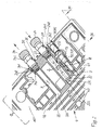
- Fig. 1 to 4 show in partial views essential, an embodiment of the invention performing parts and assemblies of an electronically controlled water flow heater 1.
- the assembly of components is sometimes different and incomplete.
- the instantaneous water heater 1 comprises a basic body 10, which is preferably produced as a plastic injection-molded part and which is arranged and held on a base 140 of a housing 14.
- the main body 10 is preferably a single monolithic body. In particular, this forms a channel system comprising end channels 2, 3 and a channel arrangement 4.
- the channel arrangement 4 with channels 41, 42 and 43 is spatially separated from a region of the end channels 2, 3 and separated.
- the channel arrangement 4 is formed with the channels 41, 42, 43 and 44 in a main body part 11, which is formed by a first half of the main body 10.
- the channels 41, 42, 43 and 44 extend in a dense spatial packing parallel and over the length of the body 10.
- a second longitudinal half of the main body 10 forms a second basic body part 12.
- the body parts 11, 12 approximately matching space and area. Only at the front or inside of the main body 10, the body portions 11 and 12 overlap along the channel 44.
- the channels 41, 42, 43 and 44 are separated only by longitudinally extending narrow channel walls. This is especially the case Fig. 2 and 3 out.
- the end channels 2, 3 are formed in the base body part 12.
- the two end channels 2, 3 lie in a central plane 15 of the base body 10.
- the sectional plane II-II coincides with the center plane 15.
- the end channels 2, 3 run parallel and are formed in the region of the longitudinal center of the main body part 12. They are directed perpendicular to the channels 41, 42, 43 and 44 of the channel assembly 4.
- the channel 2 passes through an opening 221 in one piece into the channel 41 forming an inlet channel.
- the end channel 3 connects at its inner channel end 32 through an opening 321 to the channel 42, which forms an outlet channel.
- the first end channel 2 is a water inlet channel
- the second end channel 3 is a water outlet channel.
- the direction of flow of water in the end channels 2, 3 and in the channel assembly 4 is shown in the drawing with directional arrows.
- Each end channel 2, 3 is equipped with an associated line connector 24 and 34, respectively.
- the line connection pieces 24, 34 are identical.
- the line connecting piece 24 or 34 is a connection piece with a sealing foot 242 or 342 and a head part 243 or 343.
- the sealing foot 242, 342 is in a corresponding to the circular cross-section of the nozzle widened connection portion at the outer channel end 21, 31 used. It is produced with O-rings liquid and pressure-tight, detachable connection.
- the line fitting 24, 34 may be used, for example, in sealing fit and / or in screw connection. It protrudes on the housing 14 to the outside for connection to an external cold water line or to a hot water to be fed line.
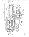
- Out Fig. 2 go out the inventive design and arrangement of a flow meter 71 a flow meter 7.
- the flow measuring device 7 is provided on the end channel 2.
- Essential components of the measuring device 7 are a flow meter insertion space 23 in the end channel 2 and a flow meter insertion part 711 inserted therein.
- the insertion space 23 has a channel cross section which is at least substantially equal to the cross section of the connection section of the end channel 2.
- the insertion space 23 forming channel space is bounded by an edge 222 of the mouth 221 and by a foot-side end of the sealing foot 242 of the conduit fitting 24.
- FIG. 2 illustrated flowmeter insert part 711 is formed according to the length and the cross section of the insertion space 23 and inserted in a form-fitting manner in this. It is trapped between the sealing foot 242 and the edge 222 of the channel mouth 221. It can be seen that the flowmeter insert part 711 is designed to be simple, in particular without a special sealing surface, seal or its own closure means. The assembly takes place simply in that the flowmeter insert part 711 is pushed into the end channel 2 by the outer channel opening 211 which is located on the main body 10 and is open, that is, when the line connection piece 24 is not yet assembled or disassembled, and is brought into the seat in the insertion space 23. Installation and vice versa Disassembly is particularly simple, since the sealing connection for opening or closing of the flowmeter insertion part 711 receiving insertion space 21 is made exclusively by the sealing surfaces or the sealing connection 240 of the line connection piece 24.
- the end channel 2 and thus also the end channel 3 have a length which provides a generous dimensioning of the length of the insertion space 23 between the line connection piece 24 and the channel mouth 221.
- the channel arrangement 4 is formed at least substantially in one half of the base body 10, namely in the base body part 11, while the extension space of the end channels 2, 3 over the length thereof at the back of the flow heater. 1 appropriate Main body outer or back side remains free of transverse channels of the channel arrangement 4 ( Fig. 2 ). At the front of the main body crosses only the channel 44 in the boundary region between the base body parts 11, 12.
- the end channel 2 is formed on a platform forming a plate member 121 of the base body part 12 and the extension of this platform along the end channel 2 about the half width of the main body 10 corresponds.
- the end channel 3 is integrally formed with a platform forming plate member 122 which extends approximately over half the width of the base body 10.
- the platforms, such as the plate member 122 may be stepped at least on one surface side. They are preferably formed as relatively thin, plate-like walls. As a result, in the area of the main body part 12, both on the one (rear) surface side and on the other (front side) surface side, particular construction and mounting space are obtained.
- a receptacle 13 is provided in the form of a pocket, which is formed perpendicular to the plate member 121, this passes through and receives the signal generator 72.
- a flat cross-section of the pocket extends with the end channel 2 in a spatial arrangement on the wall of the end channel 2.
- the signal generator 72 is shown only dash-dotted lines schematically ( Fig. 2 ).
- the arrangement and design of the flowmeter insertion space 23 described with reference to the embodiment is not limited to the design and combination with the described basic body parts 11, 12 and / or with at least one said plate element 121, 122. Furthermore, embodiments also consist in forming the flow meter insertion space 23 only or in the end channel 3 forming the water drain.
- the signal generator 72 is part of a known measuring arrangement of the flow measuring device 7.
- a measuring arrangement comprises a magnetic rotary member 731 in the form of a turbine, a propeller, an impeller or the like, which is arranged in a flow tube.
- the flowmeter insert part 711 is formed as a tube in which the rotary member 731 is arranged, and the signal generator 72 is, for example, a Hall sensor which is contactless and non-contact-responsive to flow measurement by the rotary magnetic rotary member 731 through the wall of the end channel 2 and a signal to an electronic control device 6 for controlling the temperature of a heater 5 outputs.
- the amount of water supplied to the heating device 5 is detected and the temperature of the heating device 5 is regulated.
- the heating device 5 is a bare-wire heating cartridge, as in Fig. 1 and 4 you can see. Such a heating cartridge is associated with the channel assembly 4 and it is inserted into the duct system in the region of its mid-way.
- the described or inventive arrangement and design of the flow meter 71 with the flow meter insertion space 23 are not limited to the combination with a bare wire heater 5.
- the electrical control device 6 is in the drawing of Fig. 1 to 4 not to be seen in detail. It is located in the area provided with the reference numeral 6 on a circuit board. 8
- the printed circuit board 8 extends as it does Fig. 1 and 4 it can be seen on the front side of the main body 10 in the region of the main body part 12 into it.
- the printed circuit board 8 has a contact portion 83 with contacts in Fig. 2 a printed circuit board 723 are assigned to which the Hall sensor or other signal transmitter 72 is arranged and which is provided with the PCB contacts associated mating contacts.
- the signal transmitter printed circuit board 723 belongs to said pocket receptacle 13.
- the pocket receptacle 13 receives the signal transmitter printed circuit board 723 in releasable plug-in connection.
- the transducer PCB 723 may latch into the pocket receptacle 13.
- the signal transmitter 72 is then in indirect spatial proximity to the magnetic encoder, namely the rotary member 731 of the flow meter 71.
- the mating contacts reach positionally accurate in contact with the contacts of the contact portion 83 of the printed circuit board eighth
- the described Contact connection is not limited to the flow measuring device 7 with the rotary member 731 and the Hall sensor.
Landscapes
- Engineering & Computer Science (AREA)
- Physics & Mathematics (AREA)
- Combustion & Propulsion (AREA)
- Thermal Sciences (AREA)
- Chemical & Material Sciences (AREA)
- Mechanical Engineering (AREA)
- General Engineering & Computer Science (AREA)
- Fluid Mechanics (AREA)
- General Physics & Mathematics (AREA)
- Computer Networks & Wireless Communication (AREA)
- Computer Hardware Design (AREA)
- Electromagnetism (AREA)
- Measuring Volume Flow (AREA)
Priority Applications (2)
| Application Number | Priority Date | Filing Date | Title |
|---|---|---|---|
| EP11155252.7A EP2489951B1 (fr) | 2011-02-21 | 2011-02-21 | Chauffe-eau instantané électrique |
| CN201210100342.1A CN102645025B (zh) | 2011-02-21 | 2012-02-21 | 电的连续式加热装置 |
Applications Claiming Priority (1)
| Application Number | Priority Date | Filing Date | Title |
|---|---|---|---|
| EP11155252.7A EP2489951B1 (fr) | 2011-02-21 | 2011-02-21 | Chauffe-eau instantané électrique |
Publications (2)
| Publication Number | Publication Date |
|---|---|
| EP2489951A1 true EP2489951A1 (fr) | 2012-08-22 |
| EP2489951B1 EP2489951B1 (fr) | 2017-04-05 |
Family
ID=44227784
Family Applications (1)
| Application Number | Title | Priority Date | Filing Date |
|---|---|---|---|
| EP11155252.7A Active EP2489951B1 (fr) | 2011-02-21 | 2011-02-21 | Chauffe-eau instantané électrique |
Country Status (2)
| Country | Link |
|---|---|
| EP (1) | EP2489951B1 (fr) |
| CN (1) | CN102645025B (fr) |
Cited By (1)
| Publication number | Priority date | Publication date | Assignee | Title |
|---|---|---|---|---|
| DE102018001314A1 (de) * | 2018-02-20 | 2019-08-22 | Stiebel Eltron Gmbh & Co. Kg | Warmwassererzeuger |
Families Citing this family (4)
| Publication number | Priority date | Publication date | Assignee | Title |
|---|---|---|---|---|
| CN104110822B (zh) * | 2014-07-15 | 2017-05-17 | 厦门佳普乐电子科技有限公司 | 智能加热器 |
| EP3702693B1 (fr) * | 2019-02-28 | 2021-10-27 | Gerdes Holding GmbH & Co. KG | Chauffe-eau instantané avec un régulateur de température de sécurité côté contact avec le fluide |
| EP3702690B1 (fr) * | 2019-02-28 | 2023-04-05 | Gerdes Holding GmbH & Co. KG | Chauffe-eau instantané avec un boîtier |
| PL3702691T3 (pl) * | 2019-02-28 | 2024-04-15 | Gerdes Holding Gmbh & Co. Kg | Podgrzewacz przepływowy do podgrzewania cieczy |
Citations (8)
| Publication number | Priority date | Publication date | Assignee | Title |
|---|---|---|---|---|
| DE20005327U1 (de) * | 1999-03-23 | 2000-05-31 | Vaillant Joh Gmbh & Co | Flügelrad-Durchflußmesser |
| DE10111993A1 (de) * | 2000-03-13 | 2001-09-20 | Saginomiya Seisakusho Tokyo Kk | Durchflussmengen-Sensor |
| US6487919B1 (en) * | 2001-11-06 | 2002-12-03 | Breed Automotive Technology, Inc. | Turbine flow monitoring device |
| DE202004012263U1 (de) | 2004-08-05 | 2004-10-07 | Stiebel Eltron Gmbh & Co. Kg | Durchlauferhitzer |
| EP1528371A1 (fr) * | 2003-11-03 | 2005-05-04 | Grundfos A/S | Ensemble pour installation de chauffage compact |
| EP1693651A2 (fr) * | 2005-02-21 | 2006-08-23 | Gealan Formteile GmbH | Débitmètre à turbine |
| US20080107410A1 (en) * | 2006-11-02 | 2008-05-08 | White Robert E | Tankless water heater |
| DE102007060190A1 (de) | 2007-12-14 | 2009-06-18 | BSH Bosch und Siemens Hausgeräte GmbH | Heizblock für Warmwassergerät |
Family Cites Families (1)
| Publication number | Priority date | Publication date | Assignee | Title |
|---|---|---|---|---|
| JP3581956B2 (ja) * | 2000-07-28 | 2004-10-27 | 政一 松尾 | 瞬間湯沸し器 |
-
2011
- 2011-02-21 EP EP11155252.7A patent/EP2489951B1/fr active Active
-
2012
- 2012-02-21 CN CN201210100342.1A patent/CN102645025B/zh active Active
Patent Citations (8)
| Publication number | Priority date | Publication date | Assignee | Title |
|---|---|---|---|---|
| DE20005327U1 (de) * | 1999-03-23 | 2000-05-31 | Vaillant Joh Gmbh & Co | Flügelrad-Durchflußmesser |
| DE10111993A1 (de) * | 2000-03-13 | 2001-09-20 | Saginomiya Seisakusho Tokyo Kk | Durchflussmengen-Sensor |
| US6487919B1 (en) * | 2001-11-06 | 2002-12-03 | Breed Automotive Technology, Inc. | Turbine flow monitoring device |
| EP1528371A1 (fr) * | 2003-11-03 | 2005-05-04 | Grundfos A/S | Ensemble pour installation de chauffage compact |
| DE202004012263U1 (de) | 2004-08-05 | 2004-10-07 | Stiebel Eltron Gmbh & Co. Kg | Durchlauferhitzer |
| EP1693651A2 (fr) * | 2005-02-21 | 2006-08-23 | Gealan Formteile GmbH | Débitmètre à turbine |
| US20080107410A1 (en) * | 2006-11-02 | 2008-05-08 | White Robert E | Tankless water heater |
| DE102007060190A1 (de) | 2007-12-14 | 2009-06-18 | BSH Bosch und Siemens Hausgeräte GmbH | Heizblock für Warmwassergerät |
Cited By (1)
| Publication number | Priority date | Publication date | Assignee | Title |
|---|---|---|---|---|
| DE102018001314A1 (de) * | 2018-02-20 | 2019-08-22 | Stiebel Eltron Gmbh & Co. Kg | Warmwassererzeuger |
Also Published As
| Publication number | Publication date |
|---|---|
| CN102645025A (zh) | 2012-08-22 |
| EP2489951B1 (fr) | 2017-04-05 |
| CN102645025B (zh) | 2016-12-21 |
Similar Documents
| Publication | Publication Date | Title |
|---|---|---|
| EP2489951B1 (fr) | Chauffe-eau instantané électrique | |
| EP2700912B1 (fr) | Appareil de mesure de débit à induction magnétique et son procédé de fabrication | |
| EP2107248A2 (fr) | Procédé d'intégration d'un balayeur de pression dans le boîtier d'un ventilateur | |
| EP0559938B1 (fr) | Débitmètre à ultrasons pour des liquides | |
| WO2012104052A2 (fr) | Chauffe-eau instantané servant à chauffer de l'eau | |
| EP1884723B1 (fr) | Module | |
| DE60037084T2 (de) | Hydraulische Vorrichtung mit einem Sensor für Haushaltsgeräte, insbesondere für Waschmaschinen, und Herstellungsverfahren einer solchen Vorrichtung | |
| EP1967827B1 (fr) | Débitmètre à tourbillon pour la saisie de la vitesse d'écoulement dans une canalisation | |
| DE102014114062B4 (de) | Wasserverteileinrichtung für eine Spülmaschine oder eine Waschmaschine | |
| DE102005052919B4 (de) | Mischbatterie | |
| EP3012553B1 (fr) | Composant pour une installation de chauffage | |
| EP2093515B1 (fr) | Composant partiel pour une installation de chauffage compacte | |
| EP3173538A1 (fr) | Dispositif de raccordement | |
| EP0299471B1 (fr) | Circulation de liquide, respectivement de gaz, notamment pour un système d'eau sanitaire ou de chauffage | |
| DE102010055804A1 (de) | Modulares Unterputz-System mit einem zentralen Unterputz-Mischmodul | |
| DE102009031044A1 (de) | Anschluss einer sekundären Leitung einer Reinwasser-Hauptversorgungsleitung an ein Dialysegerät oder dergleichen | |
| DE102014109806B4 (de) | Wasserauslaufarmatur für einen Waschtisch oder eine Spüle | |
| DE19651086A1 (de) | Heizblock für einen Durchlauferhitzer | |
| DE2316425C2 (fr) | ||
| EP1985976B1 (fr) | Dispositif de mesure avec des raccords | |
| DE2454065C3 (de) | Anschlußeinrichtung eines elektrischen Heißwasserbereiters | |
| AT12849U1 (de) | Vorrichtung für einen wasserzähler | |
| EP2755001B1 (fr) | Insert permettant de relier un système de compteur d'eau à une conduite | |
| EP0255936A1 (fr) | Dispositif d'interconnexion à incorporer dans un tuyau d'eau | |
| DE102008055754A1 (de) | Fluidsystem |
Legal Events
| Date | Code | Title | Description |
|---|---|---|---|
| PUAI | Public reference made under article 153(3) epc to a published international application that has entered the european phase |
Free format text: ORIGINAL CODE: 0009012 |
|
| AK | Designated contracting states |
Kind code of ref document: A1 Designated state(s): AL AT BE BG CH CY CZ DE DK EE ES FI FR GB GR HR HU IE IS IT LI LT LU LV MC MK MT NL NO PL PT RO RS SE SI SK SM TR |
|
| AX | Request for extension of the european patent |
Extension state: BA ME |
|
| 17P | Request for examination filed |
Effective date: 20130220 |
|
| REG | Reference to a national code |
Ref country code: HK Ref legal event code: DE Ref document number: 1176111 Country of ref document: HK |
|
| GRAP | Despatch of communication of intention to grant a patent |
Free format text: ORIGINAL CODE: EPIDOSNIGR1 |
|
| INTG | Intention to grant announced |
Effective date: 20160920 |
|
| GRAJ | Information related to disapproval of communication of intention to grant by the applicant or resumption of examination proceedings by the epo deleted |
Free format text: ORIGINAL CODE: EPIDOSDIGR1 |
|
| GRAR | Information related to intention to grant a patent recorded |
Free format text: ORIGINAL CODE: EPIDOSNIGR71 |
|
| GRAS | Grant fee paid |
Free format text: ORIGINAL CODE: EPIDOSNIGR3 |
|
| GRAA | (expected) grant |
Free format text: ORIGINAL CODE: 0009210 |
|
| INTC | Intention to grant announced (deleted) | ||
| INTG | Intention to grant announced |
Effective date: 20170215 |
|
| AK | Designated contracting states |
Kind code of ref document: B1 Designated state(s): AL AT BE BG CH CY CZ DE DK EE ES FI FR GB GR HR HU IE IS IT LI LT LU LV MC MK MT NL NO PL PT RO RS SE SI SK SM TR |
|
| REG | Reference to a national code |
Ref country code: GB Ref legal event code: FG4D Free format text: NOT ENGLISH |
|
| REG | Reference to a national code |
Ref country code: CH Ref legal event code: EP |
|
| REG | Reference to a national code |
Ref country code: AT Ref legal event code: REF Ref document number: 882199 Country of ref document: AT Kind code of ref document: T Effective date: 20170415 |
|
| REG | Reference to a national code |
Ref country code: IE Ref legal event code: FG4D Free format text: LANGUAGE OF EP DOCUMENT: GERMAN |
|
| REG | Reference to a national code |
Ref country code: DE Ref legal event code: R096 Ref document number: 502011011966 Country of ref document: DE |
|
| REG | Reference to a national code |
Ref country code: NL Ref legal event code: MP Effective date: 20170405 |
|
| REG | Reference to a national code |
Ref country code: LT Ref legal event code: MG4D |
|
| PG25 | Lapsed in a contracting state [announced via postgrant information from national office to epo] |
Ref country code: NL Free format text: LAPSE BECAUSE OF FAILURE TO SUBMIT A TRANSLATION OF THE DESCRIPTION OR TO PAY THE FEE WITHIN THE PRESCRIBED TIME-LIMIT Effective date: 20170405 |
|
| PG25 | Lapsed in a contracting state [announced via postgrant information from national office to epo] |
Ref country code: FI Free format text: LAPSE BECAUSE OF FAILURE TO SUBMIT A TRANSLATION OF THE DESCRIPTION OR TO PAY THE FEE WITHIN THE PRESCRIBED TIME-LIMIT Effective date: 20170405 Ref country code: HR Free format text: LAPSE BECAUSE OF FAILURE TO SUBMIT A TRANSLATION OF THE DESCRIPTION OR TO PAY THE FEE WITHIN THE PRESCRIBED TIME-LIMIT Effective date: 20170405 Ref country code: NO Free format text: LAPSE BECAUSE OF FAILURE TO SUBMIT A TRANSLATION OF THE DESCRIPTION OR TO PAY THE FEE WITHIN THE PRESCRIBED TIME-LIMIT Effective date: 20170705 Ref country code: LT Free format text: LAPSE BECAUSE OF FAILURE TO SUBMIT A TRANSLATION OF THE DESCRIPTION OR TO PAY THE FEE WITHIN THE PRESCRIBED TIME-LIMIT Effective date: 20170405 Ref country code: ES Free format text: LAPSE BECAUSE OF FAILURE TO SUBMIT A TRANSLATION OF THE DESCRIPTION OR TO PAY THE FEE WITHIN THE PRESCRIBED TIME-LIMIT Effective date: 20170405 Ref country code: GR Free format text: LAPSE BECAUSE OF FAILURE TO SUBMIT A TRANSLATION OF THE DESCRIPTION OR TO PAY THE FEE WITHIN THE PRESCRIBED TIME-LIMIT Effective date: 20170706 |
|
| PG25 | Lapsed in a contracting state [announced via postgrant information from national office to epo] |
Ref country code: BG Free format text: LAPSE BECAUSE OF FAILURE TO SUBMIT A TRANSLATION OF THE DESCRIPTION OR TO PAY THE FEE WITHIN THE PRESCRIBED TIME-LIMIT Effective date: 20170705 Ref country code: SE Free format text: LAPSE BECAUSE OF FAILURE TO SUBMIT A TRANSLATION OF THE DESCRIPTION OR TO PAY THE FEE WITHIN THE PRESCRIBED TIME-LIMIT Effective date: 20170405 Ref country code: PL Free format text: LAPSE BECAUSE OF FAILURE TO SUBMIT A TRANSLATION OF THE DESCRIPTION OR TO PAY THE FEE WITHIN THE PRESCRIBED TIME-LIMIT Effective date: 20170405 Ref country code: IS Free format text: LAPSE BECAUSE OF FAILURE TO SUBMIT A TRANSLATION OF THE DESCRIPTION OR TO PAY THE FEE WITHIN THE PRESCRIBED TIME-LIMIT Effective date: 20170805 Ref country code: RS Free format text: LAPSE BECAUSE OF FAILURE TO SUBMIT A TRANSLATION OF THE DESCRIPTION OR TO PAY THE FEE WITHIN THE PRESCRIBED TIME-LIMIT Effective date: 20170405 Ref country code: LV Free format text: LAPSE BECAUSE OF FAILURE TO SUBMIT A TRANSLATION OF THE DESCRIPTION OR TO PAY THE FEE WITHIN THE PRESCRIBED TIME-LIMIT Effective date: 20170405 |
|
| REG | Reference to a national code |
Ref country code: DE Ref legal event code: R097 Ref document number: 502011011966 Country of ref document: DE |
|
| PG25 | Lapsed in a contracting state [announced via postgrant information from national office to epo] |
Ref country code: CZ Free format text: LAPSE BECAUSE OF FAILURE TO SUBMIT A TRANSLATION OF THE DESCRIPTION OR TO PAY THE FEE WITHIN THE PRESCRIBED TIME-LIMIT Effective date: 20170405 Ref country code: RO Free format text: LAPSE BECAUSE OF FAILURE TO SUBMIT A TRANSLATION OF THE DESCRIPTION OR TO PAY THE FEE WITHIN THE PRESCRIBED TIME-LIMIT Effective date: 20170405 Ref country code: DK Free format text: LAPSE BECAUSE OF FAILURE TO SUBMIT A TRANSLATION OF THE DESCRIPTION OR TO PAY THE FEE WITHIN THE PRESCRIBED TIME-LIMIT Effective date: 20170405 Ref country code: EE Free format text: LAPSE BECAUSE OF FAILURE TO SUBMIT A TRANSLATION OF THE DESCRIPTION OR TO PAY THE FEE WITHIN THE PRESCRIBED TIME-LIMIT Effective date: 20170405 Ref country code: SK Free format text: LAPSE BECAUSE OF FAILURE TO SUBMIT A TRANSLATION OF THE DESCRIPTION OR TO PAY THE FEE WITHIN THE PRESCRIBED TIME-LIMIT Effective date: 20170405 |
|
| PLBE | No opposition filed within time limit |
Free format text: ORIGINAL CODE: 0009261 |
|
| STAA | Information on the status of an ep patent application or granted ep patent |
Free format text: STATUS: NO OPPOSITION FILED WITHIN TIME LIMIT |
|
| PG25 | Lapsed in a contracting state [announced via postgrant information from national office to epo] |
Ref country code: IT Free format text: LAPSE BECAUSE OF FAILURE TO SUBMIT A TRANSLATION OF THE DESCRIPTION OR TO PAY THE FEE WITHIN THE PRESCRIBED TIME-LIMIT Effective date: 20170405 Ref country code: SM Free format text: LAPSE BECAUSE OF FAILURE TO SUBMIT A TRANSLATION OF THE DESCRIPTION OR TO PAY THE FEE WITHIN THE PRESCRIBED TIME-LIMIT Effective date: 20170405 |
|
| 26N | No opposition filed |
Effective date: 20180108 |
|
| REG | Reference to a national code |
Ref country code: HK Ref legal event code: GR Ref document number: 1176111 Country of ref document: HK |
|
| PG25 | Lapsed in a contracting state [announced via postgrant information from national office to epo] |
Ref country code: SI Free format text: LAPSE BECAUSE OF FAILURE TO SUBMIT A TRANSLATION OF THE DESCRIPTION OR TO PAY THE FEE WITHIN THE PRESCRIBED TIME-LIMIT Effective date: 20170405 |
|
| REG | Reference to a national code |
Ref country code: CH Ref legal event code: PL |
|
| PG25 | Lapsed in a contracting state [announced via postgrant information from national office to epo] |
Ref country code: MC Free format text: LAPSE BECAUSE OF FAILURE TO SUBMIT A TRANSLATION OF THE DESCRIPTION OR TO PAY THE FEE WITHIN THE PRESCRIBED TIME-LIMIT Effective date: 20170405 Ref country code: MT Free format text: LAPSE BECAUSE OF FAILURE TO SUBMIT A TRANSLATION OF THE DESCRIPTION OR TO PAY THE FEE WITHIN THE PRESCRIBED TIME-LIMIT Effective date: 20170405 |
|
| REG | Reference to a national code |
Ref country code: IE Ref legal event code: MM4A |
|
| REG | Reference to a national code |
Ref country code: BE Ref legal event code: MM Effective date: 20180228 |
|
| PG25 | Lapsed in a contracting state [announced via postgrant information from national office to epo] |
Ref country code: LU Free format text: LAPSE BECAUSE OF NON-PAYMENT OF DUE FEES Effective date: 20180221 Ref country code: CH Free format text: LAPSE BECAUSE OF NON-PAYMENT OF DUE FEES Effective date: 20180228 Ref country code: LI Free format text: LAPSE BECAUSE OF NON-PAYMENT OF DUE FEES Effective date: 20180228 |
|
| REG | Reference to a national code |
Ref country code: FR Ref legal event code: ST Effective date: 20181031 |
|
| PG25 | Lapsed in a contracting state [announced via postgrant information from national office to epo] |
Ref country code: IE Free format text: LAPSE BECAUSE OF NON-PAYMENT OF DUE FEES Effective date: 20180221 |
|
| PG25 | Lapsed in a contracting state [announced via postgrant information from national office to epo] |
Ref country code: FR Free format text: LAPSE BECAUSE OF NON-PAYMENT OF DUE FEES Effective date: 20180228 Ref country code: BE Free format text: LAPSE BECAUSE OF NON-PAYMENT OF DUE FEES Effective date: 20180228 |
|
| REG | Reference to a national code |
Ref country code: AT Ref legal event code: MM01 Ref document number: 882199 Country of ref document: AT Kind code of ref document: T Effective date: 20180221 |
|
| REG | Reference to a national code |
Ref country code: DE Ref legal event code: R082 Ref document number: 502011011966 Country of ref document: DE Representative=s name: STORK BAMBERGER PATENTANWAELTE PARTMBB, DE Ref country code: DE Ref legal event code: R081 Ref document number: 502011011966 Country of ref document: DE Owner name: GERDES HOLDING GMBH & CO. KG, DE Free format text: FORMER OWNER: GERDES OHG, 21337 LUENEBURG, DE |
|
| PG25 | Lapsed in a contracting state [announced via postgrant information from national office to epo] |
Ref country code: AT Free format text: LAPSE BECAUSE OF NON-PAYMENT OF DUE FEES Effective date: 20180221 |
|
| PG25 | Lapsed in a contracting state [announced via postgrant information from national office to epo] |
Ref country code: TR Free format text: LAPSE BECAUSE OF FAILURE TO SUBMIT A TRANSLATION OF THE DESCRIPTION OR TO PAY THE FEE WITHIN THE PRESCRIBED TIME-LIMIT Effective date: 20170405 |
|
| PG25 | Lapsed in a contracting state [announced via postgrant information from national office to epo] |
Ref country code: PT Free format text: LAPSE BECAUSE OF FAILURE TO SUBMIT A TRANSLATION OF THE DESCRIPTION OR TO PAY THE FEE WITHIN THE PRESCRIBED TIME-LIMIT Effective date: 20170405 Ref country code: HU Free format text: LAPSE BECAUSE OF FAILURE TO SUBMIT A TRANSLATION OF THE DESCRIPTION OR TO PAY THE FEE WITHIN THE PRESCRIBED TIME-LIMIT; INVALID AB INITIO Effective date: 20110221 |
|
| PG25 | Lapsed in a contracting state [announced via postgrant information from national office to epo] |
Ref country code: CY Free format text: LAPSE BECAUSE OF FAILURE TO SUBMIT A TRANSLATION OF THE DESCRIPTION OR TO PAY THE FEE WITHIN THE PRESCRIBED TIME-LIMIT Effective date: 20170405 Ref country code: MK Free format text: LAPSE BECAUSE OF NON-PAYMENT OF DUE FEES Effective date: 20170405 |
|
| PG25 | Lapsed in a contracting state [announced via postgrant information from national office to epo] |
Ref country code: AL Free format text: LAPSE BECAUSE OF FAILURE TO SUBMIT A TRANSLATION OF THE DESCRIPTION OR TO PAY THE FEE WITHIN THE PRESCRIBED TIME-LIMIT Effective date: 20170405 |
|
| P01 | Opt-out of the competence of the unified patent court (upc) registered |
Effective date: 20230512 |
|
| PGFP | Annual fee paid to national office [announced via postgrant information from national office to epo] |
Ref country code: DE Payment date: 20240104 Year of fee payment: 14 Ref country code: GB Payment date: 20240104 Year of fee payment: 14 |