EP2489468B1 - Eyeglass lens supplying system - Google Patents
Eyeglass lens supplying system Download PDFInfo
- Publication number
- EP2489468B1 EP2489468B1 EP12001021.0A EP12001021A EP2489468B1 EP 2489468 B1 EP2489468 B1 EP 2489468B1 EP 12001021 A EP12001021 A EP 12001021A EP 2489468 B1 EP2489468 B1 EP 2489468B1
- Authority
- EP
- European Patent Office
- Prior art keywords
- tray
- unit
- conveyer line
- lens
- control unit
- Prior art date
- Legal status (The legal status is an assumption and is not a legal conclusion. Google has not performed a legal analysis and makes no representation as to the accuracy of the status listed.)
- Active
Links
- 238000012545 processing Methods 0.000 claims description 81
- 238000000034 method Methods 0.000 claims description 9
- 238000011144 upstream manufacturing Methods 0.000 claims description 9
- 230000008569 process Effects 0.000 claims description 8
- 230000007246 mechanism Effects 0.000 description 13
- 238000010586 diagram Methods 0.000 description 11
- 230000002093 peripheral effect Effects 0.000 description 10
- 230000006870 function Effects 0.000 description 6
- 238000005304 joining Methods 0.000 description 3
- 238000003754 machining Methods 0.000 description 3
- 238000012546 transfer Methods 0.000 description 3
- 230000032258 transport Effects 0.000 description 3
- 239000011324 bead Substances 0.000 description 2
- 238000005520 cutting process Methods 0.000 description 2
- 238000009434 installation Methods 0.000 description 2
- 238000001179 sorption measurement Methods 0.000 description 2
- 238000013459 approach Methods 0.000 description 1
- 239000000969 carrier Substances 0.000 description 1
- 238000011161 development Methods 0.000 description 1
- 238000004519 manufacturing process Methods 0.000 description 1
- 238000012986 modification Methods 0.000 description 1
- 230000004048 modification Effects 0.000 description 1
- 238000004080 punching Methods 0.000 description 1
- 230000009467 reduction Effects 0.000 description 1
- 230000004044 response Effects 0.000 description 1
- 238000007493 shaping process Methods 0.000 description 1
- 230000002194 synthesizing effect Effects 0.000 description 1
- 238000012360 testing method Methods 0.000 description 1
- 238000003466 welding Methods 0.000 description 1
Images


Classifications
-
- B—PERFORMING OPERATIONS; TRANSPORTING
- B24—GRINDING; POLISHING
- B24B—MACHINES, DEVICES, OR PROCESSES FOR GRINDING OR POLISHING; DRESSING OR CONDITIONING OF ABRADING SURFACES; FEEDING OF GRINDING, POLISHING, OR LAPPING AGENTS
- B24B9/00—Machines or devices designed for grinding edges or bevels on work or for removing burrs; Accessories therefor
- B24B9/02—Machines or devices designed for grinding edges or bevels on work or for removing burrs; Accessories therefor characterised by a special design with respect to properties of materials specific to articles to be ground
- B24B9/06—Machines or devices designed for grinding edges or bevels on work or for removing burrs; Accessories therefor characterised by a special design with respect to properties of materials specific to articles to be ground of non-metallic inorganic material, e.g. stone, ceramics, porcelain
- B24B9/08—Machines or devices designed for grinding edges or bevels on work or for removing burrs; Accessories therefor characterised by a special design with respect to properties of materials specific to articles to be ground of non-metallic inorganic material, e.g. stone, ceramics, porcelain of glass
- B24B9/14—Machines or devices designed for grinding edges or bevels on work or for removing burrs; Accessories therefor characterised by a special design with respect to properties of materials specific to articles to be ground of non-metallic inorganic material, e.g. stone, ceramics, porcelain of glass of optical work, e.g. lenses, prisms
- B24B9/148—Machines or devices designed for grinding edges or bevels on work or for removing burrs; Accessories therefor characterised by a special design with respect to properties of materials specific to articles to be ground of non-metallic inorganic material, e.g. stone, ceramics, porcelain of glass of optical work, e.g. lenses, prisms electrically, e.g. numerically, controlled
-
- B—PERFORMING OPERATIONS; TRANSPORTING
- B24—GRINDING; POLISHING
- B24B—MACHINES, DEVICES, OR PROCESSES FOR GRINDING OR POLISHING; DRESSING OR CONDITIONING OF ABRADING SURFACES; FEEDING OF GRINDING, POLISHING, OR LAPPING AGENTS
- B24B13/00—Machines or devices designed for grinding or polishing optical surfaces on lenses or surfaces of similar shape on other work; Accessories therefor
- B24B13/0031—Machines having several working posts; Feeding and manipulating devices
-
- B—PERFORMING OPERATIONS; TRANSPORTING
- B24—GRINDING; POLISHING
- B24B—MACHINES, DEVICES, OR PROCESSES FOR GRINDING OR POLISHING; DRESSING OR CONDITIONING OF ABRADING SURFACES; FEEDING OF GRINDING, POLISHING, OR LAPPING AGENTS
- B24B41/00—Component parts such as frames, beds, carriages, headstocks
- B24B41/005—Feeding or manipulating devices specially adapted to grinding machines
-
- B—PERFORMING OPERATIONS; TRANSPORTING
- B24—GRINDING; POLISHING
- B24B—MACHINES, DEVICES, OR PROCESSES FOR GRINDING OR POLISHING; DRESSING OR CONDITIONING OF ABRADING SURFACES; FEEDING OF GRINDING, POLISHING, OR LAPPING AGENTS
- B24B9/00—Machines or devices designed for grinding edges or bevels on work or for removing burrs; Accessories therefor
- B24B9/02—Machines or devices designed for grinding edges or bevels on work or for removing burrs; Accessories therefor characterised by a special design with respect to properties of materials specific to articles to be ground
- B24B9/06—Machines or devices designed for grinding edges or bevels on work or for removing burrs; Accessories therefor characterised by a special design with respect to properties of materials specific to articles to be ground of non-metallic inorganic material, e.g. stone, ceramics, porcelain
- B24B9/08—Machines or devices designed for grinding edges or bevels on work or for removing burrs; Accessories therefor characterised by a special design with respect to properties of materials specific to articles to be ground of non-metallic inorganic material, e.g. stone, ceramics, porcelain of glass
- B24B9/14—Machines or devices designed for grinding edges or bevels on work or for removing burrs; Accessories therefor characterised by a special design with respect to properties of materials specific to articles to be ground of non-metallic inorganic material, e.g. stone, ceramics, porcelain of glass of optical work, e.g. lenses, prisms
- B24B9/146—Accessories, e.g. lens mounting devices
Definitions
- the present invention relates an eyeglass lens supplying system for supplying an eyeglass lens to a plurality of eyeglass lens peripheral edge processing apparatuses.
- a system in which a plurality of lens peripheral edge processing apparatuses are arranged, and the tray with the lens placed thereon is automatically transported to the lens peripheral edge processing apparatus by a conveyor line such as a belt (for example, see JP-A-2000-94283 ( US2002/034921A1 ).
- the lens in the tray transported to the processing apparatus by the conveyor line is moved to the processing apparatus by a robot.
- the lens processed by the processing apparatus is returned to the tray on the conveyor line by the robot again.
- the tray with the processed lens placed thereon is transported to a downstream side by the conveyor line.
- a plurality of processing apparatus is arranged, and a system of a conveyor line for transporting a tray receiving a lens to each processing apparatus is established.
- the system of the conveyor line of the related art using a plurality of processing apparatuss was configured, for example, as below.
- An individual conveyor line corresponding to the processing apparatus was installed in parallel (or in a branched manner) with respect to a tray carrying-in main conveyor line. Furthermore, separately from the tray carrying-in main conveyor line, a tray carrying-out main conveyor line was provided. The tray carrying-out main conveyor line was provided in parallel with respect to the tray carrying-in main conveyor line. In the case of this configuration, the tray transported in the main conveyor line is distributively transported to each individual conveyor line by a tray distributing mechanism which is prepared for the number of the individual conveyor lines. The lens placed on the tray on the individual conveyor line is moved to the processing apparatus by the robot. The lens processed in the processing apparatus is returned to the tray on the individual conveyor line by the robot again. The tray with the processed lens placed thereon joins the carrying-out main conveyor line by the individual conveyor line.
- EP 1 457 290 A1 discloses a single conveyer line unit including two machining apparatuses, a first conveyer and a third conveyer for conveying a tray, a second conveyer for conveying a tray to a front of each of the machining apparatus, and robot hands for moving the tray.
- WO 2005/095049 A1 discloses a modular transfer system for workpieces in which modules used for metal-cutting and non-cutting machining processes, such as ball-type engagement, calking, punching, shaping, riveting, cementing, welding, placing, chipping, measuring, testing etc. are arranged in one line, wherein the positioning of workpiece carriers is carried out in a production module with the same CNC axis systems and the same servodrives as the workpiece carrier transfer. A separate conveyor belt is thus not required for the transfer.
- modules used for metal-cutting and non-cutting machining processes such as ball-type engagement, calking, punching, shaping, riveting, cementing, welding, placing, chipping, measuring, testing etc.
- a technical object of the present invention is to provide an economically advantageous eyeglass lens supplying system which is able to suppress an increase in size of the system.
- an eyeglass les supplying system which suppresses an increase in size of the lens supplying system and an increase in installation space and is economically advantageous.
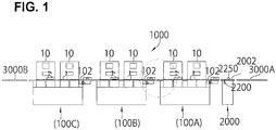
- FIG. 1 is an overall schematic diagram of an eyeglass lens supplying system according to the present invention.
- An eyeglass lens supplying system 1000 includes a plurality of individual conveyor line units 100 (hereinafter RCL units) having at least one belt type conveyor line 102 for transporting a tray TR.
- Each RCL unit 100 includes a base 101 and at least one eyeglass lens peripheral edge processing apparatus 10 is placed in on the base 101 in response to the conveyor line 102.
- the processing apparatus 10 has a lens chuck shaft which holds an eyeglass lens LE, and a peripheral edge processing tool which processes the peripheral edge of the lens LE, and controls the relative movement between the lens LE and the circumferential processing tool based on an input bead form to process the peripheral edge of the lens LE. Since the configuration of the processing apparatus 10 is disclosed as is well known in JP-2004-34167 or the like, the description thereof will be omitted.
- the system 1000 includes three RCL units 100 (hereinafter, when distinguishing three RCL units 100, reference numerals 100A, 100B, and 100C are used).
- the respective RCL units 100 are connected to each other in series. That is, by connecting conveyor lines 102 included in each RCL unit 100 to each other in series, the conveyor lines 102 are connected so as to form substantially one conveyer line when the plurality of conveyer line units 100 are arranged.
- the tray TR is transported from a conveyor line 102 included in a RCL unit 100A of an upstream side (a right side of Fig. 1 ) to a conveyor line 102 included in a RCL unit 100C of a downstream side (a left side of Fig. 1 ).
- a carrying-in conveyor line 3000A for carrying in the tray TR with a non-processed lens LE placed thereon is arranged on the upstream side of the RCL unit 100A.
- a carrying-out conveyor line 3000B for carrying out the tray TR with a processed lens LE placed thereon is arranged on the downstream side of the RCL unit 100C.
- a distributing unit 2000 having a conveyor line 2002 is arranged between the RCL unit 100A and the carrying-in conveyor line 3000A. That is, the distributing unit 2000 is provided at an upstream side of the RCL unit 100A which is located at the uppermost stream side among the RCL units 100A.
- the distributing unit 2000 functions as a tray supplying unit which supplies the tray TR to the conveyer line 102 of the RCL unit 100A which is located at the uppermost stream side, and includes a stopper unit 2200 which stops the movement of the tray TR to be transported from the carrying-in conveyor line 3000A of the upstream side, an identifier reader (a barcode reader) 2250, and a main control unit 2050.
- Fig. 2 is an exterior perspective view for describing a configuration of the individual conveyor line unit 100.
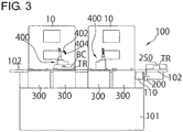
- Fig. 3 is a schematic front view of the individual conveyor line unit 100.
- the conveyor line 102 has two belts 104, and two belts 104 are concurrently transported by a driving portion 110.
- the conveyor line 102 may be configured by various methods such as a roller type in addition to being configured by the belt type like the present embodiment.
- the conveyor line 102 is arranged on the base 101.
- the tray TR mounted on the tray 104 is transported from the right side to the left side of Fig. 3 .
- a stopper unit 200 On the upstream side (the right side of Fig. 3 ) of the conveyor line 102, and an identifier reader 250 (a barcode reader) which reads a barcode BC that is an identifier attached to the tray TR, are arranged.
- Figs. 4A and 4B are configuration diagrams of the stopper unit 200 which are viewed (viewed from Fig. 3 ) from left of an advancing direction of the tray TR.
- the stop unit 200 has a left base 202L and a right base 202R which are held rotatably along a guide shaft 203 extended in a left and right direction of Fig. 4A (Fig. 4B ).
- stopper pins 204 vertically stand, respectively.
- the left base 202L and the right base 202R are moved in the left and right direction so as to approach and be separated from each other by the driving portion 206 having a motor 208.
- the driving portion 206 can be constituted by a known moving mechanism such as a rack and a pinion mechanism.
- Fig. 4A shows a state where two stopper pins 204 are opened so as to be wider than a width WY of the tray TR mounted on the belt 104. In this case, the tray TR is transported by the movement of the belt 104.
- Fig. 4B shows a state where two stopper pins 204 are closed so as to be narrower than a width WY (a width of a direction perpendicular to the advancing direction of the tray TR) of the tray TR. In this case, the stopper hinge 204 comes into contact with a leg portion of the tray TR, and the movement of the tray TR is stopped with respect to the movement of the tray 104.
- an identifier reader 250 which reads the barcode BC attached to the tray TR, is concurrently shown.
- the barcode BC is read by the identifier reader 250.
- a tray lifting unit 300 as a tray moving unit, which moves the tray TR from the upper portion of the conveyor line 104 and puts the tray TR onto the conveyor line 104 again, is arranged corresponding to the processing apparatus 10.
- the tray lifting unit 300 separates at least two trays TR from the conveyer line 104 for one processing apparatus, and moves it to predetermined standby positions provided for trays waiting for lens processing. In the present example, two tray lifting units 300 corresponding to one processing apparatus 10 are arranged.
- Fig. 3 since two processing apparatuses are arranged with respect to the RCL unit 100, four tray lifting units 300 are arranged with respect to the RCL unit 100.
- Fig. 5 is an explanatory diagram of the tray lifting unit 300.
- the tray TR mounted on the conveyor line 102 (the belt 104) is transported in an arrow AX direction.
- the tray lifting unit 300 has a plate 302 on which a leg portion of a lower end of the tray TR is mounted.
- the plate 302 is attached to the upper portion of the base portion 304 of the vertical movement.
- the base portion 304 is moved in the up and down direction by a vertical moving mechanism 310 having a motor 306.
- the vertical moving mechanism 310 is constituted by a slide mechanism which has a transport screw connected to a rotation shaft of the motor 306, or a well known slide mechanism such as a belt type slide mechanism.
- a stopper member, 320 which stop the transportation of the tray TR, are attached with the conveyor line 102 (two belts 104) interposed therebetween.
- a gap between two stopper members 320 is narrower than a width WY of the tray TR.
- a contact member 322 which regulates the position of the tray TR in the width WY direction, is placed on the plate 302. The contact member 322 comes into contact with the side surface of the tray TR.
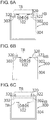
- Figs. 6A to 6C are explanatory diagrams of the vertical movement of the tray lifting unit 300.
- Fig. 6A shows a state where the base portion 304 is in a lowermost retracted position and an upper end of the stopper member 320 is in a position lower than a height HB of the belt 104 of the conveyor belt 102.
- the tray TR is not stopped when being transported by the conveyor line 102 (the belt 104), but passes through the upper portion of the tray lifting unit 300.
- the plate 302 rises to the same height as the height HB of the belt 104. At this time, the stopper member 320 comes into contact with the tray TR, and the transportation of the tray TR is stopped.
- Fig. 6C is a diagram of a state where the tray TR mounted on the plate 302 is separated from the upper portion of the belt 104 by raising the plate 302 with respect to Fig. 6B .
- the plate 302 rises to a predetermined position higher than the height of the tray TR transported by the belt 104. As a result, it is possible to cause the tray TR transported by the belt 104 to pass through.
- a robot 400 is placed as a lens moving unit for moving to tray TR again.
- the robot 400 is constituted by the same mechanism as a robot hand unit disclosed in JP-A-2004-34167 .
- the robot 400 is moved in the left and right direction of Fig. 3 along a rail extended in parallel to the belt 104.
- the robot 400 has an arm 402 moved and rotated vertically, and an adsorption portion 404 which adsorbs the lens LE is attached to a tip of the arm 402.
- the lens LE on the tray TR is held by the adsorption portion 404 and is moved to a lens chuck included in the processing apparatus 10 by the movement of the robot 400.
- At least one robot 400 may be provided in the RCL unit 100.
- two robots 400 are provided in the RCL unit 100.
- the lens LE is effectively moved between the tray TR and the processing apparatus 10 by two robots 400.
- Fig. 7 is a control block diagram of the eyeglass lens supplying system 1000.
- the RCL unit 100 includes an individual control unit 50.
- the individual control unit 50 is connected to the processing apparatus 10, the driving portion 110 of the conveyor line 102, the stopper unit 200, the identifier reader 250, the tray lifting unit 300, and the robot 400, sends the control signal to those components, and controls those components.
- the RCL unit 100 having the configuration as described above has the same configuration as that of the individual conveyor line unit indicated by reference numerals 100A, 100B, and 100C. For this reason, in the RCL units 100B and 100C, only the individual control unit 50 is shown, and other configurations are omitted.
- the individual control unit 50 included in each RCL unit 100 is connected to a main control unit 2050 included in the distributing unit 2000.
- the distributing unit 2000 includes a stopper unit 2200 having the same configuration as that of the stopper unit 200 of Figs. 4A and 4B .
- the distributing unit 2000 includes an identifier reader 2250 that reads the barcode BC attached to the tray TR.
- the driving portion 2110, the stopper unit 2200, and the identifier reader 2250 of the conveyor line 2002 are connected to the main control unit 2050.
- the processing apparatus 10 is connected to the host computer HC. In the host computer HC, a processing condition data of the lens LE corresponding to a processing number is stored. The processing numbers of the pair of left and right lenses LE are assigned to the barcode BC.
- the barcode BC assigned with the processing number is attached to the tray TR.
- the barcode BC obtained by the individual control unit 50 is transmitted to the processing apparatus 10.
- the processing apparatus 10 obtains the processing condition data such as a bead form corresponding to the barcode BC from the host computer HC.
- the peripheral edge of the lens LE is processed according to the processing condition data by the processing apparatus 10.
- the carrying-in conveyor line 3000A is mounted with the tray TR with a non-processed lens LE placed thereon.
- the tray TR is moved to the conveyor line 2002 of the distributing unit 2000.
- the main control unit 2050 operates the stopper unit 2200 to temporarily stop the movement of the tray TR, and reads the barcode of the tray TR by the identifier reader 2250.
- a number (in an example of Fig. 1 , three RCL units 100A, 100B, and 100C) of the RCL units 100 connected to the downstream side, and a number (that is, a number of the tray lifting units 300 included in the respective RCL unit 100) of the trays TR capable of being received in the respective RCL units 100 are registered. Furthermore, when the tray TR does not exist on the standby position of the tray lifting unit 300, and the tray lifting unit 300 is able to receive (carry in) a new tray TR, the control unit 50 of the RCL unit 100 transmits a request signal requesting the tray TR to the main control unit 2050.
- the main control unit 2050 determines the RCL unit 100 of a carrying-out destination of the tray TR having the barcode which is read by the identifier reader 2250, and then, transmits the signal of the read barcode to the control unit 50 of the RCL unit 100 of the determined carrying-out destination.
- the tray TR can be moved to each standby position of any tray lifting unit 300 in the entire RCL unit 100.
- the respective control unit 50 sends the request of the number of the tray lifting unit 300 included in the RCL unit 100 for which it is responsible to the main control unit 2050.
- the main control unit 2050 communicates with each control unit 50, and determines the RCL unit 100 to which the tray TR on the carrying-in conveyer line 3000A based on the request. Alternatively, the main control unit 2050 may determine the processing apparatus 10 which processes the lens in the tray of the carrying-in conveyer line 3000A.
- the main control unit 2050 sends a signal of a barcode BC which is the identification information attached to the tray TR to the control unit of each RCL unit 100.
- the main control unit 2050 determines the RCL unit 100 of the carrying-out destination so as to sequentially transport the tray TR from the lowest RCL unit 100C. That is, the main control unit 2050 distributively transports the first tray TR to the RCL unit 100C, and transmits the signal of the barcode read by the reader 2250 to the control unit 50 of the unit 100C. After that, the main control unit 2050 opens the stopper pin 204 of the stopper unit 2200, and supplies the tray TR to the RCL unit 100A of the downstream side. Next, the control unit 2050 closes the stopper pin 204 of the stopper unit 2200 in order to read the barcode BC of the second tray TR.
- each RCL unit 100 a reader 250 reads the barcode BC which is the identification information of the tray TR which is conveyed from the upstream.
- the control unit 50 moves the tray TR to the standby position by the tray lifting unit 300 if the read identification information matches with the sent identification information.
- the control unit 50 sends the tray TR to the downstream side RCL unit 100 if the read identification information does not matches with the sent identification information. Specific process will de described below.
- the control unit 50 of the RCL unit 100A stops the movement of the first tray TR by the stopper unit 200, and reads the barcode BC by the reader 250. Since there is no tray TR distributed to the RCL unit 100A, the control unit 50 of the RCL unit 100A opens the stopper unit 200 by the reading of the barcode BC, and causes the tray TR to pass through. The control unit 50 of the next RCL unit 100B also stops the movement of the first tray TR by the stopper unit 200, and reads the barcode BC by the reader 250. Like the case of the RCL unit 100A, since there is no tray TR distributed to the unit 100B, the control unit 50 of the RCL unit 100A also opens the stopper unit 200 by the reading of the barcode BC and causes the tray TR to pass through.
- the control unit 50 of the unit RCL 100C stops the movement of the first tray TR by the stopper unit 200, and reads the barcode BC by the reader 250. Moreover, when it is determined that there is a tray TR assigned to the RCL unit 100C by the reading of the barcode BC, the control unit 50 operates one of four tray lifting units 300 so as to process the lens LE of the tray TR by the processing apparatus 10. Firstly, the tray lifting unit 300 of the downstream side corresponding to the processing apparatus 10 is operated so as to process the lens LE by the processing apparatus 10 of the downstream side.
- the control unit 50 raises the plate 302 to a position of the height HB, whereby the stopper member 320 is moved to a position higher than the belt 104, and the tray TR transported by the belt 104 is stopped. After that, the plate 302 is further raised. As a result, as shown in Fig. 6C , the tray TR is mounted on the plate 302 and is moved to the standby position of a predetermined height.
- the control unit 50 of the RCL unit 100C operates the robot 400, and moves one of the left and right lenses LE placed on the plate TR to the processing apparatus 10 of the downstream side.
- the control unit 50 sends the processing command and the operation number of the barcode BC to the processing apparatus 10, and starts the processing of the lens LE.
- the processing apparatus 10 sends the operation number of the barcode BC to the host computer HC, and requests the processing condition data.
- the host computer HC transmits the processing condition data corresponding to the operation number to the processing apparatus 10.
- the peripheral edge processing of the lens LE is performed based on a predetermined processing condition corresponding to the operation number.
- the main control unit 2050 of the distributing unit 2000 distributes the second tray TR to the RCL unit 100B, and distributes the third tray TR to the RCL unit 100A, by the request from each control unit 50 of the RCL units 100B and 100A. Since the second tray TR is distributed to the RCL unit 100B, when the control unit 50 of the RCL unit 100A reads the barcode BC of the second tray TR like the previous description, the control unit 50 opens the stopper unit 200 and sends the same to the RCL unit 100B side.
- the control unit 50 of the RCL unit 100B operates the stopper unit 200 to read the barcode BC of the second tray TR
- the control unit 50 operates the tray lifting unit 300 of the downstream side.
- the control unit 50 of the RCL unit 100B stops the movement of the second tray TR transported by the belt 104, then raises the plate 302, and moves the tray TR to a predetermined position. After that, the robot 400 and the processing apparatus 10 are operated.
- the control unit 50 of the unit 100A identifies that the tray TR is distributed to the own RCL unit 100A by the operation of the stopper unit 200 and the reader 250. Moreover, like the previous description, the control unit 50 of the RCL unit 100A operates the tray lifting unit 300 of the downstream side, moves the tray TR to a predetermined position, and then, operates the robot 400 and the processing apparatus 10.
- the distributing destination of the tray TR transported to the conveyor line 2002 of the distributing unit 2000 is sequentially determined by the main control unit 2050 received the request signal from the respective control units 50.
- the respective control units 50 of the RCL units 100A, 100B, and 100C do not operate the tray lifting unit 300 but causes the tray TR to pass through to send it to the downstream conveyer line 102 or the carrying out conveyer line 3000B.
- the control unit 50 determines the tray lifting unit 300 on which the tray TR can be moved to the standby position, operates the tray lifting unit 300, and causes the tray TR to leave from the conveyor line 102.
- the pair of left and right lenses LE is placed on the tray TR.
- the unprocessed lenses LE which is put in the tray TR are moved by the robot 400 to the processing apparatus 10 so that the pair of left and right lenses LE is processed by the same processing apparatus 10.
- the processing apparatus 10 sends a completion signal to the control unit 50 if the processing of the lens LE is completed.
- the control unit 50 operates the robot 4500 and return the lens LE processed by the processing apparatus to the original tray TR. If one of the right and left of the lenses LE has not yet been processed and is put in the tray TR, the robot 400 operates, and moves the unprocessed lens LE to the processing apparatus 10. If the both right and left processed lenses LE are returned to the tray TR, the tray lifting unit 300 operates and puts the tray TR on the conveyer line 102.
- two tray lifting units 300 are prepared for one processing apparatus 10. For this reason, it is possible to move the tray TR to the standby position and transit to the processing of the lens LE in the tray TR prepared by the second tray lifting unit 300, without waiting for the exchange of the tray TR containing the processed lens LE with the next tray TR. That is, after the processing of the lens LE in the tray TR moved to the first standby position by the first tray lifting unit 300 is finished, while exchanging the tray TR in the first tray lifting unit 300, the lens in the tray TR moved to the second standby position by the second tray lifting unit is processed by the processing apparatus. During this processing, the tray TR is moved from the first standby position to the conveyer line 102.
- next tray TR (tray in which unprocessed lenses are put) conveyed by the conveyer line 102 is moved to the first standby position, and waits at the first standby position. Then, if the processing of the lens LE in the tray TR at the second standby position is completed, the lens LE in the tray TR waiting at the first standby position is processed. As a result, the operating efficiency of the processing apparatus 10 can be increased, and the lens LE is effectively processed.
- the tray 302 descends, and the tray TR is mounted on the belt 104 of the conveyor line 102. As a result, the tray TR is transported to the carrying-out conveyor line 3000B of the downstream side.
- the control unit 50 sends the request signal indicating that it is prepared for receiving the next tray TR to the standby position of the main control unit 2050.
- the main control unit 2050 sequentially determines the distributing destination of the tray TR in which the transportation is stopped by the stopper unit 2200. Then, the main control unit 2050 cancels the stop of the stopper unit 2200 and supplies the tray TR to the uppermost stream conveyer line 102.
- the transportation of the tray TR is stopped by the stopper unit 220, and the tray TR waits in the conveyor line 2002 of the distributing unit 2000 and the carrying-in conveyor line 3000A.
- the conveyor lines 102 each included in the plurality of RCL units 100 are arranged in series between the carrying-in conveyor line 3000A and the carrying-out conveyor line 3000B, a reduction in installation space of the eyeglass lens supplying system 1000 is promoted. Furthermore, the conveyer line 102 having the plurality of RCL units 100 are connected in series each other to form substantially one conveyer line, and further the operating process such as the transportation of the tray TR of the respective RCL units 100 are performed by the individual control unit 50 provided in each unit 100. Thus, there is no need for a large-scale control program for synthesizing the entire system 1000.
- the RCL unit 100A situated uppermost stream it is possible to cause the RCL unit 100A situated uppermost stream to have a function of the distributing unit 2000 and omit the distributing unit 2000. That is, the stopper unit 200 provided in the RCL unit 100A also functions as the stopper unit 2200, and the reader 250 provided in the RCL unit 100A also functions as the reader 2250. Furthermore, the control unit 50 of the RCL unit 100A takes a role of the function of the main control unit 2050. In this manner, the present invention can be variously modified, and the modifications are included in the present invention in the range of the same technical idea.
- the conveyer line 102 shown in Fig. 2 is designed so that the conveyer line 102 has two function of carrying-in the tray TR in which unprocessed lens are put and carrying-out the tray TR in which processed lens are put.
- the conveyer line for conveying the tray TR in which the processed lens is put can be provided separately from the conveyer line for conveying the tray TR in which the unprocessed lens in put.
- a first conveyer line 102 for conveying the tray in which the unprocessed lens is put and a second conveyer line 102 for conveying the tray in which the processed lens is put are arranged in parallel to each other and provided for each RCL unit 100.
- the second conveyers of each RCL unit 100 are also connected in series to form substantially one conveyer line.
- the tray moving unit (tray lifting unit 300) is controlled so that the tray TR in which the processed lens is put is placed on the second conveyer line. With this arrangement, the tray in which the unprocessed lens is put and the tray in which the processed lens is put are smoothly conveyed.
- the stopper unit 200 may not be operated when reading the identification information of the tray TR by the reader 250.
- the conveying time can be made short.
Landscapes
- Engineering & Computer Science (AREA)
- Mechanical Engineering (AREA)
- Chemical & Material Sciences (AREA)
- Ceramic Engineering (AREA)
- Inorganic Chemistry (AREA)
- Eyeglasses (AREA)
- Grinding And Polishing Of Tertiary Curved Surfaces And Surfaces With Complex Shapes (AREA)
- Discharge Of Articles From Conveyors (AREA)
- Constituent Portions Of Griding Lathes, Driving, Sensing And Control (AREA)
Applications Claiming Priority (2)
| Application Number | Priority Date | Filing Date | Title |
|---|---|---|---|
| JP2011031459 | 2011-02-16 | ||
| JP2012027507A JP5987338B2 (ja) | 2011-02-16 | 2012-02-10 | 眼鏡レンズ供給システム |
Publications (3)
| Publication Number | Publication Date |
|---|---|
| EP2489468A2 EP2489468A2 (en) | 2012-08-22 |
| EP2489468A3 EP2489468A3 (en) | 2014-08-20 |
| EP2489468B1 true EP2489468B1 (en) | 2017-04-12 |
Family
ID=45655057
Family Applications (1)
| Application Number | Title | Priority Date | Filing Date |
|---|---|---|---|
| EP12001021.0A Active EP2489468B1 (en) | 2011-02-16 | 2012-02-16 | Eyeglass lens supplying system |
Country Status (3)
| Country | Link |
|---|---|
| US (1) | US9031682B2 (ja) |
| EP (1) | EP2489468B1 (ja) |
| JP (1) | JP5987338B2 (ja) |
Cited By (1)
| Publication number | Priority date | Publication date | Assignee | Title |
|---|---|---|---|---|
| DE102019114439A1 (de) * | 2019-05-29 | 2020-12-03 | Frintrop GmbH | Modulares Automatisierungssystem und Verfahren zu dessen Betreiben |
Families Citing this family (8)
| Publication number | Priority date | Publication date | Assignee | Title |
|---|---|---|---|---|
| DE202012011690U1 (de) * | 2012-03-09 | 2013-03-13 | Schneider Gmbh & Co. Kg | Anlage zum Bearbeiten optischer Linsen |
| JP6225430B2 (ja) * | 2013-02-09 | 2017-11-08 | 株式会社ニデック | 眼鏡レンズ周縁加工システム、および眼鏡レンズ周縁加工プログラム |
| DE102015015040A1 (de) * | 2015-11-12 | 2017-05-18 | Schneider Gmbh & Co. Kg | Verfahren, Anlage und System zur Bearbeitung optischer Linsen |
| DE102016007837A1 (de) * | 2016-05-25 | 2017-11-30 | Schneider Gmbh & Co. Kg | Verfahren und System zur Bearbeitung optischer Linsen |
| EP3517284A1 (en) * | 2018-01-26 | 2019-07-31 | Essilor International | System and method for automated ophthalmic lens manufacturing |
| KR20210040265A (ko) | 2019-10-03 | 2021-04-13 | 가부시키가이샤 니데크 | 안경 렌즈 주연 가공 시스템 및 기록 매체 |
| CN112059818A (zh) * | 2020-08-19 | 2020-12-11 | 万盟特自动化(上海)有限公司 | 一种大型铸件打磨设备 |
| CN117798589A (zh) * | 2024-02-02 | 2024-04-02 | 江苏财经职业技术学院 | 一种辅助机器人焊接的翻转合拼装置 |
Citations (3)
| Publication number | Priority date | Publication date | Assignee | Title |
|---|---|---|---|---|
| AU708971B2 (en) * | 1994-06-10 | 1999-08-19 | Johnson & Johnson Vision Products, Inc. | Production line tracking and quality control system |
| JP2007301656A (ja) * | 2006-05-09 | 2007-11-22 | Denso Corp | 生産システム |
| EP1992474A2 (en) * | 2007-05-18 | 2008-11-19 | CooperVision International Holding Company, LP | Thermal curing methods and systems for forming contact lenses |
Family Cites Families (27)
| Publication number | Priority date | Publication date | Assignee | Title |
|---|---|---|---|---|
| US4662119A (en) | 1984-07-25 | 1987-05-05 | Haruchika Precision Company, Ltd. | Automatic lens grinding apparatus |
| US5649410A (en) * | 1994-06-10 | 1997-07-22 | Johnson & Johnson Vision Products, Inc. | Post-hydration method and apparatus for transporting, inspecting and packaging contact lenses |
| US5578331A (en) * | 1994-06-10 | 1996-11-26 | Vision Products, Inc. | Automated apparatus for preparing contact lenses for inspection and packaging |
| JP3630888B2 (ja) | 1996-10-31 | 2005-03-23 | 株式会社ニデック | レンズ搬送装置と眼鏡レンズを搬送するための眼鏡レンズ用固定カップ及びレンズ搬送方法 |
| JP3830617B2 (ja) * | 1997-05-13 | 2006-10-04 | Hoya株式会社 | フリーフローコンベアにおける搬送パレットの分離・セットの方法とシステム |
| DE19815728C2 (de) | 1998-04-08 | 2000-05-18 | Wernicke & Co Gmbh | Anlage zum Formbearbeiten der Ränder von Brillengläsern |
| JP3778707B2 (ja) | 1998-09-29 | 2006-05-24 | 株式会社ニデック | 眼鏡レンズ加工装置 |
| US6609041B1 (en) * | 1999-05-05 | 2003-08-19 | Johnson & Johnson Vision Care, Inc. | Method and system for SKU tracking and changeover |
| JP2007268706A (ja) | 2000-02-22 | 2007-10-18 | Hoya Corp | レンズ用レイアウト・ブロック装置 |
| JP4414403B2 (ja) | 2000-02-22 | 2010-02-10 | Hoya株式会社 | レンズ用レイアウト・ブロック装置および眼鏡レンズの製造方法 |
| JP2002036083A (ja) | 2000-07-24 | 2002-02-05 | Hoya Corp | 眼鏡レンズ用レイアウト・ブロック・加工装置 |
| US7051290B2 (en) * | 2001-02-20 | 2006-05-23 | Q2100, Inc. | Graphical interface for receiving eyeglass prescription information |
| US6790024B2 (en) * | 2001-02-20 | 2004-09-14 | Q2100, Inc. | Apparatus for preparing an eyeglass lens having multiple conveyor systems |
| US7139636B2 (en) * | 2001-02-20 | 2006-11-21 | Q2100, Inc. | System for preparing eyeglass lenses with bar code reader |
| US7074119B2 (en) | 2001-07-25 | 2006-07-11 | Seiko Epson Corporation | Polishing jig, conveyor tray, conveying method and conveying device |
| US6464484B1 (en) * | 2002-03-30 | 2002-10-15 | Q2100, Inc. | Apparatus and system for the production of plastic lenses |
| JP2004034167A (ja) | 2002-06-28 | 2004-02-05 | Nidek Co Ltd | 研削水除去装置及びレンズ加工システム |
| JP2004034166A (ja) | 2002-06-28 | 2004-02-05 | Nidek Co Ltd | レンズ加工システム |
| JP4138569B2 (ja) * | 2003-04-30 | 2008-08-27 | 株式会社ニデック | レンズ加工システム |
| EP1681136B1 (en) * | 2003-11-05 | 2014-08-06 | Hoya Corporation | Method for supplying lens of eyeglasses |
| US7090559B2 (en) * | 2003-11-19 | 2006-08-15 | Ait Industries Co. | Ophthalmic lens manufacturing system |
| JP2005202162A (ja) * | 2004-01-15 | 2005-07-28 | Nidek Co Ltd | レンズストック装置及びこれを有するレンズ加工システム |
| DE102004029665A1 (de) | 2004-03-30 | 2005-10-27 | Continental Teves Ag & Co. Ohg | Modulares Transfersystem für Werkstücke |
| JP4446934B2 (ja) * | 2005-06-30 | 2010-04-07 | 株式会社ニデック | 眼鏡レンズ加工装置 |
| US7785092B2 (en) * | 2005-08-09 | 2010-08-31 | Coopervision International Holding Company, Lp | Systems and methods for producing contact lenses from a polymerizable composition |
| US20100136227A1 (en) * | 2008-09-10 | 2010-06-03 | The Walman Optical Company | Lens handling in automated lens coating systems |
| DE102008041945B4 (de) * | 2008-09-10 | 2010-08-05 | Carl Zeiss Vision Gmbh | Transportbehältersystem für die Rezeptbrillenlinsenfertigung und Verfahren zum Transport von Brillenlinsen und/oder Brillenlinsenrohlingen |
-
2012
- 2012-02-10 JP JP2012027507A patent/JP5987338B2/ja active Active
- 2012-02-15 US US13/397,046 patent/US9031682B2/en active Active
- 2012-02-16 EP EP12001021.0A patent/EP2489468B1/en active Active
Patent Citations (3)
| Publication number | Priority date | Publication date | Assignee | Title |
|---|---|---|---|---|
| AU708971B2 (en) * | 1994-06-10 | 1999-08-19 | Johnson & Johnson Vision Products, Inc. | Production line tracking and quality control system |
| JP2007301656A (ja) * | 2006-05-09 | 2007-11-22 | Denso Corp | 生産システム |
| EP1992474A2 (en) * | 2007-05-18 | 2008-11-19 | CooperVision International Holding Company, LP | Thermal curing methods and systems for forming contact lenses |
Cited By (2)
| Publication number | Priority date | Publication date | Assignee | Title |
|---|---|---|---|---|
| DE102019114439A1 (de) * | 2019-05-29 | 2020-12-03 | Frintrop GmbH | Modulares Automatisierungssystem und Verfahren zu dessen Betreiben |
| DE102019114439B4 (de) * | 2019-05-29 | 2021-03-25 | TGA Technische Gebäudeausrüstung Meiningen GmbH | Modulares Automatisierungssystem und Verfahren zu dessen Betreiben |
Also Published As
| Publication number | Publication date |
|---|---|
| JP5987338B2 (ja) | 2016-09-07 |
| JP2012183633A (ja) | 2012-09-27 |
| EP2489468A2 (en) | 2012-08-22 |
| EP2489468A3 (en) | 2014-08-20 |
| US20120209416A1 (en) | 2012-08-16 |
| US9031682B2 (en) | 2015-05-12 |
Similar Documents
| Publication | Publication Date | Title |
|---|---|---|
| EP2489468B1 (en) | Eyeglass lens supplying system | |
| US10781050B2 (en) | System and method for processing of optical lenses | |
| CA2056897C (en) | Automatically operable manufacturing and machining plant | |
| KR100941334B1 (ko) | 터릿 툴 및 기계가공 툴 | |
| CN107824463B (zh) | 自动物流分拣系统和自动物流分拣方法 | |
| US7507193B2 (en) | Machine tool comprising at least one machining unit and method of machining workpieces using such a machine tool | |
| JPH0549422B2 (ja) | ||
| JP2001293643A (ja) | 生産システム | |
| US5401229A (en) | Automatic machining apparatus | |
| JP2012183633A5 (ja) | ||
| US5299476A (en) | Vertical lathe | |
| US11363748B2 (en) | Printed circuit board transport | |
| CN202449515U (zh) | 用于精密定位传送移载治具的o型传送带装置 | |
| TWI279379B (en) | Automated material handling system | |
| KR100865323B1 (ko) | 대형 시엔시 머신 장착용 보조 고속 이송 장치 | |
| JP5311095B2 (ja) | プレス用オートパレタイザ | |
| JPH05237734A (ja) | パレット交換方式の加工システム | |
| CA2491636A1 (en) | Transfer line | |
| CN202897527U (zh) | 自动定位高效率输送装置 | |
| JPH02236604A (ja) | 自律分散形加工セルの情報処理装置 | |
| CN220839166U (zh) | 一种cnc自动上下料设备 | |
| JP2001219322A (ja) | 組立装置 | |
| JP2003001543A (ja) | ワーク供給装置 | |
| JPH074109Y2 (ja) | 機械加工システムにおける搬送ライン | |
| JPH0248213Y2 (ja) |
Legal Events
| Date | Code | Title | Description |
|---|---|---|---|
| PUAI | Public reference made under article 153(3) epc to a published international application that has entered the european phase |
Free format text: ORIGINAL CODE: 0009012 |
|
| AK | Designated contracting states |
Kind code of ref document: A2 Designated state(s): AL AT BE BG CH CY CZ DE DK EE ES FI FR GB GR HR HU IE IS IT LI LT LU LV MC MK MT NL NO PL PT RO RS SE SI SK SM TR |
|
| AX | Request for extension of the european patent |
Extension state: BA ME |
|
| PUAL | Search report despatched |
Free format text: ORIGINAL CODE: 0009013 |
|
| AK | Designated contracting states |
Kind code of ref document: A3 Designated state(s): AL AT BE BG CH CY CZ DE DK EE ES FI FR GB GR HR HU IE IS IT LI LT LU LV MC MK MT NL NO PL PT RO RS SE SI SK SM TR |
|
| AX | Request for extension of the european patent |
Extension state: BA ME |
|
| RIC1 | Information provided on ipc code assigned before grant |
Ipc: B24B 9/14 20060101AFI20140711BHEP Ipc: B23Q 7/14 20060101ALI20140711BHEP Ipc: B24B 41/00 20060101ALI20140711BHEP Ipc: B24B 13/00 20060101ALI20140711BHEP |
|
| 17P | Request for examination filed |
Effective date: 20150213 |
|
| RBV | Designated contracting states (corrected) |
Designated state(s): AL AT BE BG CH CY CZ DE DK EE ES FI FR GB GR HR HU IE IS IT LI LT LU LV MC MK MT NL NO PL PT RO RS SE SI SK SM TR |
|
| 17Q | First examination report despatched |
Effective date: 20151009 |
|
| GRAP | Despatch of communication of intention to grant a patent |
Free format text: ORIGINAL CODE: EPIDOSNIGR1 |
|
| INTG | Intention to grant announced |
Effective date: 20160909 |
|
| RAP1 | Party data changed (applicant data changed or rights of an application transferred) |
Owner name: NIDEK CO., LTD. |
|
| GRAS | Grant fee paid |
Free format text: ORIGINAL CODE: EPIDOSNIGR3 |
|
| GRAA | (expected) grant |
Free format text: ORIGINAL CODE: 0009210 |
|
| AK | Designated contracting states |
Kind code of ref document: B1 Designated state(s): AL AT BE BG CH CY CZ DE DK EE ES FI FR GB GR HR HU IE IS IT LI LT LU LV MC MK MT NL NO PL PT RO RS SE SI SK SM TR |
|
| REG | Reference to a national code |
Ref country code: GB Ref legal event code: FG4D |
|
| REG | Reference to a national code |
Ref country code: CH Ref legal event code: EP |
|
| REG | Reference to a national code |
Ref country code: IE Ref legal event code: FG4D |
|
| REG | Reference to a national code |
Ref country code: AT Ref legal event code: REF Ref document number: 883378 Country of ref document: AT Kind code of ref document: T Effective date: 20170515 |
|
| REG | Reference to a national code |
Ref country code: DE Ref legal event code: R096 Ref document number: 602012030957 Country of ref document: DE |
|
| REG | Reference to a national code |
Ref country code: NL Ref legal event code: MP Effective date: 20170412 |
|
| REG | Reference to a national code |
Ref country code: LT Ref legal event code: MG4D |
|
| REG | Reference to a national code |
Ref country code: AT Ref legal event code: MK05 Ref document number: 883378 Country of ref document: AT Kind code of ref document: T Effective date: 20170412 |
|
| PG25 | Lapsed in a contracting state [announced via postgrant information from national office to epo] |
Ref country code: NL Free format text: LAPSE BECAUSE OF FAILURE TO SUBMIT A TRANSLATION OF THE DESCRIPTION OR TO PAY THE FEE WITHIN THE PRESCRIBED TIME-LIMIT Effective date: 20170412 |
|
| PG25 | Lapsed in a contracting state [announced via postgrant information from national office to epo] |
Ref country code: LT Free format text: LAPSE BECAUSE OF FAILURE TO SUBMIT A TRANSLATION OF THE DESCRIPTION OR TO PAY THE FEE WITHIN THE PRESCRIBED TIME-LIMIT Effective date: 20170412 Ref country code: HR Free format text: LAPSE BECAUSE OF FAILURE TO SUBMIT A TRANSLATION OF THE DESCRIPTION OR TO PAY THE FEE WITHIN THE PRESCRIBED TIME-LIMIT Effective date: 20170412 Ref country code: ES Free format text: LAPSE BECAUSE OF FAILURE TO SUBMIT A TRANSLATION OF THE DESCRIPTION OR TO PAY THE FEE WITHIN THE PRESCRIBED TIME-LIMIT Effective date: 20170412 Ref country code: NO Free format text: LAPSE BECAUSE OF FAILURE TO SUBMIT A TRANSLATION OF THE DESCRIPTION OR TO PAY THE FEE WITHIN THE PRESCRIBED TIME-LIMIT Effective date: 20170712 Ref country code: AT Free format text: LAPSE BECAUSE OF FAILURE TO SUBMIT A TRANSLATION OF THE DESCRIPTION OR TO PAY THE FEE WITHIN THE PRESCRIBED TIME-LIMIT Effective date: 20170412 Ref country code: FI Free format text: LAPSE BECAUSE OF FAILURE TO SUBMIT A TRANSLATION OF THE DESCRIPTION OR TO PAY THE FEE WITHIN THE PRESCRIBED TIME-LIMIT Effective date: 20170412 Ref country code: GR Free format text: LAPSE BECAUSE OF FAILURE TO SUBMIT A TRANSLATION OF THE DESCRIPTION OR TO PAY THE FEE WITHIN THE PRESCRIBED TIME-LIMIT Effective date: 20170713 |
|
| PG25 | Lapsed in a contracting state [announced via postgrant information from national office to epo] |
Ref country code: RS Free format text: LAPSE BECAUSE OF FAILURE TO SUBMIT A TRANSLATION OF THE DESCRIPTION OR TO PAY THE FEE WITHIN THE PRESCRIBED TIME-LIMIT Effective date: 20170412 Ref country code: IS Free format text: LAPSE BECAUSE OF FAILURE TO SUBMIT A TRANSLATION OF THE DESCRIPTION OR TO PAY THE FEE WITHIN THE PRESCRIBED TIME-LIMIT Effective date: 20170812 Ref country code: SE Free format text: LAPSE BECAUSE OF FAILURE TO SUBMIT A TRANSLATION OF THE DESCRIPTION OR TO PAY THE FEE WITHIN THE PRESCRIBED TIME-LIMIT Effective date: 20170412 Ref country code: PL Free format text: LAPSE BECAUSE OF FAILURE TO SUBMIT A TRANSLATION OF THE DESCRIPTION OR TO PAY THE FEE WITHIN THE PRESCRIBED TIME-LIMIT Effective date: 20170412 Ref country code: BG Free format text: LAPSE BECAUSE OF FAILURE TO SUBMIT A TRANSLATION OF THE DESCRIPTION OR TO PAY THE FEE WITHIN THE PRESCRIBED TIME-LIMIT Effective date: 20170712 Ref country code: LV Free format text: LAPSE BECAUSE OF FAILURE TO SUBMIT A TRANSLATION OF THE DESCRIPTION OR TO PAY THE FEE WITHIN THE PRESCRIBED TIME-LIMIT Effective date: 20170412 |
|
| REG | Reference to a national code |
Ref country code: FR Ref legal event code: PLFP Year of fee payment: 7 |
|
| REG | Reference to a national code |
Ref country code: DE Ref legal event code: R097 Ref document number: 602012030957 Country of ref document: DE |
|
| PG25 | Lapsed in a contracting state [announced via postgrant information from national office to epo] |
Ref country code: DK Free format text: LAPSE BECAUSE OF FAILURE TO SUBMIT A TRANSLATION OF THE DESCRIPTION OR TO PAY THE FEE WITHIN THE PRESCRIBED TIME-LIMIT Effective date: 20170412 Ref country code: RO Free format text: LAPSE BECAUSE OF FAILURE TO SUBMIT A TRANSLATION OF THE DESCRIPTION OR TO PAY THE FEE WITHIN THE PRESCRIBED TIME-LIMIT Effective date: 20170412 Ref country code: SK Free format text: LAPSE BECAUSE OF FAILURE TO SUBMIT A TRANSLATION OF THE DESCRIPTION OR TO PAY THE FEE WITHIN THE PRESCRIBED TIME-LIMIT Effective date: 20170412 Ref country code: EE Free format text: LAPSE BECAUSE OF FAILURE TO SUBMIT A TRANSLATION OF THE DESCRIPTION OR TO PAY THE FEE WITHIN THE PRESCRIBED TIME-LIMIT Effective date: 20170412 Ref country code: CZ Free format text: LAPSE BECAUSE OF FAILURE TO SUBMIT A TRANSLATION OF THE DESCRIPTION OR TO PAY THE FEE WITHIN THE PRESCRIBED TIME-LIMIT Effective date: 20170412 |
|
| PLBE | No opposition filed within time limit |
Free format text: ORIGINAL CODE: 0009261 |
|
| STAA | Information on the status of an ep patent application or granted ep patent |
Free format text: STATUS: NO OPPOSITION FILED WITHIN TIME LIMIT |
|
| PG25 | Lapsed in a contracting state [announced via postgrant information from national office to epo] |
Ref country code: SM Free format text: LAPSE BECAUSE OF FAILURE TO SUBMIT A TRANSLATION OF THE DESCRIPTION OR TO PAY THE FEE WITHIN THE PRESCRIBED TIME-LIMIT Effective date: 20170412 |
|
| 26N | No opposition filed |
Effective date: 20180115 |
|
| PG25 | Lapsed in a contracting state [announced via postgrant information from national office to epo] |
Ref country code: SI Free format text: LAPSE BECAUSE OF FAILURE TO SUBMIT A TRANSLATION OF THE DESCRIPTION OR TO PAY THE FEE WITHIN THE PRESCRIBED TIME-LIMIT Effective date: 20170412 |
|
| REG | Reference to a national code |
Ref country code: CH Ref legal event code: PL |
|
| PG25 | Lapsed in a contracting state [announced via postgrant information from national office to epo] |
Ref country code: MC Free format text: LAPSE BECAUSE OF FAILURE TO SUBMIT A TRANSLATION OF THE DESCRIPTION OR TO PAY THE FEE WITHIN THE PRESCRIBED TIME-LIMIT Effective date: 20170412 |
|
| REG | Reference to a national code |
Ref country code: IE Ref legal event code: MM4A |
|
| REG | Reference to a national code |
Ref country code: BE Ref legal event code: MM Effective date: 20180228 |
|
| PG25 | Lapsed in a contracting state [announced via postgrant information from national office to epo] |
Ref country code: LI Free format text: LAPSE BECAUSE OF NON-PAYMENT OF DUE FEES Effective date: 20180228 Ref country code: LU Free format text: LAPSE BECAUSE OF NON-PAYMENT OF DUE FEES Effective date: 20180216 Ref country code: CH Free format text: LAPSE BECAUSE OF NON-PAYMENT OF DUE FEES Effective date: 20180228 |
|
| PG25 | Lapsed in a contracting state [announced via postgrant information from national office to epo] |
Ref country code: IE Free format text: LAPSE BECAUSE OF NON-PAYMENT OF DUE FEES Effective date: 20180216 |
|
| PG25 | Lapsed in a contracting state [announced via postgrant information from national office to epo] |
Ref country code: BE Free format text: LAPSE BECAUSE OF NON-PAYMENT OF DUE FEES Effective date: 20180228 |
|
| PG25 | Lapsed in a contracting state [announced via postgrant information from national office to epo] |
Ref country code: MT Free format text: LAPSE BECAUSE OF NON-PAYMENT OF DUE FEES Effective date: 20180216 |
|
| PG25 | Lapsed in a contracting state [announced via postgrant information from national office to epo] |
Ref country code: TR Free format text: LAPSE BECAUSE OF FAILURE TO SUBMIT A TRANSLATION OF THE DESCRIPTION OR TO PAY THE FEE WITHIN THE PRESCRIBED TIME-LIMIT Effective date: 20170412 |
|
| PG25 | Lapsed in a contracting state [announced via postgrant information from national office to epo] |
Ref country code: PT Free format text: LAPSE BECAUSE OF FAILURE TO SUBMIT A TRANSLATION OF THE DESCRIPTION OR TO PAY THE FEE WITHIN THE PRESCRIBED TIME-LIMIT Effective date: 20170412 Ref country code: HU Free format text: LAPSE BECAUSE OF FAILURE TO SUBMIT A TRANSLATION OF THE DESCRIPTION OR TO PAY THE FEE WITHIN THE PRESCRIBED TIME-LIMIT; INVALID AB INITIO Effective date: 20120216 |
|
| PG25 | Lapsed in a contracting state [announced via postgrant information from national office to epo] |
Ref country code: MK Free format text: LAPSE BECAUSE OF NON-PAYMENT OF DUE FEES Effective date: 20170412 Ref country code: CY Free format text: LAPSE BECAUSE OF FAILURE TO SUBMIT A TRANSLATION OF THE DESCRIPTION OR TO PAY THE FEE WITHIN THE PRESCRIBED TIME-LIMIT Effective date: 20170412 |
|
| PG25 | Lapsed in a contracting state [announced via postgrant information from national office to epo] |
Ref country code: AL Free format text: LAPSE BECAUSE OF FAILURE TO SUBMIT A TRANSLATION OF THE DESCRIPTION OR TO PAY THE FEE WITHIN THE PRESCRIBED TIME-LIMIT Effective date: 20170412 |
|
| PGFP | Annual fee paid to national office [announced via postgrant information from national office to epo] |
Ref country code: FR Payment date: 20230110 Year of fee payment: 12 |
|
| PGFP | Annual fee paid to national office [announced via postgrant information from national office to epo] |
Ref country code: IT Payment date: 20230110 Year of fee payment: 12 |
|
| P01 | Opt-out of the competence of the unified patent court (upc) registered |
Effective date: 20230517 |
|
| PGFP | Annual fee paid to national office [announced via postgrant information from national office to epo] |
Ref country code: DE Payment date: 20231228 Year of fee payment: 13 Ref country code: GB Payment date: 20240108 Year of fee payment: 13 |